US8033330B2 - Tool string threads - Google Patents
Tool string threads Download PDFInfo
- Publication number
- US8033330B2 US8033330B2 US11/947,949 US94794907A US8033330B2 US 8033330 B2 US8033330 B2 US 8033330B2 US 94794907 A US94794907 A US 94794907A US 8033330 B2 US8033330 B2 US 8033330B2
- Authority
- US
- United States
- Prior art keywords
- thread
- threads
- component
- threadform
- face
- Prior art date
- Legal status (The legal status is an assumption and is not a legal conclusion. Google has not performed a legal analysis and makes no representation as to the accuracy of the status listed.)
- Expired - Fee Related, expires
Links
- 230000007423 decrease Effects 0.000 claims description 2
- 230000003467 diminishing effect Effects 0.000 claims 2
- 238000010586 diagram Methods 0.000 description 14
- 238000005553 drilling Methods 0.000 description 8
- 230000015572 biosynthetic process Effects 0.000 description 2
- 238000004891 communication Methods 0.000 description 2
- 230000001934 delay Effects 0.000 description 2
- 238000000034 method Methods 0.000 description 2
- 238000012986 modification Methods 0.000 description 2
- 230000004048 modification Effects 0.000 description 2
- 238000005096 rolling process Methods 0.000 description 2
- 208000013201 Stress fracture Diseases 0.000 description 1
- 239000012530 fluid Substances 0.000 description 1
- 238000003754 machining Methods 0.000 description 1
- 239000000696 magnetic material Substances 0.000 description 1
- 239000002184 metal Substances 0.000 description 1
- 238000012544 monitoring process Methods 0.000 description 1
- 230000002028 premature Effects 0.000 description 1
Images


Classifications
-
- E—FIXED CONSTRUCTIONS
- E21—EARTH DRILLING; MINING
- E21B—EARTH DRILLING, e.g. DEEP DRILLING; OBTAINING OIL, GAS, WATER, SOLUBLE OR MELTABLE MATERIALS OR A SLURRY OF MINERALS FROM WELLS
- E21B47/00—Survey of boreholes or wells
- E21B47/01—Devices for supporting measuring instruments on drill bits, pipes, rods or wirelines; Protecting measuring instruments in boreholes against heat, shock, pressure or the like
-
- E—FIXED CONSTRUCTIONS
- E21—EARTH DRILLING; MINING
- E21B—EARTH DRILLING, e.g. DEEP DRILLING; OBTAINING OIL, GAS, WATER, SOLUBLE OR MELTABLE MATERIALS OR A SLURRY OF MINERALS FROM WELLS
- E21B17/00—Drilling rods or pipes; Flexible drill strings; Kellies; Drill collars; Sucker rods; Cables; Casings; Tubings
- E21B17/02—Couplings; joints
- E21B17/04—Couplings; joints between rod or the like and bit or between rod and rod or the like
- E21B17/042—Threaded
Definitions
- the current application relates to downhole drilling.
- downhole drilling torque acts on downhole drilling tools which if directed towards drilling instrumentation can lead to their failure.
- These devices may be very expensive to replace and if damaged could lead to drilling delays and other possible failures.
- U.S. Pat. No. 6,447,025 to Smith which is herein incorporated by reference for all that it contains discloses an oilfield tubular member that includes a pin member and a box member, each have a tapered thread.
- the pin thread has a root, a crest, a pressure flank, and a stab flank.
- the box thread has a root, a crest, a pressure flank, and a stab flank.
- the pin crest has a stab flank pin crest radius and a pressure flank pin crust radius which is at least twice the radius.
- the improved oilfield connection minimizes damage to the connection during misalignment of the pin member and box member.
- U.S. Pat. No. 5,492,375 to Smith which is herein incorporated by reference for all that it contains discloses a tubular drill pipe having a pin connector at one end and a box connector at the other end has each connector adapted to mate with a connector similar to that at the opposite end of the pipe—but on another pipe, to form a tool joint.
- the connectors are of the type having two pair of axially abutting make-up faces; a primary annular shoulder formed at the inner end of the base of the pin connector, and an internal secondary shoulder at the inner extremity of the base of the box connector which abuts the end of an outermost nose section of the pin connector.
- U.S. Pat. No. 3,651,678 to Zook et al. which is incorporated by reference for all that it contains discloses a through feed thread rolling die for rolling external threads on a cylindrical work piece has an external thread thereon with relieved starting and finishing sections, the starting relief providing flat crests which form a predetermined angle with the roll axis and taper to a diameter at the starting end less than the mean height of the fully formed threads.
- a modified version tapers the starting section at the larger angle than the predetermined angle of the crests thereby reducing the length of the starting section.
- the invention includes the method of metal movement caused by the die in the formation of the thread.
- a downhole tool string component comprising a tubular body with a first and second end.
- the tubular body of the tool string comprises an inner surface and an outer surface.
- At least one sleeve is mounted about the outer surface of the tubular body.
- the tubular body comprises a shoulder near either the first or second end and is in mechanical communication with the at least one sleeve.
- a loading member near the other end of the tubular component is disposed about the outer surface and is adapted for loading the at least one sleeve against the shoulder.
- the loading member comprises an internal threadform adapted to threadingly engage an external threadform in the outer surface of the tubular body.
- Either the external threadform or the internal threadform comprises a plurality of threads with a distal thread comprising a first thread height and a proximal thread comprising a second thread height. Wherein the first thread height is greater than the second thread height and a plurality of the threads heights between the first and second thread heights accumulatively taper from the first height to the second height.
- the shoulder of the tubular body may be formed on the outer surface.
- the shoulder may be an attachment to the outer surface.
- the shoulder may also be threadedly attached to the outer surface of the tubular body.
- the thread heights may be formed in part from machining.
- the thread heights may be truncated.
- the threads of the internal threadform may comprise substantially equal heights.
- the threads of the external threadform may also comprise substantially equal heights.
- the external threadform may be between 5 and 9 inches long.
- the external threadform may also comprise tapered threads.
- the internal and external threadforms may be straight threads. One threadform from the internal threadform or the external threadform may be truncated while the other may be nontruncated.
- a pocket may be provided between the at least one sleeve and the outer surface of the tubular body. The downhole instrumentation may be secured within the pocket.
- the accumulative taper may be between 0.1-5 degrees from the loading member to the shoulder.
- the sleeve may be rotationally fixed to the tubular body.
- a stress relief groove may be disposed in the outer surface adjacent and proximal to the external threadform.
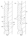
- FIG. 1 is an orthogonal diagram of an embodiment of a tool string.
- FIG. 2 is a cross-sectional diagram of an embodiment of a tool string component.
- FIG. 3 is another cross-sectional diagram of an embodiment of a tool string component.
- FIG. 4 is another cross-sectional diagram of an embodiment of a tool string component.
- FIG. 5 is another cross-sectional diagram of an embodiment of a tool string component.
- FIG. 6 is another cross-sectional diagram of an embodiment of a tool string component.
- FIG. 7 is another cross-sectional diagram of an embodiment of a tool string component.
- FIG. 8 is another cross-sectional diagram of an embodiment of a tool string component.
- FIG. 9 is another cross-sectional diagram of an embodiment of a tool string component.
- FIG. 1 is an orthogonal diagram of an embodiment of a tool string 100 comprising a drill bit 102 located at the bottom of a bore hole.
- the tool string 100 may be made of rigid drill pipe, drill collars, heavy weight pipe, jars, and/or subs.
- the tool string 100 may also comprise a sleeve 203 that may be adapted to protect downhole instrumentation. As the drill bit 102 rotates downhole the tool string 100 advances farther into the formation 105 due to the weight on the drill bit 102 and a cutting action of the drill bit 102 .
- a downhole tool string component 200 in the tool string 100 may comprise a plurality of pockets 201 , as in the embodiment of FIG. 2 .
- the pockets 201 may be formed by a plurality of flanges 202 disposed around the component 200 at different axial locations and covered by individual sleeves disposed between and around the flanges 202 .
- a first pocket 206 may be formed around an outer diameter 204 of a tubular body 205 by a first sleeve 207 disposed around the tubular body 205 such that opposite ends of the first sleeve 207 fit around at least a portion of a first flange 208 and a second flange 209 .
- a second pocket 210 may be formed around the outer diameter 204 of the tubular body 205 by a second sleeve 211 disposed around the tubular body 205 such that opposite ends of the second sleeve 211 fit around at least a portion of the second flange 209 and a third flange 212 .
- a third pocket 213 may also be formed around the outer diameter 204 of the tubular body 205 by a third sleeve 214 disposed around the tubular body 205 such that opposite ends of the third sleeve 214 fit around at least a portion of the third flange 212 and a fourth flange 215 .
- the sleeves may be interlocked or keyed together near the flanges 202 for extra torsional support.
- the individual sleeves may allow for better axial and torsional flexibility of the component 200 than if the component 200 comprised a single sleeve 203 spanning the pockets 201 .
- the sleeve may also comprise a plurality of grooves adapted to allow the sleeves to stretch and/or flex with the tubular body 205 .
- At least one sleeve may be made of a non magnetic material, which may be useful in embodiments using magnetic sensors or other electronics.
- the pockets 201 may be sealed, though a sleeve and the pocket may comprise openings adapted to allow fluid to pass through the sleeve such that one of the pockets is a wet pocket.
- Downhole instrumentation 220 may be disposed within at least one of the pockets of the tool string component 200 .
- An instrumentation housing 224 may be disposed within at least one of the pockets wherein the downhole instrumentation may be disposed, which may protect the equipment from downhole conditions.
- the instrumentation may comprise sensors for monitoring downhole conditions.
- the sensors may include pressure sensors, strain sensors, flow sensors, acoustic sensors, temperature sensors, torque sensors, position sensors, vibration sensors, geophones, hydrophones, electrical potential sensors, nuclear sensors, or any combination thereof. Information gathered from the sensors may be used either by an operator at the surface or by the closed-loop system downhole for modifications during the drilling process. If the downhole instrumentation is disposed in more than one pocket, the pockets may be in electrical communication, which may be through an electrically conductive conduit disposed within the flange separating them.
- the tubular body 205 can further include a shoulder 240 extending from one end of the tubular body that is adapted to contact an end face of one of the sleeves 203 .
- the shoulder may be formed on the outer surface of the tubular body.
- the shoulder 240 may be attached to the outer surface of the tubular body 205 with a threaded connection.
- a loading member 260 can be disposed about or coupled to the outer surface at the other end of the tubular body 205 , and can be adapted to contact an end face of one of the sleeves 203 opposite the end face which contacts the shoulder 240 , for loading the one or more sleeves 203 disposed about the outer surface of the tubular body against the shoulder 240 and locking the sleeves into place.
- the loading member 260 can include an internal threadform adapted to threadingly engage an external threadform formed into the outer surface of the tubular body.
- the loading member 360 may abut one of the sleeves 340 disposed around the tubular body 320 at a first or distal end 304 of the tool string component 300 .
- the loading member 360 is adapted to form a primary shoulder 364 of the component for connection to an adjacent tool string component.
- the loading member may also lock the sleeve 340 in place.
- the loading member is threaded in a different direction than either the sleeves or thread adapted for connection to the adjacent tool string component.
- the loading member 360 may be threadedly attached to the external threadforms 330 of a tubular body 320 .
- the internal threads 370 of the loading member 360 may comprise a plurality of threads 366 of substantially equal heights, while the external threadform 330 of the tubular body 320 may comprise a plurality of threads 326 inciuding a distal thread 332 proximate the distal end 304 of the tool string component 300 having a first thread height 334 that is greater than a second thread height 338 of one or more proximal threads 336 that are closer or proximate to the sleeve 340 .
- the height differential from the distal thread 332 and proximal threads 336 may comprise a 0.1-5 degree taper.
- the internal threadform 370 and the external threadform 330 may comprise a substantially similar spacing between each of the individual threads 326 , 366 . Additionally, the individual threads 326 of the external threadform 330 of the tubular body 320 may be truncated.
- the external threadform 330 on the tubular body 320 may comprise individual threads 326 with the first or distal thread 332 comprising a greater height than one or more second or proximal threads 336
- the internal threadform 370 of the loading member 360 may comprise a plurality of threads 366 with a substantially consistent height.
- the height differential may comprise a 0.1-5 degree taper. This may allow for more compliancy between the attachment of the loading member 360 and the tubular body 320 and may prevent breakage.
- the external threadforms 330 and internal threadform 370 may extend over half the length of the loading member 360 .
- Torsion forces may travel from the proximal end 308 through the distal end 304 of the tool string component 300 along the taper of the tubular body 320 .
- the external threadform 330 may further comprise a relief groove 328 that may decrease the occurrence of stress risers in the tool string.
- the loading member 360 may be locked into place by a tool joint 380 of an adjacent tool string component.
- FIG. 5 is cross-sectional diagram of another representative embodiment 400 of the tool string component.
- the internal threadforms 470 and the external threadforms 430 may extend two-thirds the length of the loading member 460 .
- Both the internal threadform 470 of the loading member 460 and the external threadform 430 of the tubular body 420 may be tapered outwardly from the distal end 404 to the proximal end 408 of the tool string component 400 , while the thread heights of the individual threads 426 of the external threadform 430 may comprise a 0.1-5 degree taper and may be truncated.
- both the internal threadform 570 and the external threadform 530 may be linear, while the thread heights of the individual threads 566 of the internal threadform 570 may comprise a 0.1-5 degree taper and may be truncated, such as shown in FIG. 6 .
- the internal threadform 630 and external threadform 670 may be less than half the length of the loading member 660 .
- the external threadform 630 may also comprise a truncated geometry, and the internal threadform 670 may comprise a non-truncated geometry.
- the individual threads 626 , 666 of the threadforms 630 , 670 may be spaced 0.5-0.3 inches.
- FIG. 8 is a cross-sectional diagram of another representative embodiment 700 of the tool string component.
- the external threadform 730 may comprise a castle or course thread that engages a complimentary internal threadform 770 .
- the external threadform 730 may comprise a first distal thread 732 with a height larger than the second proximal thread 736 which may comprise a taper. This geometry may spread load forces that may occur during downhole drilling and prevent premature breakage and stress fractures.
- FIG. 9 is a cross-sectional diagram of yet another representative 800 embodiment of the tool string component including internal threadforms 870 and external threadforms 830 .
- the geometry of the external threadform 830 may comprise a linear geometry 880 , wherein each thread has the same height, from the distal end 804 of the loading member 860 and a tapered geometry 890 extending to the proximal end 808 of the loading member 860 .
- the taper may be 0.1-5 degrees from the middle of the threadform to the shoulder.
- the internal threadform 870 may comprise a linear geometry from the distal end 804 to the proximal end 808 , not illustrated.
Abstract
Description
Claims (20)
Priority Applications (3)
| Application Number | Priority Date | Filing Date | Title |
|---|---|---|---|
| US11/947,949 US8033330B2 (en) | 2007-11-30 | 2007-11-30 | Tool string threads |
| PCT/US2008/057677 WO2008116077A2 (en) | 2007-03-21 | 2008-03-20 | Downhole tool string component |
| US12/575,237 US20100018699A1 (en) | 2007-03-21 | 2009-10-07 | Low Stress Threadform with a Non-conic Section Curve |
Applications Claiming Priority (1)
| Application Number | Priority Date | Filing Date | Title |
|---|---|---|---|
| US11/947,949 US8033330B2 (en) | 2007-11-30 | 2007-11-30 | Tool string threads |
Related Parent Applications (1)
| Application Number | Title | Priority Date | Filing Date |
|---|---|---|---|
| US11/841,101 Continuation-In-Part US7669671B2 (en) | 2007-03-21 | 2007-08-20 | Segmented sleeve on a downhole tool string component |
Related Child Applications (1)
| Application Number | Title | Priority Date | Filing Date |
|---|---|---|---|
| US12/575,237 Continuation-In-Part US20100018699A1 (en) | 2007-03-21 | 2009-10-07 | Low Stress Threadform with a Non-conic Section Curve |
Publications (2)
| Publication Number | Publication Date |
|---|---|
| US20090139711A1 US20090139711A1 (en) | 2009-06-04 |
| US8033330B2 true US8033330B2 (en) | 2011-10-11 |
Family
ID=40674557
Family Applications (1)
| Application Number | Title | Priority Date | Filing Date |
|---|---|---|---|
| US11/947,949 Expired - Fee Related US8033330B2 (en) | 2007-03-21 | 2007-11-30 | Tool string threads |
Country Status (1)
| Country | Link |
|---|---|
| US (1) | US8033330B2 (en) |
Cited By (2)
| Publication number | Priority date | Publication date | Assignee | Title |
|---|---|---|---|---|
| CN111119749A (en) * | 2019-12-30 | 2020-05-08 | 哈尔滨玻璃钢研究院有限公司 | Light oil pipe in pit for oil field |
| US11248423B2 (en) | 2019-06-30 | 2022-02-15 | Halliburton Energy Service, Inc. | Drilling tool with thread profile |
Families Citing this family (2)
| Publication number | Priority date | Publication date | Assignee | Title |
|---|---|---|---|---|
| WO2009133474A2 (en) | 2008-04-08 | 2009-11-05 | Schlumberger Canada Limited | Wired drill pipe cable connector system |
| US8118093B2 (en) * | 2008-11-04 | 2012-02-21 | Intelliserv, Llc | Threaded retention device for downhole transmission lines |
Citations (31)
| Publication number | Priority date | Publication date | Assignee | Title |
|---|---|---|---|---|
| US1731171A (en) * | 1924-09-15 | 1929-10-08 | Joseph Hunter Thatcher | Drill stem |
| US2204754A (en) * | 1938-12-29 | 1940-06-18 | Nat Supply Co | Threaded joint |
| US2267923A (en) * | 1940-09-16 | 1941-12-30 | Arthur E Johnson | Shear-reducing, dual verge thread for tool joints, etc. |
| US2307688A (en) * | 1941-08-08 | 1943-01-05 | Albert D Larson | Combination sucker rod guide and paraffin scraper |
| US2772102A (en) * | 1952-04-22 | 1956-11-27 | United States Steel Corp | Sealed threaded pipe joint |
| US3572777A (en) * | 1969-05-05 | 1971-03-30 | Armco Steel Corp | Multiple seal, double shoulder joint for tubular products |
| US3626733A (en) | 1969-03-26 | 1971-12-14 | Reed Rolled Thread Die Co | Truncated through feed thread rolling die for rolling flat rooted threads |
| US3651678A (en) | 1968-11-06 | 1972-03-28 | Reed Rolled Thread Die Co | Truncated through feeding thread rolling die |
| US3754609A (en) * | 1970-09-30 | 1973-08-28 | Smith International | Drill string torque transmission sleeve |
| US4071067A (en) * | 1975-04-17 | 1978-01-31 | Charles Richards Fasteners Limited | Self-locking screw threads |
| US4076064A (en) * | 1975-10-08 | 1978-02-28 | Holmes Horace D | Locking thread construction |
| US4150702A (en) * | 1978-02-10 | 1979-04-24 | Holmes Horace D | Locking fastener |
| US4629223A (en) * | 1983-09-06 | 1986-12-16 | Hunting Oilfield Services (Uk) Limited | Pipe connector |
| US4826377A (en) * | 1981-04-27 | 1989-05-02 | Holmes Horace D | Self-locking fastener and tool for making same |
| US4958973A (en) * | 1988-03-23 | 1990-09-25 | Nobuyuki Sugimura | Internal-pressure-bearing female screw |
| US5286069A (en) * | 1992-12-03 | 1994-02-15 | Prideco, Inc. | Stress relief groove for drill pipe |
| US5358289A (en) * | 1992-03-13 | 1994-10-25 | Nkk Corporation | Buttress-threaded tubular connection |
| US5492375A (en) | 1994-07-21 | 1996-02-20 | Grant Tfw, Inc. | Drill pipe with improved connectors |
| US5515708A (en) | 1994-07-05 | 1996-05-14 | Zexel Torsen Inc. | Roll-forming die for helical gears |
| US5865581A (en) | 1997-04-16 | 1999-02-02 | Huck International, Inc. | Free running prevailing torque nut |
| US6247542B1 (en) * | 1998-03-06 | 2001-06-19 | Baker Hughes Incorporated | Non-rotating sensor assembly for measurement-while-drilling applications |
| US6447025B1 (en) | 2000-05-12 | 2002-09-10 | Grant Prideco, L.P. | Oilfield tubular connection |
| US20020166699A1 (en) * | 2001-04-18 | 2002-11-14 | Baker Hughes Inc. | Apparatus and method for wellbore resistivity determination and imaging using capacitive coupling |
| US20030038476A1 (en) * | 2001-08-24 | 2003-02-27 | Galle Edward M. | Production riser connector |
| US6659878B2 (en) * | 2001-03-30 | 2003-12-09 | General Electric Company | Method and apparatus for coupling male threads to female threads |
| US20040178626A1 (en) * | 2003-03-11 | 2004-09-16 | Salvador Segreto | Insulated tubular assembly |
| US20040256153A1 (en) * | 2003-06-17 | 2004-12-23 | Martin Helms | Modular housing for a rotary steerable tool |
| US20060089976A1 (en) * | 2004-01-29 | 2006-04-27 | Grant Prideco, L.P. | Fast make-up fatigue resistant rotary shouldered connection |
| US20060214421A1 (en) * | 2005-03-22 | 2006-09-28 | Intelliserv | Fatigue Resistant Rotary Shouldered Connection and Method |
| US20070227775A1 (en) * | 2006-03-29 | 2007-10-04 | Cyrus Solutions Corporation | Shape memory alloy actuated steerable drilling tool |
| US20100123311A1 (en) * | 2008-11-17 | 2010-05-20 | Church Kris L | Cylindrical Tapered Thread Form for Tubular Connections |
Family Cites Families (1)
| Publication number | Priority date | Publication date | Assignee | Title |
|---|---|---|---|---|
| US5865681A (en) * | 1997-12-05 | 1999-02-02 | Tudek; Arthur Leonard | Cue-putt-toss ball game table |
-
2007
- 2007-11-30 US US11/947,949 patent/US8033330B2/en not_active Expired - Fee Related
Patent Citations (31)
| Publication number | Priority date | Publication date | Assignee | Title |
|---|---|---|---|---|
| US1731171A (en) * | 1924-09-15 | 1929-10-08 | Joseph Hunter Thatcher | Drill stem |
| US2204754A (en) * | 1938-12-29 | 1940-06-18 | Nat Supply Co | Threaded joint |
| US2267923A (en) * | 1940-09-16 | 1941-12-30 | Arthur E Johnson | Shear-reducing, dual verge thread for tool joints, etc. |
| US2307688A (en) * | 1941-08-08 | 1943-01-05 | Albert D Larson | Combination sucker rod guide and paraffin scraper |
| US2772102A (en) * | 1952-04-22 | 1956-11-27 | United States Steel Corp | Sealed threaded pipe joint |
| US3651678A (en) | 1968-11-06 | 1972-03-28 | Reed Rolled Thread Die Co | Truncated through feeding thread rolling die |
| US3626733A (en) | 1969-03-26 | 1971-12-14 | Reed Rolled Thread Die Co | Truncated through feed thread rolling die for rolling flat rooted threads |
| US3572777A (en) * | 1969-05-05 | 1971-03-30 | Armco Steel Corp | Multiple seal, double shoulder joint for tubular products |
| US3754609A (en) * | 1970-09-30 | 1973-08-28 | Smith International | Drill string torque transmission sleeve |
| US4071067A (en) * | 1975-04-17 | 1978-01-31 | Charles Richards Fasteners Limited | Self-locking screw threads |
| US4076064A (en) * | 1975-10-08 | 1978-02-28 | Holmes Horace D | Locking thread construction |
| US4150702A (en) * | 1978-02-10 | 1979-04-24 | Holmes Horace D | Locking fastener |
| US4826377A (en) * | 1981-04-27 | 1989-05-02 | Holmes Horace D | Self-locking fastener and tool for making same |
| US4629223A (en) * | 1983-09-06 | 1986-12-16 | Hunting Oilfield Services (Uk) Limited | Pipe connector |
| US4958973A (en) * | 1988-03-23 | 1990-09-25 | Nobuyuki Sugimura | Internal-pressure-bearing female screw |
| US5358289A (en) * | 1992-03-13 | 1994-10-25 | Nkk Corporation | Buttress-threaded tubular connection |
| US5286069A (en) * | 1992-12-03 | 1994-02-15 | Prideco, Inc. | Stress relief groove for drill pipe |
| US5515708A (en) | 1994-07-05 | 1996-05-14 | Zexel Torsen Inc. | Roll-forming die for helical gears |
| US5492375A (en) | 1994-07-21 | 1996-02-20 | Grant Tfw, Inc. | Drill pipe with improved connectors |
| US5865581A (en) | 1997-04-16 | 1999-02-02 | Huck International, Inc. | Free running prevailing torque nut |
| US6247542B1 (en) * | 1998-03-06 | 2001-06-19 | Baker Hughes Incorporated | Non-rotating sensor assembly for measurement-while-drilling applications |
| US6447025B1 (en) | 2000-05-12 | 2002-09-10 | Grant Prideco, L.P. | Oilfield tubular connection |
| US6659878B2 (en) * | 2001-03-30 | 2003-12-09 | General Electric Company | Method and apparatus for coupling male threads to female threads |
| US20020166699A1 (en) * | 2001-04-18 | 2002-11-14 | Baker Hughes Inc. | Apparatus and method for wellbore resistivity determination and imaging using capacitive coupling |
| US20030038476A1 (en) * | 2001-08-24 | 2003-02-27 | Galle Edward M. | Production riser connector |
| US20040178626A1 (en) * | 2003-03-11 | 2004-09-16 | Salvador Segreto | Insulated tubular assembly |
| US20040256153A1 (en) * | 2003-06-17 | 2004-12-23 | Martin Helms | Modular housing for a rotary steerable tool |
| US20060089976A1 (en) * | 2004-01-29 | 2006-04-27 | Grant Prideco, L.P. | Fast make-up fatigue resistant rotary shouldered connection |
| US20060214421A1 (en) * | 2005-03-22 | 2006-09-28 | Intelliserv | Fatigue Resistant Rotary Shouldered Connection and Method |
| US20070227775A1 (en) * | 2006-03-29 | 2007-10-04 | Cyrus Solutions Corporation | Shape memory alloy actuated steerable drilling tool |
| US20100123311A1 (en) * | 2008-11-17 | 2010-05-20 | Church Kris L | Cylindrical Tapered Thread Form for Tubular Connections |
Non-Patent Citations (1)
| Title |
|---|
| Merriam-Webster's defintion of "Comprise", accessed Feb. 18, 2010. * |
Cited By (3)
| Publication number | Priority date | Publication date | Assignee | Title |
|---|---|---|---|---|
| US11248423B2 (en) | 2019-06-30 | 2022-02-15 | Halliburton Energy Service, Inc. | Drilling tool with thread profile |
| CN111119749A (en) * | 2019-12-30 | 2020-05-08 | 哈尔滨玻璃钢研究院有限公司 | Light oil pipe in pit for oil field |
| CN111119749B (en) * | 2019-12-30 | 2021-07-13 | 哈尔滨玻璃钢研究院有限公司 | Light oil pipe in pit for oil field |
Also Published As
| Publication number | Publication date |
|---|---|
| US20090139711A1 (en) | 2009-06-04 |
Similar Documents
| Publication | Publication Date | Title |
|---|---|---|
| US10240401B2 (en) | Pipe joint having coupled adapter | |
| CA2216459C (en) | Rod joint | |
| US4460202A (en) | Intermediate weight drill string member | |
| US4384626A (en) | Clamp-on stabilizer | |
| US7669671B2 (en) | Segmented sleeve on a downhole tool string component | |
| US3784238A (en) | Intermediate drill stem | |
| US9217298B2 (en) | Holding device insertable into the central bore of a tubular drill string component, and corresponding tubular drill string component | |
| GB2415448A (en) | Connector assembly | |
| US8033330B2 (en) | Tool string threads | |
| US4416476A (en) | Intermediate weight drill stem member | |
| CN106536850A (en) | Rotary shouldered connections and thread design | |
| EP3449085B1 (en) | Threaded and coupled tubular goods connection | |
| US20100018699A1 (en) | Low Stress Threadform with a Non-conic Section Curve | |
| WO2008116077A2 (en) | Downhole tool string component | |
| US8770318B2 (en) | Drilling motor with a locking collet sleeve stabilizer | |
| CN104769210A (en) | Drills string components having multiple-thread joints | |
| US5086854A (en) | Drill pipes for rotary-vibratory drills | |
| US11204115B2 (en) | Threaded connections for tubular members | |
| US4002359A (en) | Tool joint for drill pipes | |
| CN112166238B (en) | Tubular string with load transfer coupling | |
| CN105909183A (en) | Screwed joint of high-torsion-resistance drilling tool | |
| WO2015013393A1 (en) | Shoulder ring for transmission line and transmission devices | |
| US7100699B2 (en) | High tensile loading top entry sub and method | |
| US11834913B2 (en) | Keyhole threads with inductive coupler for drill pipe | |
| US11603713B2 (en) | Hardened groove for inductive channel |
Legal Events
| Date | Code | Title | Description |
|---|---|---|---|
| AS | Assignment |
Owner name: HALL, DAVID R., MR., UTAH Free format text: ASSIGNMENT OF ASSIGNORS INTEREST;ASSIGNORS:MARSHALL, JONATHAN, MR.;DAHLGREN, SCOTT, MR.;REEL/FRAME:020184/0235 Effective date: 20071129 |
|
| AS | Assignment |
Owner name: NOVADRILL, INC.,UTAH Free format text: ASSIGNMENT OF ASSIGNORS INTEREST;ASSIGNOR:HALL, DAVID R.;REEL/FRAME:021701/0758 Effective date: 20080806 Owner name: NOVADRILL, INC., UTAH Free format text: ASSIGNMENT OF ASSIGNORS INTEREST;ASSIGNOR:HALL, DAVID R.;REEL/FRAME:021701/0758 Effective date: 20080806 |
|
| AS | Assignment |
Owner name: SCHLUMBERGER TECHNOLOGY CORPORATION,TEXAS Free format text: ASSIGNMENT OF ASSIGNORS INTEREST;ASSIGNOR:NOVADRILL, INC.;REEL/FRAME:024055/0457 Effective date: 20100121 Owner name: SCHLUMBERGER TECHNOLOGY CORPORATION, TEXAS Free format text: ASSIGNMENT OF ASSIGNORS INTEREST;ASSIGNOR:NOVADRILL, INC.;REEL/FRAME:024055/0457 Effective date: 20100121 |
|
| FEPP | Fee payment procedure |
Free format text: PAYOR NUMBER ASSIGNED (ORIGINAL EVENT CODE: ASPN); ENTITY STATUS OF PATENT OWNER: LARGE ENTITY |
|
| STCF | Information on status: patent grant |
Free format text: PATENTED CASE |
|
| FPAY | Fee payment |
Year of fee payment: 4 |
|
| FEPP | Fee payment procedure |
Free format text: MAINTENANCE FEE REMINDER MAILED (ORIGINAL EVENT CODE: REM.); ENTITY STATUS OF PATENT OWNER: LARGE ENTITY |
|
| LAPS | Lapse for failure to pay maintenance fees |
Free format text: PATENT EXPIRED FOR FAILURE TO PAY MAINTENANCE FEES (ORIGINAL EVENT CODE: EXP.); ENTITY STATUS OF PATENT OWNER: LARGE ENTITY |
|
| STCH | Information on status: patent discontinuation |
Free format text: PATENT EXPIRED DUE TO NONPAYMENT OF MAINTENANCE FEES UNDER 37 CFR 1.362 |
|
| FP | Lapsed due to failure to pay maintenance fee |
Effective date: 20191011 |