US8035356B2 - Ultra-capacitor based uninterruptible power supply - Google Patents
Ultra-capacitor based uninterruptible power supply Download PDFInfo
- Publication number
- US8035356B2 US8035356B2 US12/473,603 US47360309A US8035356B2 US 8035356 B2 US8035356 B2 US 8035356B2 US 47360309 A US47360309 A US 47360309A US 8035356 B2 US8035356 B2 US 8035356B2
- Authority
- US
- United States
- Prior art keywords
- power supply
- energy
- backup power
- ultra capacitors
- charging
- Prior art date
- Legal status (The legal status is an assumption and is not a legal conclusion. Google has not performed a legal analysis and makes no representation as to the accuracy of the status listed.)
- Expired - Fee Related, expires
Links
- 239000003990 capacitor Substances 0.000 title claims abstract description 87
- 238000007599 discharging Methods 0.000 claims abstract description 31
- 238000012544 monitoring process Methods 0.000 claims description 5
- 230000001105 regulatory effect Effects 0.000 claims description 4
- 230000007423 decrease Effects 0.000 claims description 3
- 238000011084 recovery Methods 0.000 claims 10
- 238000000034 method Methods 0.000 description 9
- 238000010586 diagram Methods 0.000 description 6
- 230000008569 process Effects 0.000 description 5
- 239000000126 substance Substances 0.000 description 5
- XAGFODPZIPBFFR-UHFFFAOYSA-N aluminium Chemical compound [Al] XAGFODPZIPBFFR-UHFFFAOYSA-N 0.000 description 3
- 229910052782 aluminium Inorganic materials 0.000 description 3
- 238000013461 design Methods 0.000 description 3
- 239000011888 foil Substances 0.000 description 3
- OKTJSMMVPCPJKN-UHFFFAOYSA-N Carbon Chemical compound [C] OKTJSMMVPCPJKN-UHFFFAOYSA-N 0.000 description 2
- 231100000481 chemical toxicant Toxicity 0.000 description 2
- 238000012423 maintenance Methods 0.000 description 2
- 230000035939 shock Effects 0.000 description 2
- 239000003440 toxic substance Substances 0.000 description 2
- 101000597273 Homo sapiens PHD finger protein 11 Proteins 0.000 description 1
- 101000935642 Homo sapiens Phosphoinositide 3-kinase adapter protein 1 Proteins 0.000 description 1
- WHXSMMKQMYFTQS-UHFFFAOYSA-N Lithium Chemical compound [Li] WHXSMMKQMYFTQS-UHFFFAOYSA-N 0.000 description 1
- 102100025312 Protein BCAP Human genes 0.000 description 1
- 239000002253 acid Substances 0.000 description 1
- 230000004913 activation Effects 0.000 description 1
- 229910052799 carbon Inorganic materials 0.000 description 1
- 230000001276 controlling effect Effects 0.000 description 1
- 230000005684 electric field Effects 0.000 description 1
- 238000005516 engineering process Methods 0.000 description 1
- 230000007613 environmental effect Effects 0.000 description 1
- 230000006870 function Effects 0.000 description 1
- 229910052744 lithium Inorganic materials 0.000 description 1
- 238000012986 modification Methods 0.000 description 1
- 230000004048 modification Effects 0.000 description 1
- 229920000642 polymer Polymers 0.000 description 1
- 238000006467 substitution reaction Methods 0.000 description 1
Images


Classifications
-
- H—ELECTRICITY
- H02—GENERATION; CONVERSION OR DISTRIBUTION OF ELECTRIC POWER
- H02J—CIRCUIT ARRANGEMENTS OR SYSTEMS FOR SUPPLYING OR DISTRIBUTING ELECTRIC POWER; SYSTEMS FOR STORING ELECTRIC ENERGY
- H02J9/00—Circuit arrangements for emergency or stand-by power supply, e.g. for emergency lighting
- H02J9/04—Circuit arrangements for emergency or stand-by power supply, e.g. for emergency lighting in which the distribution system is disconnected from the normal source and connected to a standby source
- H02J9/06—Circuit arrangements for emergency or stand-by power supply, e.g. for emergency lighting in which the distribution system is disconnected from the normal source and connected to a standby source with automatic change-over, e.g. UPS systems
- H02J9/061—Circuit arrangements for emergency or stand-by power supply, e.g. for emergency lighting in which the distribution system is disconnected from the normal source and connected to a standby source with automatic change-over, e.g. UPS systems for DC powered loads
Definitions
- the present invention relates to uninterruptible or backup power supplies and more particularly, relates to backup power supplies using one or more ultra-capacitors along with a multiphase boost converter that allows the uninterruptible power supply to provide a generally constant voltage level from the one or more ultra capacitors.
- a backup power supply (also sometimes called an uninterruptible power supply) is a power supply that keeps computer hardware/software, medical devices or other sensitive or important electronics operating in the event of a power outage. Most backup power supplies serve to keep the hardware and software running for a few minutes until the hardware may safely be shut down or until a backup generator or other power source resumes providing power. Backup power supplies typically operate on a chargeable battery that provides power when the main AC power fails, thus making sure that the power to the hardware or electronics is uninterrupted.
- the ultra capacitor is a relatively new device and offers a new way of storing electric energy. Instead of storing energy electrochemically, it stores it in an electric field.
- Ultra capacitors have multiple advantages over conventional batteries, including a lifetime of over 10 years, resistance to changes in temperature, shock, overcharging, and discharging efficiency. They require less maintenance than conventional batteries and are light on the environment when disposed because they lack toxic chemicals. Their energy, however, is retrieved in the form of a voltage which decreases as the ultra capacitor discharges. Although the stored energy is retrievable, the use of an ultra capacitor in a backup power supply has not been achievable because the coupled electrical devices require a constant voltage level which the ultra capacitor, by itself, cannot provide.
- an uninterruptible power supply that uses a power source in the form of an ultra capacitor along with an accompanying circuit that together, form a reliable uninterruptible power source for providing backup power in the form of a constant voltage level.
- FIG. 1 is a block diagram of a backup power supply according to an exemplary embodiment of the invention.
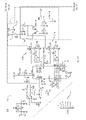
- FIG. 2 is a schematic of a circuit implementing the backup power supply according to the exemplary embodiment of the invention.
- FIG. 3 is a flowchart of an exemplary backup power supply method according to the present invention.
- FIG. 1 is a block diagram of a backup power supply 100 according to a first exemplary embodiment of the invention.
- the backup power supply provides power to a hardware power supply 102 (not part of the invention) when the main source of power 103 supplied to the hardware power supply 102 fails or is interrupted.
- the backup power supply 100 uses one or more ultra capacitors 104 to store and supply secondary power when the main power source 103 to the hardware power supply 102 is interrupted.
- the backup power supply 100 receives power from the hardware power supply over bus 105 to charge and maintain the ultra capacitors 104 in a charged state. This may be referred to as a charging cycle and will be discussed in greater detail later herein.
- the backup power supply 100 goes into a discharging cycle and supplies a secondary source of power to the hardware power supply 100 over bus 105 by discharging the one or more ultra capacitors 104 . Details regarding the components and charging and discharging processes are discussed in greater detail later herein.
- the hardware power supply 102 receives AC power from the main power source 103 , for example, a standard AC utility outlet.
- the hardware power supply 102 converts the Alternating Current (AC) power to Direct Current (DC) power that is used to supply power to the intended hardware.
- the hardware power supply 102 may provide a 12-volt bus 107 , a ground 109 , and one or more control lines 111 (collectively bus 105 ) to the backup power supply 100 .
- the control lines 111 provide the status of the main power source supply to both a backup power controller 106 and a multiphase boost converter 108 .
- the 12-volt bus 107 provides power to components of the backup power supply 100 during the charging cycle and receives power from the backup power supply 100 during the discharging cycle.
- the one or more ultra capacitors 104 are super capacitors or ultra capacitors.
- the ultra capacitors may use two sheets of aluminum foil and a separator, as is well known in the art.
- the electric charge is stored on the aluminum foil surface.
- the ultra capacitors use a structure of aluminum foil (current collector) coated with carbon powder (electric charge storage). With a surface area of up to about 2000 square meters per gram of carbon, significant charge storage is possible.
- cylindrical ultra capacitors may use the same form or size structure as chemical electrolytic capacitors.
- Exemplary ultra capacitors include “BCAP” series ultra capacitors manufactured by Maxwell Technologies of San Diego, Calif.
- Another example of an exemplary ultra capacitor includes electronic double layer capacitors manufactured by United Chemi-Con (UCC) of Rosemont, Ill.
- UCC United Chemi-Con
- the backup power controller 106 regulates the charging and discharging cycles of the one or more capacitors 104 .
- the backup power controller 106 monitors the status of both the AC power source and the charge and discharge status of the one or more ultra capacitors 104 . Based on this status information received by the backup power controller 106 , the controller 106 regulates the charging and discharging of the capacitors 104 .
- the controller 106 signals to a power charger 110 to continue to supply power from the 12-volt bus 107 to the ultra capacitors 104 , thus charging and/or maintaining the ultra capacitors 104 in a charged state. Because the ultra capacitors 104 have extremely low internal impedance, which is independent of their charged state, the alter capacitors 104 will accept as much current as the power supply provides. In addition, the ultra capacitors 104 are sensitive to voltages greater than their ratings. The power charger 110 may need to limit the voltage in a precise manner. The power charger 110 may need to be designed to a variety of conditions required by the various ultra capacitors selected.
- the controller 106 signals the multiphase boost converter 108 to start draining power from the capacitors 104 and supply power to the hardware power supply 102 via the 12-volt bus 107 .
- the multiphase boost converter 108 needs to supply a relatively constant voltage to be connected electronic equipment using the power stored in the ultra capacitors 104 that supply power over a range of voltages.
- the multiphase boost converter 108 is an efficient two-phase boost converter as discussed in the exemplary embodiment discussed later herein.
- the multiphase boost converter 108 may alternatively be a single phase or use additional phases to provide additional efficiency, for example, a four-phase boost converter may be used.
- the boost converter 108 may use a variety of designs and configurations as are apparent to an individual skilled in the art.
- An ultra capacitor 104 stores energy over an entire range of voltages; thus the energy needs to be extracted by discharging the ultra capacitor 104 to the lowest possible voltage.
- a characteristic of the boost converter 108 is that the output voltage may be greater than the input voltage.
- a “buck” type converter may be utilized, such a converter will only discharge the capacitor to the desired output voltage, which may leave unused energy in the capacitor. Due to the design of a “buck” converter, the output may have to be less than the input.
- a “buck-boost” type converter will allow the output voltage to be above and below the input voltage from the ultra capacitor.
- the “buck-boost” type converter will generally allow a greater voltage range from the capacitor.
- the “buck-boost” or a polyphase “buck-boost” converter may be limited by the design of the “buck-boost” converter.
- the backup power controller 106 also monitors the output voltage of the multiphase boost converter 108 . When the voltage output of the multiphase boost converter 108 drops below a predetermined threshold, the controller 106 may shut down the backup power supply 100 in order to avoid damage to the backup power supply 100 and/or the hardware that is being supplied with power. The controller 106 will then remain in a tripped state until reset. The reset may occur when the controller 106 receives a signal that the power supplied to the main power supply has been reestablished. Once the controller 106 is reset, the cycle of charging and discharging is continued.
- the controller 106 may also signal the hardware directly or via the hardware power supply the status of the backup power supply 100 .
- the backup power supply 100 according to the exemplary embodiment of the block diagram in FIG. 1 illustrates the backup power supply 100 as being separate from the hardware power supply 102 , however, another exemplary embodiment of the invention contemplates implementation of the backup power supply 100 and the hardware power supply as a single unit.
- the various components are grouped together for illustrative purposes according to the block diagram of FIG. 1 , the invention is not limited to the configuration of the illustrative block diagram. Components may be added, substituted or relocated to perform various tasks of the invention as described herein.
- the backup power supply circuit 200 provides backup power to a hardware power supply (not shown).
- the hardware power supply may be an ATX computer power supply or other form factor of the FX series power supplies or other hardware specific power supply.
- the hardware power supply is not limited to any specific form factor.
- the backup power supply circuit uses one or more ultra capacitors 204 to store and supply secondary power when the main power source of the hardware power supply is interrupted.
- the backup supply circuit may use four (4), 2.5 volt, 400 farad ultra capacitors in series to supply a total of 10 volts.
- the backup power supply 200 receives power from the hardware power supply to charge and maintain the ultra capacitors 204 in a charged state. This may be referred to as a charging cycle and will be discussed in greater detail later herein.
- the backup power supply 200 goes into a discharging cycle and supplies a secondary source of power to the hardware power supply by discharging the capacitors. Details regarding the components and charging and discharging processes are discussed in greater detail later herein.
- the hardware power supply provides a 12-volt bus, a ground, and one or more control lines (collectively bus 205 ) to the backup power supply 200 .
- the control lines provide the status of the main power source supply to both the backup power controller 206 and the multiphase boost converter 208 .
- the 12-volt bus provides power to components of the backup power supply 200 during the charging cycle and receives power from the backup power supply 200 during the discharging cycle.
- the backup power controller 206 regulates the charging and discharging cycles of the ultra capacitors 204 .
- the backup power controller 206 monitors the status of both the AC power source with an AC power monitoring circuit and the status of the one or more capacitors with a charge monitoring circuit. Based on this status information received by the backup power controller 206 , the controller 206 regulates the charging and discharging of the capacitors.
- the controller 206 signals to a power charger circuit 210 to continue to supply power from the 12-volt input terminal to the ultra capacitors 204 , thus charging and/or maintaining the ultra capacitors 204 in a charged state.
- the power charger circuit 210 regulates the current supplied to the ultra capacitors 204 during the charging process.
- the controller 206 signals the multiphase boost converter 208 to start draining power from the ultra capacitors 204 and supply power to the hardware power supply via the 12-volt terminal 205 .
- the multiphase boost converter 208 will supply a relatively constant voltage using the power stored in the ultra capacitors 204 that supply power over a wide range of voltages.
- the multiphase boost converter 208 is preferably a two-phase boost converter 208 with a first phase 211 a and a second phase 211 b operating 180 degrees out of phase from the first phase 211 a (although more phases are contemplated and within the scope of the invention). Thus, when Q 1 is on, Q 2 is off, and when L 1 is charging, L 2 is discharging.
- Multiphase boost converter is able to extract all or nearly all of the energy from the ultra capacitors 204 by adjusting the time or duty cycle in which each phase is left on to allow the ultra capacitor 204 to discharge.
- each phase 211 is left on for a longer period of time.
- the product of the present voltage on the ultra capacitor times time is a constant (for example, 12 volts), thus boosting whatever voltage is on the capacitor to the appropriate, desired voltage (e.g. 12 volts). This assures a constant voltage is provided to the hardware or electronics coupled to the uninterruptible power supply 200 .
- the backup power controller 206 also monitors the output voltage of the multiphase boost converter 208 with a shutoff circuit. When the voltage output of the multiphase boost converter 208 drops below a predetermined threshold, the controller 206 will shut down the backup power supply in order to avoid damage to the backup power supply and/or the hardware that is being supplied with power. The controller 206 will remain in a tripped state until reset. The reset may occur when the controller 206 receives a signal that the power supplied to the main power supply has been reestablished. Once the controller 206 is reset the cycle of charging and discharging is continued.
- the invention is not limited to the configuration of the circuit components shown in the exemplary embodiment shown in FIG. 2 . A variety of alternative and equivalent configurations (in hardware and/or firmware) for the exemplary circuit shown in FIG. 2 may be added or substituted.
- an exemplary backup power supply method 300 supplies temporary power to a device.
- the device may be, for example, a power supply, a desktop computer, a server or other processor and memory that may require a temporary source of power, a medical device or other electronic device.
- the backup power supply method is initiated when the device is activated (act 302 ). The method is not limited to being initiated by activation of the device; for example, the backup power supply may be initiated anytime a source of power is supplied to the backup power supply.
- the current in the backup power supply is regulated to provide a constant current source from main power source, which is typically AC power (act 304 ).
- the current is supplied to one or more ultra capacitors and is used to charge the capacitors to a charged state (act 306 ).
- a controller monitors the status of the main power source (act 308 ).
- the monitoring may be accomplished by a controller within the backup power supply or by a remote device that may signal the backup power supply of an actual or impending disruption of the main power.
- the disruption may be a drop in power or a spike that may require the main power supply to be interrupted.
- the backup power supply switches from a charging state to a discharging state.
- the one or more capacitors are discharged of their stored power (act 310 ).
- a multiphase boost converter uses the variable and slowly dropping voltage level supplied by the discharging ultra capacitors and boosts the dropping voltage to provide power with constant voltage that may be used by the device to which the backup power supply is connected (act 312 ).
- the device may use the backup power to perform critical functions, for example, but not limited to, shutting down operations or switching to another power source.
- the controller may also monitor the discharging voltage of the capacitors to prevent damage resulting from too low a voltage level. Once the voltage drops below a predetermined level, the backup power supply will be completely shutoff to prevent damage to the backup power supply and/or the device being supplied power. The process controller will then wait for the main power supply to re-supply the backup power supply with power or for a reset by an administrator.
- aspects of the exemplary backup power supply process may be performed by a dedicated controller within the backup power supply or by an ancillary processor that may be a part of the device being supplied power.
Abstract
Description
Claims (9)
Priority Applications (1)
| Application Number | Priority Date | Filing Date | Title |
|---|---|---|---|
| US12/473,603 US8035356B2 (en) | 2005-12-15 | 2009-05-28 | Ultra-capacitor based uninterruptible power supply |
Applications Claiming Priority (3)
| Application Number | Priority Date | Filing Date | Title |
|---|---|---|---|
| US75072005P | 2005-12-15 | 2005-12-15 | |
| US11/608,858 US20070139018A1 (en) | 2005-12-15 | 2006-12-11 | Back up power supply |
| US12/473,603 US8035356B2 (en) | 2005-12-15 | 2009-05-28 | Ultra-capacitor based uninterruptible power supply |
Related Parent Applications (1)
| Application Number | Title | Priority Date | Filing Date |
|---|---|---|---|
| US11/608,858 Continuation-In-Part US20070139018A1 (en) | 2005-12-15 | 2006-12-11 | Back up power supply |
Publications (2)
| Publication Number | Publication Date |
|---|---|
| US20090289607A1 US20090289607A1 (en) | 2009-11-26 |
| US8035356B2 true US8035356B2 (en) | 2011-10-11 |
Family
ID=41341594
Family Applications (1)
| Application Number | Title | Priority Date | Filing Date |
|---|---|---|---|
| US12/473,603 Expired - Fee Related US8035356B2 (en) | 2005-12-15 | 2009-05-28 | Ultra-capacitor based uninterruptible power supply |
Country Status (1)
| Country | Link |
|---|---|
| US (1) | US8035356B2 (en) |
Cited By (7)
| Publication number | Priority date | Publication date | Assignee | Title |
|---|---|---|---|---|
| US20100332857A1 (en) * | 2009-06-30 | 2010-12-30 | Vogman Viktor D | Reducing power losses in a redundant power supply system |
| US20140284999A1 (en) * | 2011-08-26 | 2014-09-25 | Doosan Infracore Co., Ltd | Hybrid power supply apparatus and method for controlling same |
| US20150012151A1 (en) * | 2013-07-02 | 2015-01-08 | Samsung Electronics Co., Ltd. | Power supply device, micro server having the same, and power supply method |
| US9088090B2 (en) | 2011-03-10 | 2015-07-21 | Kien Hoe Daniel Chin | Universal purpose power adapter |
| US20150280473A1 (en) * | 2014-03-26 | 2015-10-01 | Intersil Americas LLC | Battery charge system with transition control that protects adapter components when transitioning from battery mode to adapter mode |
| US9966758B2 (en) | 2012-06-11 | 2018-05-08 | Panduit Corp. | Capacitor-based UPS |
| WO2021072010A1 (en) * | 2019-10-09 | 2021-04-15 | Bae Systems Controls Inc. | Thermoelectric coolers for electronics cooling |
Families Citing this family (13)
| Publication number | Priority date | Publication date | Assignee | Title |
|---|---|---|---|---|
| US8742729B2 (en) * | 2011-06-07 | 2014-06-03 | Flashsilicon Incorporation | Rechargeable battery |
| ITRM20110610A1 (en) * | 2011-11-17 | 2013-05-18 | Eta Beta Srl | RESERVE POWER SUPPLY TO LONG LIFE SUPERCONDENSATORS |
| US8767354B1 (en) | 2011-12-08 | 2014-07-01 | Western Digital Technologies, Inc. | Data storage device employing cascaded voltage regulators during power failure |
| US9093105B2 (en) | 2011-12-09 | 2015-07-28 | Western Digital Technologies, Inc. | Disk drive charging capacitor using motor supply voltage during power failure |
| US8724422B1 (en) | 2012-02-29 | 2014-05-13 | Western Digital Technologies, Inc. | System and method for charging back-up charge storage element for data storage device using spindle phase switching elements |
| US9477250B2 (en) * | 2013-03-14 | 2016-10-25 | Bosch Automotive Service Solutions Inc. | Super capacitor and charger for secondary power having longevity features |
| CH708109B1 (en) * | 2013-08-01 | 2014-12-15 | Chypsotech Gmbh Michael Müller | Uninterruptible Power Supply (UPS) for electronic devices. |
| US8922940B1 (en) | 2014-05-27 | 2014-12-30 | Western Digital Technologies, Inc. | Data storage device reducing spindle motor voltage boost during power failure |
| FR3023019B1 (en) * | 2014-06-27 | 2016-10-21 | Bull Sas | MODULE FOR COMPENSATION OF MICROCOUPONS OF POWER SUPPLY OF A SERVER |
| US9230593B1 (en) | 2014-12-23 | 2016-01-05 | Western Digital Technologies, Inc. | Data storage device optimizing spindle motor power when transitioning into a power failure mode |
| US9355676B1 (en) | 2015-03-25 | 2016-05-31 | Western Digital Technologies, Inc. | Data storage device controlling amplitude and phase of driving voltage to generate power from a spindle motor |
| KR101778375B1 (en) | 2015-10-20 | 2017-09-14 | 엘에스산전 주식회사 | Plc system |
| US10242698B1 (en) | 2018-04-19 | 2019-03-26 | Western Digital Technologies, Inc. | Data storage device regulating BEMF power voltage during power failure |
Citations (6)
| Publication number | Priority date | Publication date | Assignee | Title |
|---|---|---|---|---|
| US5424936A (en) * | 1994-01-12 | 1995-06-13 | Deltec Corporation | Boost-input backed-up uninterrupted power supply |
| US6137280A (en) * | 1999-01-22 | 2000-10-24 | Science Applications International Corporation | Universal power manager with variable buck/boost converter |
| US20080272656A1 (en) * | 2007-05-03 | 2008-11-06 | International Business Machines Corporation | Apparatus and Method for Distributed Standby Power Provision |
| US20090201703A1 (en) * | 2008-02-07 | 2009-08-13 | Damir Klikic | Systems and Methods for Uninterruptible Power Supply Control |
| US7772720B2 (en) * | 2007-12-03 | 2010-08-10 | Spx Corporation | Supercapacitor and charger for secondary power |
| US7802121B1 (en) * | 2006-03-27 | 2010-09-21 | Network Appliance, Inc. | Auxiliary power system |
-
2009
- 2009-05-28 US US12/473,603 patent/US8035356B2/en not_active Expired - Fee Related
Patent Citations (6)
| Publication number | Priority date | Publication date | Assignee | Title |
|---|---|---|---|---|
| US5424936A (en) * | 1994-01-12 | 1995-06-13 | Deltec Corporation | Boost-input backed-up uninterrupted power supply |
| US6137280A (en) * | 1999-01-22 | 2000-10-24 | Science Applications International Corporation | Universal power manager with variable buck/boost converter |
| US7802121B1 (en) * | 2006-03-27 | 2010-09-21 | Network Appliance, Inc. | Auxiliary power system |
| US20080272656A1 (en) * | 2007-05-03 | 2008-11-06 | International Business Machines Corporation | Apparatus and Method for Distributed Standby Power Provision |
| US7772720B2 (en) * | 2007-12-03 | 2010-08-10 | Spx Corporation | Supercapacitor and charger for secondary power |
| US20090201703A1 (en) * | 2008-02-07 | 2009-08-13 | Damir Klikic | Systems and Methods for Uninterruptible Power Supply Control |
Cited By (13)
| Publication number | Priority date | Publication date | Assignee | Title |
|---|---|---|---|---|
| US10164463B2 (en) | 2009-06-30 | 2018-12-25 | Intel Corporation | Reducing power losses in a redundant power supply system |
| US9520744B2 (en) | 2009-06-30 | 2016-12-13 | Intel Corporation | Reducing power losses in a redundant power supply system |
| US9583973B2 (en) | 2009-06-30 | 2017-02-28 | Intel Corporation | Reducing power losses in a redundant power supply system |
| US20100332857A1 (en) * | 2009-06-30 | 2010-12-30 | Vogman Viktor D | Reducing power losses in a redundant power supply system |
| US9088090B2 (en) | 2011-03-10 | 2015-07-21 | Kien Hoe Daniel Chin | Universal purpose power adapter |
| US20140284999A1 (en) * | 2011-08-26 | 2014-09-25 | Doosan Infracore Co., Ltd | Hybrid power supply apparatus and method for controlling same |
| US9966758B2 (en) | 2012-06-11 | 2018-05-08 | Panduit Corp. | Capacitor-based UPS |
| US10516263B2 (en) | 2012-06-11 | 2019-12-24 | Panduit Corp. | Capacitor-based UPS |
| US20150012151A1 (en) * | 2013-07-02 | 2015-01-08 | Samsung Electronics Co., Ltd. | Power supply device, micro server having the same, and power supply method |
| US9785127B2 (en) * | 2013-07-02 | 2017-10-10 | Samsung Electronics Co., Ltd. | Power supply device, micro server having the same, and power supply method |
| US20150280473A1 (en) * | 2014-03-26 | 2015-10-01 | Intersil Americas LLC | Battery charge system with transition control that protects adapter components when transitioning from battery mode to adapter mode |
| US10797490B2 (en) * | 2014-03-26 | 2020-10-06 | Intersil Americas LLC | Battery charge system with transition control that protects adapter components when transitioning from battery mode to adapter mode |
| WO2021072010A1 (en) * | 2019-10-09 | 2021-04-15 | Bae Systems Controls Inc. | Thermoelectric coolers for electronics cooling |
Also Published As
| Publication number | Publication date |
|---|---|
| US20090289607A1 (en) | 2009-11-26 |
Similar Documents
| Publication | Publication Date | Title |
|---|---|---|
| US8035356B2 (en) | Ultra-capacitor based uninterruptible power supply | |
| US20070139018A1 (en) | Back up power supply | |
| US5572108A (en) | Power system using battery-charged capacitors | |
| US9825478B2 (en) | Method for supplying power to a load within a portable electronic device | |
| US7802121B1 (en) | Auxiliary power system | |
| US6194793B1 (en) | Apparatus and method for charging an energy storage source | |
| US8754545B2 (en) | High efficiency backup-power circuits for switch-mode power supplies | |
| KR20170018448A (en) | Engine start and battery support module | |
| EP3163712B1 (en) | Uninterruptible power-supply system | |
| JP2003244854A (en) | Charge and discharge controller for storage apparatus, charge and discharge control method, and power storage system | |
| US9590497B2 (en) | Systems and methods for capacitor charge extraction | |
| JP2007166818A (en) | Power supply system and control method thereof | |
| JP2008131736A (en) | Distributed power system and step-up/step-down chopper device | |
| JP4419093B2 (en) | Uninterruptible power supply and control method, and power storage device and method | |
| JP4006476B2 (en) | Capacitor power storage controller | |
| US20230361711A1 (en) | Method and Apparatus for Riding through Power Disruptions of a Drive Circuit | |
| JP4079108B2 (en) | Uninterruptible power system | |
| JP2008035573A (en) | Electricity accumulation device employing electric double layer capacitor | |
| JP3624531B2 (en) | Power control device, power generation device and electronic device | |
| JP2004304931A (en) | Charging method and charging device for electric storage device | |
| TWI524627B (en) | To avoid excessive discharge of the battery module power supply | |
| JP4079106B2 (en) | Uninterruptible power system | |
| JP2007043880A (en) | Capacitor pack | |
| JP4186218B2 (en) | Secondary battery pack | |
| JP2005278330A (en) | Uninterruptible power supply |
Legal Events
| Date | Code | Title | Description |
|---|---|---|---|
| AS | Assignment |
Owner name: RAM TECHNOLOGIES, LLC, CONNECTICUT Free format text: ASSIGNMENT OF ASSIGNORS INTEREST;ASSIGNOR:MENTELOS, RICHARD;REEL/FRAME:023063/0460 Effective date: 20090717 |
|
| ZAAA | Notice of allowance and fees due |
Free format text: ORIGINAL CODE: NOA |
|
| ZAAB | Notice of allowance mailed |
Free format text: ORIGINAL CODE: MN/=. |
|
| STCF | Information on status: patent grant |
Free format text: PATENTED CASE |
|
| FPAY | Fee payment |
Year of fee payment: 4 |
|
| AS | Assignment |
Owner name: MENTELOS, RICHARD, CONNECTICUT Free format text: ASSIGNMENT OF ASSIGNORS INTEREST;ASSIGNOR:RAM TECHNOLOGIES, LLC.;REEL/FRAME:039498/0090 Effective date: 20160718 |
|
| MAFP | Maintenance fee payment |
Free format text: PAYMENT OF MAINTENANCE FEE, 8TH YR, SMALL ENTITY (ORIGINAL EVENT CODE: M2552); ENTITY STATUS OF PATENT OWNER: SMALL ENTITY Year of fee payment: 8 |
|
| FEPP | Fee payment procedure |
Free format text: MAINTENANCE FEE REMINDER MAILED (ORIGINAL EVENT CODE: REM.); ENTITY STATUS OF PATENT OWNER: SMALL ENTITY |
|
| LAPS | Lapse for failure to pay maintenance fees |
Free format text: PATENT EXPIRED FOR FAILURE TO PAY MAINTENANCE FEES (ORIGINAL EVENT CODE: EXP.); ENTITY STATUS OF PATENT OWNER: SMALL ENTITY |
|
| STCH | Information on status: patent discontinuation |
Free format text: PATENT EXPIRED DUE TO NONPAYMENT OF MAINTENANCE FEES UNDER 37 CFR 1.362 |
|
| FP | Lapsed due to failure to pay maintenance fee |
Effective date: 20231011 |