US8037320B2 - Magnetic recording medium encryption - Google Patents
Magnetic recording medium encryption Download PDFInfo
- Publication number
- US8037320B2 US8037320B2 US11/695,018 US69501807A US8037320B2 US 8037320 B2 US8037320 B2 US 8037320B2 US 69501807 A US69501807 A US 69501807A US 8037320 B2 US8037320 B2 US 8037320B2
- Authority
- US
- United States
- Prior art keywords
- data
- key
- updating
- area
- encryption key
- Prior art date
- Legal status (The legal status is an assumption and is not a legal conclusion. Google has not performed a legal analysis and makes no representation as to the accuracy of the status listed.)
- Active, expires
Links
Images


Classifications
-
- H—ELECTRICITY
- H04—ELECTRIC COMMUNICATION TECHNIQUE
- H04L—TRANSMISSION OF DIGITAL INFORMATION, e.g. TELEGRAPHIC COMMUNICATION
- H04L9/00—Cryptographic mechanisms or cryptographic arrangements for secret or secure communications; Network security protocols
- H04L9/08—Key distribution or management, e.g. generation, sharing or updating, of cryptographic keys or passwords
- H04L9/0891—Revocation or update of secret information, e.g. encryption key update or rekeying
-
- H—ELECTRICITY
- H04—ELECTRIC COMMUNICATION TECHNIQUE
- H04L—TRANSMISSION OF DIGITAL INFORMATION, e.g. TELEGRAPHIC COMMUNICATION
- H04L2209/00—Additional information or applications relating to cryptographic mechanisms or cryptographic arrangements for secret or secure communication H04L9/00
- H04L2209/60—Digital content management, e.g. content distribution
Definitions
- the present invention relates to magnetic recording medium encryption, and more particularly, to re-encrypting data on a magnetic recording medium when the encryption key has been changed. While the present invention is widely applicable to various kinds of magnetic recording devices for recording data in a magnetic recording medium, it is particularly useful for a hard disk device.
- a hard disk device is a magnetic recording device used for storing information.
- information is recorded on concentric tracks present on any one of both surfaces of one or more magnetic recording disks.
- a disk is rotatably supported by a spindle motor.
- Writing information on the tracks and reading out information from the tracks are carried out by a recording/reproducing head equipped to an actuator arm.
- the actuator arm is rotated by a voice coil motor.
- the voice coil motor is excited by electric current, and causes an actuator to rotate, and the recording/reproducing head to move.
- the recording/reproducing head makes out information by sensing the change of a magnetic field from the surface of the disk.
- electric current is supplied to the recording/reproducing head.
- the electric current supplied to the recording/reproducing head cause a magnetic field to occur, which magnetizes the surface of the disk.
- the HDD password is supported by an advance technology attachment (ATA) security command, which contributes to protect data in the hard disk device.
- ATA advance technology attachment
- the HDD password may be broken by a hacker's analysis of firmware of the hard disk device and large scale integrated circuit (LSI).
- FDE Full Disk Encryption
- FDE In such a FDE, unless the encryption key is known, even if the data on the disk is directly read out, the data cannot be decrypted. Moreover, FDE has an advantage in that, even if the HDD password is broken by means of operation of firmware and LSI, the data on the disk cannot be decrypted unless the encryption key is decrypted.
- one aspect of the invention provides a system comprising: a setting module configured to set a pair of a updating source area and a reserved area for each unit of a magnetic recording medium; a reading module configured to read data encrypted using a first encryption key from the updating source area and decrypt the data using the first encryption key; a re-encryption module configured to re-encrypt the decrypted data using the second encryption key, and recording the re-encrypted data in the reserved area; and wherein, the setting module is further configured to: (a) set an area where effective user data is not recorded as a first reserved area and set a first updating source area; (b) set a second area where at least one of the first updating source area and effective user data is not recorded as a second reserved area and set a second updating source area; and (c) repeat (a) and (b) until all areas containing data encrypted using a first encryption key have been read, the data has been decrypted, the decrypted data has been re-encrypted
- Another aspect of the invention provides a method comprising: setting a pair of a updating source area and a reserved area for each unit of a magnetic recording medium; reading data encrypted using a first encryption key from the updating source area and decrypting the data using the first encryption key; re-encrypting the decrypted data using the second encryption key, and recording the re-encrypted data in the reserved area; and wherein in the setting step comprises: (a) setting an area where effective user data is not recorded as a first reserved area and setting a first updating source area; (b) setting a second area where at least of the first updating source area and effective user data is not recorded as a second reserved area and setting a second updating source area; and (c) repeating (a) and (b) until all areas containing data encrypted using a first encryption key have been read, the data has been decrypted, the decrypted data has been re-encrypted, and the re-encrypted data has been recorded.
- an additional aspect of the invention provides a computer program product readable by machine, tangibly embodying a program of instructions executable by the machine to perform a method comprising the steps of: setting a pair of a updating source area and a reserved area for each unit of a magnetic recording medium; reading data encrypted using a first encryption key from the updating source area and decrypting the data using the first encryption key; re-encrypting the decrypted data using the second encryption key, and recording the re-encrypted data in the reserved area; and wherein in the setting step comprises: (a) setting an area where effective user data is not recorded as a first reserved area and setting a first updating source area; (b) setting a second area where at least of the first updating source area and effective user data is not recorded as a second reserved area and setting a second updating source area; and (c) repeating (a) and (b) until all areas containing data encrypted using a first encryption key have been read, the data has been decrypted, the decrypted data has been re
- FIG. 1 illustrates a schematic configuration of an exemplary hard disk device applied by a magnetic recording device according to a preferred embodiment of the present invention.
- FIG. 2 illustrates one example of a matrix table.
- FIG. 3 illustrates a flowchart detailing the process for updating an encryption key.
- FIG. 4 illustrates a frame format detailing an outline of the key updating process.
- FIG. 5 illustrates a flowchart detailing the key updating process.
- FIG. 6 illustrates a flowchart detailing the key updating process when a power supply is turned on after it is shut down during the key updating process.
- FIG. 7 illustrates a schematic configuration of an exemplary hard disk device applied by a magnetic recording device according to a second preferred embodiment of the present invention.
- FIG. 8 illustrates a flowchart detailing the process for updating an encryption key according to a second preferred embodiment of the present invention.
- FIG. 9 illustrates a frame format detailing an outline of the key updating process.
- FIG. 10 illustrates a flowchart detailing the key updating process.
- FIG. 11 illustrates a flowchart detailing the key updating process when a power supply is turned on after it is shut down during the key updating process.
- FIG. 12 illustrates a configuration of an exemplary personal computer.
- modules may be implemented as a hardware circuit comprising custom VLSI circuits or gate arrays, off-the-shelf semiconductors such as logic chips, transistors, or other discrete components.
- a module may also be implemented in programmable hardware devices such as field programmable gate arrays, programmable array logic, programmable logic devices or the like.
- Modules may also be implemented in software for execution by various types of processors.
- An identified module of executable code may, for instance, comprise one or more physical or logical blocks of computer instructions which may, for instance, be organized as an object, procedure, or function. Nevertheless, the executables of an identified module need not be physically located together, but may comprise disparate instructions stored in different locations which, when joined logically together, comprise the module and achieve the stated purpose for the module.
- a module of executable code could be a single instruction, or many instructions, and may even be distributed over several different code segments, among different programs, and across several memory devices.
- operational data may be identified and illustrated herein within modules, and may be embodied in any suitable form and organized within any suitable type of data structure. The operational data may be collected as a single data set, or may be distributed over different locations including over different storage devices, and may exist, at least partially, merely as electronic signals on a system or network.
- the updating of the encryption key is performed for each track or sector of a disk, and the updating source track or sector is referred to as an “updating source area”, and the reserved track or sector of the area to be updated is referred to as a “reserved area”.
- FIG. 1 a schematic configuration example of a hard disk device applying a magnetic recording device according to the present invention is shown.
- a disk is subjected to FDE using a first encryption key KEY 1 .
- the hard disk device 10 includes a disk 11 , a SPM (Spindle Motor) 12 , a head 13 , an arm 14 , a VCM (Voice Coil Motor) 15 , a drive controller 16 , a signal processor 17 , a controller 18 , a DRAM 19 , and a ROM 20 .
- SPM Spindle Motor
- VCM Vehicle Coil Motor
- the disk 11 is a disk as a magnetic recording medium, where a various kinds of externally inputted data is recorded.
- a plurality of tracks T with a plurality of sectors S are formed on concentric circles.
- the sector usually has a size of 512 bytes, where positional information of data recorded for each sector is managed.
- the SPM 12 drives the disk 11 to rotate.
- the head 13 performs reading out and writing of signals with respect to the disk 11 .
- the arm 14 fixes and supports the head 13 .
- the VCM 15 feeds the head 13 and the arm 14 in the radial direction of the disk 11 .
- the drive controller 16 includes drive circuits for driving the SPM 12 and the VCM 15 , respectively, and performs the drive control of the SPM 12 and the VCM 15 .
- the signal processor 17 encodes the data to be written in the disk 11 and decodes the data read out from the disk 11 , and, at that time, also performs encoding by means of an error-correcting code, and processing with respect to error detection and error correction.
- the controller 18 is configured with a CPU or the like and has a function of controlling the entire operation of the hard disk device 10 . According to the firmware stored in the ROM 20 , the operation of the hard disk device 10 is controlled.
- the ROM 20 stores the firmware executed by the controller 18 .
- the DRAM 19 is used as a working area of the controller 18 and as a buffer of data read out from the disk 11 and data to be written in the disk 11 .
- the controller 18 has a function of encryption/decryption for encrypting/decrypting the data on the DRAM (buffer) 19 .
- the controller 18 constitutes an inputting/outputting circuit for sending/receiving data, controlling command, and the like between itself and host devices 30 such as a Personal Computer or an audio visual system via an interface 40 .
- the interface includes an IDE (Integrated Drive Electronics), a SCSI (Small Computer System Interface), a FC (Fiber Channel), a USB (Universal Serial Bus), or the like.
- the above mentioned controller 18 executes the below described key updating processing, and acts as: setting module configured to set a pair of the updating source track and the reserved track for each track of the disk 11 ; reading module configured to read out data encrypted using the first encryption key KEY 1 from the updating source area set by the setting module and decrypt the data using the first encryption KEY 1 ; re-encrypting module configured to reencrypt the data decrypted by the reading module using a second encryption key KEY 2 , and for recording the data in a reserved track set by the setting module; under key updating flag recording module configured to record the under key updating flag indicating whether the key updating processing is continuing or not, in the disk 11 ; and control flag recording module configured to record a control flag (CF) indicating that data is encrypted using the second encryption key, in the control flag sector (CF sector) of the reserved track, every time when writing of the data with respect to the reserved track is completed.
- setting module configured to set a pair of the updating source track and the reserved track for each track of the disk 11 ;
- FIG. 2 is a view showing one example of a matrix table associating a Logical Track (LT) with a Physical Track (PT).
- the matrix table is installed in firmware, and as shown in FIG. 2 , each of the Logical Tracks (LT) is assigned with one Physical Track (PT).
- the controller 18 changes allocation of the PT with respect to the LT to update the matrix table.
- the controller 18 Upon reception of a command (such as a writing/reading out command) issued by the host device 30 via the interface 40 , the controller 18 interprets the content, sets commands and parameters required for the drive controller 16 and the signal processor 17 , and thereby cause them to execute their operation. Being commanded to write data from the host device 30 , the controller 18 , using the first encryption key KEY 1 , encrypts the data received from the host device 30 to output to the signal processor 17 .
- a command such as a writing/reading out command
- the drive controller 16 performs drive controlling of the SPM 12 and the VCM 15 to move the head 13 with respect to a predetermined track and sector of the disk 11 .
- the signal processor 17 encodes (modulates) the data into digital bit series. Moreover, during reading out, the signal processor 17 removes high frequency noises from the read out signal, then converts the signal from an analog signal to a digital signal, and further, subjects the signal to ECC (Error Correction Code) error correction, subsequently outputs it to the controller 18 .
- ECC Error Correction Code
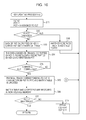
- FIG. 3 is a flowchart for explaining the procedure of the key updating processing.
- step S 1 upon reception of passwords (user password and/or master password) and a key updating command from the host device 30 (step S 1 ), the controller 18 determines whether the key is already under updating or not (step S 2 ), and when the key is already under updating (“yes” in step S 2 ), stops the key updating command (step S 8 ).
- step S 3 the controller 18 determines whether the passwords are correct or not.
- the controller 18 determines that the passwords are not correct (“No” in step S 3 )
- the controller 18 determines that the passwords are correct (“Yes” in step S 3 )
- it sets the under key updating flag recorded in the disk 11 to “1”, and generates the second encryption key (updating key) KEY 2 , then record it in the disk 11 (step S 4 ).
- step S 5 the controller 18 executes the key updating processing (refer to FIGS. 4 to 6 ) (step S 5 ).
- the controller 18 sets the under key updating flag of the disk 11 to “0”, and deletes the first encryption key (old key) KEY 1 (step S 7 ).
- FIGS. 4 and 5 are views for explaining the key updating procedures to be executed by the controller 18 .
- FIG. 4 is a frame format for explaining the outline of the key updating processing
- the FIG. 5 is a flowchart for explaining the detail of the key updating processing.
- CLT indicates Current Logical Track
- PTT Physical Target Track for new KEY
- PST Physical Source with old KEY
- the matrix table in the firmware is loaded in the DRAM 19 , and updated in the DRAM 19 , and the current values of the CLT/PTT/PST are held.
- a Physical Track where effective user data is not written is denoted as Physical Track N ⁇ 1
- Physical Tracks where user data are written are denoted as Physical Tracks N to MAX.
- User data written in Physical Tracks N to MAX is denoted as N to MAX, respectively.
- Physical Tracks N ⁇ 1 and N are set in the PTT (first reserved track) and PST (first updating source track), respectively, data N written in the Physical Track N is decrypted using the first encryption key KEY 1 , subsequently, the data N is encrypted using the second encryption key KEY 2 and then written in the Physical Track N ⁇ 1.
- CF of the CF sector in the Physical Track N ⁇ 1 is set to “2”, and LT assigned to the Physical Track N is assigned to the track N ⁇ 1, then these are recorded in the LT of the CF sector, and the matrix table is updated.
- the updating source track is set in the next reserved track, however, the next reserved track is not limited to the updating source track, another track where effective user data is not recorded may be used. Moreover, upon completion of writing data in a Physical Track, CF of the CF sector in the Physical Track is recorded, however, the CF may be recorded in the Physical Track at the same time of writing of the data in the Physical Track.
- Y is a reserved track where effective user data is not written.
- step S 12 determines whether the PTT is damaged or not.
- step S 13 another reserved track is assigned to the PTT (step S 13 ), and the procedure returns to step S 12 .
- step S 12 When the PTT is not damaged (“No” in step S 12 ), data of the PST encrypted using the first encryption key is read out, then loaded to the DRAM 19 (step S 13 ), and reencrypted using the second encryption key KEY 2 , subsequently, the data reencrypted using the second encryption key KEY 2 is written in the PTT (step S 14 ).
- the key updating processing is interrupted, then the matrix table and the CLT/PTT/PST on the DRAM 19 are recorded in the disk 11 , and waiting information indicating that the key updating processing is in a stand-by state is recorded in the disk 11 . After that the power supply is turned off. When the power supply is turned on, if the waiting information is recorded, the matrix table and the CLT/PTT/PST recorded in the disk 11 is loaded on the DRAM 19 , and the key updating processing is restarted from the interrupted processing.
- FIG. 6 is a view for explaining the key updating processing when the power supply is turned on after power shutdown has occurred during the key updating processing.
- LTP is denoted as a Lower Physical Track
- HPT is denoted as a Higher Physical Track.
- step S 21 when the device power supply is turned on, whether the under key updating flag recorded in the disk 11 is “1” or not, is determined (step S 21 ).
- the under key updating flag is not “1” (“No” in step S 21 )
- the procedure moves to an idling state (step S 29 ).
- step S 30 whether the finishing is normal or not, is determined (step S 30 ). Specifically, as described above, when the waiting information is recorded in the disk 11 , the finishing determined as being normal, and when the waiting information is not recorded, the finishing determined as being not normal.
- step S 24 whether the CPT is encrypted using the second encryption key KEY 2 or not, is determined.
- the CPT is not encrypted using the second encryption key KEY 2 (“No” in step S 24 )
- the Physical Track where the key updating processing is interrupted can be searched.
- the number of the entire Physical Tracks is MAX
- seeking should be done at log 2 (MAX) times. For example, if the number of the entire Physical Tracks is 240,000, the final Physical Track where the updating of the encryption key is completed, can be sought by 18 times of seeking (about 300 msecs.).
- the controller 18 acts as setting module configured to set a pair of an updating source track and a reserved track for each track of the magnetic recording medium; a reading module configured to read out the data encrypted using the first encryption key KEY 1 from the updating source area set by the setting module, and decrypt the data using the first encryption key KEY 1 ; and re-encrypting module configured to reencrypt the data decrypted by the reading module, using the second encryption key KEY 2 , and recording the data in the reserved area set by the setting module; where, the setting module, in the key updating processing, first, an track where effective user data is not recorded, is set as a first reserved track, and a first updating source track is set, next, the first updating source track is set as a second reserved track, and a second updating source track is set, and these steps are repeated until all tracks to be subjected to the key updating processing have been subjected to the key updating processing, when data is recorded in the disk with being encrypted using an encryption key, the encryption key can be
- the key updating processing can be restarted from the interrupted position, thereby, there is no possibility of data loss due to the power shutdown during the key updating. Additionally, even when the procedure is returned from the power shutdown during the key updating processing, in a moderate configuration without using the non-volatile memory, the key updating processing can be restarted from the interrupted position.
- the key updating processing can be executed in a higher speed.
- FIG. 7 is a view showing a configuration example of the hard disk device according to Example 2.
- components with same functions as those of FIG. 1 are denoted by same symbols, and description of common parts will be eliminated, and only different parts will de described.
- a hard disk device 10 according to this embodiment has a configuration where a non-volatile memory 21 is mounted on the hard disk device of Example 1.
- a controller 18 when key updating processing is executed, an under key updating flag, a matrix table, and CLT/PTT/PST are stored in the non-volatile memory 21 .
- Example 2 since the non-volatile memory 21 is mounted, it is not required to provide a CF sector in a disk 11 as in Example 1, enabling simplification of the key updating processing.
- FIG. 8 is a flowchart for explaining the updating procedure of an encryption key.
- steps executing similar processing as FIG. 3 will be denoted by same step numbers, the description thereof will be eliminated, and only different points will be described.
- a controller 18 when a password is determined as being correct (“Yes” in step S 3 ), an under key updating flag recorded in a non-volatile memory 21 is set to “1”, and an encryption key KEY 2 is generated, and recorded in a non-volatile memory 21 (step S 41 ).
- the controller 18 when the key updating processing is finished (“Yes” in step S 6 ), the under key updating flag in the non-volatile memory 21 is set to “0”, and a first encryption key KEY 1 in the non-volatile memory 21 is deleted (step S 42 ).
- FIGS. 9 and 10 are views for explaining the key updating processing executed by the controller 18 in this embodiment;
- FIG. 9 is a frame format for explaining the outline of the key updating processing, and
- FIG. 10 is a flowchart for explaining the detail of the key updating processing.
- Example 2 when the key updating processing is executed, a matrix table of firmware is loaded on the DRAM 19 and updated on the DRAM 19 , and the current values of CLT/PTT/PST are held on the DRAM 19 . The matrix table and the CLT/PTT/PST on the RRAM 19 are restored in the non-volatile memory 21 .
- step S 43 matrix table is updated by converting a Physical Track corresponding to CLT from PST into PTT. Then the matrix table and the CLT/PTT/PST are restored in the non-volatile memory 21 (step S 44 ).
- FIG. 11 is a view for explaining the key updating processing when a power supply is turned on.
- step S 51 when the device power supply is turned on, whether the under key updating flag in the non-volatile memory 21 is “1” or not, is determined (step S 51 ).
- the procedure moves to an idling state (step S 53 ).
- step S 53 when the under key updating flag is “1” (“Yes” in step 51 ), the procedure moves to step 12 in FIG. 10 by reading out the matrix table and the CLT/PTT/PST from the non-volatile memory 21 , then loading them on the DRAM 19 , and the key updating step is restarted from the interrupted position.
- the non-volatile memory 21 since the non-volatile memory 21 is provided, where the under key updating flag indicates whether the key updating processing is continuing or not, and the current values of the PTT (reserved track) and PST (updating source track) are recorded, even when the procedure is returned from the power shutdown during the key updating processing, the key updating processing is easily restarted from the interrupted position, resulting in no possibility of data loss due to the power shutdown during the key updating processing.
- the key updating processing is executed for each track.
- the present invention is not limited these embodiments. Rather, in a third embodiment of the invention the key updating processing may be executed for each sector and the discussion now turns to this embodiment.
- FIG. 12 is a view showing a case where the hard disk devices 10 of the above mentioned embodiments are applied to the Personal Computers.
- a personal computer 100 includes a CPU 101 ; a ROM 102 ; a RAM 103 ; a display device 104 ; an input device 105 ; a FD drive 106 executing reading/writing of data with respect to a FD 108 , a DVD/CD drive 107 reading the data of DVD/CD 109 ; a communication I/F 110 ; and a hard disk device 10 .
- the magnetic recording device according to the present invention is not limited to the hard disk devices, rather, it is applicable to another magnetic recording media for recording data for each track or sector, for example, a flexible disk, a CD-R (Compact Disk-Recordable), a DVD-R (Digital Versatile Disk-Recordable), and an optical magnetic disk.
- a flexible disk for example, a CD-R (Compact Disk-Recordable), a DVD-R (Digital Versatile Disk-Recordable), and an optical magnetic disk.
- An embodiment of the present invention may be provided as a computer program product which may include a machine-readable medium having stored thereon instructions which may be used to program a computer (or other electronic devices) to perform a process according to the any of the embodiments of the present invention.
- the machine-readable medium may include, but is not limited to, floppy diskettes, optical disks, CD-ROMs, and magneto-optical disks, ROMs, RAMs, EPROMs, EEPROMs, magnet or optical cards, or other type of media/machine-readable medium suitable for storing electronic instructions.
- an embodiment of the present invention may also be downloaded as a computer program product, wherein the program may be transferred from a remote computer to a requesting computer by way of data signals embodied in a carrier wave or other propagation medium via a communication link (e.g., a modem or network connection).
- a communication link e.g., a modem or network connection
Abstract
Description
Claims (20)
Priority Applications (2)
| Application Number | Priority Date | Filing Date | Title |
|---|---|---|---|
| US11/695,018 US8037320B2 (en) | 2007-03-31 | 2007-03-31 | Magnetic recording medium encryption |
| JP2007301918A JP4635038B2 (en) | 2007-03-31 | 2007-11-21 | Magnetic recording apparatus, encryption method, and encryption program |
Applications Claiming Priority (1)
| Application Number | Priority Date | Filing Date | Title |
|---|---|---|---|
| US11/695,018 US8037320B2 (en) | 2007-03-31 | 2007-03-31 | Magnetic recording medium encryption |
Publications (2)
| Publication Number | Publication Date |
|---|---|
| US20080240428A1 US20080240428A1 (en) | 2008-10-02 |
| US8037320B2 true US8037320B2 (en) | 2011-10-11 |
Family
ID=39794400
Family Applications (1)
| Application Number | Title | Priority Date | Filing Date |
|---|---|---|---|
| US11/695,018 Active 2030-06-10 US8037320B2 (en) | 2007-03-31 | 2007-03-31 | Magnetic recording medium encryption |
Country Status (2)
| Country | Link |
|---|---|
| US (1) | US8037320B2 (en) |
| JP (1) | JP4635038B2 (en) |
Families Citing this family (25)
| Publication number | Priority date | Publication date | Assignee | Title |
|---|---|---|---|---|
| US8307217B2 (en) * | 2007-02-02 | 2012-11-06 | Lee Lane W | Trusted storage |
| US9672333B2 (en) | 2007-05-25 | 2017-06-06 | Adobe Systems Incorporated | Trusted storage |
| US9324361B2 (en) * | 2007-08-14 | 2016-04-26 | Seagate Technology Llc | Protecting stored data from traffic analysis |
| JP2009054255A (en) * | 2007-08-29 | 2009-03-12 | Hitachi Ltd | Optical disk drive, data recording/reproducing device |
| JP5134894B2 (en) * | 2007-09-07 | 2013-01-30 | 株式会社日立製作所 | Storage apparatus and encryption key changing method |
| JP2010124213A (en) * | 2008-11-19 | 2010-06-03 | Toshiba Corp | Image forming apparatus and method of controlling the same |
| JP2010129128A (en) * | 2008-11-28 | 2010-06-10 | Toshiba Storage Device Corp | Storage apparatus, and data writing method |
| JP4648461B2 (en) * | 2009-01-30 | 2011-03-09 | 株式会社東芝 | Magnetic disk device and encryption key update method in the same |
| JP2010224644A (en) * | 2009-03-19 | 2010-10-07 | Toshiba Storage Device Corp | Control device, storage device, and data leakage preventing method |
| CN101795268B (en) | 2010-01-20 | 2014-11-05 | 中兴通讯股份有限公司 | Method and device for enhancing security of user-based security model |
| US8489893B2 (en) * | 2010-01-29 | 2013-07-16 | Hewlett-Packard Development Company, L.P. | Encryption key rotation messages written and observed by storage controllers via storage media |
| US8886962B2 (en) * | 2010-03-30 | 2014-11-11 | Lenovo (Singapore) Pte. Ltd. | Systems and methods for disk encryption with two keys |
| EP2375355A1 (en) * | 2010-04-09 | 2011-10-12 | ST-Ericsson SA | Method and device for protecting memory content |
| US8566603B2 (en) * | 2010-06-14 | 2013-10-22 | Seagate Technology Llc | Managing security operating modes |
| JP2012028860A (en) * | 2010-07-20 | 2012-02-09 | Toshiba Corp | Recording device, controller and recording device control method |
| JP4738547B2 (en) * | 2010-11-09 | 2011-08-03 | 東芝ストレージデバイス株式会社 | Storage device and data leakage prevention method |
| JP2011066925A (en) * | 2010-11-09 | 2011-03-31 | Toshiba Storage Device Corp | System and method for preventing leakage of data |
| JP2011041325A (en) * | 2010-11-09 | 2011-02-24 | Toshiba Storage Device Corp | Storage device and data leakage prevention method |
| JP4738546B2 (en) * | 2010-11-09 | 2011-08-03 | 東芝ストレージデバイス株式会社 | Data leakage prevention system and data leakage prevention method |
| JP2011040100A (en) * | 2010-11-09 | 2011-02-24 | Toshiba Storage Device Corp | System and method for prevention of data leakage |
| US8732485B2 (en) * | 2010-12-01 | 2014-05-20 | International Business Machines Corporation | Methods for process key rollover/re-encryption and systems thereof |
| US8924739B2 (en) * | 2011-01-05 | 2014-12-30 | Apple Inc. | System and method for in-place encryption |
| US8995071B2 (en) | 2012-07-17 | 2015-03-31 | International Business Machines Corporation | Monitoring of residual encrypted data to improve erase performance on a magnetic medium |
| CN106803783A (en) * | 2015-11-26 | 2017-06-06 | 深圳市中兴微电子技术有限公司 | A kind of encrypting and decrypting method, encrypting and decrypting device and data transmission system |
| US11595204B2 (en) * | 2019-06-04 | 2023-02-28 | EMC IP Holding Company LLC | Adaptive re-keying in a storage system |
Citations (6)
| Publication number | Priority date | Publication date | Assignee | Title |
|---|---|---|---|---|
| US5581740A (en) * | 1994-10-04 | 1996-12-03 | Dell Usa, L.P. | System for reading CD ROM data from hard disks |
| US5677900A (en) * | 1990-04-17 | 1997-10-14 | Sharp Kabushiki Kaisha | Method and apparatus for replacing a selected file with another longer or shorter file with no portion of the selected file remaining |
| US20020154779A1 (en) * | 2000-01-26 | 2002-10-24 | Tomoyuki Asano | Data recording/reproducing device and saved data processing method, and program proving medium |
| US7194091B2 (en) * | 2002-04-05 | 2007-03-20 | Matsushita Electric Industrial Co., Ltd. | Content using system |
| US20070288713A1 (en) * | 2004-08-26 | 2007-12-13 | Hiroshi Sugimoto | Data Recording/Reproducing Device and Method |
| US20080072071A1 (en) * | 2006-09-14 | 2008-03-20 | Seagate Technology Llc | Hard disc streaming cryptographic operations with embedded authentication |
Family Cites Families (4)
| Publication number | Priority date | Publication date | Assignee | Title |
|---|---|---|---|---|
| JPS5143908A (en) * | 1974-10-12 | 1976-04-15 | Fujitsu Ltd | JIKITEEPUSEIGYOHOSHIKI |
| JPH0778964B2 (en) * | 1990-04-17 | 1995-08-23 | シャープ株式会社 | Data recording method |
| JP2006053703A (en) * | 2004-08-11 | 2006-02-23 | Hitachi Ltd | Storage control system, and method |
| JP2007074505A (en) * | 2005-09-08 | 2007-03-22 | Seiko Epson Corp | Encryption/decryption device, electronic apparatus and encrypting/decrypting method |
-
2007
- 2007-03-31 US US11/695,018 patent/US8037320B2/en active Active
- 2007-11-21 JP JP2007301918A patent/JP4635038B2/en active Active
Patent Citations (6)
| Publication number | Priority date | Publication date | Assignee | Title |
|---|---|---|---|---|
| US5677900A (en) * | 1990-04-17 | 1997-10-14 | Sharp Kabushiki Kaisha | Method and apparatus for replacing a selected file with another longer or shorter file with no portion of the selected file remaining |
| US5581740A (en) * | 1994-10-04 | 1996-12-03 | Dell Usa, L.P. | System for reading CD ROM data from hard disks |
| US20020154779A1 (en) * | 2000-01-26 | 2002-10-24 | Tomoyuki Asano | Data recording/reproducing device and saved data processing method, and program proving medium |
| US7194091B2 (en) * | 2002-04-05 | 2007-03-20 | Matsushita Electric Industrial Co., Ltd. | Content using system |
| US20070288713A1 (en) * | 2004-08-26 | 2007-12-13 | Hiroshi Sugimoto | Data Recording/Reproducing Device and Method |
| US20080072071A1 (en) * | 2006-09-14 | 2008-03-20 | Seagate Technology Llc | Hard disc streaming cryptographic operations with embedded authentication |
Non-Patent Citations (1)
| Title |
|---|
| Technology Paper, Full Disc Encryption-Best-in-Class Data Protection, TP-541, From: Global Product Marketing, Jun. 2005, www.seagatestorage.com, Seagate Technology, LLC, Scotts Valley, California, USA. |
Also Published As
| Publication number | Publication date |
|---|---|
| US20080240428A1 (en) | 2008-10-02 |
| JP2008259170A (en) | 2008-10-23 |
| JP4635038B2 (en) | 2011-02-16 |
Similar Documents
| Publication | Publication Date | Title |
|---|---|---|
| US8037320B2 (en) | Magnetic recording medium encryption | |
| US7512812B2 (en) | Method of securely erasing data and hard disk drive using the same | |
| US8239691B2 (en) | Data storage device and management method of cryptographic key thereof | |
| US20120020474A1 (en) | Recording device, controller, control method of recording device | |
| US7827322B2 (en) | Method and apparatus for protecting data during storage/retrieval | |
| JP4648461B2 (en) | Magnetic disk device and encryption key update method in the same | |
| US7360057B2 (en) | Encryption of data in a range of logical block addresses | |
| JP4768663B2 (en) | Information processing apparatus, security system, and program executed by computer | |
| US20090106562A1 (en) | Method of protecting data saved to recording medium and data storage apparatus adopting method | |
| US5646993A (en) | Information reproducing method and apparatus having protect function and recording medium used in apparatus | |
| JP5192479B2 (en) | Disk drive and data conversion processing method in disk drive | |
| US20090175453A1 (en) | Storage apparatus and encrypted data processing method | |
| JP2008299448A (en) | Data storage device and method of updating information about encryption key | |
| US20120303970A1 (en) | Data storage apparatus, storage control apparatus and data recovery method | |
| US8090978B2 (en) | Protection of data on failing storage devices | |
| US20100149684A1 (en) | Data-storage device and analysis method for data-storage device | |
| US20100138670A1 (en) | Storage apparatus and data writing method | |
| US20050219731A1 (en) | Magnetic disk drive with a use time limiting function | |
| CN101620874A (en) | Method of checking version number of encryption information, and optical disc playback device | |
| KR100618880B1 (en) | Method for authenticating harddisk drive and recording medium therefor | |
| JP2010171806A (en) | Storage device and data falsification preventing method of storage device | |
| US9190107B2 (en) | Information recording device and information recording method | |
| JP2022144400A (en) | Magnetic disk device | |
| JP2006277815A (en) | Reproduction control circuit, integrated circuit, and information reproducing device | |
| JP2011087313A (en) | Information recording apparatus, and information recording method |
Legal Events
| Date | Code | Title | Description |
|---|---|---|---|
| AS | Assignment |
Owner name: LENOVO (SINGAPORE) PTE. LTD., SINGAPORE Free format text: ASSIGNMENT OF ASSIGNORS INTEREST;ASSIGNORS:HOBBET, JEFFREY R.;SUGAWARA, TAKASHI;YASUDA, HIROAKI;REEL/FRAME:019268/0338;SIGNING DATES FROM 20070206 TO 20070215 Owner name: LENOVO (SINGAPORE) PTE. LTD., SINGAPORE Free format text: ASSIGNMENT OF ASSIGNORS INTEREST;ASSIGNORS:HOBBET, JEFFREY R.;SUGAWARA, TAKASHI;YASUDA, HIROAKI;SIGNING DATES FROM 20070206 TO 20070215;REEL/FRAME:019268/0338 |
|
| STCF | Information on status: patent grant |
Free format text: PATENTED CASE |
|
| FEPP | Fee payment procedure |
Free format text: PAYOR NUMBER ASSIGNED (ORIGINAL EVENT CODE: ASPN); ENTITY STATUS OF PATENT OWNER: LARGE ENTITY |
|
| FPAY | Fee payment |
Year of fee payment: 4 |
|
| AS | Assignment |
Owner name: LENOVO PC INTERNATIONAL, HONG KONG Free format text: NUNC PRO TUNC ASSIGNMENT;ASSIGNOR:LENOVO (SINGAPORE) PTE LTD.;REEL/FRAME:037160/0001 Effective date: 20130401 |
|
| MAFP | Maintenance fee payment |
Free format text: PAYMENT OF MAINTENANCE FEE, 8TH YEAR, LARGE ENTITY (ORIGINAL EVENT CODE: M1552); ENTITY STATUS OF PATENT OWNER: LARGE ENTITY Year of fee payment: 8 |
|
| MAFP | Maintenance fee payment |
Free format text: PAYMENT OF MAINTENANCE FEE, 12TH YEAR, LARGE ENTITY (ORIGINAL EVENT CODE: M1553); ENTITY STATUS OF PATENT OWNER: LARGE ENTITY Year of fee payment: 12 |