US8038629B2 - Digital endotracheal tube sound acquisition and localization device - Google Patents
Digital endotracheal tube sound acquisition and localization device Download PDFInfo
- Publication number
- US8038629B2 US8038629B2 US12/244,577 US24457708A US8038629B2 US 8038629 B2 US8038629 B2 US 8038629B2 US 24457708 A US24457708 A US 24457708A US 8038629 B2 US8038629 B2 US 8038629B2
- Authority
- US
- United States
- Prior art keywords
- placement
- audio
- tube
- receiver
- proper
- Prior art date
- Legal status (The legal status is an assumption and is not a legal conclusion. Google has not performed a legal analysis and makes no representation as to the accuracy of the status listed.)
- Active, expires
Links
Images


Classifications
-
- A—HUMAN NECESSITIES
- A61—MEDICAL OR VETERINARY SCIENCE; HYGIENE
- A61B—DIAGNOSIS; SURGERY; IDENTIFICATION
- A61B7/00—Instruments for auscultation
- A61B7/02—Stethoscopes
- A61B7/04—Electric stethoscopes
-
- A—HUMAN NECESSITIES
- A61—MEDICAL OR VETERINARY SCIENCE; HYGIENE
- A61M—DEVICES FOR INTRODUCING MEDIA INTO, OR ONTO, THE BODY; DEVICES FOR TRANSDUCING BODY MEDIA OR FOR TAKING MEDIA FROM THE BODY; DEVICES FOR PRODUCING OR ENDING SLEEP OR STUPOR
- A61M16/00—Devices for influencing the respiratory system of patients by gas treatment, e.g. mouth-to-mouth respiration; Tracheal tubes
- A61M16/04—Tracheal tubes
- A61M16/0488—Mouthpieces; Means for guiding, securing or introducing the tubes
-
- A—HUMAN NECESSITIES
- A61—MEDICAL OR VETERINARY SCIENCE; HYGIENE
- A61M—DEVICES FOR INTRODUCING MEDIA INTO, OR ONTO, THE BODY; DEVICES FOR TRANSDUCING BODY MEDIA OR FOR TAKING MEDIA FROM THE BODY; DEVICES FOR PRODUCING OR ENDING SLEEP OR STUPOR
- A61M16/00—Devices for influencing the respiratory system of patients by gas treatment, e.g. mouth-to-mouth respiration; Tracheal tubes
- A61M16/04—Tracheal tubes
- A61M16/0402—Special features for tracheal tubes not otherwise provided for
- A61M16/0411—Special features for tracheal tubes not otherwise provided for with means for differentiating between oesophageal and tracheal intubation
- A61M2016/0413—Special features for tracheal tubes not otherwise provided for with means for differentiating between oesophageal and tracheal intubation with detectors of CO2 in exhaled gases
-
- A—HUMAN NECESSITIES
- A61—MEDICAL OR VETERINARY SCIENCE; HYGIENE
- A61M—DEVICES FOR INTRODUCING MEDIA INTO, OR ONTO, THE BODY; DEVICES FOR TRANSDUCING BODY MEDIA OR FOR TAKING MEDIA FROM THE BODY; DEVICES FOR PRODUCING OR ENDING SLEEP OR STUPOR
- A61M2205/00—General characteristics of the apparatus
- A61M2205/33—Controlling, regulating or measuring
- A61M2205/3375—Acoustical, e.g. ultrasonic, measuring means
Definitions
- the present invention relates to an apparatus and method for confirming proper endotracheal tube placement.
- the present invention relates to an apparatus and method for confirming proper endotracheal tube placement, where the apparatus includes a microphone and an audio signal receiver and output unit capable of receiving sound produced by squeezing a pilot balloon of the endotracheal tube filled with a mixture of a gas (such as air) and a liquid (such as water) and the method includes placing the microphone on a suprasternal notch of a patient, inserting the endotracheal tube, filling the pilot balloon with a mixture of a gas and a liquid, squeezing the balloon and analyzing the sound generated by the balloon in a digital sound acquisition and localization unit to confirm proper endotracheal tube placement.
- a gas such as air
- a liquid such as water
- the ET has a pilot balloon that communicates with the cuff on the endotracheal tube. When the pilot balloon is inflated with air/gas, it inflates the endotracheal tube cuff. This produces a seal so the chances of gastric contents entering the trachea are minimized.
- the endotracheal tube cuff can be felt in the suprasternal notch when the pilot balloon is compressed.
- United States Published Patent Application No. 20030018276 discloses a system and method for use in detecting an endotracheal tube location within a body electronically detects indigenous breath sounds emanating from a region of the body and processes the detected indigenous breath sounds to generate a parameter representative of an acoustic characteristic of the body associated with the endotracheal tube location within the body.
- the system and method generates an output indicative of the endotracheal tube location within the body based on the parameter representative of the acoustic characteristic of the body.
- the system uses a speaker to generate an input signal that is then detected by an microphone or other audio detector.
- U.S. Pat. No. 6,349,720 disclosed an endotracheal tube having an audio aid for indicating the accurate placement thereof.
- the invention comprises a cuffed ETT having distal and proximal ends, the latter having a mechanical noise-making apparatus formed thereon that provides an audible signal when air passes therethrough.
- the invention comprises the combination of a cuffed ETT having distal and proximal ends and an insertion rod for stiffening the ETT during insertion. The insertion rod is coupled to an electrically-powered noise maker formed upon the distal end thereof to produce an audible sound before air flow through the ETT is established.
- the correct placement is determined by the unaided ear hearing the noise coming from both sides of the chest. If sound is from one side only the insertion is too deep. If the sound is heard from the stomach the ETT is in the esophagus instead of trachea and should be pulled out and reinserted.
- U.S. Pat. No. 5,445,144 disclosed an apparatus and method for acoustically guiding a distal end of a tube within a body.
- the apparatus and method generates an incident sound pulse in the tube which propagates into the body, detects sound pulses resulting from the incident sound pulse and from reflected sound pulses from within the body, and processes the detected sound pulses to guide insertion of the distal end of the tube within the body.
- the apparatus and method provides an indication of the position of the distal end of the tube within the body conduit, estimates dimensions of the body conduit adjacent the distal end of the tube, and determines if the tube is obstructed.
- the present invention provides an apparatus for confirming proper endotracheal tube placement including an audio receiver such as a microphone (e.g., solid state condensed microphone, an electrocouplet microphone, etc.).
- the microphone is connected to a digital audio signal processor.
- the microphone is adapted to be placed on a patient at a site where crepitus sounds can be efficiently detected and analyzed such as placement in a suprasternal notch of a patient.
- the pilot balloon filled with a mixture of a gas (such as air) and a liquid. Proper placement can be confirmed by the audio signature produced by squeezing the pilot balloon that produces crepitus and detected by the microphone placed in the suprasternal notch or other site of the body that is capable of yielding a clear audio signal.
- the digital audio signal processor includes at least one output component designed to generate a human cognizable output, where the output component can be a speaker, a speaker with voice generation capability, a display, indicator lights, a tactile switch (a device adapted to generate a touch discernible output), vibrator, and/or any other type of output device that generates a human cognizable output.
- the output component can be a speaker, a speaker with voice generation capability, a display, indicator lights, a tactile switch (a device adapted to generate a touch discernible output), vibrator, and/or any other type of output device that generates a human cognizable output.
- the processor can also include a memory, a mass storage device, a port for an external mass storage device, communication hardware and software (wired and/or wireless) for connecting the processor to an external computer or distributed computer network such as an intranet or internet, a port for connection to a fixed or portable computer (desktop, server, personal digital assistance, or any other digital based computing device), and/or a port for connection to a hard copy output device.
- the present invention also provides method including the step of placing a receiver of this invention at a site on a patient where crepitus sounds can be efficiently detected and analyzed such as placing the receive in a suprasternal notch of a patient.
- a receiver of this invention Once the receiver is in place, an endotracheal tube having a pilot balloon is inserted into the patient.
- the balloon is filled with a mixture of a gas (such as air) and a liquid and is adapted to generate a well characterized sound when squeezed.
- a gas such as air
- squeezing the balloon produces the sound which is detected by the receiver as an audio signal.
- the received audio signal is then forwarded to an audio signal processor in electrical communication with the receiver.
- the processed signal is then analyzed to determine if the signal conforms to a signal corresponding to a proper placement of the tube in the patient.
- the processor can output the signal via an output component concurrent or after determination. If the signal does not indicate proper placement either based on the output signal directly or from the processor determination, then the tube can be repositioned until the proper signal is detected, analyzed and determined.
- FIGS. 1A&B depict an embodiment of an apparatus to confirm proper placement of an endotracheal tube in a patient.
- FIGS. 2A&B depict another embodiment of an apparatus to confirm proper placement of an endotracheal tube in a patient.
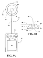
- FIGS. 3A&B depict another embodiment of an apparatus to confirm proper placement of an endotracheal tube in a patient.
- FIGS. 4A&B depict another embodiment of an apparatus to confirm proper placement of an endotracheal tube in a patient.
- FIG. 5 depicts a compact embodiment of an apparatus to confirm proper placement of an endotracheal tube in a patient.
- FIG. 6 depicts another compact embodiment of an apparatus to confirm proper placement of an endotracheal tube in a patient.
- FIG. 7 depicts another compact embodiment of an apparatus to confirm proper placement of an endotracheal tube in a patient.
- FIG. 8 depicts another compact embodiment of an apparatus to confirm proper placement of an endotracheal tube in a patient.
- an apparatus and an associated method can be constructed and implemented for confirming proper placement of an endotracheal tube in a patient whenever an endotracheal tube is required such as when a patient if undergoing a medical procedure requiring general anesthesia, has an obstructed breathing pathways, or is in need of ventilation.
- Proper endotracheal tube placement is critical to patient health and safety for improper placement can lead to serious complications including death.
- the inventors have found that by filling a pilot balloon of an endotracheal tube with a mixture of a gas and a liquid, the sound produced by the balloon as it is squeezed can be used to determine proper endotracheal tube placement.
- the inventors have found that the sound from the balloon can be used to distinguish between a properly placed endotracheal tube and improperly placed tube.
- the inventors have also found that the sound from the balloon can be used to determine the type of improper placement including placement in the esophagus or placement that ventilates only one lung.
- the inventors have found that the sound can be detected efficiently via a microphone disposed on the patient at a site sufficient to clearly detect the sound, a crepitus produced by air bubbles moving through the liquid of the gas/liquid mixture used to fill the balloon.
- the inventors have found that if the tube is placed in the esophagus, the crepitus is not heard well as there is a column of air in the trachea interposed between the microphone and the ballon—air is a bad conductor of sound.
- the sound detected if the tube ventilates only one lung is also distinct from the sound produced by a properly positioned endotracheal tube.
- the present invention broadly relates to an apparatus for confirming proper endotracheal tube placement including an endotracheal tube having a pilot balloon filled with a gas air mixture.
- the apparatus also includes an audio or acoustic detection system and optionally an audio analyzer system.
- the audio detection system includes an audio microphone or other audio sensing device capable of detecting audio frequencies in a range corresponding to a sound generated by the pilot balloon when it is squeezed and release one or more times.
- the audio detector system also includes an audio sound card capable of receiving and amplifying the sound in a digital format. The sound in digital format can then be played, displayed or reproduced for touch. The sound in digital format can also be analyzed to determine if it is consistent with proper endotracheal tube placement or improper placement.
- the apparatus can also include output devices to inform an user if endotracheal tube placement in proper or improper in a variety of different display formats.
- the apparatus can be comprise two or more substantially separate components or can be a single component.
- the present invention also broadly relates to method for making and using same. Different embodiments of the apparatus are described more fully in the detailed description of the drawings section.
- the sound of air bubbles in a balloon filled with a gas/liquid mixture is a useful tool for well trained practitioners to determine proper endotracheal tube.
- the technique depends on the practitioner.
- the inventors have designed a specialized medical apparatus adapted to allow all medical personnel including highly trained doctors and nurses to emergency medical personnel, military medical personnel, and first responders to quickly and reliably determine proper endotracheal tube placement in a non-invasive method.
- the that includes an audio bell including a microphone capable of detecting an audio signal generated by the tracheal crepitus, which occurs within a given frequency range.
- the apparatus also includes an audio processor adapted to receive the audio signal detected from the microphone and analyze the signal. The signal analysis gives rise to a straight forward way to confirm proper endotracheal tube placement. Besides the anesthesiologists, nurse anesthesiologists, anesthesiologists in training, or other medical personnel will be able to use the apparatus to confirm proper endotracheal tube placement.
- Such a medical instrument will have application: 1) during medical emergencies in the field administered by paramedics or other medical professionals and 2) during medical emergencies in military theaters where night medical operation or operation with limited light are performed.
- the medical apparatuses of this invention and the associated methods are ideal for endotracheal tube localization to determine and confirm proper endotracheal tube placement before the first breath is given.
- Such apparatuses and methods are capable of reducing or preventing gastric insufflation and regurgitation of gastric content.
- the apparatus of this invention is not an electronic stethoscope. It does not electronically filter nor enhance the audio signal beyond the normal range of human hearing.
- the apparatus is unique in its use of a high-fidelity microphone and signal processor having a 24-bit-48 khz sampling rate, which was not achievable with off-the-shelf components until recent year.
- the heart of the system is the sum of an excellent response and fidelity of an electrocouplet microphone picking up sound from a high quality audio receiver such as the head of a high quality stethoscope.
- Suitable stethoscopes includes stethoscopes made by Littman.
- Suitable high-fidelity and large sampling rate audio processor include an Audigy 2 Z95 soundblaster card made by Creative Inc.
- the audio components are all adapted to determine the sound characteristics of endotracheal tube tubes in tracheal positions and esophageal positions.
- the signal picked up from the crepitus is filtered through a specialized frequency window specifically designed to confirm the placement of the endotracheal tube.
- This device will have further development potential once the sound characteristics for endotracheal tube placement have been documented and approved by peer-based review such as the ASA or APSF (Anesthesia Patient Safety Foundation).
- An embodiment of this invention includes a Littman Cardiology II stethoscope having the ear part cut off leaving a 120 mm length of tubing.
- the dual lumen chamber of the stethoscope bell receiver was sliced into a single orifice having a diameter of 12 mm.
- the inventors mounted an electrocouplet microphone having a frequency response of 70-16,000 Hz with an inline battery amplification and impedence of 1000 Ohms ⁇ 20% at 1000 Hz and sensitivity of ⁇ 65 dB ⁇ 3 dB at 1000 Hz.
- the microphone includes a 1.37 mm cord having a 2 mm diameter and ending with a 3.5 mm standard audio jack.
- the first 112 mm of remaining ear part tube was filed or encased in low-density foam to dampen excess vibration resulting from rubbing and external noise influence on the tube before the electrocouplet microphone pick-up.
- Artifact can be introduced by rubbing of tube especially as the patient inhales or exhales, cardiac or thoracic fasciculations, hyperthermic shake, external noise from talking, breathing, and etc.
- the foam isolates the sound within the tube in the noisy operating room environment.
- the microphone is then plugged into a Soundblaster Audigy 2 Z95 notebook audio card with 24 bit-48 kHz sampling available from Creative Inc. and recorded using standard lossless “.wav” file extension without the use of an audio compression or a filter to maintain fidelity and clarity of sound.
- an embodiment of an apparatus of this invention is shown to include an audio receiving unit 102 having a body 104 .
- an audio receiver 108 such as a microphone.
- the receiver 108 is designed to come into contact with the skin of the patient.
- a fluid such as the fluid used in ultrasound can be used to improve audio contact between the receiver and the skin.
- the apparatus 100 also includes a signal cable 130 connected at a first end 132 to the receiver 108 and at a second end 134 to an audio processing unit 150 .
- the processing unit 150 include a housing 152 .
- the processing unit 152 can include one or more of a visual display component 154 , a speaker 156 , a tactile component 158 or indicator lights 160 .
- the visual display component 154 is adapted to produce a visual image corresponding to the received audio signal and an analysis of whether the received audio signal evidences a proper tube placement.
- the visual display can be a display of the received signal relative to a signal from a properly placed tube or a display of the received signal and a message indicated proper or improper placement.
- the speaker 156 is adapted to produce an audio signal either corresponding to the received audio signal or to produce an indication that the signal corresponds either to a proper or improper placement of the tube such as a voice saying good or bad placement.
- the tactile component 158 is adapted to produce touch cognizable pulses to indicate proper or improper tube placement.
- the indicator lights 160 are adapted to produce lights indicating proper or improper tube placement.
- the processing unit 150 can include all of any combination of these output components. Moreover, each output component can be designed not only to evidence proper tube placement, but to also evidence the nature of the improper tube placement such as placement in the esophagus, a placement ventilating a single lung, a placement with an improper seal, etc.
- an embodiment of an apparatus of this invention is shown to include an audio receiving unit 202 having a body 204 .
- a receiver 208 In a center 206 of the body is mounted a receiver 208 .
- the receiving unit 202 also includes an audio cavity 210 .
- the receiving unit 202 may also include a diaphragm 212 so that the cavity 210 is defined between the diaphragm 212 and the receiver 208 .
- the apparatus 200 also includes a signal cable 230 connected at a first end 232 to the microphone 108 and at a second end 234 to an audio processing unit 250 .
- the processing unit 250 include a housing 252 .
- the processing unit 252 can include one or more of a visual display component 254 , a speaker 256 , a tactile component 258 or indicator lights 260 .
- the visual display component 254 is adapted to produce a visual image corresponding to the received audio signal and an analysis of whether the received audio signal evidences a proper tube placement.
- the visual display can be a display of the received signal relative to a signal from a properly placed tube or a display of the received signal and a message indicated proper or improper placement.
- the speaker 256 is adapted to produce an audio signal either corresponding to the received audio signal or to produce an indication that the signal corresponds either to a proper or improper placement of the tube such as a voice saying good or bad placement.
- the tactile component 258 is adapted to produce touch cognizable pulses to indicate proper or improper tube placement.
- the indicator lights 260 are adapted to produce lights indicating proper or improper tube placement.
- the processing unit 250 can include all of any combination of these output components. Moreover, each output component can be designed not only to evidence proper tube placement, but to also evidence the nature of the improper tube placement such as placement in the esophagus, a placement ventilating a single lung, a placement with an improper seal, etc.
- an embodiment of an apparatus of this invention is shown to include an audio receiving unit 302 having a body 304 .
- the receiving unit 302 also includes an acoustic cavity 310 having an acoustic channel 314 .
- a receiver 308 In a center 306 of the channel 316 is mounted a receiver 308 .
- the receiving unit 302 may also include a diaphragm 312 so that the cavity 310 is defined between the diaphragm 312 and the receiver 308 .
- the apparatus 300 also includes a signal cable 330 connected at a first end 332 to the microphone 308 and at a second end 334 to an audio processing unit 350 .
- the processing unit 350 include a housing 352 .
- the processing unit 352 can include one or more of a visual display component 354 , a speaker 356 , a tactile component 358 or indicator lights 360 .
- the visual display component 354 is adapted to produce a visual image corresponding to the received audio signal and an analysis of whether the received audio signal evidences a proper tube placement.
- the visual display can be a display of the received signal relative to a signal from a properly placed tube or a display of the received signal and a message indicated proper or improper placement.
- the speaker 356 is adapted to produce an audio signal either corresponding to the received audio signal or to produce an indication that the signal corresponds either to a proper or improper placement of the tube such as a voice saying good or bad placement.
- the tactile component 358 is adapted to produce touch cognizable pulses to indicate proper or improper tube placement.
- the indicator lights 360 are adapted to produce lights indicating proper or improper tube placement.
- the processing unit 350 can include all of any combination of these output components. Moreover, each output component can be designed not only to evidence proper tube placement, but to also evidence the nature of the improper tube placement such as placement in the esophagus, a placement ventilating a single lung, a placement with an improper seal, etc.
- an embodiment of an apparatus of this invention is shown to include an audio receiving unit 402 having a body 404 .
- the receiving unit 402 also includes an acoustic cavity 410 having an acoustic channel 414 .
- the receiving unit 402 may also include a diaphragm 412 so that the cavity 410 is defined between the diaphragm 412 and the channel 414 .
- the apparatus 400 also includes a tube 416 extending out from the channel 414 . In a distal end 406 of the tube 416 is mounted a receiver 408 .
- the tube 414 may optionally be surrounded by a low-density foam 418 to reduce acoustic artifacts from the patient and/or the operating room.
- the apparatus 400 also includes a signal cable 430 connected at a first end 432 to the receiver 408 and at a second end 434 to an audio processing unit 450 .
- the processing unit 450 include a housing 452 .
- the processing unit 452 can include one or more of a visual display component 454 , a speaker 456 , a tactile component 458 or indicator lights 460 .
- the visual display component 454 is adapted to produce a visual image corresponding to the received audio signal and an analysis of whether the received audio signal evidences a proper tube placement.
- the visual display can be a display of the received signal relative to a signal from a properly placed tube or a display of the received signal and a message indicated proper or improper placement.
- the speaker 456 is adapted to produce an audio signal either corresponding to the received audio signal or to produce an indication that the signal corresponds either to a proper or improper placement of the tube such as a voice saying good or bad placement.
- the tactile component 458 is adapted to produce touch cognizable pulses to indicate proper or improper tube placement.
- the indicator lights 460 are adapted to produce lights indicating proper or improper tube placement.
- the processing unit 450 can include all of any combination of these output components. Moreover, each output component can be designed not only to evidence proper tube placement, but to also evidence the nature of the improper tube placement such as placement in the esophagus, a placement ventilating a single lung, a placement with an improper seal, etc.
- a compact embodiment of an apparatus of this invention is shown to include an audio receiving unit 502 having a oval shaped body 504 .
- an audio receiver 508 In a center 506 of the body 504 is mounted an audio receiver 508 .
- the receiver 508 In this embodiment 500 , the receiver 508 is designed to come into contact with the skin of the patient.
- a fluid such as the fluid used in ultrasound can be used to improve audio contact between the receiver and the skin.
- the apparatus 500 also includes a signal cable 530 connected at a first end 532 to the receiver 508 and at a second end 534 to an audio processing unit 550 .
- the processing unit 550 include a housing 552 .
- the processing unit 552 can include one or more of a visual display component 554 , a speaker 556 , a tactile component 558 or indicator lights 560 .
- the visual display component 554 is adapted to produce a visual image corresponding to the received audio signal and an analysis of whether the received audio signal evidences a proper tube placement.
- the visual display can be a display of the received signal relative to a signal from a properly placed tube or a display of the received signal and a message indicated proper or improper placement.
- the speaker 556 is adapted to produce an audio signal either corresponding to the received audio signal or to produce an indication that the signal corresponds either to a proper or improper placement of the tube such as a voice saying good or bad placement.
- the tactile component 558 is adapted to produce touch cognizable pulses to indicate proper or improper tube placement.
- the indicator lights 560 are adapted to produce lights indicating proper or improper tube placement.
- the processing unit 550 can include all of any combination of these output components. Moreover, each output component can be designed not only to evidence proper tube placement, but to also evidence the nature of the improper tube placement such as placement in the esophagus, a placement ventilating a single lung, a placement with an improper seal, etc.
- FIG. 6 another compact embodiment of an apparatus of this invention, generally 600 , is shown to include an audio receiving unit 602 having a oval shaped body 604 .
- an audio receiver 608 In a center 606 of the body 604 is mounted an audio receiver 608 .
- the receiver 608 In this embodiment 600 , the receiver 608 is designed to come into contact with the skin of the patient.
- a fluid such as the fluid used in ultrasound can be used to improve audio contact between the receiver and the skin.
- the apparatus 600 also includes a signal cable 630 connected at a first end 632 to the receiver 608 and at a second end 634 to an audio processing unit 650 .
- the processing unit 650 include a housing 652 .
- the processing unit 652 can include one or more of a visual display component 654 , a speaker 656 , a tactile component 658 or indicator lights 660 .
- the visual display component 654 is adapted to produce a visual image corresponding to the received audio signal and an analysis of whether the received audio signal evidences a proper tube placement.
- the visual display can be a display of the received signal relative to a signal from a properly placed tube or a display of the received signal and a message indicated proper or improper placement.
- the speaker 656 is adapted to produce an audio signal either corresponding to the received audio signal or to produce an indication that the signal corresponds either to a proper or improper placement of the tube such as a voice saying good or bad placement.
- the tactile component 658 is adapted to produce touch cognizable pulses to indicate proper or improper tube placement.
- the indicator lights 660 are adapted to produce lights indicating proper or improper tube placement.
- the processing unit 650 can include all of any combination of these output components. Moreover, each output component can be designed not only to evidence proper tube placement, but to also evidence the nature of the improper tube placement such as placement in the esophagus, a placement ventilating a single lung, a placement with an improper seal, etc.
- the processing unit 650 is connected to the receiving unit 602 via a connecting rod or shaft 662 having two ball 664 and 666 disposed on each end.
- One ball 664 is adapted to be received into a socket 668 disposed in a proximal end 670 of the receiving body 602 .
- the second ball 666 is adapted to be received into a second socket 672 disposed in a proximal end 674 of the processing body 652 .
- the shaft 662 , the two balls 664 and 666 and the two sockets 668 and 672 are designed to allow the processing unit 650 to be swivelled relative to the receiving unit 602 to a convenient position for viewing, hearing or touching.
- a compact embodiment of an apparatus of this invention is shown to include an audio receiving unit 702 having a oval shaped body 704 .
- an audio receiver 708 In a center 706 of the body 704 is mounted an audio receiver 708 .
- the receiving unit 702 also includes an audio cavity 710 .
- the receiving unit 702 may also include a diaphragm 712 so that the cavity 710 is defined between the diaphragm 712 and the receiver 708 .
- the apparatus 700 also includes a signal cable 730 connected at a first end 732 to the receiver 708 and at a second end 734 to an audio processing unit 750 .
- the processing unit 750 include a housing 752 .
- the processing unit 752 can include one or more of a visual display component 754 , a speaker 756 , a tactile component 758 or indicator lights 760 .
- the visual display component 754 is adapted to produce a visual image corresponding to the received audio signal and an analysis of whether the received audio signal evidences a proper tube placement.
- the visual display can be a display of the received signal relative to a signal from a properly placed tube or a display of the received signal and a message indicated proper or improper placement.
- the speaker 756 is adapted to produce an audio signal either corresponding to the received audio signal or to produce an indication that the signal corresponds either to a proper or improper placement of the tube such as a voice saying good or bad placement.
- the tactile component 758 is adapted to produce touch cognizable pulses to indicate proper or improper tube placement.
- the indicator lights 760 are adapted to produce lights indicating proper or improper tube placement.
- the processing unit 750 can include all of any combination of these output components. Moreover, each output component can be designed not only to evidence proper tube placement, but to also evidence the nature of the improper tube placement such as placement in the esophagus, a placement ventilating a single lung, a placement with an improper seal, etc.
- FIG. 8 another compact embodiment of an apparatus of this invention, generally 800 , is shown to include an audio receiving unit 802 having a oval shaped body 804 .
- an audio receiving unit 802 having a oval shaped body 804 .
- the receiving unit 802 also includes an audio cavity 810 .
- the receiving unit 802 may also include a diaphragm 812 so that the cavity 810 is defined between the diaphragm 812 and the receiver 808 .
- the apparatus 800 also includes a signal cable 830 connected at a first end 832 to the receiver 808 and at a second end 834 to an audio processing unit 850 .
- the processing unit 850 include a housing 852 .
- the processing unit 852 can include one or more of a visual display component 854 , a speaker 856 , a tactile component 858 or indicator lights 860 .
- the visual display component 854 is adapted to produce a visual image corresponding to the received audio signal and an analysis of whether the received audio signal evidences a proper tube placement.
- the visual display can be a display of the received signal relative to a signal from a properly placed tube or a display of the received signal and a message indicated proper or improper placement.
- the speaker 856 is adapted to produce an audio signal either corresponding to the received audio signal or to produce an indication that the signal corresponds either to a proper or improper placement of the tube such as a voice saying good or bad placement.
- the tactile component 858 is adapted to produce touch cognizable pulses to indicate proper or improper tube placement.
- the indicator lights 860 are adapted to produce lights indicating proper or improper tube placement.
- the processing unit 850 can include all of any combination of these output components. Moreover, each output component can be designed not only to evidence proper tube placement, but to also evidence the nature of the improper tube placement such as placement in the esophagus, a placement ventilating a single lung, a placement with an improper seal, etc.
- the processing unit 850 is connected to the receiving unit 802 via a connecting rod or shaft 862 having two ball 864 and 866 disposed on each end.
- One ball 864 is adapted to be received into a socket 868 disposed in a proximal end 870 of the receiving body 802 .
- the second ball 866 is adapted to be received into a second socket 872 disposed in a proximal end 874 of the processing body 852 .
- the shaft 862 , the two balls 864 and 866 and the two sockets 868 and 872 are designed to allow the processing unit 850 to be swivelled relative to the receiving unit 802 to a convenient position for viewing, hearing or touching.
Abstract
An apparatus and method for determining proper endotreachal placement is disclosed. The apparatus includes an audio receiver having a body, a microphone mount in a center thereof the body and an audio cavity, an audio processing unit; and a signal cable connected at a first end to the microphone and at a second end, where the receiver is adapted to be positioned in a suprasternal notch of a patient and the acoustic signal detected after inflation of a balloon associated with an endotracheal tube. The method uses the apparatus to detect and analyze an audio signal. The audio signal is then used to confirm endotracheal tube placement.
Description
This application claim priority to and the benefit of U.S. Provisional Application Ser. No. 60/977,034, filed Oct. 2, 2007.
1. Field of the Invention
The present invention relates to an apparatus and method for confirming proper endotracheal tube placement.
More particularly, the present invention relates to an apparatus and method for confirming proper endotracheal tube placement, where the apparatus includes a microphone and an audio signal receiver and output unit capable of receiving sound produced by squeezing a pilot balloon of the endotracheal tube filled with a mixture of a gas (such as air) and a liquid (such as water) and the method includes placing the microphone on a suprasternal notch of a patient, inserting the endotracheal tube, filling the pilot balloon with a mixture of a gas and a liquid, squeezing the balloon and analyzing the sound generated by the balloon in a digital sound acquisition and localization unit to confirm proper endotracheal tube placement.
2. Description of the Related Art
The most important job an anesthesiologist does is to place an endotracheal tube (ET) in the trachea when general anesthesia with a secure airway is indicated. The inability to place the ET in the trachea or to misplace the ET in the esophagus can lead to disastrous results and even death. The ET has a pilot balloon that communicates with the cuff on the endotracheal tube. When the pilot balloon is inflated with air/gas, it inflates the endotracheal tube cuff. This produces a seal so the chances of gastric contents entering the trachea are minimized. The endotracheal tube cuff can be felt in the suprasternal notch when the pilot balloon is compressed. Presently there are three ways to confirm proper placement of the endotracheal tube: (1) water vapor mist in the endotracheal tube; (2) auscultation of bilateral breath sounds when oxygen or air is deliver through a reservoir bag or Ambu bag; and (3) detection of carbon dioxide either on a capnograph or a disposable CO2 monitor, which is today considered the gold standard by the American Association of Anesthesiologists. But none of these methods are 100% confirmatory.
United States Published Patent Application No. 20030018276 discloses a system and method for use in detecting an endotracheal tube location within a body electronically detects indigenous breath sounds emanating from a region of the body and processes the detected indigenous breath sounds to generate a parameter representative of an acoustic characteristic of the body associated with the endotracheal tube location within the body. The system and method generates an output indicative of the endotracheal tube location within the body based on the parameter representative of the acoustic characteristic of the body. The system uses a speaker to generate an input signal that is then detected by an microphone or other audio detector.
U.S. Pat. No. 6,349,720 disclosed an endotracheal tube having an audio aid for indicating the accurate placement thereof. In a first preferred embodiment, the invention comprises a cuffed ETT having distal and proximal ends, the latter having a mechanical noise-making apparatus formed thereon that provides an audible signal when air passes therethrough. In a second preferred embodiment, the invention comprises the combination of a cuffed ETT having distal and proximal ends and an insertion rod for stiffening the ETT during insertion. The insertion rod is coupled to an electrically-powered noise maker formed upon the distal end thereof to produce an audible sound before air flow through the ETT is established. In both embodiments the correct placement is determined by the unaided ear hearing the noise coming from both sides of the chest. If sound is from one side only the insertion is too deep. If the sound is heard from the stomach the ETT is in the esophagus instead of trachea and should be pulled out and reinserted.
U.S. Pat. No. 5,445,144 disclosed an apparatus and method for acoustically guiding a distal end of a tube within a body. The apparatus and method generates an incident sound pulse in the tube which propagates into the body, detects sound pulses resulting from the incident sound pulse and from reflected sound pulses from within the body, and processes the detected sound pulses to guide insertion of the distal end of the tube within the body. The apparatus and method provides an indication of the position of the distal end of the tube within the body conduit, estimates dimensions of the body conduit adjacent the distal end of the tube, and determines if the tube is obstructed.
Although these methods and their associated apparatus are known, there is still an need in the art for apparatuses and methods that improve the ability to confirm proper ET placement.
The present invention provides an apparatus for confirming proper endotracheal tube placement including an audio receiver such as a microphone (e.g., solid state condensed microphone, an electrocouplet microphone, etc.). The microphone is connected to a digital audio signal processor. The microphone is adapted to be placed on a patient at a site where crepitus sounds can be efficiently detected and analyzed such as placement in a suprasternal notch of a patient. After the placement of the tube, the pilot balloon filled with a mixture of a gas (such as air) and a liquid. Proper placement can be confirmed by the audio signature produced by squeezing the pilot balloon that produces crepitus and detected by the microphone placed in the suprasternal notch or other site of the body that is capable of yielding a clear audio signal. The digital audio signal processor includes at least one output component designed to generate a human cognizable output, where the output component can be a speaker, a speaker with voice generation capability, a display, indicator lights, a tactile switch (a device adapted to generate a touch discernible output), vibrator, and/or any other type of output device that generates a human cognizable output. The processor can also include a memory, a mass storage device, a port for an external mass storage device, communication hardware and software (wired and/or wireless) for connecting the processor to an external computer or distributed computer network such as an intranet or internet, a port for connection to a fixed or portable computer (desktop, server, personal digital assistance, or any other digital based computing device), and/or a port for connection to a hard copy output device.
The present invention also provides method including the step of placing a receiver of this invention at a site on a patient where crepitus sounds can be efficiently detected and analyzed such as placing the receive in a suprasternal notch of a patient. Once the receiver is in place, an endotracheal tube having a pilot balloon is inserted into the patient. The balloon is filled with a mixture of a gas (such as air) and a liquid and is adapted to generate a well characterized sound when squeezed. After initial tube placement and inflating the pilot balloon with the gas/liquid mixture, squeezing the balloon produces the sound which is detected by the receiver as an audio signal. The received audio signal is then forwarded to an audio signal processor in electrical communication with the receiver. The processed signal is then analyzed to determine if the signal conforms to a signal corresponding to a proper placement of the tube in the patient. The processor can output the signal via an output component concurrent or after determination. If the signal does not indicate proper placement either based on the output signal directly or from the processor determination, then the tube can be repositioned until the proper signal is detected, analyzed and determined.
The invention can be better understood with reference to the following detailed description together with the appended illustrative drawings in which like elements are numbered the same.
The inventors have found that an apparatus and an associated method can be constructed and implemented for confirming proper placement of an endotracheal tube in a patient whenever an endotracheal tube is required such as when a patient if undergoing a medical procedure requiring general anesthesia, has an obstructed breathing pathways, or is in need of ventilation. Proper endotracheal tube placement is critical to patient health and safety for improper placement can lead to serious complications including death. The inventors have found that by filling a pilot balloon of an endotracheal tube with a mixture of a gas and a liquid, the sound produced by the balloon as it is squeezed can be used to determine proper endotracheal tube placement. The inventors have found that the sound from the balloon can be used to distinguish between a properly placed endotracheal tube and improperly placed tube. The inventors have also found that the sound from the balloon can be used to determine the type of improper placement including placement in the esophagus or placement that ventilates only one lung. The inventors have found that the sound can be detected efficiently via a microphone disposed on the patient at a site sufficient to clearly detect the sound, a crepitus produced by air bubbles moving through the liquid of the gas/liquid mixture used to fill the balloon. The inventors have found that if the tube is placed in the esophagus, the crepitus is not heard well as there is a column of air in the trachea interposed between the microphone and the ballon—air is a bad conductor of sound. The sound detected if the tube ventilates only one lung is also distinct from the sound produced by a properly positioned endotracheal tube.
The present invention broadly relates to an apparatus for confirming proper endotracheal tube placement including an endotracheal tube having a pilot balloon filled with a gas air mixture. The apparatus also includes an audio or acoustic detection system and optionally an audio analyzer system. The audio detection system includes an audio microphone or other audio sensing device capable of detecting audio frequencies in a range corresponding to a sound generated by the pilot balloon when it is squeezed and release one or more times. The audio detector system also includes an audio sound card capable of receiving and amplifying the sound in a digital format. The sound in digital format can then be played, displayed or reproduced for touch. The sound in digital format can also be analyzed to determine if it is consistent with proper endotracheal tube placement or improper placement. The apparatus can also include output devices to inform an user if endotracheal tube placement in proper or improper in a variety of different display formats. The apparatus can be comprise two or more substantially separate components or can be a single component. The present invention also broadly relates to method for making and using same. Different embodiments of the apparatus are described more fully in the detailed description of the drawings section.
Clinically, the sound of air bubbles in a balloon filled with a gas/liquid mixture is a useful tool for well trained practitioners to determine proper endotracheal tube. However, the technique depends on the practitioner. The inventors have designed a specialized medical apparatus adapted to allow all medical personnel including highly trained doctors and nurses to emergency medical personnel, military medical personnel, and first responders to quickly and reliably determine proper endotracheal tube placement in a non-invasive method.
The that includes an audio bell including a microphone capable of detecting an audio signal generated by the tracheal crepitus, which occurs within a given frequency range. The apparatus also includes an audio processor adapted to receive the audio signal detected from the microphone and analyze the signal. The signal analysis gives rise to a straight forward way to confirm proper endotracheal tube placement. Besides the anesthesiologists, nurse anesthesiologists, anesthesiologists in training, or other medical personnel will be able to use the apparatus to confirm proper endotracheal tube placement. Such a medical instrument will have application: 1) during medical emergencies in the field administered by paramedics or other medical professionals and 2) during medical emergencies in military theaters where night medical operation or operation with limited light are performed. The medical apparatuses of this invention and the associated methods are ideal for endotracheal tube localization to determine and confirm proper endotracheal tube placement before the first breath is given. Such apparatuses and methods are capable of reducing or preventing gastric insufflation and regurgitation of gastric content.
The apparatus of this invention is not an electronic stethoscope. It does not electronically filter nor enhance the audio signal beyond the normal range of human hearing. The apparatus is unique in its use of a high-fidelity microphone and signal processor having a 24-bit-48 khz sampling rate, which was not achievable with off-the-shelf components until recent year. The heart of the system is the sum of an excellent response and fidelity of an electrocouplet microphone picking up sound from a high quality audio receiver such as the head of a high quality stethoscope. Suitable stethoscopes includes stethoscopes made by Littman. Suitable high-fidelity and large sampling rate audio processor include an Audigy 2 Z95 soundblaster card made by Creative Inc. Never has such a combination of high-fidelity, high bit-rate sampling and acquisition strictly designed around a solid, high-quality diaphragm stethoscope with excess vibration being absorbed with the insulation foam to reduce vibration and, therefore, boost the signal-to-noise ratio to take advantage of the 108 dB audio processor card. The audio components are all adapted to determine the sound characteristics of endotracheal tube tubes in tracheal positions and esophageal positions. The signal picked up from the crepitus is filtered through a specialized frequency window specifically designed to confirm the placement of the endotracheal tube. This device will have further development potential once the sound characteristics for endotracheal tube placement have been documented and approved by peer-based review such as the ASA or APSF (Anesthesia Patient Safety Foundation).
An embodiment of this invention includes a Littman Cardiology II stethoscope having the ear part cut off leaving a 120 mm length of tubing. The dual lumen chamber of the stethoscope bell receiver was sliced into a single orifice having a diameter of 12 mm. Into the orifice, the inventors mounted an electrocouplet microphone having a frequency response of 70-16,000 Hz with an inline battery amplification and impedence of 1000 Ohms±20% at 1000 Hz and sensitivity of −65 dB±3 dB at 1000 Hz. The microphone includes a 1.37 mm cord having a 2 mm diameter and ending with a 3.5 mm standard audio jack. The first 112 mm of remaining ear part tube was filed or encased in low-density foam to dampen excess vibration resulting from rubbing and external noise influence on the tube before the electrocouplet microphone pick-up. Artifact can be introduced by rubbing of tube especially as the patient inhales or exhales, cardiac or thoracic fasciculations, hyperthermic shake, external noise from talking, breathing, and etc. The foam isolates the sound within the tube in the noisy operating room environment. The microphone is then plugged into a Soundblaster Audigy 2 Z95 notebook audio card with 24 bit-48 kHz sampling available from Creative Inc. and recorded using standard lossless “.wav” file extension without the use of an audio compression or a filter to maintain fidelity and clarity of sound.
Referring now to FIGS. 1A&B , an embodiment of an apparatus of this invention, generally 100, is shown to include an audio receiving unit 102 having a body 104. In a center 106 of the body 104 is mounted an audio receiver 108 such as a microphone. In this embodiment 100, the receiver 108 is designed to come into contact with the skin of the patient. A fluid such as the fluid used in ultrasound can be used to improve audio contact between the receiver and the skin.
The apparatus 100 also includes a signal cable 130 connected at a first end 132 to the receiver 108 and at a second end 134 to an audio processing unit 150.
The processing unit 150 include a housing 152. The processing unit 152 can include one or more of a visual display component 154, a speaker 156, a tactile component 158 or indicator lights 160. The visual display component 154 is adapted to produce a visual image corresponding to the received audio signal and an analysis of whether the received audio signal evidences a proper tube placement. The visual display can be a display of the received signal relative to a signal from a properly placed tube or a display of the received signal and a message indicated proper or improper placement. The speaker 156 is adapted to produce an audio signal either corresponding to the received audio signal or to produce an indication that the signal corresponds either to a proper or improper placement of the tube such as a voice saying good or bad placement. The tactile component 158 is adapted to produce touch cognizable pulses to indicate proper or improper tube placement. The indicator lights 160 are adapted to produce lights indicating proper or improper tube placement. The processing unit 150 can include all of any combination of these output components. Moreover, each output component can be designed not only to evidence proper tube placement, but to also evidence the nature of the improper tube placement such as placement in the esophagus, a placement ventilating a single lung, a placement with an improper seal, etc.
Referring now to FIGS. 2A&B , an embodiment of an apparatus of this invention, generally 200, is shown to include an audio receiving unit 202 having a body 204. In a center 206 of the body is mounted a receiver 208. The receiving unit 202 also includes an audio cavity 210. The receiving unit 202 may also include a diaphragm 212 so that the cavity 210 is defined between the diaphragm 212 and the receiver 208.
The apparatus 200 also includes a signal cable 230 connected at a first end 232 to the microphone 108 and at a second end 234 to an audio processing unit 250.
The processing unit 250 include a housing 252. The processing unit 252 can include one or more of a visual display component 254, a speaker 256, a tactile component 258 or indicator lights 260. The visual display component 254 is adapted to produce a visual image corresponding to the received audio signal and an analysis of whether the received audio signal evidences a proper tube placement. The visual display can be a display of the received signal relative to a signal from a properly placed tube or a display of the received signal and a message indicated proper or improper placement. The speaker 256 is adapted to produce an audio signal either corresponding to the received audio signal or to produce an indication that the signal corresponds either to a proper or improper placement of the tube such as a voice saying good or bad placement. The tactile component 258 is adapted to produce touch cognizable pulses to indicate proper or improper tube placement. The indicator lights 260 are adapted to produce lights indicating proper or improper tube placement. The processing unit 250 can include all of any combination of these output components. Moreover, each output component can be designed not only to evidence proper tube placement, but to also evidence the nature of the improper tube placement such as placement in the esophagus, a placement ventilating a single lung, a placement with an improper seal, etc.
Referring now to FIGS. 3A&B , an embodiment of an apparatus of this invention, generally 300, is shown to include an audio receiving unit 302 having a body 304. The receiving unit 302 also includes an acoustic cavity 310 having an acoustic channel 314. In a center 306 of the channel 316 is mounted a receiver 308. The receiving unit 302 may also include a diaphragm 312 so that the cavity 310 is defined between the diaphragm 312 and the receiver 308.
The apparatus 300 also includes a signal cable 330 connected at a first end 332 to the microphone 308 and at a second end 334 to an audio processing unit 350.
The processing unit 350 include a housing 352. The processing unit 352 can include one or more of a visual display component 354, a speaker 356, a tactile component 358 or indicator lights 360. The visual display component 354 is adapted to produce a visual image corresponding to the received audio signal and an analysis of whether the received audio signal evidences a proper tube placement. The visual display can be a display of the received signal relative to a signal from a properly placed tube or a display of the received signal and a message indicated proper or improper placement. The speaker 356 is adapted to produce an audio signal either corresponding to the received audio signal or to produce an indication that the signal corresponds either to a proper or improper placement of the tube such as a voice saying good or bad placement. The tactile component 358 is adapted to produce touch cognizable pulses to indicate proper or improper tube placement. The indicator lights 360 are adapted to produce lights indicating proper or improper tube placement. The processing unit 350 can include all of any combination of these output components. Moreover, each output component can be designed not only to evidence proper tube placement, but to also evidence the nature of the improper tube placement such as placement in the esophagus, a placement ventilating a single lung, a placement with an improper seal, etc.
Referring now to FIGS. 4A&B , an embodiment of an apparatus of this invention, generally 400, is shown to include an audio receiving unit 402 having a body 404. The receiving unit 402 also includes an acoustic cavity 410 having an acoustic channel 414. The receiving unit 402 may also include a diaphragm 412 so that the cavity 410 is defined between the diaphragm 412 and the channel 414. The apparatus 400 also includes a tube 416 extending out from the channel 414. In a distal end 406 of the tube 416 is mounted a receiver 408. The tube 414 may optionally be surrounded by a low-density foam 418 to reduce acoustic artifacts from the patient and/or the operating room.
The apparatus 400 also includes a signal cable 430 connected at a first end 432 to the receiver 408 and at a second end 434 to an audio processing unit 450.
The processing unit 450 include a housing 452. The processing unit 452 can include one or more of a visual display component 454, a speaker 456, a tactile component 458 or indicator lights 460. The visual display component 454 is adapted to produce a visual image corresponding to the received audio signal and an analysis of whether the received audio signal evidences a proper tube placement. The visual display can be a display of the received signal relative to a signal from a properly placed tube or a display of the received signal and a message indicated proper or improper placement. The speaker 456 is adapted to produce an audio signal either corresponding to the received audio signal or to produce an indication that the signal corresponds either to a proper or improper placement of the tube such as a voice saying good or bad placement. The tactile component 458 is adapted to produce touch cognizable pulses to indicate proper or improper tube placement. The indicator lights 460 are adapted to produce lights indicating proper or improper tube placement. The processing unit 450 can include all of any combination of these output components. Moreover, each output component can be designed not only to evidence proper tube placement, but to also evidence the nature of the improper tube placement such as placement in the esophagus, a placement ventilating a single lung, a placement with an improper seal, etc.
Referring now to FIG. 5 , a compact embodiment of an apparatus of this invention, generally 500, is shown to include an audio receiving unit 502 having a oval shaped body 504. In a center 506 of the body 504 is mounted an audio receiver 508. In this embodiment 500, the receiver 508 is designed to come into contact with the skin of the patient. A fluid such as the fluid used in ultrasound can be used to improve audio contact between the receiver and the skin.
The apparatus 500 also includes a signal cable 530 connected at a first end 532 to the receiver 508 and at a second end 534 to an audio processing unit 550.
The processing unit 550 include a housing 552. The processing unit 552 can include one or more of a visual display component 554, a speaker 556, a tactile component 558 or indicator lights 560. The visual display component 554 is adapted to produce a visual image corresponding to the received audio signal and an analysis of whether the received audio signal evidences a proper tube placement. The visual display can be a display of the received signal relative to a signal from a properly placed tube or a display of the received signal and a message indicated proper or improper placement. The speaker 556 is adapted to produce an audio signal either corresponding to the received audio signal or to produce an indication that the signal corresponds either to a proper or improper placement of the tube such as a voice saying good or bad placement. The tactile component 558 is adapted to produce touch cognizable pulses to indicate proper or improper tube placement. The indicator lights 560 are adapted to produce lights indicating proper or improper tube placement. The processing unit 550 can include all of any combination of these output components. Moreover, each output component can be designed not only to evidence proper tube placement, but to also evidence the nature of the improper tube placement such as placement in the esophagus, a placement ventilating a single lung, a placement with an improper seal, etc.
Referring now to FIG. 6 , another compact embodiment of an apparatus of this invention, generally 600, is shown to include an audio receiving unit 602 having a oval shaped body 604. In a center 606 of the body 604 is mounted an audio receiver 608. In this embodiment 600, the receiver 608 is designed to come into contact with the skin of the patient. A fluid such as the fluid used in ultrasound can be used to improve audio contact between the receiver and the skin.
The apparatus 600 also includes a signal cable 630 connected at a first end 632 to the receiver 608 and at a second end 634 to an audio processing unit 650.
The processing unit 650 include a housing 652. The processing unit 652 can include one or more of a visual display component 654, a speaker 656, a tactile component 658 or indicator lights 660. The visual display component 654 is adapted to produce a visual image corresponding to the received audio signal and an analysis of whether the received audio signal evidences a proper tube placement. The visual display can be a display of the received signal relative to a signal from a properly placed tube or a display of the received signal and a message indicated proper or improper placement. The speaker 656 is adapted to produce an audio signal either corresponding to the received audio signal or to produce an indication that the signal corresponds either to a proper or improper placement of the tube such as a voice saying good or bad placement. The tactile component 658 is adapted to produce touch cognizable pulses to indicate proper or improper tube placement. The indicator lights 660 are adapted to produce lights indicating proper or improper tube placement. The processing unit 650 can include all of any combination of these output components. Moreover, each output component can be designed not only to evidence proper tube placement, but to also evidence the nature of the improper tube placement such as placement in the esophagus, a placement ventilating a single lung, a placement with an improper seal, etc.
The processing unit 650 is connected to the receiving unit 602 via a connecting rod or shaft 662 having two ball 664 and 666 disposed on each end. One ball 664 is adapted to be received into a socket 668 disposed in a proximal end 670 of the receiving body 602. The second ball 666 is adapted to be received into a second socket 672 disposed in a proximal end 674 of the processing body 652. In the embodiment 600, the shaft 662, the two balls 664 and 666 and the two sockets 668 and 672 are designed to allow the processing unit 650 to be swivelled relative to the receiving unit 602 to a convenient position for viewing, hearing or touching.
Referring now to FIG. 7 , a compact embodiment of an apparatus of this invention, generally 700, is shown to include an audio receiving unit 702 having a oval shaped body 704. In a center 706 of the body 704 is mounted an audio receiver 708. The receiving unit 702 also includes an audio cavity 710. The receiving unit 702 may also include a diaphragm 712 so that the cavity 710 is defined between the diaphragm 712 and the receiver 708.
The apparatus 700 also includes a signal cable 730 connected at a first end 732 to the receiver 708 and at a second end 734 to an audio processing unit 750.
The processing unit 750 include a housing 752. The processing unit 752 can include one or more of a visual display component 754, a speaker 756, a tactile component 758 or indicator lights 760. The visual display component 754 is adapted to produce a visual image corresponding to the received audio signal and an analysis of whether the received audio signal evidences a proper tube placement. The visual display can be a display of the received signal relative to a signal from a properly placed tube or a display of the received signal and a message indicated proper or improper placement. The speaker 756 is adapted to produce an audio signal either corresponding to the received audio signal or to produce an indication that the signal corresponds either to a proper or improper placement of the tube such as a voice saying good or bad placement. The tactile component 758 is adapted to produce touch cognizable pulses to indicate proper or improper tube placement. The indicator lights 760 are adapted to produce lights indicating proper or improper tube placement. The processing unit 750 can include all of any combination of these output components. Moreover, each output component can be designed not only to evidence proper tube placement, but to also evidence the nature of the improper tube placement such as placement in the esophagus, a placement ventilating a single lung, a placement with an improper seal, etc.
Referring now to FIG. 8 , another compact embodiment of an apparatus of this invention, generally 800, is shown to include an audio receiving unit 802 having a oval shaped body 804. In a center 806 of the body 804 is mounted an audio receiver 808. The receiving unit 802 also includes an audio cavity 810. The receiving unit 802 may also include a diaphragm 812 so that the cavity 810 is defined between the diaphragm 812 and the receiver 808.
The apparatus 800 also includes a signal cable 830 connected at a first end 832 to the receiver 808 and at a second end 834 to an audio processing unit 850.
The processing unit 850 include a housing 852. The processing unit 852 can include one or more of a visual display component 854, a speaker 856, a tactile component 858 or indicator lights 860. The visual display component 854 is adapted to produce a visual image corresponding to the received audio signal and an analysis of whether the received audio signal evidences a proper tube placement. The visual display can be a display of the received signal relative to a signal from a properly placed tube or a display of the received signal and a message indicated proper or improper placement. The speaker 856 is adapted to produce an audio signal either corresponding to the received audio signal or to produce an indication that the signal corresponds either to a proper or improper placement of the tube such as a voice saying good or bad placement. The tactile component 858 is adapted to produce touch cognizable pulses to indicate proper or improper tube placement. The indicator lights 860 are adapted to produce lights indicating proper or improper tube placement. The processing unit 850 can include all of any combination of these output components. Moreover, each output component can be designed not only to evidence proper tube placement, but to also evidence the nature of the improper tube placement such as placement in the esophagus, a placement ventilating a single lung, a placement with an improper seal, etc.
The processing unit 850 is connected to the receiving unit 802 via a connecting rod or shaft 862 having two ball 864 and 866 disposed on each end. One ball 864 is adapted to be received into a socket 868 disposed in a proximal end 870 of the receiving body 802. The second ball 866 is adapted to be received into a second socket 872 disposed in a proximal end 874 of the processing body 852. In the embodiment 800, the shaft 862, the two balls 864 and 866 and the two sockets 868 and 872 are designed to allow the processing unit 850 to be swivelled relative to the receiving unit 802 to a convenient position for viewing, hearing or touching.
All references cited herein are incorporated by reference. Although the invention has been disclosed with reference to its preferred embodiments, from reading this description those of skill in the art may appreciate changes and modification that may be made which do not depart from the scope and spirit of the invention as described above and claimed hereafter.
Claims (9)
1. A method for confirming proper placement endotracheal tube comprising the steps of:
providing an apparatus comprising:
an audio receiving unit including a receiver adapted to be placed on a site of a patient's body and to receive sounds generated from a pilot tube of an endotracheal tube,
an audio processing unit adapted to receive an audio signal detected by the audio receiver and to verify a proper placement of the endotracheal tube in the patient based on characteristics of the audio signal; and
a signal cable interconnecting the receiver and the processing unit;
placing the audio receiving unit on a site of a patient's skin;
inserting an endotracheal tube into the patient;
inflating a pilot balloon of the endotracheal tube, which is filled with a gas and liquid mixture;
squeezing the balloon generating a crepitus sound,
detecting the sound in the receiver,
producing a signal from the receiver,
determining, in the processing unit, if the signal evidences proper or improper endotreachal tube placement,
generating a cognizable human output corresponding to the placement, and
if the placement is improper, repositioning the tube until the signal evidences proper placement.
2. The method of claim 1 , wherein the site is a suprasternal notch.
3. The method of claim 1 , wherein the receiving unit further includes an audio cavity.
4. The method of claim 3 , wherein the receiving unit further includes a diaphragm so that the cavity is defined between the diaphragm and the receiver.
5. The method of claim 3 , wherein the audio cavity includes a channel and the receiver is mounted in a center of the channel.
6. The method of claim 5 , wherein the audio cavity includes a channel and the receiver is mounted in a center of the channel.
7. The method of claim 1 , wherein the processing unit includes at least one human cognizable output component, where the at least one human cognizable output component generates a human cognizable output evidencing proper or improper endotracheal tube placement.
8. The method of claim 7 , wherein the output further evidences a nature of an improper endotracheal tube placement.
9. The method of claim 1 , wherein the human cognizable output components are selected from the group consisting of a speaker, a display, indicator lights, a tactile device, vibrator, and mixtures or combinations thereof.
Priority Applications (1)
| Application Number | Priority Date | Filing Date | Title |
|---|---|---|---|
| US12/244,577 US8038629B2 (en) | 2007-10-02 | 2008-10-02 | Digital endotracheal tube sound acquisition and localization device |
Applications Claiming Priority (2)
| Application Number | Priority Date | Filing Date | Title |
|---|---|---|---|
| US97703407P | 2007-10-02 | 2007-10-02 | |
| US12/244,577 US8038629B2 (en) | 2007-10-02 | 2008-10-02 | Digital endotracheal tube sound acquisition and localization device |
Publications (2)
| Publication Number | Publication Date |
|---|---|
| US20090099479A1 US20090099479A1 (en) | 2009-04-16 |
| US8038629B2 true US8038629B2 (en) | 2011-10-18 |
Family
ID=40534904
Family Applications (1)
| Application Number | Title | Priority Date | Filing Date |
|---|---|---|---|
| US12/244,577 Active 2029-09-09 US8038629B2 (en) | 2007-10-02 | 2008-10-02 | Digital endotracheal tube sound acquisition and localization device |
Country Status (1)
| Country | Link |
|---|---|
| US (1) | US8038629B2 (en) |
Cited By (20)
| Publication number | Priority date | Publication date | Assignee | Title |
|---|---|---|---|---|
| RU2480813C1 (en) * | 2012-01-10 | 2013-04-27 | Федеральное государственное бюджетное образовательное учреждение высшего профессионального образования "Пермский государственный национальный исследовательский университет" | Method of determining coordinates of "space mouse" type manipulator and apparatus for realising said method |
| US20130228171A1 (en) * | 2012-03-05 | 2013-09-05 | Sonarmed, Inc. | Leak detection system and method for tube or catheter placement |
| US20140180138A1 (en) * | 2012-12-21 | 2014-06-26 | Zoll Medical Corporation | Ventilation Monitoring |
| CN104507393A (en) * | 2012-06-18 | 2015-04-08 | 阿克瑞克公司 | A monitoring system for monitoring of heart signals |
| US9415179B2 (en) | 2012-06-01 | 2016-08-16 | Wm & Dg, Inc. | Medical device, and the methods of using same |
| US9843854B2 (en) | 2008-10-10 | 2017-12-12 | Staton Techiya, Llc | Inverted balloon system and inflation management system |
| US9918618B2 (en) | 2014-08-08 | 2018-03-20 | Wm & Dg, Inc. | Medical devices and methods of placement |
| US20180280624A1 (en) * | 2014-11-05 | 2018-10-04 | Insuline Medical Ltd. | Drug tracking device |
| US10279136B2 (en) | 2012-06-01 | 2019-05-07 | Wm & Dg Inc. | Method of opening an airway of a patient by a medical professional in a medical procedure using an airway device |
| US10653307B2 (en) | 2018-10-10 | 2020-05-19 | Wm & Dg, Inc. | Medical devices for airway management and methods of placement |
| US10668240B2 (en) | 2015-03-26 | 2020-06-02 | Sonarmed Inc. | Acoustical guidance and monitoring system |
| US10722110B2 (en) | 2014-08-08 | 2020-07-28 | Wm & Dg, Inc. | Medical devices and methods of placement |
| US10729621B2 (en) | 2016-05-31 | 2020-08-04 | Sonarmed Inc. | Acoustic reflectometry device in catheters |
| US10751492B2 (en) | 2012-03-29 | 2020-08-25 | Sonarmed Inc. | System and method for use of acoustic reflectometry information in ventilation devices |
| US11051682B2 (en) | 2017-08-31 | 2021-07-06 | Wm & Dg, Inc. | Medical devices with camera and methods of placement |
| US11147442B2 (en) | 2014-08-08 | 2021-10-19 | Wm & Dg, Inc. | Medical devices and methods of placement |
| US11202561B2 (en) | 2014-08-08 | 2021-12-21 | Wm & Dg, Inc. | Medical devices and methods of placement |
| US11324906B2 (en) | 2017-08-04 | 2022-05-10 | Covidien Lp | Acoustic guided suction systems, devices, and methods |
| US11497394B2 (en) | 2020-10-12 | 2022-11-15 | Wm & Dg, Inc. | Laryngoscope and intubation methods |
| US11833333B2 (en) | 2017-07-12 | 2023-12-05 | Insuline Medical Ltd | Drug tracking device |
Families Citing this family (5)
| Publication number | Priority date | Publication date | Assignee | Title |
|---|---|---|---|---|
| US8934636B2 (en) * | 2009-10-09 | 2015-01-13 | George S. Ferzli | Stethoscope, stethoscope attachment and collected data analysis method and system |
| US9135793B1 (en) * | 2013-06-03 | 2015-09-15 | Rockwell Collins, Inc. | Force feedback to identify critical events |
| WO2016160550A1 (en) * | 2015-03-27 | 2016-10-06 | Zoll Medical Corporation | Systems and methods for positioning an intubation tube |
| US10123753B2 (en) * | 2017-03-28 | 2018-11-13 | Coleridge Design Associates Llc | Haptic feedback and interface systems for reproducing internal body sounds |
| US11717253B2 (en) * | 2019-11-22 | 2023-08-08 | Richard D. Jones | Systems and methods for recording and/or monitoring heart activity |
Citations (36)
| Publication number | Priority date | Publication date | Assignee | Title |
|---|---|---|---|---|
| US3848605A (en) * | 1973-04-23 | 1974-11-19 | American Hospital Supply Corp | Endotracheal tube with improved inflation retention means |
| US4173228A (en) * | 1977-05-16 | 1979-11-06 | Applied Medical Devices | Catheter locating device |
| US4346702A (en) * | 1980-05-01 | 1982-08-31 | Yukio Kubota | Slip joint of endotracheal tube |
| US4630606A (en) * | 1983-07-29 | 1986-12-23 | Dragerwerk Ag | Device for determining and evaluating the pressure in a balloon sleeve of a closed tracheal tube |
| US5005573A (en) * | 1990-07-20 | 1991-04-09 | Buchanan Dale C | Endotracheal tube with oximetry means |
| US5099845A (en) * | 1989-05-24 | 1992-03-31 | Micronix Pty Ltd. | Medical instrument location means |
| US5181517A (en) * | 1989-09-18 | 1993-01-26 | The State University Of New York | Method and apparatus for the measurement of atrial pressure |
| US5257636A (en) * | 1991-04-02 | 1993-11-02 | Steven J. White | Apparatus for determining position of an endothracheal tube |
| US5295489A (en) * | 1991-12-20 | 1994-03-22 | Medi-Tube Corporation | Endotracheal tube/stethoscope/thermistor combination |
| US5331967A (en) * | 1993-02-05 | 1994-07-26 | Playa De Los Vivos S.A. | Tracheal intubation monitoring apparatus and method |
| US5360003A (en) * | 1993-06-11 | 1994-11-01 | Capistrano Cecilio L | Intubation assembly and method of inserting same having a balloon to indicate the position of tube inside of the patient |
| US5421325A (en) * | 1992-04-30 | 1995-06-06 | Cinberg; James Z. | Endotracheal tube assembly and related method |
| US5445144A (en) * | 1993-12-16 | 1995-08-29 | Purdue Research Foundation | Apparatus and method for acoustically guiding, positioning, and monitoring a tube within a body |
| US5487731A (en) * | 1994-02-22 | 1996-01-30 | Wolfe Tory Medical, Inc. | Esophageal intubation detector with indicator |
| US5560351A (en) * | 1994-10-07 | 1996-10-01 | University Of Florida | Transtracheal energy application and sensing system for intubation: method and apparatus |
| US5570671A (en) * | 1989-09-18 | 1996-11-05 | The Research Foundation Of State University Of New York | Method for positioning esophageal catheter for determining pressures associated with the left atrium |
| US5591130A (en) * | 1994-02-22 | 1997-01-07 | Wolfe Troy Medical, Inc. | Esophageal intubation detector with indicator |
| US5697375A (en) * | 1989-09-18 | 1997-12-16 | The Research Foundation Of State University Of New York | Method and apparatus utilizing heart sounds for determining pressures associated with the left atrium |
| US5785051A (en) * | 1996-06-21 | 1998-07-28 | University Of Rochester | Signal generating endotracheal tube apparatus |
| US6164277A (en) * | 1998-12-08 | 2000-12-26 | Merideth; John H. | Audio guided intubation stylet |
| US6349720B1 (en) * | 1998-06-25 | 2002-02-26 | Integrated Medical Systems, Inc. | Apparatus for acoustically determining position of an endotracheal tube |
| US20030018276A1 (en) * | 2000-10-06 | 2003-01-23 | Mansy Hansen A. | Acoustic detection of endotracheal tube location |
| US20030034035A1 (en) * | 2001-08-14 | 2003-02-20 | Alfred E.Mann Institute For Biomedical Engineering At The University Of Southern California | Determining endotracheal tube placement using acoustic reflectometry |
| US6705319B1 (en) * | 2000-05-26 | 2004-03-16 | Purdue Research Foundation | Miniature acoustical guidance and monitoring system for tube or catheter placement |
| US6860264B2 (en) * | 1996-02-26 | 2005-03-01 | Evergreen Medical Incorporated | Method and apparatus for endotracheal intubation using a light wand and curved guide |
| US20060081255A1 (en) * | 2004-04-02 | 2006-04-20 | Michael Miller | Ultrasonic placement and monitoring of an endotracheal tube |
| US20070129667A1 (en) * | 1997-04-26 | 2007-06-07 | Convergenza Ag | Device with a therapeutic catheter |
| US20070167781A1 (en) * | 2005-11-23 | 2007-07-19 | Insightec Ltd. | Hierarchical Switching in Ultra-High Density Ultrasound Array |
| US20070244423A1 (en) * | 2002-05-29 | 2007-10-18 | Jona Zumeris | Acoustic add-on device for biofilm prevention in urinary catheter |
| US20080030104A1 (en) * | 2006-08-01 | 2008-02-07 | Insightec Ltd. | Ultrasound transducer with non-uniform elements |
| US20090018446A1 (en) * | 2007-07-10 | 2009-01-15 | Insightec, Ltd. | Transrectal ultrasound ablation probe |
| USRE41066E1 (en) * | 1995-06-14 | 2009-12-29 | Metronic Navigation, Inc. | Method and system for navigating a catheter probe |
| US20100256482A1 (en) * | 2009-04-03 | 2010-10-07 | Nellcor Puritan Bennett Llc | Tracheal tube locating system and method |
| US20100256476A1 (en) * | 2009-04-06 | 2010-10-07 | Nellcor Puritan Bennett Llc | Tracheal tube locating system and method |
| US20100319702A1 (en) * | 2009-06-17 | 2010-12-23 | Nellcor Puritan Bennett Llc | Method and system for determining tracheal and location information for a tracheal tube |
| US7878980B2 (en) * | 2003-06-13 | 2011-02-01 | Treymed, Inc. | Gas flow diverter for respiratory monitoring device |
-
2008
- 2008-10-02 US US12/244,577 patent/US8038629B2/en active Active
Patent Citations (38)
| Publication number | Priority date | Publication date | Assignee | Title |
|---|---|---|---|---|
| US3848605A (en) * | 1973-04-23 | 1974-11-19 | American Hospital Supply Corp | Endotracheal tube with improved inflation retention means |
| US4173228A (en) * | 1977-05-16 | 1979-11-06 | Applied Medical Devices | Catheter locating device |
| US4346702A (en) * | 1980-05-01 | 1982-08-31 | Yukio Kubota | Slip joint of endotracheal tube |
| US4630606A (en) * | 1983-07-29 | 1986-12-23 | Dragerwerk Ag | Device for determining and evaluating the pressure in a balloon sleeve of a closed tracheal tube |
| US5099845A (en) * | 1989-05-24 | 1992-03-31 | Micronix Pty Ltd. | Medical instrument location means |
| US5570671A (en) * | 1989-09-18 | 1996-11-05 | The Research Foundation Of State University Of New York | Method for positioning esophageal catheter for determining pressures associated with the left atrium |
| US5697375A (en) * | 1989-09-18 | 1997-12-16 | The Research Foundation Of State University Of New York | Method and apparatus utilizing heart sounds for determining pressures associated with the left atrium |
| US5181517A (en) * | 1989-09-18 | 1993-01-26 | The State University Of New York | Method and apparatus for the measurement of atrial pressure |
| US5005573A (en) * | 1990-07-20 | 1991-04-09 | Buchanan Dale C | Endotracheal tube with oximetry means |
| US5257636A (en) * | 1991-04-02 | 1993-11-02 | Steven J. White | Apparatus for determining position of an endothracheal tube |
| US5295489A (en) * | 1991-12-20 | 1994-03-22 | Medi-Tube Corporation | Endotracheal tube/stethoscope/thermistor combination |
| US5421325A (en) * | 1992-04-30 | 1995-06-06 | Cinberg; James Z. | Endotracheal tube assembly and related method |
| US5331967A (en) * | 1993-02-05 | 1994-07-26 | Playa De Los Vivos S.A. | Tracheal intubation monitoring apparatus and method |
| US5360003A (en) * | 1993-06-11 | 1994-11-01 | Capistrano Cecilio L | Intubation assembly and method of inserting same having a balloon to indicate the position of tube inside of the patient |
| US5445144A (en) * | 1993-12-16 | 1995-08-29 | Purdue Research Foundation | Apparatus and method for acoustically guiding, positioning, and monitoring a tube within a body |
| US5591130A (en) * | 1994-02-22 | 1997-01-07 | Wolfe Troy Medical, Inc. | Esophageal intubation detector with indicator |
| US5487731A (en) * | 1994-02-22 | 1996-01-30 | Wolfe Tory Medical, Inc. | Esophageal intubation detector with indicator |
| US5560351A (en) * | 1994-10-07 | 1996-10-01 | University Of Florida | Transtracheal energy application and sensing system for intubation: method and apparatus |
| US6161537A (en) * | 1994-10-07 | 2000-12-19 | University Of Florida | Transtracheal energy application and sensing system for intubation: method and apparatus |
| USRE41066E1 (en) * | 1995-06-14 | 2009-12-29 | Metronic Navigation, Inc. | Method and system for navigating a catheter probe |
| US6860264B2 (en) * | 1996-02-26 | 2005-03-01 | Evergreen Medical Incorporated | Method and apparatus for endotracheal intubation using a light wand and curved guide |
| US5785051A (en) * | 1996-06-21 | 1998-07-28 | University Of Rochester | Signal generating endotracheal tube apparatus |
| US20070129667A1 (en) * | 1997-04-26 | 2007-06-07 | Convergenza Ag | Device with a therapeutic catheter |
| US6349720B1 (en) * | 1998-06-25 | 2002-02-26 | Integrated Medical Systems, Inc. | Apparatus for acoustically determining position of an endotracheal tube |
| US6164277A (en) * | 1998-12-08 | 2000-12-26 | Merideth; John H. | Audio guided intubation stylet |
| US6705319B1 (en) * | 2000-05-26 | 2004-03-16 | Purdue Research Foundation | Miniature acoustical guidance and monitoring system for tube or catheter placement |
| US20030018276A1 (en) * | 2000-10-06 | 2003-01-23 | Mansy Hansen A. | Acoustic detection of endotracheal tube location |
| US20030034035A1 (en) * | 2001-08-14 | 2003-02-20 | Alfred E.Mann Institute For Biomedical Engineering At The University Of Southern California | Determining endotracheal tube placement using acoustic reflectometry |
| WO2003015610A2 (en) * | 2001-08-14 | 2003-02-27 | Alfred E. Mann Institute For Biomedical Engineering At The University Of Southern California | Determining endotracheal tube placement using acoustic reflectometry |
| US20070244423A1 (en) * | 2002-05-29 | 2007-10-18 | Jona Zumeris | Acoustic add-on device for biofilm prevention in urinary catheter |
| US7878980B2 (en) * | 2003-06-13 | 2011-02-01 | Treymed, Inc. | Gas flow diverter for respiratory monitoring device |
| US20060081255A1 (en) * | 2004-04-02 | 2006-04-20 | Michael Miller | Ultrasonic placement and monitoring of an endotracheal tube |
| US20070167781A1 (en) * | 2005-11-23 | 2007-07-19 | Insightec Ltd. | Hierarchical Switching in Ultra-High Density Ultrasound Array |
| US20080030104A1 (en) * | 2006-08-01 | 2008-02-07 | Insightec Ltd. | Ultrasound transducer with non-uniform elements |
| US20090018446A1 (en) * | 2007-07-10 | 2009-01-15 | Insightec, Ltd. | Transrectal ultrasound ablation probe |
| US20100256482A1 (en) * | 2009-04-03 | 2010-10-07 | Nellcor Puritan Bennett Llc | Tracheal tube locating system and method |
| US20100256476A1 (en) * | 2009-04-06 | 2010-10-07 | Nellcor Puritan Bennett Llc | Tracheal tube locating system and method |
| US20100319702A1 (en) * | 2009-06-17 | 2010-12-23 | Nellcor Puritan Bennett Llc | Method and system for determining tracheal and location information for a tracheal tube |
Cited By (34)
| Publication number | Priority date | Publication date | Assignee | Title |
|---|---|---|---|---|
| US11159876B2 (en) | 2008-10-10 | 2021-10-26 | Staton Techiya Llc | Inverted balloon system and inflation management system |
| US10455315B2 (en) | 2008-10-10 | 2019-10-22 | Staton Techiya Llc | Inverted balloon system and inflation management system |
| US9843854B2 (en) | 2008-10-10 | 2017-12-12 | Staton Techiya, Llc | Inverted balloon system and inflation management system |
| RU2480813C1 (en) * | 2012-01-10 | 2013-04-27 | Федеральное государственное бюджетное образовательное учреждение высшего профессионального образования "Пермский государственный национальный исследовательский университет" | Method of determining coordinates of "space mouse" type manipulator and apparatus for realising said method |
| US20130228171A1 (en) * | 2012-03-05 | 2013-09-05 | Sonarmed, Inc. | Leak detection system and method for tube or catheter placement |
| US9498590B2 (en) * | 2012-03-05 | 2016-11-22 | Sonarmed, Inc. | Leak detection system and method for tube or catheter placement |
| US10071214B2 (en) | 2012-03-05 | 2018-09-11 | Sonarmed Inc. | Leak detection system and method for tube or catheter placement |
| US10751492B2 (en) | 2012-03-29 | 2020-08-25 | Sonarmed Inc. | System and method for use of acoustic reflectometry information in ventilation devices |
| US11696993B2 (en) | 2012-03-29 | 2023-07-11 | Covidien Lp | System and method for use of acoustic reflectometry information in ventilation devices |
| US9415179B2 (en) | 2012-06-01 | 2016-08-16 | Wm & Dg, Inc. | Medical device, and the methods of using same |
| US10279136B2 (en) | 2012-06-01 | 2019-05-07 | Wm & Dg Inc. | Method of opening an airway of a patient by a medical professional in a medical procedure using an airway device |
| US10342944B2 (en) | 2012-06-01 | 2019-07-09 | Wm & Dg, Inc. | Airway device with camera |
| CN104507393A (en) * | 2012-06-18 | 2015-04-08 | 阿克瑞克公司 | A monitoring system for monitoring of heart signals |
| US10220169B2 (en) * | 2012-12-21 | 2019-03-05 | Zoll Medical Corporation | Ventilation monitoring |
| US11173265B2 (en) | 2012-12-21 | 2021-11-16 | Zoll Medical Corporation | Ventilation monitoring |
| US20140180138A1 (en) * | 2012-12-21 | 2014-06-26 | Zoll Medical Corporation | Ventilation Monitoring |
| US11202561B2 (en) | 2014-08-08 | 2021-12-21 | Wm & Dg, Inc. | Medical devices and methods of placement |
| US11633093B2 (en) | 2014-08-08 | 2023-04-25 | Wm & Dg, Inc. | Medical devices and methods of placement |
| US9918618B2 (en) | 2014-08-08 | 2018-03-20 | Wm & Dg, Inc. | Medical devices and methods of placement |
| US10722110B2 (en) | 2014-08-08 | 2020-07-28 | Wm & Dg, Inc. | Medical devices and methods of placement |
| US11147442B2 (en) | 2014-08-08 | 2021-10-19 | Wm & Dg, Inc. | Medical devices and methods of placement |
| US10569028B2 (en) * | 2014-11-05 | 2020-02-25 | Insuline Medical Ltd. | Drug tracking device |
| US20180280624A1 (en) * | 2014-11-05 | 2018-10-04 | Insuline Medical Ltd. | Drug tracking device |
| US11517695B2 (en) | 2015-03-26 | 2022-12-06 | Covidien Lp | Acoustical guidance and monitoring system |
| US10668240B2 (en) | 2015-03-26 | 2020-06-02 | Sonarmed Inc. | Acoustical guidance and monitoring system |
| US11878117B2 (en) | 2015-03-26 | 2024-01-23 | Covidien Lp | Acoustical guidance and monitoring system |
| US11654087B2 (en) | 2016-05-31 | 2023-05-23 | Covidien Lp | Acoustic reflectometry device in catheters |
| US10729621B2 (en) | 2016-05-31 | 2020-08-04 | Sonarmed Inc. | Acoustic reflectometry device in catheters |
| US11833333B2 (en) | 2017-07-12 | 2023-12-05 | Insuline Medical Ltd | Drug tracking device |
| US11324906B2 (en) | 2017-08-04 | 2022-05-10 | Covidien Lp | Acoustic guided suction systems, devices, and methods |
| US11051682B2 (en) | 2017-08-31 | 2021-07-06 | Wm & Dg, Inc. | Medical devices with camera and methods of placement |
| US10653307B2 (en) | 2018-10-10 | 2020-05-19 | Wm & Dg, Inc. | Medical devices for airway management and methods of placement |
| US11628036B2 (en) | 2018-10-10 | 2023-04-18 | Wm & Dg, Inc. | Medical devices for airway management and methods of placement |
| US11497394B2 (en) | 2020-10-12 | 2022-11-15 | Wm & Dg, Inc. | Laryngoscope and intubation methods |
Also Published As
| Publication number | Publication date |
|---|---|
| US20090099479A1 (en) | 2009-04-16 |
Similar Documents
| Publication | Publication Date | Title |
|---|---|---|
| US8038629B2 (en) | Digital endotracheal tube sound acquisition and localization device | |
| US20220152328A1 (en) | Ventilation Monitoring | |
| CN104883976B (en) | Electronic stethoscope | |
| US4383534A (en) | Vital signs monitoring apparatus | |
| US4951678A (en) | Methods and apparatus for monitoring vital signs | |
| US6349720B1 (en) | Apparatus for acoustically determining position of an endotracheal tube | |
| US7070570B2 (en) | Method and means of physiological monitoring using sonification | |
| US6164277A (en) | Audio guided intubation stylet | |
| US5620004A (en) | Airway indicator device | |
| US11571179B2 (en) | System for positioning an intubation tube | |
| US6705319B1 (en) | Miniature acoustical guidance and monitoring system for tube or catheter placement | |
| US10016163B1 (en) | Device for determing airway obstructions | |
| US20030034035A1 (en) | Determining endotracheal tube placement using acoustic reflectometry | |
| US9820694B2 (en) | Devices for diagnosing sleep apnea or other conditions and related systems and methods | |
| US5975078A (en) | Respiratory monitoring apparatus | |
| JP2022549969A (en) | Acoustic analysis of respiratory therapy systems | |
| CN211299979U (en) | Straight type multi-cavity high-frequency medical whistle assisting in judging position of connecting pipe conduit | |
| CN211410580U (en) | Medical trachea cannula | |
| JP2019092856A (en) | Swallowing function measuring system | |
| RU154260U1 (en) | DEVICE FOR SOUND STIMULATION OF THE RESPIRATORY SYSTEM | |
| AU2002325076B2 (en) | Method and means of physiological monitoring using sonification | |
| JP2022000093A (en) | Tracheal intubation assisting device, medical appliance, artificial respiration system, program and recording medium | |
| JPH09262297A (en) | Catheter for detecting gas density in expiration | |
| EP1581108A1 (en) | Device and method for measuring in body cavities | |
| Iannuzzi et al. | A complication of a closed-tube endotracheal suction catheter |
Legal Events
| Date | Code | Title | Description |
|---|---|---|---|
| STCF | Information on status: patent grant |
Free format text: PATENTED CASE |
|
| FPAY | Fee payment |
Year of fee payment: 4 |
|
| MAFP | Maintenance fee payment |
Free format text: PAYMENT OF MAINTENANCE FEE, 8TH YR, SMALL ENTITY (ORIGINAL EVENT CODE: M2552); ENTITY STATUS OF PATENT OWNER: SMALL ENTITY Year of fee payment: 8 |
|
| MAFP | Maintenance fee payment |
Free format text: PAYMENT OF MAINTENANCE FEE, 12TH YR, SMALL ENTITY (ORIGINAL EVENT CODE: M2553); ENTITY STATUS OF PATENT OWNER: SMALL ENTITY Year of fee payment: 12 |