US8041079B2 - Apparatus and method for detecting obstacle through stereovision - Google Patents
Apparatus and method for detecting obstacle through stereovision Download PDFInfo
- Publication number
- US8041079B2 US8041079B2 US12/023,700 US2370008A US8041079B2 US 8041079 B2 US8041079 B2 US 8041079B2 US 2370008 A US2370008 A US 2370008A US 8041079 B2 US8041079 B2 US 8041079B2
- Authority
- US
- United States
- Prior art keywords
- obstacle
- image
- detecting
- distance
- edge
- Prior art date
- Legal status (The legal status is an assumption and is not a legal conclusion. Google has not performed a legal analysis and makes no representation as to the accuracy of the status listed.)
- Active, expires
Links
Images


Classifications
-
- G—PHYSICS
- G06—COMPUTING; CALCULATING OR COUNTING
- G06T—IMAGE DATA PROCESSING OR GENERATION, IN GENERAL
- G06T7/00—Image analysis
- G06T7/97—Determining parameters from multiple pictures
-
- G—PHYSICS
- G06—COMPUTING; CALCULATING OR COUNTING
- G06V—IMAGE OR VIDEO RECOGNITION OR UNDERSTANDING
- G06V20/00—Scenes; Scene-specific elements
- G06V20/50—Context or environment of the image
- G06V20/56—Context or environment of the image exterior to a vehicle by using sensors mounted on the vehicle
- G06V20/58—Recognition of moving objects or obstacles, e.g. vehicles or pedestrians; Recognition of traffic objects, e.g. traffic signs, traffic lights or roads
Definitions
- the present invention relates to an apparatus and method for detecting an obstacle, and more particularly to an apparatus and method for detecting an obstacle through stereovision.
- a car is facilitated with a plurality of intelligent devices, for example, obstacle detecting device, distance detecting device and etc.
- a warning signal is emitted appropriately to bring the attention of a driver through these devices in a certain specific state such as being too close to an obstacle or deviating from a car lane and hence, car accidents and damages caused therefore can be reduced substantially. Therefore, more and more car factories stress on the research and development of an intelligent transportation system (ITS) and include it as a standard equipment in a new car.
- ITS intelligent transportation system
- a traditional obstacle detection apparatus comprises multiple forms, for example, radar type, monocular camera, infrared ray or infrared heat image.
- radar type infrared line or infrared heat image facility is rather expensive, the required cost is also higher.
- the research of an image processing is progressing more and more such that adopting a camera to capture images and further assisting follow-up image processing, the obstacle detection can be done; this not only fills the bill on technology but also attains to the consideration of the cost reduction.
- a general monocular camera image detection system can only be applied on a smooth road but not on an uphill road, downhill road, crooked road or bumpy road because the serious judgment error might be caused owing to the shock and the angle change.
- a double-camera image detection system allows a captured image to be more stereo to improve the insufficiency of the monocular camera system. new problems are also arisen.
- the processing time of the double-camera detection system is double the processing time of the monocular camera detection system such that the time spent on calculation is also double.
- a synchronous resolution is to adopt line segments detection between the same-level zone from a left image to a right image; this is a line to line detection.
- a general low-cost camera cannot attain to the synchronous image capturing such that the left and right image pairs captured by the left and right cameras will also be formed at different heights even if it is the same horizontal line segment.
- the cost of adopting the synchronous cameras or increasing the hardware is always more expansive than a general camera and hence, the whole cost is caused to increase.
- the present invention proposes an apparatus and method for an obstacle through stereovision; it uses a plurality of cameras to capture images to generate stereovision to solve the drawbacks generated by using a monocular camera to capture images.
- the improvement of an image processing module or algorithm can reduce the calculation time spent on image processing and attain to a real-time detection of an obstacle.
- a general low-cost camera can be adopted in the present invention and the cost can be substantially reduced.
- the present invention proposes an apparatus for detecting an obstacle through stereovision comprising an image capturing module provided with a plurality of cameras used for capturing a plurality of images.
- the image is detected by an edge detection of the image processing module to generate a plurality of edge object and object information corresponding to each edge object.
- An object detection module generates a relative object distance corresponding to each edge object by matching the horizontal and vertical line segments of the two cameras in a plurality of cameras according to the object information.
- a group module compares the relative object distance with a threshold distance, groups the edge object with the relative object distance smaller than the threshold distance to be an obstacle and obtains a relative obstacle distance corresponding to the obstacle.
- the present invention also proposes a method for detecting an obstacle through stereovision comprising the follow steps: capturing a plurality of images through a plurality of cameras; detecting the images by an edge detection to generate a plurality of edge object and object information corresponding to each edge object; matching the horizontal and vertical line segments of the two cameras in a plurality of cameras to generate a relative object distance corresponding to each edge object according to the object information; comparing the relative object distance with a threshold distance; grouping the edge objects with the relative object distance smaller than the threshold distance to be an obstacle and obtaining an relative obstacle distance corresponding to the obstacle.
- FIG. 1 is a block diagram of an apparatus for detecting an obstacle through stereovision of the present invention
- FIG. 2 is a detailed block diagram of an apparatus for detecting an obstacle through stereovision of the present invention
- FIG. 3A is a perspective view of a monocular camera distance measurement
- FIG. 3B is a perspective view of s stereovision distance measurement
- FIG. 4A is an image of horizontal edge detection
- FIG. 4B is an image of vertical edge detection
- FIG. 4C is an image output of an obstacle
- FIG. 4D is another image output of an obstacle
- FIG. 4E is still another image output of an obstacle.
- FIG. 5 is a flow chart of a method for detecting an obstacle through stereovision of the present invention.
- FIG. 1 is a block diagram of an apparatus for detecting an obstacle through stereovision of the present invention.
- An apparatus for detecting an obstacle through stereovision comprises an image capturing module 10 , image processing module 20 , object detection module 30 and group module 40 .
- the image capturing module 10 comprises a plurality of cameras used for capturing a plurality of images.
- the following will take two cameras as an example to describe. But, the number of the cameras is not limited to two.
- the reason for adopting the plurality of cameras to capture images mainly is because if only one camera is adopted, the captured images cannot attain to the stereovision effect such that the misjudgment of a detection distance is easily caused owing to shock or the change of angle.
- the plurality of cameras are similar to human eyes, left and right eyes capture images and the captured images can generate stereovision through the processing of human brain. Therefore, in the image capturing module 10 , the number of the cameras can be two for one set, and at least one set of the image capturing module 10 is mounted on a vehicle depending on requirement. For example, multiple sets of cameras may be adopted on a larger vehicle (e.g. town bus, truck or city bus) to capture the multiple sets of images simultaneously to detect the obstacle in many directions to prevent blind spots from being generated.
- a larger vehicle e.g.
- FIG. 2 is a detailed block diagram of an apparatus for detecting an obstacle through stereovision of the present invention.
- the image processing module 20 comprises a sampling unit 21 , smoothing unit 22 , horizontal edge detection unit 23 , horizontal connection unit 24 , vertical edge detection unit 25 and vertical connection unit 26 .
- the image capturing module 10 having two cameras at left and at right is taken as an example to describe as the following.
- the left and the right cameras respectively capture left and right image pairs.
- the input image pairs will be down sampled by a factor of 2n to obtain multi-resolution images.
- the resolution of the left and right image pairs are decreased via the sampling unit by means of decimation.
- An action executed by the sampling unit 21 is down sampling; the image is scanned respectively in vertical and horizontal directions by means of decimation to output a low-resolution image. Thereafter, the operation amount of the image processing amount can be reduced greatly by means of the action of the down sampling of the sampling unit 21 .
- the smoothing unit 22 carries out a low pass filtering procedure on the image processed by the sampling unit 21 to eliminate electronic and optical noise and thereby getting rid of high frequency characteristic of the image to elevate the edge detection effect thereafter.
- the horizontal edge detection unit 23 uses an edge detection operator to detect the image to generate horizontal line segments, in which the edge detection operator is an operator in the image processing and mainly used for the edge detection of the image; technically, it is a diffusing difference operator and used for operating an approximate gradient value of an image illumination function. A corresponding gradient vector or a normal vector thereof will be generated at any point of the image by using this operator. Therefore, the edge detection operator is always used on the edge detection of an image or picture to allow the edge characteristic of the image to be drawn out.
- the horizontal connection unit 24 connects the horizontal line segments to form a horizontal bounding box by means of 8-connection. Thereafter, object information such as coordinate values of left and right ends of each horizontal bounding box and an image dot number can be output after being processed through the horizontal connection unit 24 .
- the vertical edge detection unit 25 also uses the edge detection operator to detect the image to generate vertical edge segments.
- the vertical connection unit 26 connects the vertical line segments to form a vertical bounding box. Thereafter, object information such as coordinate values of left and right ends of each vertical bounding box and an image dot number can be output after being processed through the vertical connection unit 26 .
- the image processing module 20 processes the edge detection on the image captured by the image capturing module 10 to generate the plurality of edge objects and the object information corresponding to each edge object, in which the edge object comprises the horizontal and vertical bounding boxes and the object information comprises an object coordinate value, image dot number, object length, object width and etc.
- the object detection module 30 comprises a comparison unit 31 and searching unit 32 .
- the comparison unit 30 may be divided into left and right comparison units 31 .
- the left comparison unit 31 processes the object information of the horizontal bounding boxes of the left and right image pairs output from the horizontal connection unit 24 and the right comparison unit 31 processes the object information of the vertical bounding boxes of the left and right image pairs output from the vertical connection unit 26 .
- the images are respectively captured by the left and right cameras and factors such as different vision angles of the cameras and different light cause the left and right image pairs also to be not exactly the same.
- not each horizontal/vertical bounding box processed by the image processing module 20 belongs to the edge object (horizontal/vertical bounding boxes) of an obstacle. Therefore, the object information of the horizontal and vertical bounding boxes, e.g. the end point coordinate value and the image dot number of the bounding boxes, must be respectively compared through the comparison unit 31 and a suspect object can then be generated.
- the so-called suspect object means the edge object possibly belonging to an obstacle.
- a comparison manner of the comparison unit 31 may adopt a method described as the following, but it is not limited to it.
- the left image is a reference image, and take out each object information of all bounded boxes such as object coordinates, image dot numbers, object lengths and object widths in sequence to compare with the object information of the right image.
- Comparison conditions will process full comparison according to the characteristics of the double-camera stereovision and filtering conditions mainly utilize the area overlaying characteristic of stereovision to further analyze each object of the left image and each object of the right image; this is the so-called stereovision effect.
- use the proportion of the object length and the object width to filter, the object satisfies these conditions can be included in the suspect object.
- the present invention adopts the aforementioned comparison method to generate the suspect objects so that the problem of the asynchronous behavior between the multiple cameras can be overcome. Therefore, general low-cost cameras can be adopted for the multiple sets of cameras comprised in the image capturing module 10 of the present invention and it is unnecessary to adopt rather expensive synchronous cameras and need more hardware like the traditional technology does so that the cost can be substantially saved.
- the searching unit 32 returns to the image to do local search according to the suspect object generated according to the comparison unit 31 . After the local search is processed through the searching unit 32 , what suspect objects are the real edge objects can be affirmed. The coordinate values of the edge objects of the left and the right images are subtracted to each other to allow a disparity value (dx) of the edge objects to be generated; the detail will be described as the following.
- the difference on illumination is always generated on the images respectively formed by the two cameras due to the difference between their shutter speeds and their diaphragm sizes; it is also to say that the average illuminations of the left and the right images are different.
- the local search of taking an average difference value as a comparison base is adopted.
- a horizontal error between the two cameras is indirectly generated.
- a vertical range of its search must be enlarged so as to elevate the accuracy and prevent the search error from being caused while returning to the images to do searching.
- the disparity value (dx) of the edge objects can be generated.
- a car may be used for a carrier to allow a real time detection to be processed on a preceding obstacle when the car is driven on a road.
- the car is always driven with high speed to snap images such that synchronous exposure of the two cameras must be considered to prevent the formation timing of the left and right image from being caused to vary due to an image capturing time difference between the two cameras.
- the traditional double-camera adopting technologies all use expensive synchronous cameras to control and capture images so as to prevent the aforementioned problems from being generated.
- the present invention can use low-cost cameras by means of the technical assistance of aforementioned comparison unit 31 and searching unit 32 to attain to the same effect as the expensive synchronous camera. Thereupon, the camera cost can be substantially reduced.
- FIG. 3A is a perspective view of distance measurement of a monocular camera. First, assigned parts numbers are described first as the following:
- dx distance between the image formation point P and the facies line of a vision angle
- FIG. 3B is a perspective view of a stereovision distance measurement.
- the figure is a perspective view of a double-camera distance measurement.
- Assigned parts numbers in the figure are first described as the following:
- DxL distance between the object O and a facies line of vision angle of a left camera
- DxR distance between the object O and a facies line of a vision angle of a right camera
- dxL distance between the image formation point P of a left camera and the facies line of a vision angle of the left camera
- dxR distance between the image formation point P of a right camera and the facies line of a vision angle of the right camera
- the aforementioned B is the horizontal spacing interval between the two cameras and f is the focus of the camera, and the both are all known value such that only if dx is obtained, the relative distance between the camera and the object for image capturing, i.e. the relative object distance of each edge object called in the present invention, can then be obtained.
- dx is dxL plus dxR
- the object detection module 30 can generate the relative object distance (Z) corresponding to each edge object according to the object information (object coordinate value) and matching the focus (f) of the camera and the horizontal distance (B).
- the group module 30 sets a threshold distance and compares the relative object distance corresponding to each edge object (respectively are horizontal/vertical match object) generated through the object detection module 30 with the threshold distance.
- the purpose is to group the edge objects with very small difference in the relative object distance, i.e. the edge objects (horizontal/vertical match object) adjacent to each other, to be the same obstacle.
- the outlook dimension, coordinate or relative distance of the obstacle can be obtained through the group module 40 .
- the apparatus for detecting an obstacle through stereovision of the present invention may further comprises a display module capable of displaying an image and indicating the relative distance of an obstacle.
- a display module capable of displaying an image and indicating the relative distance of an obstacle.
- an alarm module capable of setting a warning distance and comparing the warning distance with the relative distance of the obstacle to generate warning information, for example, emit alarm sound to notice a driver timely for avoiding colliding with the obstacle when the obstacle is coming near.
- FIGS. 4A to 4C are images captured by the apparatus for detecting an obstacle through stereovision of the present invention. Two pictures are taken as one set in the all figures; these are formed by adopting the left and right cameras as one set to capture the left and the right images simultaneously.
- FIG. 4A is the horizontal edge detection image.
- the horizontal edge detection as implied by the name is keeping the characteristics of horizontal line segments and filtering unwanted noise points; it mainly is to process detection on horizontal line segments and main detected objects thereof are vehicle, flyover, square body and etc.
- a horizontal characteristic is more obvious than a vertical characteristic in scenery of natural environment and especially is vehicle. Horizontal characteristic contours from car roof line, rear wind shield, rear carriage even to body belt molding are very obvious.
- Outlook images are very convenient to be done as a basis for follow-up detection after they are processed through the horizontal edge detection.
- FIG. 4B is vertical edge detection image, a detection in vertical direction is adopted to assist the differentiation of an object that the horizontal characteristic thereof is not obvious. Whereby, the full detection and identification can be provided under the double and alternate testing and verification of the horizontal edge detection and the vertical edge detection.
- FIG. 4C is an image output of an obstacle.
- a relative obstacle distance corresponding to the obstacle in an image can be finally obtained through the device for detecting an obstacle through stereovision, and the relative distance of the obstacle is directly indicated in the image in FIG. 4C to allow a driver to take it as a reference.
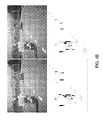
- FIG. 4D is another image output of an obstacle in a multiple-vehicles state.
- relative distances of the obstacles can respectively indicated to the multiple obstacles.
- FIG. 4E is still another image of an obstacle in a night state. We can see from the figure that even if it is under a night dim light condition, the apparatus for detecting an obstacle through stereovision can still detect a relative distance of the preceding obstacle and directly indicate the relative distance of the obstacle in the image.
- FIG. 5 is a flow chart of a method for detecting an obstacle through stereovision of the present invention, the method comprises the following steps:
- Step S 10 capturing a plurality of images through a plurality of cameras; capturing images with the plurality of cameras can generate stereovision to conquer effectively drawbacks of using only one single camera.
- Step S 20 edge-detecting the image to generate a plurality of edge objects and object information corresponding to each edge object.
- the step further comprises the following step: using a decimation manner to lower the resolution of the image.
- the calculation amount of the follow-up processes of the image can substantially be lowered to allow relative information (distance, shape and etc) can be calculated in a real-time mode when a car is practically driven on the road and proper warning information can further be provided for a driver immediately.
- step S 20 may further comprises the following step: eliminating noise of the image by means of low-pass filtering wave.
- horizontal edge detection and vertical edge detection it comprises the following steps: using an edge detection operator to detect the image to generate horizontal line segments in the horizontal edge detection and connecting the horizontal line segments to form a horizontal bounding box; using an edge detection operator to detect the image to generate vertical line segments in the vertical edge detection and connecting the vertical line segments to form a vertical bounding box.
- Step S 30 matching a focus (f) and a horizontal spacing interval (B) of two cameras in the plurality of cameras according to the object information to generate a relative object distance corresponding to each edge object.
- the step may further comprise the following steps: comparing the object information to generate a suspect object and searching the image according to the suspect to generate a disparity value (dx) of the edge object. Therefore, a relative distance (Z) can be obtained by means of
- Step S 40 comparing the relative object distance with a threshold distance.
- Step S 50 grouping the edge objects with the relative object distance smaller than the threshold distance to form an obstacle and obtaining a relative obstacle distance corresponding to the obstacle.
- step 50 may further comprise the following steps: displaying the image and indicating the relative distance of the obstacle so that the driver is allowed to discern clearly what distance is away from the preceding obstacle; otherwise, setting a warning distance, comparing the warning distance with the relative obstacle distance, generating warning information so that it can prevent a driver from dozing off. That is to say, an alarm sound is emitted to notice a driver before colliding with a preceding obstacle.
Abstract
Description
B=D×L+DxR (2)
Substitute formula (1) into formula (2), we can obtain:
Therefore, from formula (3) we can obtain a relative distance Z between the object O and the cameras, and it is:
Claims (20)
Applications Claiming Priority (3)
| Application Number | Priority Date | Filing Date | Title |
|---|---|---|---|
| TW96117494A | 2007-05-16 | ||
| TW096117494 | 2007-05-16 | ||
| TW096117494A TWI327536B (en) | 2007-05-16 | 2007-05-16 | Device and method for detecting obstacle by stereo computer vision |
Publications (2)
| Publication Number | Publication Date |
|---|---|
| US20080285799A1 US20080285799A1 (en) | 2008-11-20 |
| US8041079B2 true US8041079B2 (en) | 2011-10-18 |
Family
ID=40027507
Family Applications (1)
| Application Number | Title | Priority Date | Filing Date |
|---|---|---|---|
| US12/023,700 Active 2030-08-19 US8041079B2 (en) | 2007-05-16 | 2008-01-31 | Apparatus and method for detecting obstacle through stereovision |
Country Status (2)
| Country | Link |
|---|---|
| US (1) | US8041079B2 (en) |
| TW (1) | TWI327536B (en) |
Cited By (14)
| Publication number | Priority date | Publication date | Assignee | Title |
|---|---|---|---|---|
| US20120027258A1 (en) * | 2009-04-23 | 2012-02-02 | Naohide Uchida | Object detection device |
| US20130253796A1 (en) * | 2012-03-26 | 2013-09-26 | Robert Bosch Gmbh | Multi-surface model-based tracking |
| CN109300145A (en) * | 2018-08-20 | 2019-02-01 | 彭楷文 | NEW ADAPTIVE intelligence dazzle system |
| US10209718B2 (en) | 2017-03-14 | 2019-02-19 | Starsky Robotics, Inc. | Vehicle sensor system and method of use |
| US20190122173A1 (en) * | 2017-10-20 | 2019-04-25 | BXB Digital Pty Limited | Systems and methods for tracking goods carriers |
| US10657393B2 (en) * | 2017-09-20 | 2020-05-19 | Aptiv Technologies Limited | Device and a method for distinguishing between traversable and nontraversable objects |
| US10932635B2 (en) | 2015-10-14 | 2021-03-02 | Toshiba Lifestyle Products & Services Corporation | Vacuum cleaner |
| US10977460B2 (en) | 2017-08-21 | 2021-04-13 | BXB Digital Pty Limited | Systems and methods for pallet tracking using hub and spoke architecture |
| US11062256B2 (en) | 2019-02-25 | 2021-07-13 | BXB Digital Pty Limited | Smart physical closure in supply chain |
| US11244378B2 (en) | 2017-04-07 | 2022-02-08 | BXB Digital Pty Limited | Systems and methods for tracking promotions |
| US11249169B2 (en) | 2018-12-27 | 2022-02-15 | Chep Technology Pty Limited | Site matching for asset tracking |
| US11507771B2 (en) | 2017-05-02 | 2022-11-22 | BXB Digital Pty Limited | Systems and methods for pallet identification |
| US11663549B2 (en) | 2017-05-02 | 2023-05-30 | BXB Digital Pty Limited | Systems and methods for facility matching and localization |
| US11900307B2 (en) | 2017-05-05 | 2024-02-13 | BXB Digital Pty Limited | Placement of tracking devices on pallets |
Families Citing this family (19)
| Publication number | Priority date | Publication date | Assignee | Title |
|---|---|---|---|---|
| DE102009006125A1 (en) * | 2009-01-26 | 2009-09-10 | Daimler Ag | Method for determining correspondence of image points in stereoscopically captured images, involves filtering horizontal edges from stereoscopically captured images by horizontal edge filter during image pre-processing |
| CN102375985A (en) * | 2010-08-10 | 2012-03-14 | 富士通株式会社 | Target detection method and device |
| US10134150B2 (en) * | 2010-08-10 | 2018-11-20 | Monotype Imaging Inc. | Displaying graphics in multi-view scenes |
| JP5459154B2 (en) * | 2010-09-15 | 2014-04-02 | トヨタ自動車株式会社 | Vehicle surrounding image display apparatus and method |
| CN102303563B (en) * | 2011-06-16 | 2014-03-26 | 广东铁将军防盗设备有限公司 | System and method for prewarning front vehicle collision |
| US8803800B2 (en) * | 2011-12-02 | 2014-08-12 | Microsoft Corporation | User interface control based on head orientation |
| US8736463B1 (en) * | 2012-01-30 | 2014-05-27 | Google Inc. | Object bounding box estimation |
| US20140198977A1 (en) * | 2012-03-21 | 2014-07-17 | Texas Instruments Incorporated | Enhancement of Stereo Depth Maps |
| JP2013200603A (en) * | 2012-03-23 | 2013-10-03 | Hitachi Automotive Systems Ltd | In-vehicle image processing device and method |
| TW201351301A (en) | 2012-06-08 | 2013-12-16 | Automotive Res & Testing Ct | Self-adaptive obstacle image detection method |
| US9894269B2 (en) * | 2012-10-31 | 2018-02-13 | Atheer, Inc. | Method and apparatus for background subtraction using focus differences |
| US9131118B2 (en) * | 2012-11-14 | 2015-09-08 | Massachusetts Institute Of Technology | Laser speckle photography for surface tampering detection |
| US9523984B1 (en) * | 2013-07-12 | 2016-12-20 | Google Inc. | Methods and systems for determining instructions for pulling over an autonomous vehicle |
| JP2015047298A (en) * | 2013-08-30 | 2015-03-16 | 船井電機株式会社 | Walking assist moving body |
| TWI595457B (en) * | 2014-12-02 | 2017-08-11 | Metal Ind Res And Dev Centre | Anti-collision three-dimensional depth sensing system and its operation method |
| EP3279830B1 (en) * | 2016-08-02 | 2020-10-28 | Veoneer Sweden AB | A vision system and method for a motor vehicle |
| CN108583571A (en) * | 2018-04-28 | 2018-09-28 | 深圳市商汤科技有限公司 | Collision control method and device, electronic equipment and storage medium |
| CN109163707B (en) * | 2018-09-06 | 2019-11-26 | 百度在线网络技术(北京)有限公司 | Method for barrier perception, system, computer equipment, computer storage medium |
| US10793150B2 (en) * | 2018-09-14 | 2020-10-06 | Wipro Limited | Method and device for controlling vehicle based on neighboring vehicles |
Citations (11)
| Publication number | Priority date | Publication date | Assignee | Title |
|---|---|---|---|---|
| WO1997018523A2 (en) | 1995-11-14 | 1997-05-22 | Moshe Razon | Computer stereo vision system and method |
| TW406009B (en) | 1999-07-16 | 2000-09-21 | Nat Science Council | 3-D localization method of clustered microcalcifications using cranio-caudal and medio-lateral oblique views |
| US6263088B1 (en) * | 1997-06-19 | 2001-07-17 | Ncr Corporation | System and method for tracking movement of objects in a scene |
| US20030095133A1 (en) | 2001-11-20 | 2003-05-22 | Yung-Feng Chiu | System and method for full-scene anti-aliasing and stereo three-dimensional display control |
| US20040234136A1 (en) * | 2003-03-24 | 2004-11-25 | Ying Zhu | System and method for vehicle detection and tracking |
| US20060013439A1 (en) | 2001-05-23 | 2006-01-19 | Kabushiki Kaisha Toshiba | System and method for detecting obstacle |
| TW200604959A (en) | 2004-07-30 | 2006-02-01 | Jia-Bin Wang | 3D space simulation action detection system |
| US20060182312A1 (en) | 2002-03-29 | 2006-08-17 | Kabushiki Kaisha Toshiba | Obstacle detecting apparatus and method |
| US20060197019A1 (en) | 2004-07-07 | 2006-09-07 | Nissan Motor Co., Ltd. | Object detection apparatus, especially for vehicles |
| US20080273751A1 (en) * | 2006-10-16 | 2008-11-06 | Chang Yuan | Detection and Tracking of Moving Objects from a Moving Platform in Presence of Strong Parallax |
| US20110025548A1 (en) * | 2009-07-31 | 2011-02-03 | Gm Global Technology Operations, Inc. | System and method for vehicle sensor fusion |
-
2007
- 2007-05-16 TW TW096117494A patent/TWI327536B/en not_active IP Right Cessation
-
2008
- 2008-01-31 US US12/023,700 patent/US8041079B2/en active Active
Patent Citations (12)
| Publication number | Priority date | Publication date | Assignee | Title |
|---|---|---|---|---|
| WO1997018523A2 (en) | 1995-11-14 | 1997-05-22 | Moshe Razon | Computer stereo vision system and method |
| US6263088B1 (en) * | 1997-06-19 | 2001-07-17 | Ncr Corporation | System and method for tracking movement of objects in a scene |
| TW406009B (en) | 1999-07-16 | 2000-09-21 | Nat Science Council | 3-D localization method of clustered microcalcifications using cranio-caudal and medio-lateral oblique views |
| US20060013439A1 (en) | 2001-05-23 | 2006-01-19 | Kabushiki Kaisha Toshiba | System and method for detecting obstacle |
| US20030095133A1 (en) | 2001-11-20 | 2003-05-22 | Yung-Feng Chiu | System and method for full-scene anti-aliasing and stereo three-dimensional display control |
| US20060182312A1 (en) | 2002-03-29 | 2006-08-17 | Kabushiki Kaisha Toshiba | Obstacle detecting apparatus and method |
| US20040234136A1 (en) * | 2003-03-24 | 2004-11-25 | Ying Zhu | System and method for vehicle detection and tracking |
| US7764808B2 (en) * | 2003-03-24 | 2010-07-27 | Siemens Corporation | System and method for vehicle detection and tracking |
| US20060197019A1 (en) | 2004-07-07 | 2006-09-07 | Nissan Motor Co., Ltd. | Object detection apparatus, especially for vehicles |
| TW200604959A (en) | 2004-07-30 | 2006-02-01 | Jia-Bin Wang | 3D space simulation action detection system |
| US20080273751A1 (en) * | 2006-10-16 | 2008-11-06 | Chang Yuan | Detection and Tracking of Moving Objects from a Moving Platform in Presence of Strong Parallax |
| US20110025548A1 (en) * | 2009-07-31 | 2011-02-03 | Gm Global Technology Operations, Inc. | System and method for vehicle sensor fusion |
Cited By (19)
| Publication number | Priority date | Publication date | Assignee | Title |
|---|---|---|---|---|
| US9053554B2 (en) * | 2009-04-23 | 2015-06-09 | Toyota Jidosha Kabushiki Kaisha | Object detection device using an image captured with an imaging unit carried on a movable body |
| US20120027258A1 (en) * | 2009-04-23 | 2012-02-02 | Naohide Uchida | Object detection device |
| US20130253796A1 (en) * | 2012-03-26 | 2013-09-26 | Robert Bosch Gmbh | Multi-surface model-based tracking |
| US9466215B2 (en) * | 2012-03-26 | 2016-10-11 | Robert Bosch Gmbh | Multi-surface model-based tracking |
| US10932635B2 (en) | 2015-10-14 | 2021-03-02 | Toshiba Lifestyle Products & Services Corporation | Vacuum cleaner |
| US11073836B2 (en) | 2017-03-14 | 2021-07-27 | Gatik Ai Inc. | Vehicle sensor system and method of use |
| US10209718B2 (en) | 2017-03-14 | 2019-02-19 | Starsky Robotics, Inc. | Vehicle sensor system and method of use |
| US11681299B2 (en) | 2017-03-14 | 2023-06-20 | Gatik Ai Inc. | Vehicle sensor system and method of use |
| US11244378B2 (en) | 2017-04-07 | 2022-02-08 | BXB Digital Pty Limited | Systems and methods for tracking promotions |
| US11507771B2 (en) | 2017-05-02 | 2022-11-22 | BXB Digital Pty Limited | Systems and methods for pallet identification |
| US11663549B2 (en) | 2017-05-02 | 2023-05-30 | BXB Digital Pty Limited | Systems and methods for facility matching and localization |
| US11900307B2 (en) | 2017-05-05 | 2024-02-13 | BXB Digital Pty Limited | Placement of tracking devices on pallets |
| US10977460B2 (en) | 2017-08-21 | 2021-04-13 | BXB Digital Pty Limited | Systems and methods for pallet tracking using hub and spoke architecture |
| US10657393B2 (en) * | 2017-09-20 | 2020-05-19 | Aptiv Technologies Limited | Device and a method for distinguishing between traversable and nontraversable objects |
| US10956854B2 (en) * | 2017-10-20 | 2021-03-23 | BXB Digital Pty Limited | Systems and methods for tracking goods carriers |
| US20190122173A1 (en) * | 2017-10-20 | 2019-04-25 | BXB Digital Pty Limited | Systems and methods for tracking goods carriers |
| CN109300145A (en) * | 2018-08-20 | 2019-02-01 | 彭楷文 | NEW ADAPTIVE intelligence dazzle system |
| US11249169B2 (en) | 2018-12-27 | 2022-02-15 | Chep Technology Pty Limited | Site matching for asset tracking |
| US11062256B2 (en) | 2019-02-25 | 2021-07-13 | BXB Digital Pty Limited | Smart physical closure in supply chain |
Also Published As
| Publication number | Publication date |
|---|---|
| TWI327536B (en) | 2010-07-21 |
| US20080285799A1 (en) | 2008-11-20 |
| TW200846218A (en) | 2008-12-01 |
Similar Documents
| Publication | Publication Date | Title |
|---|---|---|
| US8041079B2 (en) | Apparatus and method for detecting obstacle through stereovision | |
| US11183067B2 (en) | Image generating apparatus, image generating method, and recording medium | |
| EP2924653B1 (en) | Image processing apparatus and image processing method | |
| US7366325B2 (en) | Moving object detection using low illumination depth capable computer vision | |
| US9813593B2 (en) | Outside recognition apparatus and lens dirtiness detection method | |
| US8244027B2 (en) | Vehicle environment recognition system | |
| CN112349144B (en) | Monocular vision-based vehicle collision early warning method and system | |
| CN107891808B (en) | Driving reminding method and device and vehicle | |
| US20140071240A1 (en) | Free space detection system and method for a vehicle using stereo vision | |
| EP2928178B1 (en) | On-board control device | |
| CN110909705B (en) | Road side parking space sensing method and system based on vehicle-mounted camera | |
| CN101633356A (en) | System and method for detecting pedestrians | |
| Lin et al. | Lane departure and front collision warning using a single camera | |
| CN110135235B (en) | Glare processing method and device and vehicle | |
| EP2741234B1 (en) | Object localization using vertical symmetry | |
| KR101239718B1 (en) | System and method for detecting object of vehicle surroundings | |
| CN111967396A (en) | Processing method, device and equipment for obstacle detection and storage medium | |
| CN113569812A (en) | Unknown obstacle identification method and device and electronic equipment | |
| Yang | Estimation of vehicle's lateral position via the Lucas-Kanade optical flow method | |
| JP2014016981A (en) | Movement surface recognition device, movement surface recognition method, and movement surface recognition program | |
| US20230098440A1 (en) | Imaging device, imaging system, and imaging method | |
| CN110765877B (en) | Pedestrian detection method and system based on thermal imager and binocular camera | |
| JP5957182B2 (en) | Road surface pattern recognition method and vehicle information recording apparatus | |
| JP2006317193A (en) | Image processing apparatus, imaging processing method and program for processing image | |
| TW202241739A (en) | Method and system for identifying a parking space |
Legal Events
| Date | Code | Title | Description |
|---|---|---|---|
| AS | Assignment |
Owner name: INSTITUTE OF TECHNOLOGY, NATIONAL DEFENSE UNIVERSI Free format text: ASSIGNMENT OF ASSIGNORS INTEREST;ASSIGNORS:CHIU, CHUNG-CHENG;CHUNG, MENG-LIANG;CHEN, WEN-CHUNG;AND OTHERS;REEL/FRAME:020450/0674 Effective date: 20080129 |
|
| STCF | Information on status: patent grant |
Free format text: PATENTED CASE |
|
| FPAY | Fee payment |
Year of fee payment: 4 |
|
| MAFP | Maintenance fee payment |
Free format text: PAYMENT OF MAINTENANCE FEE, 8TH YR, SMALL ENTITY (ORIGINAL EVENT CODE: M2552); ENTITY STATUS OF PATENT OWNER: SMALL ENTITY Year of fee payment: 8 |
|
| MAFP | Maintenance fee payment |
Free format text: PAYMENT OF MAINTENANCE FEE, 12TH YR, SMALL ENTITY (ORIGINAL EVENT CODE: M2553); ENTITY STATUS OF PATENT OWNER: SMALL ENTITY Year of fee payment: 12 |