US8042684B2 - Receiving element for a dental implant - Google Patents

Receiving element for a dental implant Download PDF

Info

Publication number
US8042684B2
US8042684B2 US12/602,687 US60268708A US8042684B2 US 8042684 B2 US8042684 B2 US 8042684B2 US 60268708 A US60268708 A US 60268708A US 8042684 B2 US8042684 B2 US 8042684B2
Authority
US
United States
Prior art keywords
receiving element
plate
dental implant
center axis
implant according
Prior art date
Legal status (The legal status is an assumption and is not a legal conclusion. Google has not performed a legal analysis and makes no representation as to the accuracy of the status listed.)
Active
Application number
US12/602,687
Other versions
US20100173261A1 (en
Inventor
Daniel Guenter
Rainer Bammerlin
Current Assignee (The listed assignees may be inaccurate. Google has not performed a legal analysis and makes no representation or warranty as to the accuracy of the list.)
Straumann Holding AG
Original Assignee
Straumann Holding AG
Priority date (The priority date is an assumption and is not a legal conclusion. Google has not performed a legal analysis and makes no representation as to the accuracy of the date listed.)
Filing date
Publication date
Application filed by Straumann Holding AG filed Critical Straumann Holding AG
Assigned to STRAUMANN HOLDING AG reassignment STRAUMANN HOLDING AG ASSIGNMENT OF ASSIGNORS INTEREST (SEE DOCUMENT FOR DETAILS). Assignors: BAMMERLIN, RAINER, GUENTER, DANIEL
Publication of US20100173261A1 publication Critical patent/US20100173261A1/en
Application granted granted Critical
Publication of US8042684B2 publication Critical patent/US8042684B2/en
Active legal-status Critical Current
Anticipated expiration legal-status Critical

Links

Images

Classifications

    • AHUMAN NECESSITIES
    • A61MEDICAL OR VETERINARY SCIENCE; HYGIENE
    • A61CDENTISTRY; APPARATUS OR METHODS FOR ORAL OR DENTAL HYGIENE
    • A61C8/00Means to be fixed to the jaw-bone for consolidating natural teeth or for fixing dental prostheses thereon; Dental implants; Implanting tools
    • A61C8/0087Means for sterile storage or manipulation of dental implants
    • AHUMAN NECESSITIES
    • A61MEDICAL OR VETERINARY SCIENCE; HYGIENE
    • A61CDENTISTRY; APPARATUS OR METHODS FOR ORAL OR DENTAL HYGIENE
    • A61C19/00Dental auxiliary appliances
    • A61C19/02Protective casings, e.g. boxes for instruments; Bags
    • AHUMAN NECESSITIES
    • A61MEDICAL OR VETERINARY SCIENCE; HYGIENE
    • A61CDENTISTRY; APPARATUS OR METHODS FOR ORAL OR DENTAL HYGIENE
    • A61C8/00Means to be fixed to the jaw-bone for consolidating natural teeth or for fixing dental prostheses thereon; Dental implants; Implanting tools

Definitions

  • the present invention relates to a receiving element for an implant, in particular for screw- or cylinder-shaped implants.
  • Such implants are already known e.g. from dental technology and are substantially similar to a screw, the apical area of the screw being inserted in a bone and the coronal area being suitable to receive a dental prosthesis.
  • different embodiments of holding elements fastened to the implant which, on the one hand, fix the implant into place and, on the other hand, allow sterile removal from the receiving element.
  • they also ensure that from manufacturing until surgical intervention, an implant does not come in contact with non-sterile means, such as hands.
  • the relevant area of application for the invention is where the implants, e.g. for reasons of necessary sterile handling, may at least not directly be touched with one's hands, and where secure grasping of the implants is required.
  • receiving elements The function of such receiving elements is to transport the implant safely and provide a sterile environment for storage.
  • the implant is taken from the receiving element which generally has a holding element fastened to the implant (in the following, the combination of implant and holding element attached to it will be called implant assembly for simplification), e.g. by means of a tool applied to the implant, and the implant is subsequently placed on the prepared implant site of the patient and the holding element is removed.
  • implant assembly for simplification
  • a cylindrical ampule to be inserted in an outer capsule which ampule is suitable for receiving an implant.
  • the ampule has a face region provided with an recess which is laterally open. This recess is used to insert an implant assembly consisting of the implant and a holding element additionally connected to the implant.
  • the implant assembly is fixed into place in a throat of the ampule by being pressed through an opening.
  • substantial pressure must be applied when the implant is pressed in; with a rigid structure of an ampule and a receiving element, the consequence is that the construction material is subjected to substantial stress, since the forces that occur spread both along the expansion groove and along the cylinder surface.
  • the face side of the ampule has a relatively small cross-section, and the entire holding force between an implant and the interior of the throat is limited to this narrow area, the holding force or withdrawal force, respectively, being consequently increased by the pressure or compression, respectively, when the implant is removed from the holder. This increases the grip on the implant, making the removal process difficult to control.
  • the cylindrical ampule can move about its axis within a certain range, which makes it difficult to grip.
  • the object of the present invention is to provide a receiving element for a dental implant which fixes a dental implant assembly in place more secure and which can better convert and carry off the forces occurring when the dental implant assembly is placed on the structure of the receiving element. Furthermore, simpler and safer handling should be provided and economical manufacturing with existing techniques should be possible.
  • the object of the present invention is to provide a receiving element for a dental implant having improved stability and conversion of forces and which avoids the drawbacks mentioned above.
  • another object of the present invention is to provide a receiving element for a dental implant which is better protected against slipping on a surface.
  • Another object of the present invention is that the receiving element can be handled more easily and more safely.
  • Another object of the present invention is that the receiving element can be manufactured easily and inexpensively with well-known methods.
  • the constructive characteristics of a substantially cylindrical receiving element according to the present invention consist in that the head area holding the receiving element is nearly uncoupled from the body so that forces occurring during removal of the dental implant from the holder through the aperture provided for this purpose are effectively diverted and/or completely eliminated.
  • the substantially square body portion is advantageously provided with an open side for easy insertion of the dental implant.
  • the head area has a first surface suitable for clamping connection with a dental implant and a second surface which prevents the dental implant from touching the interior wall of the body part.
  • one side of the receiving element is provided with a plane surface ensuring stable positioning on a surface such as the operating table.
  • the receiving element has a plurality of reinforcing ribs in its body area which, on the one hand, reinforce the outer wall and, on the other hand, ensure a better grip.
  • FIG. 1 shows a side view of a receiving element for a dental implant according to an embodiment of the invention
  • FIG. 2 shows a front view of a receiving element for a dental implant according to FIG. 1 ;
  • FIG. 3 shows a longitudinal section of a receiving element for a dental implant according to FIG. 1 , taken along line A-A in the direction of the arrow;
  • FIG. 4 shows a longitudinal section of a receiving element for a dental implant according to FIG. 1 , taken along line B-B in the direction of the arrow;
  • FIG. 5 shows a sectional view of a receiving element for a dental implant according to FIG. 1 , taken along line F-F in the direction of the arrow;
  • FIG. 6 shows a sectional view of a receiving element for a dental implant according to FIG. 1 , taken along line D-D in the direction of the arrow;
  • FIG. 7 shows a top view of a receiving element for a dental implant according to FIG. 1 .
  • a currently preferred embodiment of the present invention of a receiving element for a dental implant is described, which element consists of a substantially cylindrical bottom area, a body area enclosing the dental implant and a flexible head area formed by two plates, the head area being provided with a clamping device for receiving a dental implant, which device is suitable for releasably clamping and fixing a dental implant into place.
  • FIG. 1 shows a receiving element 1 for a dental implant, the receiving element 1 basically having three portions.
  • a first portion forming the head area consists of an approximately C-shaped, plane front face 2 comprising a first plate 3 which is suitable for fixing a dental implant (not shown) into place, as is described further in the foregoing.
  • the first plate 3 is adjacent to an open area 5 surrounded by a first shoulder 4 bordering on the first plate 3 and a second shoulder 4 ′ below it which borders on a second plate 6 .
  • the open area 5 which is preferably jaw-shaped preferably extends from its open side at a respective end of the plates 3 , 6 to a theoretical center axis Z of the receiving element 1 , the opening width in the area of the center axis Z being advantageously smaller than on the outer side.
  • the jaw-like area 5 achieves a mechanical uncoupling of the plates 3 , 6 and of the first plate 3 from the body 7 , respectively.
  • a chamfer 17 from an outer edge of the plane front face 2 to a plane head area 16 is provided, the plane head area 16 bordering on a plane head edge 15 which borders both on the head area 16 and on a body 7 of the receiving element 1 .
  • Part of the second plate 6 which borders on the jaw-like open area 5 and on the second shoulder 4 ′, respectively, is substantially plane.
  • the part of the second plate 6 which is below the jaw-like area 5 then borders on a second portion formed by the body 7 and provided with a plurality of symmetrically arranged reinforcing ribs 8 .
  • these reinforcing ribs 8 have a longitudinal shape.
  • a base surface 9 borders on the edge of the body 7 opposite to the second plate 6 , which base surface is substantially symmetrically round and on which the body 7 is arranged perpendicularly.
  • the third portion comprises a perimetric surrounding edge 10 embedded between the base surface 9 and a bottom part 11 , with the bottom part 11 transitioning on one side into the standing area 12 which is suitable for the placement on a surface.
  • a bottom portion 13 formed between the bottom edge 14 and the standing area 12 is preferably plane.
  • the bottom edge 14 which is also plane borders on the bottom portion 13 . Due to the plane embodiment of the head edge 15 and of the bottom edge 14 , it is possible to position the receiving element 1 stably on a surface and to both prevent it from rolling away and to grip it easily.
  • FIG. 2 shows further features of the receiving element 1 , a first through hole 23 and a second through hole 24 being arranged in the center of the first plate 3 .
  • the second through hole 24 can preferably have a smaller diameter than the first through hole 23 , although in the presently preferred embodiment the difference in diameter is not indispensable.
  • the first through hole 23 and the second through hole 24 are, in one place, connected to each other by an open groove 39 as is also shown in FIG. 7 .
  • the first through hole 23 borders on an opening 40 , see FIG. 7 , of the first plate 3 .
  • a first elongated hole 18 and a second elongated hole 19 are provided in the body 7 as can be seen in FIG. 2 .
  • FIG. 3 and FIG. 4 show additional features of the receiving element 1 , a portion of the first plate 3 being provided with a chamfered leg 22 which extends from the outer edge approximately up to the area of a theoretical center axis Z of the receiving element 1 , the chamfered leg 22 allowing an easy insertion of a dental implant.
  • the first plate 3 can be elastically deformed with respect to the second plate 6 in a direction perpendicular to the center axis Z of the receiving element 1 until the dental implant is locked into place in the first through hole 23 and held there clampingly, a first gap 36 and a second gap 37 of the jaw-like portion 5 mechanically uncoupling the first plate 3 from the body 7 and from the second plate 6 , respectively, as mentioned above.
  • the chamfer 17 on the opposite side advantageously has a resilient effect.
  • a first reinforcement 20 and a second reinforcement 21 are used to strengthen the construction against the tensions produced when the dental implant is pressed in.
  • a first notch 34 and a second notch 35 which can have a conical shape and which are arranged symmetrically in the first plate 3 and adjacent to the first through hole 23 and the second through hole 24 are suitable for distributing the forces when the dental implant is pressed in through the opening 40 of the first plate 3 , and the first plate 3 can be expanded elastically in a direction perpendicular to the center axis Z.
  • the conical shape of the notches is preferred especially for machining reasons if the receiving element is manufactured by injection molding.
  • the second through hole 24 has a smaller diameter than the first through hole 23 and is connected to it by the groove 39 so that the through hole 24 is used as an expansion through hole and can be enlarged when a dental implant is pressed in.
  • the elastic deformability of the first plate 3 advantageously results both in a clamping and in a snap-in connection which securely fixes the dental implant in the first through hole 23 .
  • FIG. 5 and FIG. 6 show the head area of the receiving element 1 , FIG. 5 showing an area 41 which has, in the portion of the opening 40 , see FIG. 7 , a first chamfer 26 and a second chamfer 27 used for easy insertion of the dental implant.
  • the angle between the first and the second chamfer is preferably within a range of 80 to 120 degrees.
  • the area 41 which is enclosed over the entire cross-section up to the chamfers 26 , 27 is rigid so as to form the U-shaped portion 32 shown in FIG. 6 .
  • the inner surface of the U-shaped portion 32 forms a stopping portion 33 in which an inserted dental implant is kept in a stable position so that contact with the interior walls of the body 7 , e. g. during transport, is excluded.
  • the base surface 9 from FIG. 1 has an annular portion 25 having approximately the width of the U-shaped portion 32 and, in its center, the base surface has a third through hole 42 with a larger diameter than the first and the second through hole 23 , 24 .
  • FIG. 7 shows that the first through hole 23 is aligned with the third through hole 42 .
  • the first notch 34 and the second notch 35 extend substantially parallel thereto, slightly curving in the direction of the center of the second through hole 24 near the first 23 and the second 24 through hole.
  • the receiving element 1 can be manufactured with conventional processes, e. g. casting, and is preferably made of an elastic plastic material.

Landscapes

  • Health & Medical Sciences (AREA)
  • Oral & Maxillofacial Surgery (AREA)
  • Dentistry (AREA)
  • Epidemiology (AREA)
  • Life Sciences & Earth Sciences (AREA)
  • Animal Behavior & Ethology (AREA)
  • General Health & Medical Sciences (AREA)
  • Public Health (AREA)
  • Veterinary Medicine (AREA)
  • Orthopedic Medicine & Surgery (AREA)
  • Dental Prosthetics (AREA)

Abstract

A receiving element for a dental implant is provided. The receiving element has a hollow body extending along a center axis of the receiving element, and a first plate and a second plate extending substantially perpendicular to the center axis of the receiving element and configured to fix a dental implant releasably in a stable position. The first plate and the second plate each has a front end, a rear end opposite to the front end, a first lateral end and a second lateral end opposite to the first lateral end. The receiving element further has an open portion disposed between the first plate and the second plate to partially separate the first plate and the second plate. The open portion extends from the front end substantially up to the center axis of the receiving element. The open portion has a first gap extending from the first lateral end substantially up to the center axis and a second gap extending from the second lateral end substantially up to the center axis, each gap allowing communication along the entire length thereof between an interior of the body and an exterior of the body.

Description

FIELD OF USE OF THE INVENTION
The present invention relates to a receiving element for an implant, in particular for screw- or cylinder-shaped implants.
Such implants are already known e.g. from dental technology and are substantially similar to a screw, the apical area of the screw being inserted in a bone and the coronal area being suitable to receive a dental prosthesis. In addition, in dental surgery, different embodiments of holding elements fastened to the implant are known which, on the one hand, fix the implant into place and, on the other hand, allow sterile removal from the receiving element. In addition, they also ensure that from manufacturing until surgical intervention, an implant does not come in contact with non-sterile means, such as hands. The relevant area of application for the invention is where the implants, e.g. for reasons of necessary sterile handling, may at least not directly be touched with one's hands, and where secure grasping of the implants is required.
The function of such receiving elements is to transport the implant safely and provide a sterile environment for storage. To remove the implant during a surgical intervention performed under sterile conditions, the implant is taken from the receiving element which generally has a holding element fastened to the implant (in the following, the combination of implant and holding element attached to it will be called implant assembly for simplification), e.g. by means of a tool applied to the implant, and the implant is subsequently placed on the prepared implant site of the patient and the holding element is removed. For further protection, it is also common to store the receiving element in a secondary protection element until the time of implanting.
PRIOR ART
From WO98/55039, a cylindrical ampule to be inserted in an outer capsule is known, which ampule is suitable for receiving an implant. The ampule has a face region provided with an recess which is laterally open. This recess is used to insert an implant assembly consisting of the implant and a holding element additionally connected to the implant. The implant assembly is fixed into place in a throat of the ampule by being pressed through an opening. To achieve sufficient fixation, substantial pressure must be applied when the implant is pressed in; with a rigid structure of an ampule and a receiving element, the consequence is that the construction material is subjected to substantial stress, since the forces that occur spread both along the expansion groove and along the cylinder surface. There is a danger of cracks formation on the face side in case of pressure which is too strong, which cracks can reduce or even offset the clamping effect within the throat. Furthermore, due to the rigid construction, insertion is only possible by using great force if the recess has only a small aperture angle, since expansion can only take place within the area of the expansion groove, which is relatively narrow, and the cylinder surface further impedes expansion. An enlargement of the aperture angle of the recess facilitates insertion of the dental implant, however at the cost of a good clamping behavior, so that the implant can easily slide out of the recess and touch non-sterile surfaces. Even worse, the implant can also be damaged if, for instance, it falls down from the operating table to the floor. Also, the face side of the ampule has a relatively small cross-section, and the entire holding force between an implant and the interior of the throat is limited to this narrow area, the holding force or withdrawal force, respectively, being consequently increased by the pressure or compression, respectively, when the implant is removed from the holder. This increases the grip on the implant, making the removal process difficult to control.
In addition, storage over a longer time can lead to a weakening at the clamping area which, in the worst case, can cause the implant to be no longer held with full clamping force, making it oscillate within the ampule so that it can be damaged by contact with the ampule.
Furthermore, if deposited, the cylindrical ampule can move about its axis within a certain range, which makes it difficult to grip.
SUMMARY OF THE INVENTION
In view of the above-mentioned drawbacks of the prior art devices for receiving a dental implant, the object of the present invention is to provide a receiving element for a dental implant which fixes a dental implant assembly in place more secure and which can better convert and carry off the forces occurring when the dental implant assembly is placed on the structure of the receiving element. Furthermore, simpler and safer handling should be provided and economical manufacturing with existing techniques should be possible.
The object of the present invention is to provide a receiving element for a dental implant having improved stability and conversion of forces and which avoids the drawbacks mentioned above.
Within this aim, another object of the present invention is to provide a receiving element for a dental implant which is better protected against slipping on a surface.
Another object of the present invention is that the receiving element can be handled more easily and more safely.
Another object of the present invention is that the receiving element can be manufactured easily and inexpensively with well-known methods.
This aim and these and other objects to be found in the following specification are fulfilled by a receiving element for a dental implant according to Claim 1. Other advantageous embodiments of the present invention are the subject matter of the dependent claims.
The constructive characteristics of a substantially cylindrical receiving element according to the present invention consist in that the head area holding the receiving element is nearly uncoupled from the body so that forces occurring during removal of the dental implant from the holder through the aperture provided for this purpose are effectively diverted and/or completely eliminated. The substantially square body portion is advantageously provided with an open side for easy insertion of the dental implant. Furthermore, the head area has a first surface suitable for clamping connection with a dental implant and a second surface which prevents the dental implant from touching the interior wall of the body part.
Furthermore, one side of the receiving element is provided with a plane surface ensuring stable positioning on a surface such as the operating table. In a preferred embodiment, the receiving element has a plurality of reinforcing ribs in its body area which, on the one hand, reinforce the outer wall and, on the other hand, ensure a better grip.
SHORT DESCRIPTION OF THE FIGURES
Further features and advantages of the present invention as well as the operating method of the exemplary embodiments of the present invention are described below with reference to the accompanying drawings.
The accompanying drawings illustrate the present invention and, together with the specification, are used to explain the basics of the invention and to enable a person skilled in the relevant art to manufacture and use the invention. For better comprehensibility, identical elements are for the most part not designated in the following figures as long as they can be clearly recognized as “repeated elements”.
Therein:
FIG. 1 shows a side view of a receiving element for a dental implant according to an embodiment of the invention;
FIG. 2 shows a front view of a receiving element for a dental implant according to FIG. 1;
FIG. 3 shows a longitudinal section of a receiving element for a dental implant according to FIG. 1, taken along line A-A in the direction of the arrow;
FIG. 4 shows a longitudinal section of a receiving element for a dental implant according to FIG. 1, taken along line B-B in the direction of the arrow;
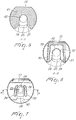
FIG. 5 shows a sectional view of a receiving element for a dental implant according to FIG. 1, taken along line F-F in the direction of the arrow;
FIG. 6 shows a sectional view of a receiving element for a dental implant according to FIG. 1, taken along line D-D in the direction of the arrow;
FIG. 7 shows a top view of a receiving element for a dental implant according to FIG. 1.
DESCRIPTION OF PREFERRED EMBODIMENTS OF THE INVENTION
Based on FIG. 1 to FIG. 7, a currently preferred embodiment of the present invention of a receiving element for a dental implant is described, which element consists of a substantially cylindrical bottom area, a body area enclosing the dental implant and a flexible head area formed by two plates, the head area being provided with a clamping device for receiving a dental implant, which device is suitable for releasably clamping and fixing a dental implant into place.
FIG. 1 shows a receiving element 1 for a dental implant, the receiving element 1 basically having three portions. A first portion forming the head area consists of an approximately C-shaped, plane front face 2 comprising a first plate 3 which is suitable for fixing a dental implant (not shown) into place, as is described further in the foregoing. The first plate 3 is adjacent to an open area 5 surrounded by a first shoulder 4 bordering on the first plate 3 and a second shoulder 4′ below it which borders on a second plate 6. The open area 5 which is preferably jaw-shaped preferably extends from its open side at a respective end of the plates 3, 6 to a theoretical center axis Z of the receiving element 1, the opening width in the area of the center axis Z being advantageously smaller than on the outer side. The jaw-like area 5 achieves a mechanical uncoupling of the plates 3, 6 and of the first plate 3 from the body 7, respectively.
On the side which is not provided with the jaw-like area 5, a chamfer 17 from an outer edge of the plane front face 2 to a plane head area 16 is provided, the plane head area 16 bordering on a plane head edge 15 which borders both on the head area 16 and on a body 7 of the receiving element 1. Part of the second plate 6 which borders on the jaw-like open area 5 and on the second shoulder 4′, respectively, is substantially plane. The part of the second plate 6 which is below the jaw-like area 5 then borders on a second portion formed by the body 7 and provided with a plurality of symmetrically arranged reinforcing ribs 8. These protrude from the surface of the body 7 and are preferably arranged equidistant from one another. In the preferred embodiment, these reinforcing ribs 8 have a longitudinal shape. A base surface 9 borders on the edge of the body 7 opposite to the second plate 6, which base surface is substantially symmetrically round and on which the body 7 is arranged perpendicularly. The third portion comprises a perimetric surrounding edge 10 embedded between the base surface 9 and a bottom part 11, with the bottom part 11 transitioning on one side into the standing area 12 which is suitable for the placement on a surface. A bottom portion 13 formed between the bottom edge 14 and the standing area 12 is preferably plane. The bottom edge 14 which is also plane borders on the bottom portion 13. Due to the plane embodiment of the head edge 15 and of the bottom edge 14, it is possible to position the receiving element 1 stably on a surface and to both prevent it from rolling away and to grip it easily.
FIG. 2 shows further features of the receiving element 1, a first through hole 23 and a second through hole 24 being arranged in the center of the first plate 3. The second through hole 24 can preferably have a smaller diameter than the first through hole 23, although in the presently preferred embodiment the difference in diameter is not indispensable. The first through hole 23 and the second through hole 24 are, in one place, connected to each other by an open groove 39 as is also shown in FIG. 7. The first through hole 23 borders on an opening 40, see FIG. 7, of the first plate 3. Furthermore, a first elongated hole 18 and a second elongated hole 19 are provided in the body 7 as can be seen in FIG. 2.
FIG. 3 and FIG. 4 show additional features of the receiving element 1, a portion of the first plate 3 being provided with a chamfered leg 22 which extends from the outer edge approximately up to the area of a theoretical center axis Z of the receiving element 1, the chamfered leg 22 allowing an easy insertion of a dental implant. Furthermore, when the dental implant is pressed in, the first plate 3 can be elastically deformed with respect to the second plate 6 in a direction perpendicular to the center axis Z of the receiving element 1 until the dental implant is locked into place in the first through hole 23 and held there clampingly, a first gap 36 and a second gap 37 of the jaw-like portion 5 mechanically uncoupling the first plate 3 from the body 7 and from the second plate 6, respectively, as mentioned above. In addition, the chamfer 17 on the opposite side advantageously has a resilient effect. A first reinforcement 20 and a second reinforcement 21 are used to strengthen the construction against the tensions produced when the dental implant is pressed in. A first notch 34 and a second notch 35 which can have a conical shape and which are arranged symmetrically in the first plate 3 and adjacent to the first through hole 23 and the second through hole 24 are suitable for distributing the forces when the dental implant is pressed in through the opening 40 of the first plate 3, and the first plate 3 can be expanded elastically in a direction perpendicular to the center axis Z. The conical shape of the notches is preferred especially for machining reasons if the receiving element is manufactured by injection molding. As mentioned above, the second through hole 24 has a smaller diameter than the first through hole 23 and is connected to it by the groove 39 so that the through hole 24 is used as an expansion through hole and can be enlarged when a dental implant is pressed in. The elastic deformability of the first plate 3 advantageously results both in a clamping and in a snap-in connection which securely fixes the dental implant in the first through hole 23.
FIG. 5 and FIG. 6 show the head area of the receiving element 1, FIG. 5 showing an area 41 which has, in the portion of the opening 40, see FIG. 7, a first chamfer 26 and a second chamfer 27 used for easy insertion of the dental implant. The angle between the first and the second chamfer is preferably within a range of 80 to 120 degrees. The area 41 which is enclosed over the entire cross-section up to the chamfers 26, 27 is rigid so as to form the U-shaped portion 32 shown in FIG. 6. The inner surface of the U-shaped portion 32 forms a stopping portion 33 in which an inserted dental implant is kept in a stable position so that contact with the interior walls of the body 7, e. g. during transport, is excluded. In the portion of the opening 40, the base surface 9 from FIG. 1 has an annular portion 25 having approximately the width of the U-shaped portion 32 and, in its center, the base surface has a third through hole 42 with a larger diameter than the first and the second through hole 23, 24.
FIG. 7 shows that the first through hole 23 is aligned with the third through hole 42. Within the area of the opening 40, the first notch 34 and the second notch 35 extend substantially parallel thereto, slightly curving in the direction of the center of the second through hole 24 near the first 23 and the second 24 through hole.
The receiving element 1 can be manufactured with conventional processes, e. g. casting, and is preferably made of an elastic plastic material.
If technical features mentioned in any claim are provided with a reference number, these reference numbers have been merely included to increase comprehensibility of the claims. Accordingly, these reference numbers have no limiting effect on the scope of each element identified by way of example by such reference numbers.
LIST OF REFERENCE NUMBERS
  • 1 receiving element
  • 2 front face
  • 3 first plate
  • 3 first shoulder
  • 4′ second shoulder
  • 5 jaw-like portion
  • 6 second plate
  • 7 body
  • 8 reinforcing ribs
  • 9 base surface
  • 10 surrounding edge
  • 11 bottom part
  • 12 standing area
  • 13 plane bottom portion
  • 14 bottom edge
  • 15 head edge
  • 16 plane head area
  • 17 chamfer
  • 18 first elongated hole
  • 19 second elongated hole
  • 20 first protrusion
  • 21 second protrusion
  • 22 chamfered leg
  • 23 first through hole
  • 24 second through hole
  • 25 annular portion
  • 26 first chamfer
  • 27 second chamfer
  • 28 first insertion edge
  • 29 second insertion edge
  • 30 first guide rail
  • 31 second guide rail
  • 32 stopping portion
  • 33 U-shaped portion
  • 34 first notch
  • 35 second notch
  • 36 first gap
  • 37 second gap
  • 38 cylindrical interior wall
  • 39 groove
  • 40 opening
  • 41 area
  • 42 third through hole

Claims (11)

1. A receiving element for a dental implant, comprising:
a hollow body extending along a center axis of the receiving element;
a first plate and a second plate extending substantially perpendicular to the center axis of the receiving element and configured to fix a dental implant releasably in a stable position, the first plate and the second plate each comprising a front end, a rear end opposite to the front end, a first lateral end and a second lateral end opposite to the first lateral end; and
an open portion disposed between the first plate and the second plate to partially separate the first plate and the second plate, the open portion extending from the front end substantially up to the center axis of the receiving element, the open portion comprising a first gap extending from the first lateral end substantially up to the center axis and a second gap extending from the second lateral end substantially up to the center axis, each gap allowing communication along the entire length thereof between an interior of the body and an exterior of the body, wherein:
the first plate is elastic to ensure a clamping accommodation of a dental implant in an opening of the first plate, and
the second plate has a substantially U-shaped stopping portion formed to stabilize the position of an inserted dental implant.
2. The receiving element for a dental implant according to claim 1, wherein the open portion is tapered from the front end to the center axis when viewed laterally.
3. The receiving element for a dental implant according to claim 1, wherein the second plate is rigid and provides a guide for the dental implant.
4. The receiving element for a dental implant according to claim 1, wherein the first plate is elastically deformable in the direction of the center axis of the receiving element.
5. The receiving element for a dental implant according to claim 1, wherein the first plate is elastically deformable in a direction perpendicular to the center axis of the receiving element.
6. The receiving element for a dental implant according to claim 1, wherein the first plate has a first through hole and a second through hole adjacent to the opening, the second through hole having a smaller diameter than the first through hole and the first and the second through holes being interconnected by a groove.
7. The receiving element for a dental implant according to claim 1, wherein the first plate has symmetrically arranged notches which are preferably arranged around the opening.
8. The receiving element for a dental implant according to claim 1, wherein the body comprises a plurality of grip elements.
9. The receiving element for a dental implant according to claim 8, wherein the body has a substantially square cross-section.
10. The receiving element for a dental implant according to claim 1, wherein the receiving element is formed from an elastically deformable plastic material.
11. The receiving element for a dental implant according to claim 1, wherein the body comprises a plurality of reinforcing elements.
US12/602,687 2007-06-05 2008-06-05 Receiving element for a dental implant Active US8042684B2 (en)

Applications Claiming Priority (4)

Application Number Priority Date Filing Date Title
DE102007026504.4 2007-06-05
DE102007026504A DE102007026504A1 (en) 2007-06-05 2007-06-05 Receiving element for an implant
DE102007026504 2007-06-05
PCT/EP2008/056997 WO2008148843A1 (en) 2007-06-05 2008-06-05 Receiving element for an implant

Publications (2)

Publication Number Publication Date
US20100173261A1 US20100173261A1 (en) 2010-07-08
US8042684B2 true US8042684B2 (en) 2011-10-25

Family

ID=39735237

Family Applications (1)

Application Number Title Priority Date Filing Date
US12/602,687 Active US8042684B2 (en) 2007-06-05 2008-06-05 Receiving element for a dental implant

Country Status (12)

Country Link
US (1) US8042684B2 (en)
EP (1) EP2152189B1 (en)
JP (1) JP5583577B2 (en)
KR (1) KR101512866B1 (en)
AU (1) AU2008258552B2 (en)
BR (1) BRPI0812377B8 (en)
CA (1) CA2689232A1 (en)
DE (1) DE102007026504A1 (en)
ES (1) ES2615577T3 (en)
MX (1) MX2009013238A (en)
WO (1) WO2008148843A1 (en)
ZA (1) ZA200909044B (en)

Cited By (2)

* Cited by examiner, † Cited by third party
Publication number Priority date Publication date Assignee Title
US20150351867A1 (en) * 2013-01-10 2015-12-10 Straumann Holding Ag Annular resilient retention member
US9700397B2 (en) 2015-11-30 2017-07-11 Metal Industries Research & Development Centre Implant carrier, mixing pot, and implant carrier assembly

Families Citing this family (1)

* Cited by examiner, † Cited by third party
Publication number Priority date Publication date Assignee Title
DE102009007553B4 (en) 2009-02-04 2011-06-22 coffeeaffairs GmbH, 81671 Capsule for the preparation of a liquid, in particular a coffee beverage

Citations (9)

* Cited by examiner, † Cited by third party
Publication number Priority date Publication date Assignee Title
WO1998055039A1 (en) 1997-06-02 1998-12-10 Institut Straumann Ag Retaining element for an implant and ampoule for preserving said implant
WO2002030315A1 (en) 2000-10-12 2002-04-18 Astra Tech Ab Package
DE20304757U1 (en) 2003-03-24 2003-05-28 Oraltronics Dental Implant Tec Dental implant packaging has a body with a base and a holder with a hole for holding a dental implant, which can be inserted from the top and is held at an angle to the base
EP1447056A2 (en) 2003-02-12 2004-08-18 Heraeus Kulzer GmbH & Co.KG Packaging for a dental implant
WO2005037126A1 (en) 2003-10-16 2005-04-28 Straumann Holding Ag Improved transfer part for an implant
US20060269890A1 (en) * 2005-03-08 2006-11-30 Ulrich Mundwiler Holding element for a dental implant
US7207801B2 (en) * 2001-04-27 2007-04-24 Straumann Holding Ag Assembly for handling an implant
US20070193905A1 (en) * 2003-10-16 2007-08-23 Vincent Jemelin Package for preserving a medical device or the like
US7338286B2 (en) * 2002-11-13 2008-03-04 Biomet 3I, Inc. Dental implant system

Family Cites Families (1)

* Cited by examiner, † Cited by third party
Publication number Priority date Publication date Assignee Title
DE19860060C2 (en) * 1998-12-23 2003-03-27 Bego Semados Gmbh Assembly kit with a denture implant and a receptacle

Patent Citations (13)

* Cited by examiner, † Cited by third party
Publication number Priority date Publication date Assignee Title
US6261097B1 (en) * 1997-06-02 2001-07-17 Institut Straumann Ag Retaining element for an implant and ampoule for preserving said implant
WO1998055039A1 (en) 1997-06-02 1998-12-10 Institut Straumann Ag Retaining element for an implant and ampoule for preserving said implant
WO2002030315A1 (en) 2000-10-12 2002-04-18 Astra Tech Ab Package
US20040112781A1 (en) * 2000-10-12 2004-06-17 Niklas Hofverberg Package
US7207801B2 (en) * 2001-04-27 2007-04-24 Straumann Holding Ag Assembly for handling an implant
US7338286B2 (en) * 2002-11-13 2008-03-04 Biomet 3I, Inc. Dental implant system
EP1447056A2 (en) 2003-02-12 2004-08-18 Heraeus Kulzer GmbH & Co.KG Packaging for a dental implant
US20050035015A1 (en) * 2003-02-12 2005-02-17 Heraeus Kulzer Gmbh & Co. Kg Packaging for a dental implant
DE20304757U1 (en) 2003-03-24 2003-05-28 Oraltronics Dental Implant Tec Dental implant packaging has a body with a base and a holder with a hole for holding a dental implant, which can be inserted from the top and is held at an angle to the base
US20070072148A1 (en) * 2003-10-16 2007-03-29 Marcello Memmolo Transfer part for an implant
US20070193905A1 (en) * 2003-10-16 2007-08-23 Vincent Jemelin Package for preserving a medical device or the like
WO2005037126A1 (en) 2003-10-16 2005-04-28 Straumann Holding Ag Improved transfer part for an implant
US20060269890A1 (en) * 2005-03-08 2006-11-30 Ulrich Mundwiler Holding element for a dental implant

Cited By (3)

* Cited by examiner, † Cited by third party
Publication number Priority date Publication date Assignee Title
US20150351867A1 (en) * 2013-01-10 2015-12-10 Straumann Holding Ag Annular resilient retention member
US11547529B2 (en) * 2013-01-10 2023-01-10 Straumann Holding Ag Annular resilient retention member
US9700397B2 (en) 2015-11-30 2017-07-11 Metal Industries Research & Development Centre Implant carrier, mixing pot, and implant carrier assembly

Also Published As

Publication number Publication date
BRPI0812377A2 (en) 2015-02-03
ES2615577T3 (en) 2017-06-07
BRPI0812377B8 (en) 2021-06-22
KR101512866B1 (en) 2015-04-16
DE102007026504A1 (en) 2008-12-11
AU2008258552B2 (en) 2013-01-10
EP2152189B1 (en) 2016-11-23
JP2010528742A (en) 2010-08-26
BRPI0812377B1 (en) 2019-04-02
MX2009013238A (en) 2010-01-25
KR20100017486A (en) 2010-02-16
WO2008148843A1 (en) 2008-12-11
ZA200909044B (en) 2011-02-23
CA2689232A1 (en) 2008-12-11
AU2008258552A1 (en) 2008-12-11
JP5583577B2 (en) 2014-09-03
EP2152189A1 (en) 2010-02-17
US20100173261A1 (en) 2010-07-08

Similar Documents

Publication Publication Date Title
JP5671620B2 (en) System for inserting pins into screws
JP4550814B2 (en) Surgical instruments for handling implants
EP2200695B1 (en) Implant magnet insertion and removal tools
JP5647264B2 (en) Fixation devices, intervertebral implants, and implantable devices
JP2011525817A (en) Intervertebral cage and vertebral fusion device
US8080015B2 (en) Impacting device and method
BRPI0612011A2 (en) method for receiving a medical element into a manipulation device, manipulation device for a medical element and implant
KR20130069577A (en) Bone fixation systems
US10136998B2 (en) Revision total ankle implants
CN101237962A (en) Screw-retaining screwdriver
US8042684B2 (en) Receiving element for a dental implant
JP2013070998A (en) Bone anchoring assembly
ES2903126T3 (en) Retainer support structures for at least two surgical devices
NL2020144B1 (en) Orthopaedic implant and fixation system
US20100143865A1 (en) Instrument for removing a screw stump of a connecting screw of a tooth implant
JP6193125B2 (en) Retraction system
KR20090031558A (en) Holding and packaging device for a tooth implant
CN107847234B (en) Orthopaedic surgical instrument
KR20170002613A (en) Device for trapping the end of at least one fascicle of soft material in a bone tunnel
EP3294155B1 (en) System for orthopedic implantation preparation
CN217390971U (en) Prosthetic implant device
US9526631B2 (en) Holder for a medical implant
JP2013111260A (en) Vertebra fixing operation instrument
CN115778644A (en) Fusion cage
US20210137513A1 (en) Healicoil knotless outer driver retention feature

Legal Events

Date Code Title Description
AS Assignment

Owner name: STRAUMANN HOLDING AG, SWITZERLAND

Free format text: ASSIGNMENT OF ASSIGNORS INTEREST;ASSIGNORS:GUENTER, DANIEL;BAMMERLIN, RAINER;REEL/FRAME:023591/0823

Effective date: 20091120

FEPP Fee payment procedure

Free format text: PAYOR NUMBER ASSIGNED (ORIGINAL EVENT CODE: ASPN); ENTITY STATUS OF PATENT OWNER: LARGE ENTITY

STCF Information on status: patent grant

Free format text: PATENTED CASE

FPAY Fee payment

Year of fee payment: 4

MAFP Maintenance fee payment

Free format text: PAYMENT OF MAINTENANCE FEE, 8TH YEAR, LARGE ENTITY (ORIGINAL EVENT CODE: M1552); ENTITY STATUS OF PATENT OWNER: LARGE ENTITY

Year of fee payment: 8

MAFP Maintenance fee payment

Free format text: PAYMENT OF MAINTENANCE FEE, 12TH YEAR, LARGE ENTITY (ORIGINAL EVENT CODE: M1553); ENTITY STATUS OF PATENT OWNER: LARGE ENTITY

Year of fee payment: 12