US8042784B2 - Mounting frame for portable equipment - Google Patents
Mounting frame for portable equipment Download PDFInfo
- Publication number
- US8042784B2 US8042784B2 US11/711,220 US71122007A US8042784B2 US 8042784 B2 US8042784 B2 US 8042784B2 US 71122007 A US71122007 A US 71122007A US 8042784 B2 US8042784 B2 US 8042784B2
- Authority
- US
- United States
- Prior art keywords
- frame
- mating
- core member
- forced air
- mating end
- Prior art date
- Legal status (The legal status is an assumption and is not a legal conclusion. Google has not performed a legal analysis and makes no representation as to the accuracy of the status listed.)
- Expired - Fee Related, expires
Links
- 230000013011 mating Effects 0.000 claims description 50
- 229910052751 metal Inorganic materials 0.000 claims description 3
- 239000002184 metal Substances 0.000 claims description 3
- 238000012423 maintenance Methods 0.000 abstract description 12
- 238000002485 combustion reaction Methods 0.000 description 8
- 239000000446 fuel Substances 0.000 description 5
- 230000000694 effects Effects 0.000 description 4
- 238000012544 monitoring process Methods 0.000 description 4
- 230000008439 repair process Effects 0.000 description 4
- OKTJSMMVPCPJKN-UHFFFAOYSA-N Carbon Chemical compound [C] OKTJSMMVPCPJKN-UHFFFAOYSA-N 0.000 description 2
- 229910000831 Steel Inorganic materials 0.000 description 2
- 230000009471 action Effects 0.000 description 2
- 229910052799 carbon Inorganic materials 0.000 description 2
- 238000010586 diagram Methods 0.000 description 2
- 239000002828 fuel tank Substances 0.000 description 2
- 238000003780 insertion Methods 0.000 description 2
- 230000037431 insertion Effects 0.000 description 2
- 239000003350 kerosene Substances 0.000 description 2
- 239000010959 steel Substances 0.000 description 2
- RTAQQCXQSZGOHL-UHFFFAOYSA-N Titanium Chemical compound [Ti] RTAQQCXQSZGOHL-UHFFFAOYSA-N 0.000 description 1
- 230000003213 activating effect Effects 0.000 description 1
- 229910052782 aluminium Inorganic materials 0.000 description 1
- XAGFODPZIPBFFR-UHFFFAOYSA-N aluminium Chemical compound [Al] XAGFODPZIPBFFR-UHFFFAOYSA-N 0.000 description 1
- 230000003466 anti-cipated effect Effects 0.000 description 1
- 238000010276 construction Methods 0.000 description 1
- 230000008878 coupling Effects 0.000 description 1
- 238000010168 coupling process Methods 0.000 description 1
- 238000005859 coupling reaction Methods 0.000 description 1
- 230000006870 function Effects 0.000 description 1
- 238000010438 heat treatment Methods 0.000 description 1
- 239000004973 liquid crystal related substance Substances 0.000 description 1
- 150000002739 metals Chemical class 0.000 description 1
- 238000007634 remodeling Methods 0.000 description 1
- 239000007858 starting material Substances 0.000 description 1
- 239000010936 titanium Substances 0.000 description 1
- 229910052719 titanium Inorganic materials 0.000 description 1
- 230000007704 transition Effects 0.000 description 1
- 238000013024 troubleshooting Methods 0.000 description 1
Images


Classifications
-
- F—MECHANICAL ENGINEERING; LIGHTING; HEATING; WEAPONS; BLASTING
- F24—HEATING; RANGES; VENTILATING
- F24H—FLUID HEATERS, e.g. WATER OR AIR HEATERS, HAVING HEAT-GENERATING MEANS, e.g. HEAT PUMPS, IN GENERAL
- F24H9/00—Details
- F24H9/06—Arrangement of mountings or supports for heaters, e.g. boilers, other than space heating radiators
-
- F—MECHANICAL ENGINEERING; LIGHTING; HEATING; WEAPONS; BLASTING
- F24—HEATING; RANGES; VENTILATING
- F24H—FLUID HEATERS, e.g. WATER OR AIR HEATERS, HAVING HEAT-GENERATING MEANS, e.g. HEAT PUMPS, IN GENERAL
- F24H9/00—Details
- F24H9/0094—Details having means for transporting the boiler
-
- F—MECHANICAL ENGINEERING; LIGHTING; HEATING; WEAPONS; BLASTING
- F24—HEATING; RANGES; VENTILATING
- F24H—FLUID HEATERS, e.g. WATER OR AIR HEATERS, HAVING HEAT-GENERATING MEANS, e.g. HEAT PUMPS, IN GENERAL
- F24H3/00—Air heaters
- F24H3/02—Air heaters with forced circulation
- F24H3/04—Air heaters with forced circulation the air being in direct contact with the heating medium, e.g. electric heating element
- F24H3/0488—Air heaters with forced circulation the air being in direct contact with the heating medium, e.g. electric heating element using fluid fuel
-
- Y—GENERAL TAGGING OF NEW TECHNOLOGICAL DEVELOPMENTS; GENERAL TAGGING OF CROSS-SECTIONAL TECHNOLOGIES SPANNING OVER SEVERAL SECTIONS OF THE IPC; TECHNICAL SUBJECTS COVERED BY FORMER USPC CROSS-REFERENCE ART COLLECTIONS [XRACs] AND DIGESTS
- Y02—TECHNOLOGIES OR APPLICATIONS FOR MITIGATION OR ADAPTATION AGAINST CLIMATE CHANGE
- Y02B—CLIMATE CHANGE MITIGATION TECHNOLOGIES RELATED TO BUILDINGS, e.g. HOUSING, HOUSE APPLIANCES OR RELATED END-USER APPLICATIONS
- Y02B30/00—Energy efficient heating, ventilation or air conditioning [HVAC]
Definitions
- the present invention generally relates to improved mounting frame for portable equipment. More particularly, the present invention relates to a frame for portable forced air heaters that can be quickly and easily assembled and a device for monitoring the conditions of an air heater.
- Portable forced air heaters provide efficient temporary heating.
- Portable forced air heaters may be used in a variety of settings, including construction sites, agricultural buildings, industrial workspaces, remodeling jobs, loading docks, and the like.
- a typical forced air heater includes a fuel storage tank, a combustion chamber, and a blower or fan.
- forced air means that the blower or fan pushes air through the combustion chamber. Proper combustion of the fuel depends upon this air flow. Kerosene is a frequently preferred fuel for forced air heaters because of its ability to burn at almost 100% efficiency.
- Forced air heaters may be direct fired or ventilated.
- a direct fired forced air heater all of the combustion products enter the heated spaced.
- a direct fired forced air heater is not ventilated.
- a ventilated forced air heater has an exhaust system that removes combustion products via a flue.
- Portable forced air heaters are typically supported by a tubular frame, most typically steel. Wheels may be provided so that a user may easily position the heater as desired.
- the tubular frames of prior art portable forced air heaters are either welded as a single unit or require assembly.
- the welded single unit frames are bulky and therefore more costly to transport. Frames requiring assembly are not preferred as they may be difficult to assemble or may be subject to incorrect assembly.
- a frame according to the present invention addresses the disadvantages of the prior art.
- Kerosene forced air heaters like automobile engines, require regular maintenance as well.
- a built in monitor requires the user to manually record and operating time and determine maintenance and servicing needs.
- the present invention provides a quickly and easily assembled frame that may be used with a portable forced air heater or similar equipment.
- the portable forced air heater includes a maintenance monitor for measuring and recording operational parameters and required service.
- FIG. 1 is an exploded perspective view of a modular frame in accordance with a preferred embodiment of the present invention
- FIG. 2 is a cross section illustrating the interconnecting components of the modular frame of FIG. 1 ;
- FIG. 3 is a perspective view of the modular frame of FIG. 1 fully assembled and supporting a portable forced air heater
- FIG. 4 is a cross section illustrating the interconnecting components of the assembled modular frame of FIG. 3 ;
- FIG. 5 is a perspective view of a modular frame in accordance with an alternative embodiment of the present invention.
- FIG. 6 is a cross section illustrating an alternative interconnection arrangement in accordance with an alternative embodiment
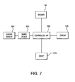
- FIG. 7 is a block diagram of device for measuring and recording operational parameters of a portable forced air heater.
- FIG. 8 is a flow diagram associated with a device for measuring and recording operational parameters of a portable forced air heater.
- a modular frame is assembled and disassembled using interlocked members and snap-lock buttons.
- FIGS. 1 and 2 an exploded view of the preferred modular frame 10 is shown.
- a pair of core members 20 is the central connection point for all other components of the frame 10 .
- Each core member 20 preferably comprises two mating tubes 22 , which are preferably formed as female members.
- the two female mating tubes 22 are preferably permanently connected to the heater as discussed below with reference to FIG. 3 , but may also be removably interconnected with hardware, such as nuts and bolts.
- the two female mating tubes 22 are sized to secure a corresponding male mating tube 28 .
- Each female mating tube 22 includes apertures 24 for receiving the biased member or button 26 of a male mating tube 28 .
- Male mating tube 28 has an outer diameter that is slightly smaller than the inner diameter of the female mating tubes 22 such that a snug fit is achieved and the parts are rigidly assembled.
- the female mating tubes 22 have a 7 ⁇ 8′′ inner diameter and the male mating tubes 28 have a 13/16′′ outer diameter, thereby providing a snug fit.
- the variance in the diameters of the mating tubes 22 and 28 may be selected to achieve a desired rigidity of the frame 10 .
- the overall diameters and thickness of the mating tubes 22 and 28 may again be selected to achieve a desired strength of the frame 10 .
- two handles 30 are U-shaped and include the mating ends 28 with a biased member 26 at each end which complements an aperture 24 upon insertion in a female mating tube 22 of each core member 20 .
- the member 26 upon alignment with aperture 24 , the member 26 is biased upwardly through the aperture 24 locking the male mating ends 28 in place inside the female mating tube 22 .
- the depth of the overlap of the male mating ends 28 and the female mating tube 22 may be selected as desired. However, insertion of at least one third of the length of the male mating ends 28 into the female mating tube 22 is preferred as providing a more rigid assembled frame 10 .
- FIGS. 1 and 2 show a piece of spring metal positioned inside the male mating tube 28 merely as an example, and this is not meant to limit the scope of the present invention.
- Each handle 30 is preferably angled such that a user of the frame 10 may receive the handles at a comfortable height.
- the handles 30 are shown in FIG. 1 as being generally the same size, this is exemplary.
- the handles 30 may be sized as desired based on the size of the forced air heater being supported, the size limitations of an anticipated operating environment, or other size considerations that may arise.
- a support stand 40 which is again preferably U-shaped and includes male mating tubes 28 having members 26 , is inserted into the corresponding female mating tubes 22 of each core member 20 in the same manner as described above.
- Two wheel supports 50 which include male mating tubes 28 having members 26 , complete the frame 10 when inserted into the remaining female mating tubes 22 .
- two wheels 52 are supported by the wheel supports 50 individually by way of an axle 54 .
- the axle 54 is preferably shaped to maintain the spacing between the wheel supports 50 .
- Cap fasteners 56 secure the wheels 52 on the axle 54 .
- the fasteners 56 may be replaced with cotter pins or other securing members.
- the axle 54 may be replaced by spindles that pass through and abut, or are integral with, each support 50 to join each wheel 52 to a support.
- a second support stand 40 may be provided when a wheeled frame is not desired.
- the frame 10 is preferably constructed from tubular steel, but may be constructed from aluminum, titanium, or various other metals as desired.
- FIGS. 3 and 4 show the frame 10 assembled and supporting a forced air heater 60 . While the frame 10 may be removably interconnected to the heater 60 using nuts and bolts, it is preferred that the core members 20 are permanently affixed to the heater 60 , by way of a plurality of weldments 68 , for example. In either case, the flange 62 located on the fuel tank 64 of the forced air heater 60 acts as the attachment point for the core members 20 .
- a projecting handle 70 allows an operator to maneuver the frame 10 , similar to a wheelbarrow. This embodiment is advantageous in that the handle 70 is positioned away from the heater 60 , and provides improved leverage. If desired, the wheels 52 and handle 70 may be reversed.
- core members 120 are tapered to form male mating ends 122 including a biased member 126 for securing a corresponding female mating tube 128 .
- the female mating tubes 128 may rest upon the flange 62 of the fuel tank 64 , increasing the rigidity of the frame and providing a smooth transition between the mating components. It is noted that any combination of male and female mating tubes may be utilized as desired.
- quick assembly frame of the present invention is described herein as supporting a portable forced air heater, it may be used for various other industrial devices that require a portable frame that is quickly and easily assembled.
- a monitor with an activity sensor is coupled with a timing device for measuring operating-time 300 which is further coupled with a controller 150 .
- the controller 150 records the operating-time data in a memory module 130 .
- the controller 150 also records the most recent date of servicing on the memory module 130 .
- a display 140 is also provided so that a user can view the operating-time and service history, the controller 150 accesses the memory and outputs the information onto the display 140 .
- a means to reset 170 the device is provided, so after servicing the display can return to its normal state. By activating the reset operation, the controller 150 adjusts the memory data to accurately reflect the latest servicing information.
- Other embodiments of this invention may contain additional sensors for monitoring activity in addition to or instead of the activity sensor.
- sensors designed to shut the heater off if an unsafe condition occurs or if the safety device fails.
- the photocell sensor to stop the flow of fuel to the combustion chamber if ignition fails or combustion ceases
- a temperature limit sensor to shut down the heater if an overheat condition occurs.
- an activity sensor 160 detects the operation and notifies the controller which begins recording the run or operating-time of the heater 190 which is then stored in the memory 200 .
- the memory 200 is consulted to compare the date of last servicing with the current date and determine if service is necessary.
- the apparatus at the same time or sequentially will also compare the operating-time with a predetermined value 220 and determine whether servicing is necessary. Should either indicate that service is necessary; the display 250 will alert the operator that service is required; otherwise it will operate normally 240 . Possible alerts include a light emitting diode (LED) or a liquid crystal display (LCD) that alerts an operator of required service.
- LED light emitting diode
- LCD liquid crystal display
- the reset function Upon performing maintenance, the reset function is engaged to reset the display which will also update the memory module 260 noting the new service date.
- Potential elements that may need regular servicing on a heater include but are not limited to carbon rotors/vane assembly, air filters, lint filters, spark plugs and nozzles.
- the memory stores a table of maintenance or action items.
- the memory is scanned for potential maintenance issues and to check the status of each service task at each start up.
- the operator can manually call for a memory scan. This feature allows the operator to know in advance about scheduled maintenance or service issues.
- An example of the types of information that may be stored in the memory is displayed in Table 1.
- the memory will record the dates and elapsed operating time since the previous service, each of the items can be reset by engaging the reset button.
- one item may require attention monthly and another may need servicing quarterly. Since the monitor is automatically advance by use or time, the operator is not required to remember different service period or scheduled dates.
- the invention would be equipped to display additional diagnostic information allowing a user to trouble shoot a heater that is performing poorly. Such capabilities include but are not limited to coupling the heater with a sensor for sensing when a heater fails to ignite or burns at unusual combustion performance which would then alert the operator that servicing or maintenance is required.
- a built-in air pressure gauge would display the air pressure setting of the heater allowing the user to determine if the air pressure settings is correct.
- Such diagnostics would assist in the trouble shooting and repair of non-routine replacement items such as motors, printed circuit boards (PCB's), fuses, transformers, etc. in addition to the routine replacement items.
Abstract
Description
| TABLE 1 | ||||
| Elapsed Time | Total | |||
| Type of | Since Most | Running | Next | |
| Action | Date of Most | Recent Repair | Time | Scheduled |
| Required | Recent Repair | (Hours) | (Hours) | Repair |
| Heater | 8/12 | 30.5 | 1400 | 11/12 |
| Servicing | ||||
| Starter | 9/2 | 12 | 1300 | 10/2 |
| Replacement | ||||
| Carbon | 4/5 | 23 | 456 | 5/5 |
| Rotor/Vane | ||||
| Assembly | ||||
| Air Filter | 7/4 | 45 | 700 | 9/4 |
| Nozzle | 9/3 | 6 | 5600 | 12/3 |
Claims (11)
Priority Applications (2)
| Application Number | Priority Date | Filing Date | Title |
|---|---|---|---|
| US11/711,220 US8042784B2 (en) | 2007-02-27 | 2007-02-27 | Mounting frame for portable equipment |
| US12/570,644 US8055478B2 (en) | 2007-02-27 | 2009-09-30 | Maintenance minder for forced air heater |
Applications Claiming Priority (1)
| Application Number | Priority Date | Filing Date | Title |
|---|---|---|---|
| US11/711,220 US8042784B2 (en) | 2007-02-27 | 2007-02-27 | Mounting frame for portable equipment |
Related Child Applications (1)
| Application Number | Title | Priority Date | Filing Date |
|---|---|---|---|
| US12/570,644 Division US8055478B2 (en) | 2007-02-27 | 2009-09-30 | Maintenance minder for forced air heater |
Publications (2)
| Publication Number | Publication Date |
|---|---|
| US20080203267A1 US20080203267A1 (en) | 2008-08-28 |
| US8042784B2 true US8042784B2 (en) | 2011-10-25 |
Family
ID=39714801
Family Applications (2)
| Application Number | Title | Priority Date | Filing Date |
|---|---|---|---|
| US11/711,220 Expired - Fee Related US8042784B2 (en) | 2007-02-27 | 2007-02-27 | Mounting frame for portable equipment |
| US12/570,644 Expired - Fee Related US8055478B2 (en) | 2007-02-27 | 2009-09-30 | Maintenance minder for forced air heater |
Family Applications After (1)
| Application Number | Title | Priority Date | Filing Date |
|---|---|---|---|
| US12/570,644 Expired - Fee Related US8055478B2 (en) | 2007-02-27 | 2009-09-30 | Maintenance minder for forced air heater |
Country Status (1)
| Country | Link |
|---|---|
| US (2) | US8042784B2 (en) |
Cited By (1)
| Publication number | Priority date | Publication date | Assignee | Title |
|---|---|---|---|---|
| US20120187662A1 (en) * | 2009-09-15 | 2012-07-26 | Fillaball Holdings Limited | Apparatus for transporting loads |
Families Citing this family (3)
| Publication number | Priority date | Publication date | Assignee | Title |
|---|---|---|---|---|
| USD672444S1 (en) * | 2012-05-21 | 2012-12-11 | Pinnacle Products International, Inc. | Frame for a forced air heater |
| USD672445S1 (en) * | 2012-05-21 | 2012-12-11 | Pinnacle Products International, Inc. | Forced air heater |
| USD672446S1 (en) * | 2012-05-21 | 2012-12-11 | Pinnacle Products International, Inc. | Enclosure for the end of a forced air heater |
Citations (16)
| Publication number | Priority date | Publication date | Assignee | Title |
|---|---|---|---|---|
| US3645512A (en) * | 1970-05-13 | 1972-02-29 | Scheu Mfg Co | Forced air heater |
| US4404715A (en) | 1981-04-08 | 1983-09-20 | Katsuyama Kinzoku Kogyo Kabushiki Kaisha | Safety-belt buckle of slide-unlocking type |
| USRE31384E (en) * | 1975-12-01 | 1983-09-20 | Harris-Hub Company, Inc. | Bed frame assembly |
| US4443187A (en) * | 1982-06-04 | 1984-04-17 | Koehring Company | Portable heater with integrated control system |
| US4729365A (en) * | 1986-07-21 | 1988-03-08 | Engineered Air Systems, Inc. | Air heating apparatus and method |
| US5388852A (en) | 1992-07-02 | 1995-02-14 | Ampafrance S.A. | Compact folding child's stroller |
| US5505323A (en) * | 1993-10-01 | 1996-04-09 | Kabushiki Kaisha Steel Center | Container capable of being assembled by interlocking connections |
| US6186571B1 (en) * | 1996-06-17 | 2001-02-13 | Malcolm Robert Burke | Vehicle racking system |
| US6375200B1 (en) * | 2000-05-11 | 2002-04-23 | Marshland Enterprises, Llc | Wheeled carrier and seat assembly for use while hunting with decoys |
| US6438810B2 (en) | 1999-12-30 | 2002-08-27 | Delphi Technologies, Inc. | Seat restraint buckle assembly |
| US6694578B1 (en) | 2003-05-15 | 2004-02-24 | Kimberly A. Nicoll | Child safety belt buckle locking mechanism |
| US20040122559A1 (en) * | 1998-03-23 | 2004-06-24 | Cepheid | System and method for temperature control |
| US6830260B2 (en) | 2002-02-20 | 2004-12-14 | Richard C. Everett | Foldable infant jogging stroller |
| US6868583B2 (en) | 2003-03-17 | 2005-03-22 | Chaw Khong Technology Co., Ltd. | Locking pin |
| US20050116055A1 (en) * | 2003-03-21 | 2005-06-02 | Alles Harold G. | Retrofit HVAC zone climate control system |
| US7143912B2 (en) * | 2000-10-16 | 2006-12-05 | Mary Ann Caneba | Customizing pack carrier on wheels |
-
2007
- 2007-02-27 US US11/711,220 patent/US8042784B2/en not_active Expired - Fee Related
-
2009
- 2009-09-30 US US12/570,644 patent/US8055478B2/en not_active Expired - Fee Related
Patent Citations (18)
| Publication number | Priority date | Publication date | Assignee | Title |
|---|---|---|---|---|
| US3645512A (en) * | 1970-05-13 | 1972-02-29 | Scheu Mfg Co | Forced air heater |
| USRE31384E (en) * | 1975-12-01 | 1983-09-20 | Harris-Hub Company, Inc. | Bed frame assembly |
| US4404715A (en) | 1981-04-08 | 1983-09-20 | Katsuyama Kinzoku Kogyo Kabushiki Kaisha | Safety-belt buckle of slide-unlocking type |
| US4443187A (en) * | 1982-06-04 | 1984-04-17 | Koehring Company | Portable heater with integrated control system |
| US4729365A (en) * | 1986-07-21 | 1988-03-08 | Engineered Air Systems, Inc. | Air heating apparatus and method |
| US5388852A (en) | 1992-07-02 | 1995-02-14 | Ampafrance S.A. | Compact folding child's stroller |
| US5505323A (en) * | 1993-10-01 | 1996-04-09 | Kabushiki Kaisha Steel Center | Container capable of being assembled by interlocking connections |
| US6186571B1 (en) * | 1996-06-17 | 2001-02-13 | Malcolm Robert Burke | Vehicle racking system |
| US20040122559A1 (en) * | 1998-03-23 | 2004-06-24 | Cepheid | System and method for temperature control |
| US7188001B2 (en) * | 1998-03-23 | 2007-03-06 | Cepheid | System and method for temperature control |
| US6438810B2 (en) | 1999-12-30 | 2002-08-27 | Delphi Technologies, Inc. | Seat restraint buckle assembly |
| US6375200B1 (en) * | 2000-05-11 | 2002-04-23 | Marshland Enterprises, Llc | Wheeled carrier and seat assembly for use while hunting with decoys |
| US7143912B2 (en) * | 2000-10-16 | 2006-12-05 | Mary Ann Caneba | Customizing pack carrier on wheels |
| US6830260B2 (en) | 2002-02-20 | 2004-12-14 | Richard C. Everett | Foldable infant jogging stroller |
| US6868583B2 (en) | 2003-03-17 | 2005-03-22 | Chaw Khong Technology Co., Ltd. | Locking pin |
| US20050116055A1 (en) * | 2003-03-21 | 2005-06-02 | Alles Harold G. | Retrofit HVAC zone climate control system |
| US6997390B2 (en) * | 2003-03-21 | 2006-02-14 | Home Comfort Zones, Inc. | Retrofit HVAC zone climate control system |
| US6694578B1 (en) | 2003-05-15 | 2004-02-24 | Kimberly A. Nicoll | Child safety belt buckle locking mechanism |
Cited By (1)
| Publication number | Priority date | Publication date | Assignee | Title |
|---|---|---|---|---|
| US20120187662A1 (en) * | 2009-09-15 | 2012-07-26 | Fillaball Holdings Limited | Apparatus for transporting loads |
Also Published As
| Publication number | Publication date |
|---|---|
| US20080203267A1 (en) | 2008-08-28 |
| US20100033335A1 (en) | 2010-02-11 |
| US8055478B2 (en) | 2011-11-08 |
Similar Documents
| Publication | Publication Date | Title |
|---|---|---|
| US8055478B2 (en) | Maintenance minder for forced air heater | |
| EP1770334A2 (en) | Gas fireplace monitoring and control system | |
| US8919706B2 (en) | Gas manifold bracket for gas grill | |
| US9512778B2 (en) | Engine apparatus | |
| AU2015315454B2 (en) | Top ported burner | |
| US20190299234A1 (en) | Modular Design for Pressure Washer Systems | |
| US9863636B2 (en) | Fuel-fired heating appliance having flame indicator assembly | |
| RU63908U1 (en) | SENSOR OF SELECTIVE CONTROL OF THE TORCH OF THE BURNER OF POWER AND WATER BOILERS OF THE MODEL UDF-01 / MI | |
| US20200096195A1 (en) | Atomization burner with flexible fire rate | |
| US7416406B2 (en) | Furnace framework system with expansion joint | |
| CN217055711U (en) | Filter element mounting device and air blower | |
| US4729353A (en) | Fuel container support system for a combustion engine | |
| US9435294B2 (en) | Engine apparatus | |
| JP4042133B2 (en) | Combustion safety device | |
| JP2008097181A (en) | Countermeasure support system | |
| CN218209536U (en) | Denitration combustor of biomass boiler | |
| CN212481276U (en) | Low-nitrogen natural gas burner | |
| CN219101702U (en) | Explosion-proof fan convenient to installation | |
| CN210602243U (en) | Coil pipe type direct-current hot water boiler | |
| US4276018A (en) | Mobile heater | |
| CN220204149U (en) | Axial-flow type fire-fighting smoke exhaust fan with noise reduction structure | |
| KR101831144B1 (en) | Brazier device for roast | |
| JPH04327715A (en) | Liquid fuel combustion device | |
| BR102020000526A2 (en) | Portable automatic pellet burner with remote electronic monitoring | |
| JP6148087B2 (en) | Hot air heater |
Legal Events
| Date | Code | Title | Description |
|---|---|---|---|
| AS | Assignment |
Owner name: PINNACLE PRODUCTS INTERNATIONAL, INC., PENNSYLVANI Free format text: ASSIGNMENT OF ASSIGNORS INTEREST;ASSIGNORS:MCCALLEY, STEVE;HWANG, K. S.;REEL/FRAME:019039/0832 Effective date: 20070213 Owner name: SP ELEMECH, KOREA, REPUBLIC OF Free format text: ASSIGNMENT OF ASSIGNORS INTEREST;ASSIGNORS:MCCALLEY, STEVE;HWANG, K. S.;REEL/FRAME:019039/0832 Effective date: 20070213 Owner name: PINNACLE PRODUCTS INTERNATIONAL, INC.,PENNSYLVANIA Free format text: ASSIGNMENT OF ASSIGNORS INTEREST;ASSIGNORS:MCCALLEY, STEVE;HWANG, K. S.;REEL/FRAME:019039/0832 Effective date: 20070213 Owner name: SP ELEMECH,KOREA, REPUBLIC OF Free format text: ASSIGNMENT OF ASSIGNORS INTEREST;ASSIGNORS:MCCALLEY, STEVE;HWANG, K. S.;REEL/FRAME:019039/0832 Effective date: 20070213 |
|
| AS | Assignment |
Owner name: CITIZENS BANK OF PENNSYLVANIA, PENNSYLVANIA Free format text: SECURITY AGREEMENT;ASSIGNOR:PINNACLE PRODUCTS INTERNATIONAL, INC,;REEL/FRAME:026246/0909 Effective date: 20110506 |
|
| ZAAA | Notice of allowance and fees due |
Free format text: ORIGINAL CODE: NOA |
|
| ZAAB | Notice of allowance mailed |
Free format text: ORIGINAL CODE: MN/=. |
|
| STCF | Information on status: patent grant |
Free format text: PATENTED CASE |
|
| FPAY | Fee payment |
Year of fee payment: 4 |
|
| AS | Assignment |
Owner name: PINNACLE PRODUCTS INTERNATIONAL, INC., PENNSYLVANI Free format text: RELEASE BY SECURED PARTY;ASSIGNOR:CITIZENS BANK OF PENNSYLVANIA;REEL/FRAME:035871/0342 Effective date: 20150522 |
|
| AS | Assignment |
Owner name: FIFTH THIRD BANK, ILLINOIS Free format text: SECURITY INTEREST;ASSIGNOR:PINNACLE PRODUCTS INTERNATIONAL, INC.;REEL/FRAME:035890/0382 Effective date: 20150522 |
|
| AS | Assignment |
Owner name: SPELL CAPITAL MEZZANINE PARTNERS SBIC, LP, MINNESO Free format text: SECURITY INTEREST;ASSIGNOR:PINNACLE PRODUCTS INTERNATIONAL, INC.;REEL/FRAME:036774/0989 Effective date: 20151009 |
|
| AS | Assignment |
Owner name: FIFTH THIRD BANK, ILLINOIS Free format text: SECURITY INTEREST;ASSIGNOR:PINNACLE PRODUCTS INTERNATIONAL, INC.;REEL/FRAME:037063/0620 Effective date: 20151009 |
|
| AS | Assignment |
Owner name: PINNACLE CLIMATE TECHNOLOGIES, INC., PENNSYLVANIA Free format text: CHANGE OF NAME;ASSIGNOR:PINNACLE PRODUCTS INTERNATIONAL, INC.;REEL/FRAME:038426/0961 Effective date: 20151201 |
|
| AS | Assignment |
Owner name: STERLING NATIONAL BANK, TEXAS Free format text: SECURITY AGREEMENT;ASSIGNOR:PINNACLE CLIMATE TECHNOLOGIES, INC.;REEL/FRAME:043988/0679 Effective date: 20170922 |
|
| AS | Assignment |
Owner name: PINNACLE CLIMATE TECHNOLOGIES, INC., MINNESOTA Free format text: RELEASE BY SECURED PARTY;ASSIGNOR:FIFTH THIRD BANK;REEL/FRAME:043960/0279 Effective date: 20170922 |
|
| MAFP | Maintenance fee payment |
Free format text: PAYMENT OF MAINTENANCE FEE, 8TH YR, SMALL ENTITY (ORIGINAL EVENT CODE: M2552); ENTITY STATUS OF PATENT OWNER: SMALL ENTITY Year of fee payment: 8 |
|
| AS | Assignment |
Owner name: INVESTORS BANK, AS AGENT, NEW JERSEY Free format text: SECURITY INTEREST;ASSIGNORS:PINNACLE CLIMATE TECHNOLOGIES, INC. F/K/A PINNACLE PRODUCTS INTRENATIONAL, INC.;SCHAEFER VENTILATION EQUIPMENT CORP.;PPI ACQUISITION GROUP, INC.;REEL/FRAME:057051/0822 Effective date: 20210729 |
|
| FEPP | Fee payment procedure |
Free format text: MAINTENANCE FEE REMINDER MAILED (ORIGINAL EVENT CODE: REM.); ENTITY STATUS OF PATENT OWNER: SMALL ENTITY |
|
| LAPS | Lapse for failure to pay maintenance fees |
Free format text: PATENT EXPIRED FOR FAILURE TO PAY MAINTENANCE FEES (ORIGINAL EVENT CODE: EXP.); ENTITY STATUS OF PATENT OWNER: SMALL ENTITY |
|
| STCH | Information on status: patent discontinuation |
Free format text: PATENT EXPIRED DUE TO NONPAYMENT OF MAINTENANCE FEES UNDER 37 CFR 1.362 |
|
| FP | Lapsed due to failure to pay maintenance fee |
Effective date: 20231025 |