US8043325B2 - Loading device for delivering an embolization coil into a microcatheter - Google Patents
Loading device for delivering an embolization coil into a microcatheter Download PDFInfo
- Publication number
- US8043325B2 US8043325B2 US12/336,586 US33658608A US8043325B2 US 8043325 B2 US8043325 B2 US 8043325B2 US 33658608 A US33658608 A US 33658608A US 8043325 B2 US8043325 B2 US 8043325B2
- Authority
- US
- United States
- Prior art keywords
- lumen
- cannula
- distal
- proximal
- microcatheter
- Prior art date
- Legal status (The legal status is an assumption and is not a legal conclusion. Google has not performed a legal analysis and makes no representation as to the accuracy of the status listed.)
- Expired - Fee Related, expires
Links
- 230000010102 embolization Effects 0.000 title claims abstract description 106
- 239000002184 metal Substances 0.000 claims abstract description 47
- 229910052751 metal Inorganic materials 0.000 claims abstract description 47
- 239000012780 transparent material Substances 0.000 claims abstract description 8
- 239000000463 material Substances 0.000 claims description 6
- 239000012530 fluid Substances 0.000 claims description 4
- 229920003023 plastic Polymers 0.000 claims description 4
- 238000000034 method Methods 0.000 description 9
- BASFCYQUMIYNBI-UHFFFAOYSA-N platinum Chemical compound [Pt] BASFCYQUMIYNBI-UHFFFAOYSA-N 0.000 description 4
- 238000004873 anchoring Methods 0.000 description 3
- 210000001367 artery Anatomy 0.000 description 3
- 230000017531 blood circulation Effects 0.000 description 3
- 230000008321 arterial blood flow Effects 0.000 description 2
- 230000015572 biosynthetic process Effects 0.000 description 2
- -1 e.g. Substances 0.000 description 2
- 239000000835 fiber Substances 0.000 description 2
- 210000002767 hepatic artery Anatomy 0.000 description 2
- 229910052697 platinum Inorganic materials 0.000 description 2
- 229920001343 polytetrafluoroethylene Polymers 0.000 description 2
- 239000004810 polytetrafluoroethylene Substances 0.000 description 2
- 206010002329 Aneurysm Diseases 0.000 description 1
- 208000022211 Arteriovenous Malformations Diseases 0.000 description 1
- 206010053567 Coagulopathies Diseases 0.000 description 1
- 206010028980 Neoplasm Diseases 0.000 description 1
- 239000004952 Polyamide Substances 0.000 description 1
- 239000000853 adhesive Substances 0.000 description 1
- 230000001070 adhesive effect Effects 0.000 description 1
- 229920001871 amorphous plastic Polymers 0.000 description 1
- 230000005744 arteriovenous malformation Effects 0.000 description 1
- 230000000712 assembly Effects 0.000 description 1
- 238000000429 assembly Methods 0.000 description 1
- 239000000560 biocompatible material Substances 0.000 description 1
- 239000008280 blood Substances 0.000 description 1
- 210000004369 blood Anatomy 0.000 description 1
- 210000004204 blood vessel Anatomy 0.000 description 1
- 230000008859 change Effects 0.000 description 1
- 230000035602 clotting Effects 0.000 description 1
- 239000002131 composite material Substances 0.000 description 1
- 230000008878 coupling Effects 0.000 description 1
- 238000010168 coupling process Methods 0.000 description 1
- 238000005859 coupling reaction Methods 0.000 description 1
- 229920001887 crystalline plastic Polymers 0.000 description 1
- 239000003292 glue Substances 0.000 description 1
- 238000003780 insertion Methods 0.000 description 1
- 230000037431 insertion Effects 0.000 description 1
- 230000007794 irritation Effects 0.000 description 1
- 239000007769 metal material Substances 0.000 description 1
- 230000004048 modification Effects 0.000 description 1
- 238000012986 modification Methods 0.000 description 1
- 238000004806 packaging method and process Methods 0.000 description 1
- 239000004033 plastic Substances 0.000 description 1
- 229920002647 polyamide Polymers 0.000 description 1
- 239000004417 polycarbonate Substances 0.000 description 1
- 229920000515 polycarbonate Polymers 0.000 description 1
- 229920001296 polysiloxane Polymers 0.000 description 1
- 230000008569 process Effects 0.000 description 1
- 230000001737 promoting effect Effects 0.000 description 1
- 239000007787 solid Substances 0.000 description 1
- 229910001220 stainless steel Inorganic materials 0.000 description 1
- 239000010935 stainless steel Substances 0.000 description 1
- 230000000472 traumatic effect Effects 0.000 description 1
- 210000003462 vein Anatomy 0.000 description 1
- 230000009278 visceral effect Effects 0.000 description 1
- 230000000007 visual effect Effects 0.000 description 1
- 238000009941 weaving Methods 0.000 description 1
- 238000004804 winding Methods 0.000 description 1
Images


Classifications
-
- A—HUMAN NECESSITIES
- A61—MEDICAL OR VETERINARY SCIENCE; HYGIENE
- A61B—DIAGNOSIS; SURGERY; IDENTIFICATION
- A61B17/00—Surgical instruments, devices or methods, e.g. tourniquets
- A61B17/12—Surgical instruments, devices or methods, e.g. tourniquets for ligaturing or otherwise compressing tubular parts of the body, e.g. blood vessels, umbilical cord
- A61B17/12022—Occluding by internal devices, e.g. balloons or releasable wires
- A61B17/12099—Occluding by internal devices, e.g. balloons or releasable wires characterised by the location of the occluder
- A61B17/12109—Occluding by internal devices, e.g. balloons or releasable wires characterised by the location of the occluder in a blood vessel
-
- A—HUMAN NECESSITIES
- A61—MEDICAL OR VETERINARY SCIENCE; HYGIENE
- A61B—DIAGNOSIS; SURGERY; IDENTIFICATION
- A61B17/00—Surgical instruments, devices or methods, e.g. tourniquets
- A61B17/12—Surgical instruments, devices or methods, e.g. tourniquets for ligaturing or otherwise compressing tubular parts of the body, e.g. blood vessels, umbilical cord
- A61B17/12022—Occluding by internal devices, e.g. balloons or releasable wires
- A61B17/12131—Occluding by internal devices, e.g. balloons or releasable wires characterised by the type of occluding device
- A61B17/1214—Coils or wires
- A61B17/1215—Coils or wires comprising additional materials, e.g. thrombogenic, having filaments, having fibers, being coated
-
- A—HUMAN NECESSITIES
- A61—MEDICAL OR VETERINARY SCIENCE; HYGIENE
- A61B—DIAGNOSIS; SURGERY; IDENTIFICATION
- A61B17/00—Surgical instruments, devices or methods, e.g. tourniquets
- A61B2017/00526—Methods of manufacturing
- A61B2017/0053—Loading magazines or sutures into applying tools
-
- A—HUMAN NECESSITIES
- A61—MEDICAL OR VETERINARY SCIENCE; HYGIENE
- A61B—DIAGNOSIS; SURGERY; IDENTIFICATION
- A61B17/00—Surgical instruments, devices or methods, e.g. tourniquets
- A61B17/12—Surgical instruments, devices or methods, e.g. tourniquets for ligaturing or otherwise compressing tubular parts of the body, e.g. blood vessels, umbilical cord
- A61B17/12022—Occluding by internal devices, e.g. balloons or releasable wires
- A61B2017/1205—Introduction devices
- A61B2017/12054—Details concerning the detachment of the occluding device from the introduction device
- A61B2017/12095—Threaded connection
-
- A—HUMAN NECESSITIES
- A61—MEDICAL OR VETERINARY SCIENCE; HYGIENE
- A61M—DEVICES FOR INTRODUCING MEDIA INTO, OR ONTO, THE BODY; DEVICES FOR TRANSDUCING BODY MEDIA OR FOR TAKING MEDIA FROM THE BODY; DEVICES FOR PRODUCING OR ENDING SLEEP OR STUPOR
- A61M25/00—Catheters; Hollow probes
- A61M25/0021—Catheters; Hollow probes characterised by the form of the tubing
- A61M2025/0042—Microcatheters, cannula or the like having outside diameters around 1 mm or less
Definitions
- the present invention relates to medical devices. More particularly, the invention relates to occluding devices for occluding fluid flow through a body vessel.
- Embolization coils have been used to stop undesired blood flow, such as for example, in the treatment of aneurysms, arteriovenous malformations, traumatic fistulae and tumor embolization. These conditions require that the blood flow through a portion of a body vessel be stopped, for example by introducing an artificial device into the vessel to slow the flow, and by letting the natural clotting process form a more complete blockage of the blood vessel with a clot.
- Embolization coils can be used to form a blockage in a vein or artery to treat conditions like those listed in the foregoing paragraph. These devices have become increasingly common in procedures to block the flow of blood by promoting formation of a clot in a desired location.
- Embolization coils may be made from a bio-compatible material, such as platinum, to minimize the problems associated with tissue irritation and rejection. These coils typically have a pre-coiled tension that correspondingly shapes the coil upon deployment as a complex three dimensional curvy structure that fill in portions of the body vessel and slow blood flow therein.
- polymeric fibers are added to the metallic coils to enhance the coil's thrombogenicity, which is the coil's ability to promote formation of clots.
- Embolization coils are typically introduced into a body vessel by using a microcatheter which extends from a proximal point outside of the patient's body to a distal point near the embolization site.
- a loading device e.g., a metal introducer sheath or cannula, containing the embolization coil is used to carry and protect the coil prior to transferring the embolization coil to the microcatheter for introduction into the patient.
- the loading device may have a small metal stopper or wire stopper that is used to hold the embolization coil within the loading device during packaging and shipping.
- the embolization coil falls out of the loading device prior to being transferred to the microcatheter. If the interventionalist is unaware that the loading device is empty, the occluding procedure may be temporarily performed on the patient without using the embolization coil until the interventionalist realizes the mishap. This will prolong the procedure and possibly present an unnecessary risk to the patient. Accordingly, further improvements and enhances to a device for transferring an embolization coil to a microcatheter for introduction into a patient are desirable.
- a device for delivering an embolization coil into a microcatheter is provided.
- the microcatheter is used to deploy the embolization coil into a body vessel of a patient.
- the device comprises a cannula that has a proximal portion which extends to a distal portion.
- a lumen is formed through the proximal and distal portions of the cannula.
- the distal portion has a distal tip that is formed from metal and is configured to interface with the microcatheter for advancing the embolization coil from the lumen into the microcatheter.
- the proximal portion is at least partially formed of a transparent material for viewing into the lumen to facilitate delivering the embolization coil into the microcatheter.
- the proximal portion of the cannula is at least partially formed of a transparent plastic material and the distal tip is tapered distally.
- the tapered distal tip is for interfacing with a tapered shaped hub of the microcatheter for advancing the embolization coil from the lumen of the cannula into the microcatheter.
- an embolization kit for occluding fluid flow through a body vessel of a patient.
- the kit comprises an embolization coil, a microcatheter and a device for delivering the embolization coil into the microcatheter as discussed in the foregoing paragraphs.
- the embolization coil has a pre-curled tension to facilitate the embolization coil curling within the body vessel when deployed.
- the microcatheter includes a hub and an elongated tube that extends distally from the hub.
- the elongated tube is configured to be positioned in the body vessel to deploy the embolization coil.
- the hub has a tapered wall that defines an opening for receiving the embolization coil and for advancing the embolization coil into the elongated tube.
- FIG. 1 a side view of an embolization coil being deployed from a microcatheter into a body vessel of a patient;
- FIG. 2 a is a side view of a device for delivering an embolization coil in accordance with one embodiment of the present invention
- FIG. 2 b is a side view of a device delivering an embolization coil into a microcatheter in accordance to one embodiment of the present invention
- FIG. 3 a is a perspective view of a distal portion of a device for delivering an embolization coil in accordance with one embodiment of the present invention
- FIG. 3 b is a side view of a cannula section of the device depicted in FIG. 3 a;
- FIG. 3 c is a side view of a metal sheath of the device depicted in FIG. 3 a;
- FIG. 3 d is a sectional view of the metal sheath depicted in FIG. 3 c;
- FIG. 3 e is a cross-sectional view of the device depicted in FIG. 3 a;
- FIG. 4 a is a cannula section of a device for delivering an embolization coil in accordance with an embodiment of the present invention
- FIG. 4 b is a metal sheath of a device for delivering an embolization coil in accordance with an embodiment of the present invention
- FIG. 4 c is a cross-sectional view of the cannula section depicted in FIG. 4 a;
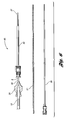
- FIG. 5 is an exploded side view of a device for delivering an embolization coil in accordance with one embodiment of the present invention.
- FIG. 6 is a side view of an embolization kit in accordance with an embodiment of the present invention.
- the present invention seeks to overcome some of the problems associated with delivering an embolization coil into a microcatheter for introduction into a body vessel of a patient.
- the present invention provides a device for carrying the embolization coil and for delivering the embolization coil into a microcatheter that facilitates an interventionalist being able to detect whether an embolization coil is present in the device or, for example, has accidentally fallen out of the device.
- the device has a lumen for carrying the embolization coil and for advancing the embolization coil from the device.
- the device also has a transparent section surrounding at least a portion of the lumen that allows the interventionalist to view into the lumen to determine whether or not the embolization coil is present within the device prior to and/or during delivery of the embolization coil into the microcatheter.
- multiple embolization coils 2 and 4 may be used to occlude a body vessel 6 of a patient.
- the embolization coils 2 and 4 are deployed into the body vessel 6 from a microcatheter 8 .
- a high radial force embolization coil 2 is initially deployed within the body vessel 6 to form an embolization anchor within the body vessel 6 .
- the relatively high radial force of the anchoring coil 2 pushes against the wall of the body vessel 6 to resist further advancement through the body vessel 6 from forces generated by arterial blood flow.
- a soft embolization coil 4 (e.g. relatively intermediate or low radial force) is deployed adjacent to the high radial force embolization coil 2 to fill in various gaps that may exist between the curled configuration of the high radial force embolization coil 2 .
- Various weaving or moving techniques may be used to deploy the embolization coils 2 and 4 , such as for example, a coaxial technique to prevent coil elongation, a scaffold technique or an anchor technique. Other suitable techniques known to those skilled in the art for deploying embolization coils may also be used.
- sufficient arterial blood flow remains to hold the soft embolization coil 4 against the anchoring embolization coil 2 until a solid clot ensures a permanent fixation.
- a device 10 for delivering an embolization coil 2 and 4 into a microcatheter 8 for deployment therefrom comprises a cannula 12 .
- the cannula 12 has a proximal portion 14 that extends to a distal portion 16 .
- a lumen 18 is formed through the cannula 12 extending through the proximal and distal portions 14 and 16 .
- the cannula 12 is used to carry and protect the embolization coil 2 and 4 , which is contained in the lumen 18 , prior to being transferred into the microcatheter 8 .
- the distal portion 16 has a distal tip 22 that interfaces with the microcatheter 8 for advancing the embolization coil 2 and 4 from the lumen 18 into the microcatheter 8 .
- the microcatheter 8 has a hub 34 , which may be made from a transparent material, at its proximal end 35 and an elongated tube 36 that extends distally from the hub 34 for positioning in the body vessel 6 .
- the hub 34 has a tapered wall 38 that defines an opening 40 for receiving the distal tip 22 and for transferring the embolization coil 2 and 4 from the device 10 .
- the distal tip 22 is preferably tapered distally to match the tapered wall 38 of the hub 34 to facilitate a tight engagement with the microcatheter 8 . Once received, the embolization coil 2 and 4 is advanced into the elongated tube 36 .
- the distal tip 22 is formed from metal, e.g., stainless steel.
- the relatively high strength of the metal that forms the thinly tapered distal tip 22 provides sufficient structure to the distal tip 22 for being forcibly engaged with the microcatheter 8 without breaking or becoming deformed to ensure proper transfer of the embolization coil 2 and 4 into the microcatheter 8 .
- the cannula 12 is at least partially formed from a transparent material, e.g., amorphous plastic such as clear polycarbonate or a semi-crystalline plastic such as a relatively clear, translucent polyamide.
- a transparent material e.g., amorphous plastic such as clear polycarbonate or a semi-crystalline plastic such as a relatively clear, translucent polyamide.
- the transparent material forms the proximal portion 14 and part of the distal portion 16 , which is also covered by the metal material that extends proximally from the distal tip 22 .
- An opening 19 may be formed in the metal overlying the transparent material to form a window 20 for viewing through the transparent material into the lumen 18 to facilitate delivery of the embolization coil 2 and 4 into the microcatheter 8 .
- the device 10 may further include a hub 24 that is disposed opposite the distal tip 22 at the proximal end of the proximal portion 14 . Adjacent to the hub 24 , the device 10 may also include an adjustable luer fitting 26 . The fitting 26 may be advanced along the cannula 12 between the hub 24 and the distal tip 22 and is rotatable to couple with the hub 34 of the microcatheter 8 . Coupling the cannula 12 with the microcatheter 8 preferably stabilizes the device 10 with the microcatheter 8 ensuring proper transfer of the embolization coil 2 and 4 .
- a stopper 28 e.g., a wire stopper, may be used to keep the embolization coil 2 and 4 within the device 10 .
- ends 30 of the wire stopper 28 corresponding obstruct the proximal and distal ends of the lumen 18 .
- a stopper body 32 that extends between the ends 30 is disposed outside the device 10 where it may be manipulated by the interventionalist to remove the ends 30 from the lumen 18 to release the embolization coil 2 and 4 contained therein.
- the cannula 12 comprises a clear cannula section 42 and a metal sheath 44 .
- the metal sheath 44 is disposed adjacent to a distal end portion 46 of the clear cannula section 42 .
- the metal sheath 44 forms at least part of the distal portion 16 of the cannula 12 and includes the distal tip 22 .
- the clear cannula section 42 forms at least part of the proximal portion 14 of a cannula 12 .
- the clear cannula section 42 and the metal sheath 44 are affixed together, e.g., via glue or adhesive.
- the metal sheath 44 has an outer perimeter body 48 that extends proximally from the distal tip 22 .
- the outer perimeter body 48 may be relatively thin and disposed about at least a distal end portion 46 of the clear cannula section 42 . This configuration may provide a relatively large surface area for bonding the metal sheath 44 to the clear cannula section 42 and further enhance the structure of the cannula 12 by providing a layered composite structure (see FIG. 3 e ).
- the outer perimeter body 48 substantially covers the length of the cannula section 42 adjacent to the hub 24 .
- the window 20 as discussed in the foregoing paragraphs may be defined by an opening 19 formed in the metal sheath 44 .
- the opening 19 overlies the distal end portion 46 of the clear cannula section 42 to form the window 20 for viewing into the lumen 18 .
- the outer perimeter body 48 of the metal sheath 44 has a proximal lumen 52 formed therethrough.
- the distal tip 22 of the metal sheath 44 has a distal lumen 54 formed therethrough that extends to the proximal lumen 52 .
- the proximal lumen 52 has a larger diameter 56 relative to a diameter 58 of the distal lumen 58 such that a step 60 is formed in the metal sheath 44 adjacent to where the proximal and distal lumens 52 and 54 intersect.
- the distal end portion 46 of the clear cannula section 42 is positioned in the proximal lumen 52 so as to be contiguous with the step 60 .
- the clear cannula section 42 has a lumen 62 that is aligned with the distal lumen 54 of the distal tip 22 to define the lumen 18 of the cannula 12 .
- FIGS. 4 a - 4 c illustrate an embodiment similar to the embodiments depicted in FIGS. 3 a - 3 e except for the following.
- the outer perimeter body 48 of the metal sheath 44 may have a relatively short length that covers only the distal end portion 46 of the clear cannula section 42 . As such, no opening may be formed in the outer perimeter body 48 that defines a window for viewing into the lumen 18 . Rather, because of the relatively short length of the outer perimeter body 48 , a substantial length along the clear cannula section 42 is available to provide the interventionalist with visual contact with the lumen 18 . Preferably, sufficient surface area between the clear cannula section 42 and the outer perimeter body 48 is available to provide for suitable bonding therebetween.
- FIG. 5 illustrates another embodiment similar to the embodiments depicted in FIGS. 4 a - 4 c except for the following.
- the metal sheath 44 abuts the clear cannula section 42 at corresponding proximal and distal ends 64 and 66 .
- the ends 64 and 66 are bonded together to form the cannula 12 .
- the metal sheath 44 and the clear cannula section 42 have substantially the same size lumens 52 and 62 that are aligned to form the lumen 18 of the cannula 12 .
- FIG. 6 illustrates at least one embodiment of an embolization kit 80 .
- the kit 80 includes a microcatheter 8 , preferably made from a soft, flexible material such as silicone or any other suitable material.
- the microcatheter 8 has a proximal end 35 , a distal end 37 , and a plastic adapter or hub 24 to receive an embolization coil 2 and 4 from the delivery device 10 .
- the inside diameter of the microcatheter 8 may range between 0.014 and 0.027 inches.
- the kit 80 may further include a guide wire 82 which provides a guide catheter 84 a path during insertion of the guide catheter 84 within the body vessel 6 .
- the size of the guide wire 82 is based on the inside diameter of the guide catheter 84 .
- the kit 80 further includes a polytetrafluoroethylene (PTFE) guide catheter 84 or sheath for percutaneously introducing the microcatheter 8 into the body vessel 6 .
- PTFE polytetrafluoroethylene
- the guide catheter 84 may have a size between about 4-French to 8-French and allows the microcatheter 8 to be inserted therethrough to a desired location in the body vessel 6 .
- the guide catheter 84 receives the microcatheter 8 and provides stability of the microcatheter 8 at a desired location within the body vessel 6 .
- the guide catheter 84 may stay stationary within a common visceral artery, e.g., a common hepatic artery, and add stability to the microcatheter 8 as the microcatheter 8 is advanced through the guide catheter 84 to a point of occlusion in the connecting artery, e.g., the left or right hepatic artery.
- the embolization coil 2 and 4 is loaded from the delivery device 10 at the proximal end 35 of the microcatheter and the embolization coil 2 and 4 is advanced through the microcatheter 8 for deployment through the distal end 37 .
- a push wire 86 is used to mechanically advance or push the embolization coil 2 and 4 through the microcatheter 8 .
- the size of the push wire 86 depends on the diameter of the microcatheter 8 .
- embolization coil 2 and 4 when the embolization coil 2 and 4 is deployed in the body vessel 6 , and anchoring embolization coil 2 may serve to hold in place against the inner wall of the body vessel 6 and subsequently softer embolization coils 4 (e.g. made from platinum) with fibers may be further deployed to serve to occlude fluid flow by filling the lumen of the body vessel 6 .
- embolization coils 4 e.g. made from platinum
- an elongated releasing member (not shown) may be used instead of a push wire 86 .
- the elongated releasing member is similar to the push wire 86 in that it may be advanced through the microcatheter 8 to deploy the embolization coil 2 and 4 through the distal end 37 .
- the elongated releasing member further includes a distal end configured for selectively engaging with the embolization coil 2 and 4 .
- the distal end of the elongated releasing member may have threads which engage with the wire windings of an embolization coil 2 and 4 .
- the elongated releasing member may be twisted or unscrewed to disengage the embolization coil 2 and 4 from the elongated releasing member, thus releasing the embolization coil 2 and 4 within the body vessel 6 .
- Other suitable releasing devices known to those skilled in the art may be used to advance and selectively deploy the embolization coil 2 and 4 from the microcatheter 8 .
- body cavity embolization kit described above is merely one example of a kit that may be used to deploy an embolization coil in a body vessel.
- other kits, assemblies, and systems may be used to deploy an embodiment of the embolization coil without falling beyond the scope or spirit of the present invention.
Abstract
Description
Claims (20)
Priority Applications (1)
| Application Number | Priority Date | Filing Date | Title |
|---|---|---|---|
| US12/336,586 US8043325B2 (en) | 2008-12-17 | 2008-12-17 | Loading device for delivering an embolization coil into a microcatheter |
Applications Claiming Priority (1)
| Application Number | Priority Date | Filing Date | Title |
|---|---|---|---|
| US12/336,586 US8043325B2 (en) | 2008-12-17 | 2008-12-17 | Loading device for delivering an embolization coil into a microcatheter |
Publications (2)
| Publication Number | Publication Date |
|---|---|
| US20100152650A1 US20100152650A1 (en) | 2010-06-17 |
| US8043325B2 true US8043325B2 (en) | 2011-10-25 |
Family
ID=42241399
Family Applications (1)
| Application Number | Title | Priority Date | Filing Date |
|---|---|---|---|
| US12/336,586 Expired - Fee Related US8043325B2 (en) | 2008-12-17 | 2008-12-17 | Loading device for delivering an embolization coil into a microcatheter |
Country Status (1)
| Country | Link |
|---|---|
| US (1) | US8043325B2 (en) |
Cited By (3)
| Publication number | Priority date | Publication date | Assignee | Title |
|---|---|---|---|---|
| US9427219B2 (en) | 2012-11-19 | 2016-08-30 | Cook Medical Technologies Llc | Delivery device for vascular occluding device |
| US20170231716A1 (en) * | 2014-11-06 | 2017-08-17 | Devicor Medical Products, Inc. | Spring-ejected biopsy marker |
| US10188396B2 (en) | 2012-08-06 | 2019-01-29 | Covidien Lp | Apparatus and method for delivering an embolic composition |
Families Citing this family (7)
| Publication number | Priority date | Publication date | Assignee | Title |
|---|---|---|---|---|
| EP2234562B1 (en) | 2007-12-21 | 2019-02-27 | MicroVention, Inc. | A system and method of detecting implant detachment |
| EP2231030B1 (en) | 2007-12-21 | 2019-02-27 | MicroVention, Inc. | System and method for locating detachment zone of a detachable implant |
| US8795319B2 (en) | 2011-03-02 | 2014-08-05 | Cook Medical Technologies Llc | Embolization coil |
| US9498226B2 (en) | 2011-09-16 | 2016-11-22 | Cook Medical Technologies, LLC | Embolic coil delivery system |
| US9358070B2 (en) | 2012-01-26 | 2016-06-07 | Cook Medical Technologies Llc | Medical device package and methods |
| GB2509952B (en) * | 2013-01-18 | 2015-01-28 | Cook Medical Technologies Llc | Medical device loading and carrier tool |
| WO2022237605A1 (en) * | 2021-05-10 | 2022-11-17 | 杭州德诺脑神经医疗科技有限公司 | Delivery system |
Citations (28)
| Publication number | Priority date | Publication date | Assignee | Title |
|---|---|---|---|---|
| US5066277A (en) * | 1990-07-09 | 1991-11-19 | Safe Medical Devices, Inc. | Protective system for safe disposition of a hypodermic syringe device |
| US5163903A (en) * | 1989-01-27 | 1992-11-17 | C. R. Bard, Inc. | Catheter exchange system with detachable luer fitting |
| US5350397A (en) * | 1992-11-13 | 1994-09-27 | Target Therapeutics, Inc. | Axially detachable embolic coil assembly |
| US5382260A (en) | 1992-10-30 | 1995-01-17 | Interventional Therapeutics Corp. | Embolization device and apparatus including an introducer cartridge and method for delivering the same |
| US5707389A (en) * | 1995-06-07 | 1998-01-13 | Baxter International Inc. | Side branch occlusion catheter device having integrated endoscope for performing endoscopically visualized occlusion of the side branches of an anatomical passageway |
| US5782810A (en) | 1995-11-22 | 1998-07-21 | O'donnell; Miles C. | Multipart radiopaque and/or magnetically detectable tube catheter and method of fabrication thereof |
| US5895410A (en) * | 1997-09-12 | 1999-04-20 | B. Braun Medical, Inc. | Introducer for an expandable vascular occlusion device |
| US5984944A (en) * | 1997-09-12 | 1999-11-16 | B. Braun Medical, Inc. | Introducer for an expandable vascular occlusion device |
| US6033413A (en) | 1998-04-20 | 2000-03-07 | Endocare, Inc. | Stent delivery system |
| US6096022A (en) * | 1995-08-31 | 2000-08-01 | Target Therapeutics Inc. | Bi-directional catheter |
| US6178968B1 (en) | 1995-06-07 | 2001-01-30 | Edwards Lifesciences Corp. | Method of endoscopically visualized occlusion of the side branches of an anatomical passageway |
| US6203547B1 (en) * | 1997-12-19 | 2001-03-20 | Target Therapeutics, Inc. | Vaso-occlusion apparatus having a manipulable mechanical detachment joint and a method for using the apparatus |
| US6221081B1 (en) | 1998-09-14 | 2001-04-24 | Endocare, Inc. | Insertion device for stents and methods for use |
| US6458137B1 (en) * | 1999-05-26 | 2002-10-01 | Cook Incorporated | Assembly for positioning an embolization coil in the vascular system and a method of introducing a detachable embolization coil |
| US20030153926A1 (en) | 2002-02-08 | 2003-08-14 | Reinhold Schmieding | Distracting cannula for sheathless arthroscope |
| US6726712B1 (en) * | 1999-05-14 | 2004-04-27 | Boston Scientific Scimed | Prosthesis deployment device with translucent distal end |
| US20040097780A1 (en) * | 2000-12-15 | 2004-05-20 | Kawasumi Laboratories, Inc. | Cartridge for marker delivery device and marker delivery device |
| US6752827B2 (en) | 2001-12-04 | 2004-06-22 | Vasca, Inc. | Devices, systems, and methods for subcutaneously placing an article |
| US20040267281A1 (en) | 2003-06-25 | 2004-12-30 | Eran Harari | Delivery system for self-expandable diverter |
| US20050049609A1 (en) | 2004-08-06 | 2005-03-03 | Scimed Life Systems, Inc. | Medical device delivery systems |
| US6942688B2 (en) | 2000-02-29 | 2005-09-13 | Cordis Corporation | Stent delivery system having delivery catheter member with a clear transition zone |
| US20070043421A1 (en) * | 2005-05-13 | 2007-02-22 | Alveolus, Inc. | Delivery device with shortened inner tube and associated method |
| US20070112361A1 (en) * | 2005-11-07 | 2007-05-17 | Schonholz Steven M | Surgical repair systems and methods of using the same |
| US20070142893A1 (en) * | 2005-12-19 | 2007-06-21 | Buiser Marcia S | Embolic coils |
| US20070287957A1 (en) * | 2006-04-17 | 2007-12-13 | Cook Incorporated | Endovascular device tip assembly incorporating a marker device and method for making the same |
| US20080103581A1 (en) * | 2006-10-19 | 2008-05-01 | Olympus Medical Systems Corp. | Stent delivery system |
| US7367980B2 (en) * | 2004-04-28 | 2008-05-06 | Boston Scientific Scimed, Inc. | Introducer sheath stabilizer |
| US20090054905A1 (en) * | 2007-05-22 | 2009-02-26 | Wilson-Cook Medical Inc. | Embolization coil delivery systems and methods |
-
2008
- 2008-12-17 US US12/336,586 patent/US8043325B2/en not_active Expired - Fee Related
Patent Citations (32)
| Publication number | Priority date | Publication date | Assignee | Title |
|---|---|---|---|---|
| US5163903A (en) * | 1989-01-27 | 1992-11-17 | C. R. Bard, Inc. | Catheter exchange system with detachable luer fitting |
| US5066277A (en) * | 1990-07-09 | 1991-11-19 | Safe Medical Devices, Inc. | Protective system for safe disposition of a hypodermic syringe device |
| US5746734A (en) | 1992-10-30 | 1998-05-05 | International Therapeutics Corporation | Introducer cartridge for delivering an embolization device |
| US5382260A (en) | 1992-10-30 | 1995-01-17 | Interventional Therapeutics Corp. | Embolization device and apparatus including an introducer cartridge and method for delivering the same |
| US5476472A (en) * | 1992-10-30 | 1995-12-19 | Interventional Therapeutics Corporation | Embolization device and apparatus including an introducer cartridge and a delivery catheter and method for delivering the embolization device |
| US5891130A (en) * | 1992-11-13 | 1999-04-06 | Target Therapeutics, Inc. | Axially detachable embolic coil assembly |
| US5350397A (en) * | 1992-11-13 | 1994-09-27 | Target Therapeutics, Inc. | Axially detachable embolic coil assembly |
| US5707389A (en) * | 1995-06-07 | 1998-01-13 | Baxter International Inc. | Side branch occlusion catheter device having integrated endoscope for performing endoscopically visualized occlusion of the side branches of an anatomical passageway |
| US5947994A (en) | 1995-06-07 | 1999-09-07 | Baxter International Inc. | Endoscopically-assisted device for endoluminal occlusion of anatomical passageway side branches |
| US6178968B1 (en) | 1995-06-07 | 2001-01-30 | Edwards Lifesciences Corp. | Method of endoscopically visualized occlusion of the side branches of an anatomical passageway |
| US6096022A (en) * | 1995-08-31 | 2000-08-01 | Target Therapeutics Inc. | Bi-directional catheter |
| US5782810A (en) | 1995-11-22 | 1998-07-21 | O'donnell; Miles C. | Multipart radiopaque and/or magnetically detectable tube catheter and method of fabrication thereof |
| US5895410A (en) * | 1997-09-12 | 1999-04-20 | B. Braun Medical, Inc. | Introducer for an expandable vascular occlusion device |
| US5984944A (en) * | 1997-09-12 | 1999-11-16 | B. Braun Medical, Inc. | Introducer for an expandable vascular occlusion device |
| US6203547B1 (en) * | 1997-12-19 | 2001-03-20 | Target Therapeutics, Inc. | Vaso-occlusion apparatus having a manipulable mechanical detachment joint and a method for using the apparatus |
| US6033413A (en) | 1998-04-20 | 2000-03-07 | Endocare, Inc. | Stent delivery system |
| US6221081B1 (en) | 1998-09-14 | 2001-04-24 | Endocare, Inc. | Insertion device for stents and methods for use |
| US6726712B1 (en) * | 1999-05-14 | 2004-04-27 | Boston Scientific Scimed | Prosthesis deployment device with translucent distal end |
| US6458137B1 (en) * | 1999-05-26 | 2002-10-01 | Cook Incorporated | Assembly for positioning an embolization coil in the vascular system and a method of introducing a detachable embolization coil |
| US6942688B2 (en) | 2000-02-29 | 2005-09-13 | Cordis Corporation | Stent delivery system having delivery catheter member with a clear transition zone |
| US20040097780A1 (en) * | 2000-12-15 | 2004-05-20 | Kawasumi Laboratories, Inc. | Cartridge for marker delivery device and marker delivery device |
| US6752827B2 (en) | 2001-12-04 | 2004-06-22 | Vasca, Inc. | Devices, systems, and methods for subcutaneously placing an article |
| US20030153926A1 (en) | 2002-02-08 | 2003-08-14 | Reinhold Schmieding | Distracting cannula for sheathless arthroscope |
| US20040267281A1 (en) | 2003-06-25 | 2004-12-30 | Eran Harari | Delivery system for self-expandable diverter |
| US7367980B2 (en) * | 2004-04-28 | 2008-05-06 | Boston Scientific Scimed, Inc. | Introducer sheath stabilizer |
| US20050049609A1 (en) | 2004-08-06 | 2005-03-03 | Scimed Life Systems, Inc. | Medical device delivery systems |
| US20070043421A1 (en) * | 2005-05-13 | 2007-02-22 | Alveolus, Inc. | Delivery device with shortened inner tube and associated method |
| US20070112361A1 (en) * | 2005-11-07 | 2007-05-17 | Schonholz Steven M | Surgical repair systems and methods of using the same |
| US20070142893A1 (en) * | 2005-12-19 | 2007-06-21 | Buiser Marcia S | Embolic coils |
| US20070287957A1 (en) * | 2006-04-17 | 2007-12-13 | Cook Incorporated | Endovascular device tip assembly incorporating a marker device and method for making the same |
| US20080103581A1 (en) * | 2006-10-19 | 2008-05-01 | Olympus Medical Systems Corp. | Stent delivery system |
| US20090054905A1 (en) * | 2007-05-22 | 2009-02-26 | Wilson-Cook Medical Inc. | Embolization coil delivery systems and methods |
Cited By (3)
| Publication number | Priority date | Publication date | Assignee | Title |
|---|---|---|---|---|
| US10188396B2 (en) | 2012-08-06 | 2019-01-29 | Covidien Lp | Apparatus and method for delivering an embolic composition |
| US9427219B2 (en) | 2012-11-19 | 2016-08-30 | Cook Medical Technologies Llc | Delivery device for vascular occluding device |
| US20170231716A1 (en) * | 2014-11-06 | 2017-08-17 | Devicor Medical Products, Inc. | Spring-ejected biopsy marker |
Also Published As
| Publication number | Publication date |
|---|---|
| US20100152650A1 (en) | 2010-06-17 |
Similar Documents
| Publication | Publication Date | Title |
|---|---|---|
| US8043325B2 (en) | Loading device for delivering an embolization coil into a microcatheter | |
| AU2018220001B2 (en) | Occlusive device delivery system with mechanical detachment | |
| US20220304697A1 (en) | Occlusive implants with fiber-based release structures | |
| US10206685B2 (en) | Systems, devices, and methods for delivering a lumen occlusion device using distal and/or proximal control | |
| US9486223B2 (en) | Mechanically datachable vaso-occlusive device | |
| US20080306503A1 (en) | Mechanically detachable vaso-occlusive device | |
| US8834515B2 (en) | Mechanically detachable vaso-occlusive device | |
| JP4805162B2 (en) | Hemostatic device | |
| US20080119887A1 (en) | Mechanically detachable vaso-occlusive device | |
| CA2276731C (en) | Hemostatic puncture closure device | |
| CN108348258B (en) | Device and method for delivering an implant to a vascular condition | |
| US20230067426A1 (en) | Detection and pressure relief for percutaneous closure of a vessel | |
| CN116096324A (en) | Device for implanting a medical implant into a human or animal body |
Legal Events
| Date | Code | Title | Description |
|---|---|---|---|
| AS | Assignment |
Owner name: COOK INCORPORATED,INDIANA Free format text: ASSIGNMENT OF ASSIGNORS INTEREST;ASSIGNOR:SCHRODT, BENJAMIN TAYLOR;REEL/FRAME:021991/0249 Effective date: 20081216 Owner name: COOK INCORPORATED, INDIANA Free format text: ASSIGNMENT OF ASSIGNORS INTEREST;ASSIGNOR:SCHRODT, BENJAMIN TAYLOR;REEL/FRAME:021991/0249 Effective date: 20081216 |
|
| ZAAA | Notice of allowance and fees due |
Free format text: ORIGINAL CODE: NOA |
|
| ZAAB | Notice of allowance mailed |
Free format text: ORIGINAL CODE: MN/=. |
|
| AS | Assignment |
Owner name: COOK MEDICAL TECHNOLOGIES LLC, INDIANA Free format text: ASSIGNMENT OF ASSIGNORS INTEREST;ASSIGNOR:COOK INCORPORATED;REEL/FRAME:026941/0087 Effective date: 20110817 |
|
| STCF | Information on status: patent grant |
Free format text: PATENTED CASE |
|
| FPAY | Fee payment |
Year of fee payment: 4 |
|
| MAFP | Maintenance fee payment |
Free format text: PAYMENT OF MAINTENANCE FEE, 8TH YEAR, LARGE ENTITY (ORIGINAL EVENT CODE: M1552); ENTITY STATUS OF PATENT OWNER: LARGE ENTITY Year of fee payment: 8 |
|
| FEPP | Fee payment procedure |
Free format text: MAINTENANCE FEE REMINDER MAILED (ORIGINAL EVENT CODE: REM.); ENTITY STATUS OF PATENT OWNER: LARGE ENTITY |
|
| LAPS | Lapse for failure to pay maintenance fees |
Free format text: PATENT EXPIRED FOR FAILURE TO PAY MAINTENANCE FEES (ORIGINAL EVENT CODE: EXP.); ENTITY STATUS OF PATENT OWNER: LARGE ENTITY |
|
| STCH | Information on status: patent discontinuation |
Free format text: PATENT EXPIRED DUE TO NONPAYMENT OF MAINTENANCE FEES UNDER 37 CFR 1.362 |
|
| FP | Lapsed due to failure to pay maintenance fee |
Effective date: 20231025 |