US8044838B1 - Methods and systems for determining the phase constant for a dielectric medium - Google Patents
Methods and systems for determining the phase constant for a dielectric medium Download PDFInfo
- Publication number
- US8044838B1 US8044838B1 US12/190,738 US19073808A US8044838B1 US 8044838 B1 US8044838 B1 US 8044838B1 US 19073808 A US19073808 A US 19073808A US 8044838 B1 US8044838 B1 US 8044838B1
- Authority
- US
- United States
- Prior art keywords
- dielectric medium
- calibration object
- spectral response
- calibration
- deployed
- Prior art date
- Legal status (The legal status is an assumption and is not a legal conclusion. Google has not performed a legal analysis and makes no representation as to the accuracy of the status listed.)
- Active, expires
Links
Images


Classifications
-
- G—PHYSICS
- G01—MEASURING; TESTING
- G01V—GEOPHYSICS; GRAVITATIONAL MEASUREMENTS; DETECTING MASSES OR OBJECTS; TAGS
- G01V3/00—Electric or magnetic prospecting or detecting; Measuring magnetic field characteristics of the earth, e.g. declination, deviation
- G01V3/15—Electric or magnetic prospecting or detecting; Measuring magnetic field characteristics of the earth, e.g. declination, deviation specially adapted for use during transport, e.g. by a person, vehicle or boat
- G01V3/17—Electric or magnetic prospecting or detecting; Measuring magnetic field characteristics of the earth, e.g. declination, deviation specially adapted for use during transport, e.g. by a person, vehicle or boat operating with electromagnetic waves
-
- G—PHYSICS
- G01—MEASURING; TESTING
- G01S—RADIO DIRECTION-FINDING; RADIO NAVIGATION; DETERMINING DISTANCE OR VELOCITY BY USE OF RADIO WAVES; LOCATING OR PRESENCE-DETECTING BY USE OF THE REFLECTION OR RERADIATION OF RADIO WAVES; ANALOGOUS ARRANGEMENTS USING OTHER WAVES
- G01S13/00—Systems using the reflection or reradiation of radio waves, e.g. radar systems; Analogous systems using reflection or reradiation of waves whose nature or wavelength is irrelevant or unspecified
- G01S13/74—Systems using reradiation of radio waves, e.g. secondary radar systems; Analogous systems
Definitions
- the field of the disclosure relates generally to the detection of objects using resonant radio frequency location, and more specifically, to methods and systems for determining the phase constant of a dielectric medium within which such objects could be embedded.
- RF radio frequency
- the reflected spectral response, including the resonant frequencies, of a buried object cannot reliably be predicted, and resonant RF location cannot be effectively used to detect and identify the object.
- the permeability, permittivity, and phase constant typically cannot be measured without access to a sample of the medium. Furthermore, the dielectric properties of certain media vary with conditions such as bulk density, water content, and composition. Thus, a permeability, permittivity, or phase constant measurement taken at one time cannot be used reliably to determine the spectral response of an embedded object at another time.
- a method for remotely determining the phase constant for a dielectric medium includes deploying a calibration object with a known free-space spectral response within a dielectric medium of interest, determining the spectral response of the calibration object deployed in the dielectric medium, and determining the phase constant for the dielectric medium using a relationship between the free-space spectral response of the calibration object and the spectral response of the calibration object when deployed in the dielectric medium.
- Another aspect is directed to a system for determining the phase constant for a dielectric medium including a calibration object having a known free-space spectral response and capable of being deployed within a dielectric medium for which the phase constant is to be determined.
- the system also includes at least one transmitter, at least one receiver, the transmitter and receiver operable to determine a resonant frequency response of the calibration object when deployed within the dielectric medium, and a processor operable to determine the phase constant for the dielectric medium utilizing the known free-space spectral response and the resonant frequency response of the calibration object within the dielectric medium.
- FIG. 1 is a view of a system for determining the phase constant of a dielectric medium.
- FIG. 2 is a schematic view of a detection device for the system of FIG. 1 .
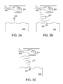
- FIGS. 3A-3C are schematic views of a method for determining the phase constant of a dielectric medium.
- FIG. 4 is a flowchart of a method for determining the phase constant of a dielectric medium.
- the herein described methods and systems provide a discriminating capability to resonant RF location techniques which are useful in applications that extend from concealed weapons detection to navigation.
- Example applications include, but are not limited to, extended range metallic and non-metallic detection, concealed weapons detection, particle detection in the processing of drugs, foods, textiles, etc., ranging with passive targets, GPS denied navigation, and covert electronic fences that are up to 100 meters in depth.
- Addition of the above described capabilities to known resonant RF locating techniques results in a relatively inexpensive product that provides improved performance in these applications.
- FIG. 1 is an illustration of an exemplary system 10 for determining the phase constant of a dielectric medium.
- an air vehicle 12 is located above a medium of interest.
- a calibration object 16 is located in the medium of interest, which is referred to herein as a dielectric medium 14 .
- a ground vehicle and a water vehicle could be utilized as well as a permanent ground-based location, which may be referred to herein as a base station or permanent station.
- the calibration object 16 is configured to have a known free-space spectral response that is associated with a known free-space resonant frequency.
- the calibration object 16 is configured such that it is capable of being deployed into the dielectric medium 14 , for example, in the configuration of a projectile.
- the calibration object 16 housed within a housing and the free-space resonant frequency of the combination is known, and the housing is configured to be deployed into the dielectric medium 14 as a projectile.
- the calibration object 16 housed within a housing and deployed from the housing into the dielectric medium 14 such that the housing does not affect a spectral response of the calibration object.
- the system may include additional calibration objects 20 that are equivalent to calibration object 16 .
- All of the plurality of calibration objects 20 may have the same known free-space spectral response, or at least one of the plurality of calibration objects 20 may have a different known free-space spectral response. If multiple calibration objects 20 are used in a specific application, they are dispersed sufficiently far apart to prevent an individual calibration object 16 , 20 from affecting the spectral response of the other calibration objects 16 , 20 .
- FIG. 2 is a schematic view of a detection device for the system of FIG. 1 .
- detection device 30 is deployed within air vehicle 12 (shown in FIG. 1 ).
- Detection device 30 includes a transmitter 32 , a receiver 34 , and a processor 36 .
- the transmitter 32 is capable of transmitting RF signals over a range of frequencies certain to include the resonant frequency of the calibration object 16 in the dielectric medium 14 .
- the receiver 34 is capable of receiving an RF signal.
- Processor 36 is electronically coupled to both the transmitter 32 and the receiver 34 .
- Processor 36 is further configured to calculate the phase constant of the dielectric medium 14 using the known free-space spectral response of calibration object 16 and the received spectral response from calibration object 16 in the dielectric medium 14 , as is described below.
- detection device 30 includes more than one transmitter 32 and more than one receiver 34 .
- the transmitter 32 and receiver 34 are deployed together on a single vehicle, for example, an air vehicle, a ground vehicle, and a water vehicle or at a base station.
- the transmitter 32 and receiver 34 are deployed separately on the above listed locations.
- the transmitter 32 might be deployed in an air vehicle while the receiver 34 is deployed on a ground vehicle, both being communicatively coupled to the processor which is co-located with one of the transmitter 32 and receiver 34 or at a third location.
- FIGS. 3A-3C are schematic views of a method for determining the phase constant of a dielectric medium.
- a calibration object 300 is directed toward a dielectric medium 302 for deployment.
- the calibration object 300 has a known free-space spectral response that includes a known free-space resonant frequency.
- the calibration object 300 is deployed, for example, by being launched from an air vehicle 304 , and is deployed within a housing and with a suitable velocity to embed itself within the dielectric medium 302 .
- the housing is a projectile having a shape conducive to deployment within a medium upon a launch from an air vehicle 304 . While described herein in terms of being launched from air vehicle, alternative embodiments are contemplated that may be launched from a ground vehicle, a water vehicle, or from a permanent station.
- the calibration object 300 is embedded within the dielectric medium 302 .
- a detection device 306 includes a transmitter which generates an RF signal 308 .
- This detection device 306 may be located, for example, on the air vehicle 304 . Because the approximate location of the calibration object 300 is known, the RF signal 308 can be directed towards the calibration object 300 .
- the spectral response of the calibration object 300 is unaffected by its depth within the dielectric medium 302 . The effect of depth is limited to an effect on the amplitude of any resonant response of the object 300 upon impingement by the RF signal 308 .
- the calibration object 300 While the calibration object 300 has a known free-space spectral response with a known resonant frequency in free space, the spectral response and resonant frequency of the calibration object 300 within the dielectric medium 302 are unknown. Thus, RF signals 308 are transmitted over a range of frequencies by the transmitter, which is sometimes referred to as a frequency sweep. When a signal 308 having the same frequency as the resonant frequency of the calibration object 300 in the dielectric medium 302 impinges or is otherwise recognized by the calibration object 300 , the calibration object 300 will resonate and generate signal 310 , as shown in FIG. 3C . The RF signals 310 generated by the resonance of the calibration object 300 are then received by a receiver on the detection device 306 . Because the calibration object 300 is embedded within the dielectric medium 302 , and not within free space, the spectral response of the calibration object 300 will be different than the known free-space spectral response of the calibration object 300 .
- a processor uses the known free-space spectral response of the calibration object 300 and the measured spectral response of the calibration object 300 to determine the phase constant of the dielectric medium 302 , as described in the following paragraphs.
- E(z) E 0 e jwt e jw( ⁇ square root over ( ⁇ ) ⁇ )z (Equation 1).
- E(z) is the electric field intensity in volts per meter (V/m) as a function of position along the z axis
- t 0
- ⁇ is the frequency in radians per second (rad/s)
- ⁇ is the magnetic permeability of the medium in Henrys per meter (H/m)
- ⁇ is the effective complex dielectric permittivity of the medium in Farads per meter (F/m)
- t is the time in seconds (s)
- z is the position in meters (m) along the z axis.
- e ⁇ z affects the magnitude of the electric field at a point z
- e ⁇ j ⁇ z affects only the phase of the electric field at a point z
- ⁇ is therefore called the attenuation constant
- ⁇ is called the phase constant.
- Equation 2 By substituting Equation 2 into Equation 6, the attenuation constants for various media are computed as:
- Equation 1 the electric field intensity of an electromagnetic wave traveling along the z axis varies sinusoidally as a function of z.
- the wave intensity repeats along the z axis at a distance that represents the wavelength of the propagating wave. This wavelength is computed as
- Equation ⁇ 1 f ⁇ ⁇ , ( Equation ⁇ ⁇ 12 )
- ⁇ is the wavelength in meters (m) and f is the frequency in Hertz (Hz).
- the velocity of propagation of a wave is defined as the change over time of the position along the z axis of a point of constant phase on the wave.
- the phase of the electromagnetic wave described by Equation 1 is ⁇ t ⁇ ( ⁇ square root over ( ⁇ ) ⁇ )z (Equation 13).
- ⁇ the velocity of propagation in meters per second (m/s)
- ⁇ r the relativity permeability
- ⁇ r the relativity permittivity
- the velocity of propagation can be derived from the form of the electric field given in Equation 5 to be
- ⁇ fs is the free-space wavelength in meters (m); and ⁇ ′ r is the real part of the relative permittivity. Because the radar cross section for an object is at its maximum at the frequency (considered its primary resonant frequency) that corresponds to a wavelength equal to a physical dimension of the object, and because the relationship between wavelength and frequency is affected by the surrounding medium, an object's primary resonant frequency is also affected by the surrounding medium.
- the detection device 306 can be calibrated to account for the shifting of the resonant frequencies. After the detection device 306 is properly calibrated, other objects 312 with a known free-space spectral response can be located within the dielectric medium 302 .
- FIG. 4 is a flowchart of a method for determining the phase constant of a dielectric medium.
- the method illustrated by flowchart 400 includes the steps of deploying 402 a calibration object with a known free-space spectral response, within a dielectric medium.
- the method also includes transmitting 404 a signal across a frequency range onto an area that includes the deployed object. Reflected responses due to the transmission 404 are received 406 from the area that includes the deployed object and the spectral response of the calibration object in the dielectric medium is determined 408 from the received 406 reflected responses.
- phase constant for the dielectric medium As a consequence of determining phase constant for the dielectric medium, the effect of the medium on the spectral response of any object embedded in it is also provided. As described herein, if the phase constant of a dielectric medium has been determined, the reflected spectral response, including the resonant frequencies, of a buried object can be predicted, and resonant RF location can be used to detect and identify the object.
Abstract
Description
where λ is the wavelength in meters (m) and f is the frequency in Hertz (Hz). The velocity of propagation of a wave is defined as the change over time of the position along the z axis of a point of constant phase on the wave. The phase of the electromagnetic wave described by Equation 1 is
or
which yields
where ν is the velocity of propagation in meters per second (m/s), μr is the relativity permeability, and ∈r is the relativity permittivity. For the case of free space (vacuum), μ=μ0, ∈=∈0, and ν=c, the speed of light in a vacuum, which is 2.99792458×10⁸ m/s (typically approximated as 3×10⁸ m/s). The wavelength can then be expressed for the specific case of free space as
or for the general case as
where β is the phase constant defined by Equation 11. Using this equation for velocity, the wavelength of the wave in a dielectric medium with complex permittivity can be determined by:
free-space wavelength as:
Claims (21)
Priority Applications (1)
| Application Number | Priority Date | Filing Date | Title |
|---|---|---|---|
| US12/190,738 US8044838B1 (en) | 2008-08-13 | 2008-08-13 | Methods and systems for determining the phase constant for a dielectric medium |
Applications Claiming Priority (1)
| Application Number | Priority Date | Filing Date | Title |
|---|---|---|---|
| US12/190,738 US8044838B1 (en) | 2008-08-13 | 2008-08-13 | Methods and systems for determining the phase constant for a dielectric medium |
Publications (2)
| Publication Number | Publication Date |
|---|---|
| US8044838B1 true US8044838B1 (en) | 2011-10-25 |
| US20110267215A1 US20110267215A1 (en) | 2011-11-03 |
Family
ID=44801390
Family Applications (1)
| Application Number | Title | Priority Date | Filing Date |
|---|---|---|---|
| US12/190,738 Active 2030-08-16 US8044838B1 (en) | 2008-08-13 | 2008-08-13 | Methods and systems for determining the phase constant for a dielectric medium |
Country Status (1)
| Country | Link |
|---|---|
| US (1) | US8044838B1 (en) |
Cited By (1)
| Publication number | Priority date | Publication date | Assignee | Title |
|---|---|---|---|---|
| US8242952B1 (en) * | 2010-01-27 | 2012-08-14 | The Boeing Company | Elimination of spurious data in radar cross-section calculations and measurements |
Families Citing this family (1)
| Publication number | Priority date | Publication date | Assignee | Title |
|---|---|---|---|---|
| RU2408005C1 (en) * | 2009-11-26 | 2010-12-27 | Общество с ограниченной ответственностью "Научно-технический центр прикладной физики" (ООО "НТЦ ПФ") | Method to determine dielectric permeability of dielectric object |
Citations (28)
| Publication number | Priority date | Publication date | Assignee | Title |
|---|---|---|---|---|
| US3803595A (en) * | 1970-05-13 | 1974-04-09 | Millan E Mc | System of devices for pollution discovery |
| US4415898A (en) * | 1981-06-26 | 1983-11-15 | The United States Of America As Represented By The Secretary Of The Navy | Method of determining the material composition of a dielectrically coated radar target/obstacle |
| US4507602A (en) * | 1982-08-13 | 1985-03-26 | The United States Of America As Represented By The Secretary Of The Air Force | Measurement of permittivity and permeability of microwave materials |
| US4831383A (en) * | 1987-03-11 | 1989-05-16 | The Tokyo Electric Power Co., Inc. | System for detecting underground objects |
| US4839654A (en) * | 1987-03-11 | 1989-06-13 | The Tokyo Electric Power Co., Inc. | System for detecting underground objects |
| US5249463A (en) * | 1991-09-26 | 1993-10-05 | Schlumberger Industries Limited | Measurement of liquid level |
| US5327139A (en) * | 1992-09-11 | 1994-07-05 | The Boeing Company | ID microwave holographic sensor |
| USRE35607E (en) * | 1988-02-09 | 1997-09-16 | Nkk Corporation | Distance measuring method and apparatus therefor |
| US5745071A (en) * | 1997-03-10 | 1998-04-28 | Mcdonnell Douglas Corporation | Method and apparatus for precisely locating a resonant object |
| US6078280A (en) * | 1998-01-09 | 2000-06-20 | Endress + Hauser Gmbh + Co. | Periodic probe mapping |
| US6220080B1 (en) * | 2000-05-12 | 2001-04-24 | Sigma Tech, Inc. | Extended range and ultra precision non contact dimensional gauge for ultra thin wafers and work pieces |
| US6477474B2 (en) * | 1999-01-21 | 2002-11-05 | Rosemount Inc. | Measurement of process product dielectric constant using a low power radar level transmitter |
| US6480141B1 (en) * | 2001-03-13 | 2002-11-12 | Sandia Corporation | Detection of contraband using microwave radiation |
| US6522285B2 (en) * | 2000-06-27 | 2003-02-18 | Gerald L. Stolarczyk | Ground-penetrating imaging and detecting radar |
| US6573855B1 (en) * | 1998-08-31 | 2003-06-03 | Osaka Gas Co., Ltd. | Three-dimensional questing method, three-dimensional voxel data displaying method, and device therefor |
| US6590519B2 (en) * | 1999-12-22 | 2003-07-08 | Hot/Shot Radar Inspections, Llc | Method and system for identification of subterranean objects |
| US6617591B1 (en) * | 2001-12-03 | 2003-09-09 | Sandia Corporation | Method for remote detection of trace contaminants |
| US6624781B1 (en) * | 2002-03-27 | 2003-09-23 | Battelle Memorial Institute | Apparatus and method for holographic detection and imaging of a foreign body in a relatively uniform mass |
| US6690320B2 (en) * | 2000-06-13 | 2004-02-10 | Magnetrol International Incorporated | Time domain reflectometry measurement instrument |
| US6700526B2 (en) * | 2000-09-08 | 2004-03-02 | Witten Technologies Inc. | Method and apparatus for identifying buried objects using ground penetrating radar |
| US20060087471A1 (en) * | 2004-10-12 | 2006-04-27 | Hintz Kenneth J | Syntactic landmine detector |
| US7109910B1 (en) * | 2002-09-06 | 2006-09-19 | L-3 Communications Cyterra Corporation | Mine detection using radar vibrometer |
| US7113124B2 (en) * | 2003-11-25 | 2006-09-26 | Metrotech Corporation, Inc. | Centerline and depth locating method for non-metallic buried utility lines |
| US20070152866A1 (en) * | 2005-11-28 | 2007-07-05 | Nelson Mitchell C | Detection, location, and characterization of buried explosive devices and weapon caches |
| US7525476B1 (en) * | 2007-11-13 | 2009-04-28 | Rosemount Tank Radar Ab | System and method for filling level determination |
| US7548181B1 (en) * | 2006-06-29 | 2009-06-16 | Stolar, Inc. | Earth-penetrating radar with inherent near-field rejection |
| US7586435B1 (en) * | 2008-05-16 | 2009-09-08 | Rosemount Tank Radar Ab | Radar level gauge system using a waveguiding structure with periodically arranged reference impedance transitions |
| US7834801B2 (en) * | 2003-11-25 | 2010-11-16 | Metrotech Corporation, Inc. | Sensor fusion for model-based detection in pipe and cable locator systems |
-
2008
- 2008-08-13 US US12/190,738 patent/US8044838B1/en active Active
Patent Citations (31)
| Publication number | Priority date | Publication date | Assignee | Title |
|---|---|---|---|---|
| US3803595A (en) * | 1970-05-13 | 1974-04-09 | Millan E Mc | System of devices for pollution discovery |
| US4415898A (en) * | 1981-06-26 | 1983-11-15 | The United States Of America As Represented By The Secretary Of The Navy | Method of determining the material composition of a dielectrically coated radar target/obstacle |
| US4507602A (en) * | 1982-08-13 | 1985-03-26 | The United States Of America As Represented By The Secretary Of The Air Force | Measurement of permittivity and permeability of microwave materials |
| US4831383A (en) * | 1987-03-11 | 1989-05-16 | The Tokyo Electric Power Co., Inc. | System for detecting underground objects |
| US4839654A (en) * | 1987-03-11 | 1989-06-13 | The Tokyo Electric Power Co., Inc. | System for detecting underground objects |
| USRE35607E (en) * | 1988-02-09 | 1997-09-16 | Nkk Corporation | Distance measuring method and apparatus therefor |
| US5249463A (en) * | 1991-09-26 | 1993-10-05 | Schlumberger Industries Limited | Measurement of liquid level |
| US5327139A (en) * | 1992-09-11 | 1994-07-05 | The Boeing Company | ID microwave holographic sensor |
| US5745071A (en) * | 1997-03-10 | 1998-04-28 | Mcdonnell Douglas Corporation | Method and apparatus for precisely locating a resonant object |
| US6078280A (en) * | 1998-01-09 | 2000-06-20 | Endress + Hauser Gmbh + Co. | Periodic probe mapping |
| US6573855B1 (en) * | 1998-08-31 | 2003-06-03 | Osaka Gas Co., Ltd. | Three-dimensional questing method, three-dimensional voxel data displaying method, and device therefor |
| US6477474B2 (en) * | 1999-01-21 | 2002-11-05 | Rosemount Inc. | Measurement of process product dielectric constant using a low power radar level transmitter |
| US6590519B2 (en) * | 1999-12-22 | 2003-07-08 | Hot/Shot Radar Inspections, Llc | Method and system for identification of subterranean objects |
| US6220080B1 (en) * | 2000-05-12 | 2001-04-24 | Sigma Tech, Inc. | Extended range and ultra precision non contact dimensional gauge for ultra thin wafers and work pieces |
| US6690320B2 (en) * | 2000-06-13 | 2004-02-10 | Magnetrol International Incorporated | Time domain reflectometry measurement instrument |
| US6522285B2 (en) * | 2000-06-27 | 2003-02-18 | Gerald L. Stolarczyk | Ground-penetrating imaging and detecting radar |
| US7034740B2 (en) * | 2000-09-08 | 2006-04-25 | Witten Technologies, Inc. | Method and apparatus for identifying buried objects using ground penetrating radar |
| US6700526B2 (en) * | 2000-09-08 | 2004-03-02 | Witten Technologies Inc. | Method and apparatus for identifying buried objects using ground penetrating radar |
| US6480141B1 (en) * | 2001-03-13 | 2002-11-12 | Sandia Corporation | Detection of contraband using microwave radiation |
| US6617591B1 (en) * | 2001-12-03 | 2003-09-09 | Sandia Corporation | Method for remote detection of trace contaminants |
| US6624781B1 (en) * | 2002-03-27 | 2003-09-23 | Battelle Memorial Institute | Apparatus and method for holographic detection and imaging of a foreign body in a relatively uniform mass |
| US7109910B1 (en) * | 2002-09-06 | 2006-09-19 | L-3 Communications Cyterra Corporation | Mine detection using radar vibrometer |
| US7183964B2 (en) * | 2002-09-06 | 2007-02-27 | L-3 Communications Cyterra Corporation | Mine detection using radar vibrometer |
| US7834801B2 (en) * | 2003-11-25 | 2010-11-16 | Metrotech Corporation, Inc. | Sensor fusion for model-based detection in pipe and cable locator systems |
| US7113124B2 (en) * | 2003-11-25 | 2006-09-26 | Metrotech Corporation, Inc. | Centerline and depth locating method for non-metallic buried utility lines |
| US20060087471A1 (en) * | 2004-10-12 | 2006-04-27 | Hintz Kenneth J | Syntactic landmine detector |
| US7320271B2 (en) * | 2004-10-12 | 2008-01-22 | George Mason Intellectual Properties, Inc. | Syntactic landmine detector |
| US20070152866A1 (en) * | 2005-11-28 | 2007-07-05 | Nelson Mitchell C | Detection, location, and characterization of buried explosive devices and weapon caches |
| US7548181B1 (en) * | 2006-06-29 | 2009-06-16 | Stolar, Inc. | Earth-penetrating radar with inherent near-field rejection |
| US7525476B1 (en) * | 2007-11-13 | 2009-04-28 | Rosemount Tank Radar Ab | System and method for filling level determination |
| US7586435B1 (en) * | 2008-05-16 | 2009-09-08 | Rosemount Tank Radar Ab | Radar level gauge system using a waveguiding structure with periodically arranged reference impedance transitions |
Cited By (1)
| Publication number | Priority date | Publication date | Assignee | Title |
|---|---|---|---|---|
| US8242952B1 (en) * | 2010-01-27 | 2012-08-14 | The Boeing Company | Elimination of spurious data in radar cross-section calculations and measurements |
Also Published As
| Publication number | Publication date |
|---|---|
| US20110267215A1 (en) | 2011-11-03 |
Similar Documents
| Publication | Publication Date | Title |
|---|---|---|
| US7561096B2 (en) | Subsurface imaging radar | |
| US9519055B2 (en) | Subsurface imaging radar | |
| US20090040093A1 (en) | Method and apparatus for using collimated and linearly polarized millimeter wave beams at brewster's angle of incidence in ground penetrating radar to detect objects located in the ground | |
| CN105717504A (en) | Unmanned aerial vehicle 360-degree electronic scanning obstacle avoidance radar | |
| US8421464B2 (en) | Deep look electromagnetic detection and imaging transceiver (EDIT) system for detecting underground passageways | |
| EP0829021B1 (en) | System for detection and measurement of atmospheric movement | |
| Polivka | An overview of microwave sensor technology | |
| US8044838B1 (en) | Methods and systems for determining the phase constant for a dielectric medium | |
| Gustavsson et al. | Micro-Doppler extraction of a small UAV in a non-line-of-sight urban scenario | |
| RU2735070C1 (en) | Method of detecting small unmanned aerial vehicles | |
| KR100661748B1 (en) | Apparatus for removing leakage signal of fmcw radar | |
| RU2622908C1 (en) | Radar location method for detecting aircrafts | |
| KR101380694B1 (en) | Distance measuring method using electromagnetic wave | |
| Osiander et al. | Mine field detection and identification using terahertz spectroscopic imaging | |
| Abeynayake et al. | Ground penetrating radar applications in buried improvised explosive device detection | |
| Abd Rashid | Automatic vehicle classification in a low frequency forward scatter micro-radar. | |
| Peichl et al. | Novel imaging radar technology for detection of landmines and other unexploded ordnance | |
| Peichl et al. | Fully-polarimetric passive MMW imaging systems for security applications | |
| İnanç et al. | Low-Cost Perimeter Intrusion Radar System Development | |
| Galin et al. | 2–8 GHz FMCW radar for estimating snow depth on antarctic sea ice | |
| Bouhlel et al. | FMCW radar system for transponder identification | |
| Abd El-Hameed et al. | Evaluation of 79 Ghz Mimo Radar under Sandy Conditions in Egypt | |
| US20140306839A1 (en) | Electromagnetic detection and imaging transceiver (edit) and roadway traffic detection system | |
| Peichl et al. | Investigation of fully-polarimetric signatures from targets with some relevance to security applications | |
| Norgard et al. | Distributed/embedded sub-surface sensors for imaging buried objects with reduced mutual coupling and suppressed electromagnetic emissions |
Legal Events
| Date | Code | Title | Description |
|---|---|---|---|
| AS | Assignment |
Owner name: THE BOEING COMPANY, ILLINOIS Free format text: ASSIGNMENT OF ASSIGNORS INTEREST;ASSIGNORS:BARR, SAMUEL ALLAN;MAYNARD, WILLIAM DAVID;REEL/FRAME:021379/0903 Effective date: 20080813 |
|
| FEPP | Fee payment procedure |
Free format text: PAYOR NUMBER ASSIGNED (ORIGINAL EVENT CODE: ASPN); ENTITY STATUS OF PATENT OWNER: LARGE ENTITY |
|
| STCF | Information on status: patent grant |
Free format text: PATENTED CASE |
|
| FPAY | Fee payment |
Year of fee payment: 4 |
|
| MAFP | Maintenance fee payment |
Free format text: PAYMENT OF MAINTENANCE FEE, 8TH YEAR, LARGE ENTITY (ORIGINAL EVENT CODE: M1552); ENTITY STATUS OF PATENT OWNER: LARGE ENTITY Year of fee payment: 8 |
|
| MAFP | Maintenance fee payment |
Free format text: PAYMENT OF MAINTENANCE FEE, 12TH YEAR, LARGE ENTITY (ORIGINAL EVENT CODE: M1553); ENTITY STATUS OF PATENT OWNER: LARGE ENTITY Year of fee payment: 12 |