US8044953B2 - System for interactive 3D navigation for proximal object inspection - Google Patents
System for interactive 3D navigation for proximal object inspection Download PDFInfo
- Publication number
- US8044953B2 US8044953B2 US11/390,306 US39030606A US8044953B2 US 8044953 B2 US8044953 B2 US 8044953B2 US 39030606 A US39030606 A US 39030606A US 8044953 B2 US8044953 B2 US 8044953B2
- Authority
- US
- United States
- Prior art keywords
- model
- camera
- view
- vector
- point
- Prior art date
- Legal status (The legal status is an assumption and is not a legal conclusion. Google has not performed a legal analysis and makes no representation as to the accuracy of the status listed.)
- Active, expires
Links
- 230000002452 interceptive effect Effects 0.000 title description 4
- 238000007689 inspection Methods 0.000 title description 3
- 239000013598 vector Substances 0.000 claims abstract description 61
- 238000000034 method Methods 0.000 claims description 23
- 230000007704 transition Effects 0.000 abstract description 7
- 238000013507 mapping Methods 0.000 description 10
- 238000012545 processing Methods 0.000 description 10
- 230000008569 process Effects 0.000 description 9
- 230000000694 effects Effects 0.000 description 5
- 238000002156 mixing Methods 0.000 description 5
- 230000008901 benefit Effects 0.000 description 4
- 238000013459 approach Methods 0.000 description 3
- 238000005266 casting Methods 0.000 description 3
- 238000003860 storage Methods 0.000 description 3
- 238000004364 calculation method Methods 0.000 description 2
- 238000010276 construction Methods 0.000 description 2
- 230000001419 dependent effect Effects 0.000 description 2
- 230000003993 interaction Effects 0.000 description 2
- 238000012986 modification Methods 0.000 description 2
- 230000004048 modification Effects 0.000 description 2
- 238000010422 painting Methods 0.000 description 2
- 238000004091 panning Methods 0.000 description 2
- 238000009499 grossing Methods 0.000 description 1
- 239000000203 mixture Substances 0.000 description 1
- 230000003287 optical effect Effects 0.000 description 1
- 238000005457 optimization Methods 0.000 description 1
- 230000000007 visual effect Effects 0.000 description 1
Images


Classifications
-
- G—PHYSICS
- G06—COMPUTING; CALCULATING OR COUNTING
- G06F—ELECTRIC DIGITAL DATA PROCESSING
- G06F3/00—Input arrangements for transferring data to be processed into a form capable of being handled by the computer; Output arrangements for transferring data from processing unit to output unit, e.g. interface arrangements
- G06F3/01—Input arrangements or combined input and output arrangements for interaction between user and computer
- G06F3/048—Interaction techniques based on graphical user interfaces [GUI]
- G06F3/0481—Interaction techniques based on graphical user interfaces [GUI] based on specific properties of the displayed interaction object or a metaphor-based environment, e.g. interaction with desktop elements like windows or icons, or assisted by a cursor's changing behaviour or appearance
- G06F3/04815—Interaction with a metaphor-based environment or interaction object displayed as three-dimensional, e.g. changing the user viewpoint with respect to the environment or object
-
- G—PHYSICS
- G06—COMPUTING; CALCULATING OR COUNTING
- G06T—IMAGE DATA PROCESSING OR GENERATION, IN GENERAL
- G06T15/00—3D [Three Dimensional] image rendering
- G06T15/10—Geometric effects
- G06T15/20—Perspective computation
-
- G—PHYSICS
- G06—COMPUTING; CALCULATING OR COUNTING
- G06T—IMAGE DATA PROCESSING OR GENERATION, IN GENERAL
- G06T19/00—Manipulating 3D models or images for computer graphics
- G06T19/003—Navigation within 3D models or images
-
- Y—GENERAL TAGGING OF NEW TECHNOLOGICAL DEVELOPMENTS; GENERAL TAGGING OF CROSS-SECTIONAL TECHNOLOGIES SPANNING OVER SEVERAL SECTIONS OF THE IPC; TECHNICAL SUBJECTS COVERED BY FORMER USPC CROSS-REFERENCE ART COLLECTIONS [XRACs] AND DIGESTS
- Y10—TECHNICAL SUBJECTS COVERED BY FORMER USPC
- Y10S—TECHNICAL SUBJECTS COVERED BY FORMER USPC CROSS-REFERENCE ART COLLECTIONS [XRACs] AND DIGESTS
- Y10S345/00—Computer graphics processing and selective visual display systems
- Y10S345/947—Font character edge processing
Definitions
- the present invention is directed to an improved system of push tumble navigation.
- Surface following can be used to view an object of a scene while inspecting the surface or performing other operations, such as a painting.
- a visual discontinuity can occur when the freeform motion is converted into surface following.
- the closest point on the surface needs to be found so that a constant distance can be maintained.
- Simple ray casting to locate a closest point can be time consuming.
- the user can also experience a view that is disorienting when some objects are traversed.
- Users performing surface following can use various types of motion specification. As a surface is being followed variations in the surface including cavities and obstacles can be encountered.
- the above aspects can be attained by a system that transitions from freeform camera motion to surface following motion as a surface of an object is approached.
- the user can designate an up model that will conform the view to a users expectations while the system operates using a particular up direction for computations.
- a restricted surface field of view along with an obstacle field of view can be used by the system to prevent the camera from behaving unexpectedly at cavities and when encountering obstacles.
- FIG. 1 shows a two-dimensional overhead view of surface following.
- FIG. 2 illustrates a transition field for a blending transition from freeform to surface following.
- FIG. 3 illustrates view changes during the transition.
- FIG. 4 shows the operations of the blending.
- FIG. 5 depicts sphere trees.
- FIG. 6 depicts closest point processing associated with a sphere tree.
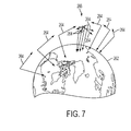
- FIG. 7 shows a global up model
- FIG. 8 shows a local up model
- FIG. 9 shows a driving up model
- FIG. 10 shows a custom up model
- FIG. 11 shows up model processing
- FIG. 12 shows custom up model processing.
- FIG. 13 shows pull mapping processing
- FIG. 14 depicts clipping
- FIG. 15 shows an effect of clipping.
- FIG. 16 shows a surface restricted field of view.
- FIG. 17 shows motion through a concave surface.
- FIG. 18 illustrates a corner hook
- FIG. 19 shows a restricted surface field of view and an obstacle field of view.
- FIG. 20 shows using the obstacle field of view.
- FIG. 21 shows obstacle processing
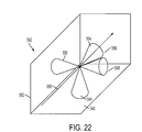
- FIG. 22 depicts multiple fields of view.
- FIG. 23 depicts system hardware.
- the present invention is a system that generates or receives a two-dimensional input, automatically pans a view of a model according to the two-dimensional input, automatically zooms the view according to the two-dimensional input, and automatically tumbles or rotates the view according to the two-dimensional input, where the panning, zooming, and tumbling are relative to a fixed point in the space of the model.
- the behavior of the invention could be considered to be like a camera that hovers above a surface or a HoverCam.
- a cylinder is a type of object or model that can be viewed with a viewing system.
- FIG. 1 shows a two-dimensional overhead view of a three-dimensional cylinder model 120 .
- Initial view 122 is a view directed to the side of the cylinder model 120 .
- Final view 124 is a view directed at the end of the cylinder model 120 .
- the initial view 122 must be zoomed out 126 , resulting in the second view 128 .
- the second view 128 must then be rotated 130 to the third view 132 .
- the third view 132 must be zoomed in 134 to arrive at the final view 124 .
- a field of influence 142 around the object specifies how strongly the surface following motion is weighted (preferably linearly interpolated) with the freeform motion.
- motion clipping is applied to smoothly transition to the motion of FIG. 1 .
- the layers of influence 142 and 144 around each object can be automatically generated by, for example, by using a spherical distance from a center of the object to set limit 142 and using the mouse-wheel is used to zoom in or out to specify a new fixed distance 144 for the surface following algorithm.
- the outer layer 142 is typically quite far from the object 140 surface and specifies a field of influence. Once a freeform camera enters this field, the surface following camera is weighted together with the freeform camera so that the camera view will be pulled towards the outer limit 146 of the orbit distance of the object 162 (see FIG. 3 ). This pulling is shown in FIG.
- the camera is fully controlled by the surface following algorithm, it preferably remains so until the user switches to another navigation method.
- the surface following camera orbit distance will always be between the inner limit 148 ( FIG. 2 ) and the outer limit 146 unless the user zooms out beyond the field of influence.
- the HoverCam system computes the desired result, which is “H-E to H-L”.
- a clipping operation e.g. moving part of the way, say 10%, toward a desired result
- B-E is the new start position S-E.
- the vector “i” may try to move off the path, a new desired vector will be computed, and the blended vector will basically move the eye back to the path represented by the black dashed line 180 .
- This blending continues until the state is reached on the right side of FIG. 3 , with the same situation existing. Starting with the eye at S-E, the user moves the mouse creating the vector “i”.
- UE-UL is orthogonal to vector “i”.
- the system finds H-E and H-L and blends to get the blended vector “B-E to B-L”.
- the three vectors in this part of the figure (U, B, and H) should really be a lot closer to each other vertically but they are spread apart somewhat for legibility and the “real” H-L would be directly below U-E on the cube wall (as the closest point to U-E) but is drawn further toward the bottom.
- FIG. 4 illustrates how the blending of the freeform camera navigation and the surface following navigation of the present invention occurs (see also FIG. 14 ).
- a mouse move creates 192 the vector “i”.
- the surface-following process is applied 194 to the motion resulting in target eye and look at points.
- motion clipping is applied 196 to produce new eye target and look at points.
- the eye point and look at point are moved 198 to these new points.
- Other types of navigational influences can also be blended using the approach discussed herein
- the present invention determines the view direction by determining the closest point on the surface of the model.
- a 3D model is typically represented as a polygonal mesh. Iterating through every polygon in the model for closest point can determine the closest point in a polygonal mesh.
- an indexing structure conventionally called a sphere-tree
- the sphere-tree is a hierarchal structure that encloses the polygons within the model (see FIG.
- FIG. 5 depicts six successive levels 212 - 222 of a sphere-tree enclosing a 3D bunny model. Notice how closely the sphere-tree represents the model at the low levels.
- the system performs (see FIG. 6 ) a top-down traversal of the sphere-tree, maintaining a list of all the spheres that satisfy the field of view (FOV) constraints that limit the view for closest point determination to be in the direction of motion so that points on the surface that are behind the current position do not cause the camera to turn backward. If a sphere fails to be within either of our FOVs, it is eliminated from the list without exploring any of its children. In this manner, the system eliminates a large majority of the polygons from the closest point analysis. As a further optimization, the systems also finds the distance from the query point to the far end of each sphere, and eliminate all the spheres further than the current minimum distance. The traversal terminates when the bottom of the sphere-tree is reached, and the result is a list of the smallest spheres from the lowest level. The polygons contained within these spheres are then subjected to conventional ray casting closest point analysis.
- FOV field of view
- a sphere tree is built 242 and a first sphere is designated.
- the system then the system examines 244 the next sphere to determine 246 if it is closer to the camera. If so, it is saved 248 .
- a determination is made 250 concerning whether more spheres at this level in the tree exist. If not, the closest saved sphere is selected 252 and the process cycles again ( 244 ). In this way a list of spheres that can include the closest point is produced.
- an up vector is typically implied relative to a view throughout the procedure.
- this can have unexpected consequences, such as when a globe is being navigated and the view traversed the top of the sphere and the sphere, such as a globe of the world, is viewed upside down.
- the model chosen to derive the up-vector at a given camera position, or given a certain camera motion may alter the overall camera metaphor.
- the present invention defines four up-models: global, local, driving, and custom.
- the up-vector 300 is view dependent and always points toward the top of the viewport (see FIG. 8 ). Therefore, moving the cursor left or right does not affect the up-vector even though the view of the globe 302 , for example, as indicated by view vectors 304 and 306 , changes. However, moving up or down causes the up-vector to be corrected so that the user never feels as though they have turned. For example, when moving over the North Pole of a globe from Canada to Russia, if Canada initially looked the right way up, Russia would appear upside-down.
- the user may wish to have the feeling that moving the input device left or right should turn the object so that moving (the device) up is always “forward”.
- moving the device up is always “forward”.
- the globe 342 as an example (see FIG. 9 )
- the horizon would rotate in the view until vertical, with the North Pole toward the left hand side of the screen.
- the up vector 344 would rotate to the direction of travel.
- This model could also be considered for a “flying” camera metaphor since it smoothly banks the camera in the left or right direction of mouse motion.
- custom up-vector fields For example, a model of an automobile 382 (see FIG. 10 ) would normally have the up-vector point from the car to high above the top of the roof. However, if a user was looking underneath the car or above the car, it may seem proper to have “up” be towards the hood. In this case, custom up-vectors 384 could be placed on the sides of an enclosing cube (see FIG. 10 ), which would be interpolated based on the current camera position, to determine the current up-vector. Preferably, the user can move to any point in space and press a hotkey to generate an up-vector at the current position and orientation. In this way, a complex up-vector field may be authored.
- the processing associated with the use of the up models discussed above starts (see FIG. 11 ) with the initialization 392 of an up vector.
- the system then applies 394 the surface following processing to obtain eye and look-at points. If the global model has been designated 396 , the up vector is set 398 to point high above the center of the scene. If the local model has been designated 400 , the up vector is set 402 as orthogonal to the look-at vector. If the model has been set 404 at the driving model, the vector is set 406 toward the input vector direction. If a custom model has been selected 408 , the vector is procedurally set 410 (see FIG. 12 ). The system then uses the vector to perform the display processing.
- one or more vector fields are defined 422 by vectors in positioned in the scene space. Ideally this is a continuous field where a vector is defined for every particular point in space, but this is procedurally costly and to reduce the computation time, discrete vectors are used to define the field.
- the system applies 424 the surface following procedure to obtain a new eye point in space and the up vector is set 426 to the nearest of the vectors positioned in the scene. The distance to the other up vectors in the scene is determined 428 . Then, for any particular point in space, the system compute 430 the target up vector by taking the weighted average of the vectors.
- the mapping of mouse motion to camera motion may either be push (egocentric) or pull (exocentric).
- a push mapping the user conceptually pushes the camera so that, for example, moving the mouse from left to right would push the camera to the right causing the model to appear to move left.
- a pull mapping the user pulls the world in the direction of motion so that dragging from left to right moves the object from left to right, achieved by moving the camera to the left.
- the invention is like the user is controlling a craft floating above the surface of an object and so one may expect the push mapping to be most effective.
- the user is typically expected to be very close to the object so that it fills most of the display.
- the cursor will typically be over the object when the mouse button is clicked.
- the system sets 442 the direction of the moved view to the direction of the selected closest ray and then moves 444 the view point along the newly set direction such that it is again the specified distance from the model.
- the system determines 446 the type of mapping that the user has set, and if the mapping is pull mapping, the direction is inverted 448 .
- a discrepancy can occur between the direction that the input device is moving and the intended camera motion in the scene. For example, for the camera motion shown in FIG. 7 , the user would move the mouse down until they reached the North Pole, but continuing to move down would do nothing. To move down the other side, the user would have to move the mouse in an upward direction. This can make the user feel as though they are “stuck” and this can be fairly confusing.
- the present invention preferably uses two up-models: one for internal calculations and one for display to the user. Internally, the local up model is used, which will move continuously across the top of the globe in a single drag motion without getting stuck, as shown in FIG. 8 .
- the “up” effect that the user sees may be any one of the four methods described above. This is accomplished by applying the local model to the camera position and orientation, followed by the application of the chosen up model. As this update is applied during every mouse-move event, the user only feels the effect of the chosen up model.
- An appropriate choice for the up-vector model by the user may be highly content dependent and may be a user preference or may be uniquely associated with each model in a scene.
- This basic algorithm discussed in the related application handles simple convex surfaces, slightly concave surfaces, and jumps across gaps or holes.
- the true closest point may be outside the current field of view (FOV) or may even be behind the camera.
- FOV current field of view
- turning the camera to immediately face the new closest point would be quite disorienting and may result in some undesirable effects. This can occur if the object has protrusions, or cavities. When gliding over a cavity, for example, the closest point can jump from one edge of the cavity to the other.
- the present invention clips the final distance traveled (of both the eye and the look-at point) to minimize these effects, slowly turning the camera to the intended position.
- the clipping looks at the vectors (see FIG. 14 ) from the old closest point to the new closest point (L 0 L 2 ) and from the old eye position to the new eye position (E 0 E 2 ). The system then clips these vectors to the length ⁇ of the input vector i generated by the mouse move. This creates the final eye to look-at vector E 3 L 3 .
- FIG. 15 shows the invention camera path while moving across the top of a torus (from left to right). Note how extra steps are generated across the hole in the torus 462 , when the closest point is on the right-hand side, to smoothly turn toward the other side of the torus 462 to continue around it.
- the camera motion shown in FIG. 15 can use an additional constraint. At the point where the camera is directly over the center of the torus, there are an infinite number of solutions when searching for the closest point. To resolve cases such as this, and to favor the user input, a restricted FOV constraint is added to only look for the closest point in the general direction of the input vector (see FIG. 16 ).
- the input vector i the input vector
- ⁇ is fixed at 45°, but could be based on the view frustum.
- P 0 is the point along the vector formed by adding i to L 0 and ensuring L 0 E 0 P 0 is 1 ⁇ 2 ⁇ . All geometry outside the triangular wedge 472 determined by E 0 L 0 P 0 , with a thickness of 2 ⁇ and a length extending infinitely away from E 0 , is disregarded during the search for the closest point to E 0 .
- the restricted FOV for searching taken together with the motion clipping handle the cases where there are multiple solutions for a closest point thereby providing the expected camera motion.
- the present invention includes a second FOV 502 that searches for obstacles in the direction of motion as depicted in FIG. 19 .
- the search for the closest point then includes both the restricted search FOV 492 and the obstacle FOV 502 .
- the closest point in either FOV will be considered to be the target point that we would like to veer towards.
- FIG. 21 illustrates how the obstacle avoidance process of the present invention occurs.
- the user moves the mouse and the input vector “i” is created 522 .
- FOV restricted field of view
- a new closest point is found 524 .
- the obstacle FOV is then used to find 526 the closest point of any obstacle. If an obstacle is detected 528 , the eye point is moved 530 and motion clipping is then applied 531 .
- a single object FOV and a single obstacle FOV have been discussed for controlling the camera path.
- additional obstacle FOVs may be used, such as an FOV that would detect a protrusion coming from behind the camera.
- Other constraints may be added such as a “distance from floor” constraint used for an architectural walk-through.
- the view of the scene by the camera is of the object when the camera is performing surface following.
- the view by the camera need not be of the object or surface that is being followed. For example, in architectural walk-through of a virtual room 542 (see FIG.
- the surface-following FOV 544 can maintain the camera a predetermined distance off a floor 546 of the virtual building
- obstacle FOVs 548 and 550 pointing to the sides can prevent the camera from colliding with side walls, such as side wall 552
- a direction of travel FOV 554 can prevent collision with obstacles in the direction of travel 556 while the view 558 of the camera can be of the interior of the building, such as a view parallel with the floor and along the direction of travel.
- the view could also be controllable by the user during navigation, such as by allowing the user to point the camera up at the ceiling of the room.
- the side FOVs 548 and 550 allow easy navigation down a center of a hallway.
- the present invention is included in a system 580 , such as depicted in FIG. 23 , which includes a display 582 upon which an output of the present invention may be displayed.
- a computer 584 preferably of high performance workstation type, performs the processes described herein and an input device 586 , such as a mouse or stylus with pad, is used to control functionality described herein.
- the system 580 also includes storage (not shown), such as disc storage and RAM in which the processes of the present invention can be stored and on which the processes can be distributed.
- the processes can also be distributed via a network, such as the Internet.
- the system also includes permanent or removable storage, such as magnetic and optical discs, RAM, ROM, etc. on which the process and data structures of the present invention can be stored and distributed.
- the processes can also be distributed via, for example, downloading over a network such as the Internet.
- the present invention has been described with respect to computationally finding a closest point. It is possible to use other methods such as a hardware-generated z-buffer, may be used to find the closest point. A smoothing pass can also be performed on the eye and look-at points to further smooth the resulting camera motion.
- the system can include other types of interactions, for example, the user may be allowed to transiently engage a “look-around” mode, switching back to HoverCam after a drag operation.
- a compact disc is included herewith and incorporated by reference herein having thereon a video that shows features of the present invention and can be played using Windows Media Player TM.
Abstract
Description
Claims (2)
Priority Applications (1)
| Application Number | Priority Date | Filing Date | Title |
|---|---|---|---|
| US11/390,306 US8044953B2 (en) | 2002-06-28 | 2006-03-28 | System for interactive 3D navigation for proximal object inspection |
Applications Claiming Priority (2)
| Application Number | Priority Date | Filing Date | Title |
|---|---|---|---|
| US10/183,432 US7042449B2 (en) | 2002-06-28 | 2002-06-28 | Push-tumble three dimensional navigation system |
| US11/390,306 US8044953B2 (en) | 2002-06-28 | 2006-03-28 | System for interactive 3D navigation for proximal object inspection |
Related Parent Applications (1)
| Application Number | Title | Priority Date | Filing Date |
|---|---|---|---|
| US10/183,432 Continuation-In-Part US7042449B2 (en) | 2002-06-28 | 2002-06-28 | Push-tumble three dimensional navigation system |
Publications (2)
| Publication Number | Publication Date |
|---|---|
| US20060227134A1 US20060227134A1 (en) | 2006-10-12 |
| US8044953B2 true US8044953B2 (en) | 2011-10-25 |
Family
ID=46324169
Family Applications (1)
| Application Number | Title | Priority Date | Filing Date |
|---|---|---|---|
| US11/390,306 Active 2025-01-18 US8044953B2 (en) | 2002-06-28 | 2006-03-28 | System for interactive 3D navigation for proximal object inspection |
Country Status (1)
| Country | Link |
|---|---|
| US (1) | US8044953B2 (en) |
Cited By (5)
| Publication number | Priority date | Publication date | Assignee | Title |
|---|---|---|---|---|
| WO2014039259A1 (en) * | 2012-09-04 | 2014-03-13 | Google Inc. | User interface for orienting a camera view toward surfaces in a 3d map and devices incorporating the user interface |
| US9361665B2 (en) | 2013-11-27 | 2016-06-07 | Google Inc. | Methods and systems for viewing a three-dimensional (3D) virtual object |
| WO2016179825A1 (en) * | 2015-05-14 | 2016-11-17 | 中国科学院深圳先进技术研究院 | Navigation method based on three-dimensional scene |
| US10891780B2 (en) | 2013-11-27 | 2021-01-12 | Google Llc | Methods and systems for viewing a three-dimensional (3D) virtual object |
| DE112019007695T5 (en) | 2019-10-07 | 2022-05-25 | Mitsubishi Electric Corporation | VIRTUAL CAMERA CONTROL DEVICE, VIRTUAL CAMERA CONTROL METHOD AND VIRTUAL CAMERA CONTROL PROGRAM |
Families Citing this family (15)
| Publication number | Priority date | Publication date | Assignee | Title |
|---|---|---|---|---|
| US20090259976A1 (en) * | 2008-04-14 | 2009-10-15 | Google Inc. | Swoop Navigation |
| US8269767B2 (en) * | 2009-02-03 | 2012-09-18 | Autodesk, Inc. | Multiscale three-dimensional reference grid |
| US8577518B2 (en) * | 2009-05-27 | 2013-11-05 | American Aerospace Advisors, Inc. | Airborne right of way autonomous imager |
| US8626434B1 (en) | 2012-03-01 | 2014-01-07 | Google Inc. | Automatic adjustment of a camera view for a three-dimensional navigation system |
| US9786097B2 (en) * | 2012-06-22 | 2017-10-10 | Matterport, Inc. | Multi-modal method for interacting with 3D models |
| US10163261B2 (en) | 2014-03-19 | 2018-12-25 | Matterport, Inc. | Selecting two-dimensional imagery data for display within a three-dimensional model |
| US10139985B2 (en) | 2012-06-22 | 2018-11-27 | Matterport, Inc. | Defining, displaying and interacting with tags in a three-dimensional model |
| US10127722B2 (en) | 2015-06-30 | 2018-11-13 | Matterport, Inc. | Mobile capture visualization incorporating three-dimensional and two-dimensional imagery |
| EP2872980B1 (en) * | 2012-07-15 | 2018-10-17 | Apple Inc. | Disambiguation of multitouch gesture recognition for 3d interaction |
| RU2608870C2 (en) * | 2014-10-30 | 2017-01-25 | Общество С Ограниченной Ответственностью "Яндекс" | Method (versions) and electronic device (versions) for determination of point location relative to the first polygon in multidimensional space |
| US11474660B2 (en) * | 2017-08-11 | 2022-10-18 | Autodesk, Inc. | Techniques for transitioning from a first navigation scheme to a second navigation scheme |
| US11010014B2 (en) | 2017-08-11 | 2021-05-18 | Autodesk, Inc. | Techniques for transitioning from a first navigation scheme to a second navigation scheme |
| EP4305847A1 (en) * | 2021-03-10 | 2024-01-17 | QUALCOMM Incorporated | Camera control data for virtual camera in virtual interactive scene defined by streamed media data |
| KR20230155445A (en) * | 2021-03-10 | 2023-11-10 | 퀄컴 인코포레이티드 | Object collision data for virtual cameras in a virtual interactive scene defined by streamed media data |
| US20220292770A1 (en) * | 2021-03-10 | 2022-09-15 | Qualcomm Incorporated | Object collision data for virtual camera in virtual interactive scene defined by streamed media data |
Citations (17)
| Publication number | Priority date | Publication date | Assignee | Title |
|---|---|---|---|---|
| US5276785A (en) * | 1990-08-02 | 1994-01-04 | Xerox Corporation | Moving viewpoint with respect to a target in a three-dimensional workspace |
| US5943056A (en) * | 1995-07-11 | 1999-08-24 | Fujitsu Ltd. | Interference checking method |
| US6064389A (en) * | 1997-05-27 | 2000-05-16 | International Business Machines Corporation | Distance dependent selective activation of three-dimensional objects in three-dimensional workspace interactive displays |
| US6097393A (en) * | 1996-09-03 | 2000-08-01 | The Takshele Corporation | Computer-executed, three-dimensional graphical resource management process and system |
| US6144375A (en) * | 1998-08-14 | 2000-11-07 | Praja Inc. | Multi-perspective viewer for content-based interactivity |
| US6222557B1 (en) * | 1998-06-26 | 2001-04-24 | Visual Insights, Inc. | Navigation system and method for viewing a 3D data landscape |
| US6377256B1 (en) * | 1998-12-24 | 2002-04-23 | Intel Corporation | Assisted camera orientation and positioning during object manipulation in a three-dimensional scene |
| US20020050988A1 (en) * | 2000-03-28 | 2002-05-02 | Michael Petrov | System and method of three-dimensional image capture and modeling |
| US20020075258A1 (en) * | 1999-05-12 | 2002-06-20 | Imove Inc. | Camera system with high resolution image inside a wide angle view |
| US6640185B2 (en) * | 2001-07-21 | 2003-10-28 | Alpine Electronics, Inc. | Display method and apparatus for navigation system |
| US20040189802A1 (en) * | 2001-07-27 | 2004-09-30 | Mark Flannery | Control system for allowing an operator to proportionally control a work piece |
| US20040210852A1 (en) * | 2000-04-28 | 2004-10-21 | Silicon Graphics, Inc. | System for dynamically mapping input device movement as a user's viewpoint changes |
| US20060080604A1 (en) * | 1997-04-14 | 2006-04-13 | Anderson Thomas G | Navigation and viewing in a multidimensional space |
| US7038712B1 (en) * | 2002-04-18 | 2006-05-02 | Hewlett-Packard Development Company, L.P. | Geometric and photometric calibration of cameras |
| US7058239B2 (en) * | 2001-10-29 | 2006-06-06 | Eyesee360, Inc. | System and method for panoramic imaging |
| US7123777B2 (en) * | 2001-09-27 | 2006-10-17 | Eyesee360, Inc. | System and method for panoramic imaging |
| US7589732B2 (en) * | 2002-11-05 | 2009-09-15 | Autodesk, Inc. | System and method of integrated spatial and temporal navigation |
-
2006
- 2006-03-28 US US11/390,306 patent/US8044953B2/en active Active
Patent Citations (17)
| Publication number | Priority date | Publication date | Assignee | Title |
|---|---|---|---|---|
| US5276785A (en) * | 1990-08-02 | 1994-01-04 | Xerox Corporation | Moving viewpoint with respect to a target in a three-dimensional workspace |
| US5943056A (en) * | 1995-07-11 | 1999-08-24 | Fujitsu Ltd. | Interference checking method |
| US6097393A (en) * | 1996-09-03 | 2000-08-01 | The Takshele Corporation | Computer-executed, three-dimensional graphical resource management process and system |
| US20060080604A1 (en) * | 1997-04-14 | 2006-04-13 | Anderson Thomas G | Navigation and viewing in a multidimensional space |
| US6064389A (en) * | 1997-05-27 | 2000-05-16 | International Business Machines Corporation | Distance dependent selective activation of three-dimensional objects in three-dimensional workspace interactive displays |
| US6222557B1 (en) * | 1998-06-26 | 2001-04-24 | Visual Insights, Inc. | Navigation system and method for viewing a 3D data landscape |
| US6144375A (en) * | 1998-08-14 | 2000-11-07 | Praja Inc. | Multi-perspective viewer for content-based interactivity |
| US6377256B1 (en) * | 1998-12-24 | 2002-04-23 | Intel Corporation | Assisted camera orientation and positioning during object manipulation in a three-dimensional scene |
| US20020075258A1 (en) * | 1999-05-12 | 2002-06-20 | Imove Inc. | Camera system with high resolution image inside a wide angle view |
| US20020050988A1 (en) * | 2000-03-28 | 2002-05-02 | Michael Petrov | System and method of three-dimensional image capture and modeling |
| US20040210852A1 (en) * | 2000-04-28 | 2004-10-21 | Silicon Graphics, Inc. | System for dynamically mapping input device movement as a user's viewpoint changes |
| US6640185B2 (en) * | 2001-07-21 | 2003-10-28 | Alpine Electronics, Inc. | Display method and apparatus for navigation system |
| US20040189802A1 (en) * | 2001-07-27 | 2004-09-30 | Mark Flannery | Control system for allowing an operator to proportionally control a work piece |
| US7123777B2 (en) * | 2001-09-27 | 2006-10-17 | Eyesee360, Inc. | System and method for panoramic imaging |
| US7058239B2 (en) * | 2001-10-29 | 2006-06-06 | Eyesee360, Inc. | System and method for panoramic imaging |
| US7038712B1 (en) * | 2002-04-18 | 2006-05-02 | Hewlett-Packard Development Company, L.P. | Geometric and photometric calibration of cameras |
| US7589732B2 (en) * | 2002-11-05 | 2009-09-15 | Autodesk, Inc. | System and method of integrated spatial and temporal navigation |
Non-Patent Citations (1)
| Title |
|---|
| A. Khan, et al., HoverCam: Interactive 3D Navigation for Promixal Object Inspection, Proceedings of the 2005 symposium on Interactive 3D Graphics and Games; Apr. 2005 pp. 1-8. |
Cited By (8)
| Publication number | Priority date | Publication date | Assignee | Title |
|---|---|---|---|---|
| WO2014039259A1 (en) * | 2012-09-04 | 2014-03-13 | Google Inc. | User interface for orienting a camera view toward surfaces in a 3d map and devices incorporating the user interface |
| US9361665B2 (en) | 2013-11-27 | 2016-06-07 | Google Inc. | Methods and systems for viewing a three-dimensional (3D) virtual object |
| US10460510B2 (en) | 2013-11-27 | 2019-10-29 | Google Llc | Methods and systems for viewing a three-dimensional (3D) virtual object |
| US10891780B2 (en) | 2013-11-27 | 2021-01-12 | Google Llc | Methods and systems for viewing a three-dimensional (3D) virtual object |
| WO2016179825A1 (en) * | 2015-05-14 | 2016-11-17 | 中国科学院深圳先进技术研究院 | Navigation method based on three-dimensional scene |
| US20170153116A1 (en) * | 2015-05-14 | 2017-06-01 | Shenzhen Institutes Of Advanced Technology Chinese Academy Of Sciences | Navigation technology in three-dimensional scenes |
| US10066956B2 (en) * | 2015-05-14 | 2018-09-04 | Shenzhen Institutes Of Advanced Technology Chinese Academy Of Sciences | Navigation technology in three-dimensional scenes |
| DE112019007695T5 (en) | 2019-10-07 | 2022-05-25 | Mitsubishi Electric Corporation | VIRTUAL CAMERA CONTROL DEVICE, VIRTUAL CAMERA CONTROL METHOD AND VIRTUAL CAMERA CONTROL PROGRAM |
Also Published As
| Publication number | Publication date |
|---|---|
| US20060227134A1 (en) | 2006-10-12 |
Similar Documents
| Publication | Publication Date | Title |
|---|---|---|
| US8044953B2 (en) | System for interactive 3D navigation for proximal object inspection | |
| Khan et al. | Hovercam: interactive 3d navigation for proximal object inspection | |
| US7148892B2 (en) | 3D navigation techniques | |
| Mine | Virtual environment interaction techniques | |
| Drucker et al. | Intelligent camera control in a virtual environment | |
| Salomon et al. | Interactive navigation in complex environments using path planning | |
| JP7092445B2 (en) | Methods and systems that provide remote robotic control | |
| McCrae et al. | Multiscale 3D navigation | |
| JP7311172B2 (en) | Method and system for providing remote robotic control | |
| Nielsen et al. | Ecological interfaces for improving mobile robot teleoperation | |
| Nieuwenhuisen et al. | Motion planning for camera movements | |
| US5513303A (en) | Moving an object in a three-dimensional workspace | |
| US6556206B1 (en) | Automated viewpoint selection for 3D scenes | |
| Nieuwenhuisen et al. | High quality navigation in computer games | |
| US6184867B1 (en) | Input for three dimensional navigation using two joysticks | |
| WO2009148610A2 (en) | Responsive control method and system for a telepresence robot | |
| Bares et al. | Cinematographic user models for automated realtime camera control in dynamic 3D environments | |
| US6222554B1 (en) | Navigation in three-dimensional workspace interactive displays having virtual force fields associated with selected objects | |
| Buchholz et al. | Smart and physically-based navigation in 3D geovirtual environments | |
| Wojciechowski | Camera navigation support in a virtual environment | |
| KR101633890B1 (en) | Apparatus and method for controlling navigation based on collision prediction | |
| Fuhrmann et al. | Strolling through cyberspace with your hands in your pockets: Head directed navigation in virtual environments | |
| Srinivasan et al. | Controllable real-time locomotion using mobility maps | |
| Hilsendeger et al. | Navigation in virtual reality with the wii balance board | |
| Ropinski et al. | A constrained road-based VR navigation technique for travelling in 3D city models |
Legal Events
| Date | Code | Title | Description |
|---|---|---|---|
| AS | Assignment |
Owner name: AUTODESK, INC., CALIFORNIA Free format text: ASSIGNMENT OF ASSIGNORS INTEREST;ASSIGNORS:KHAN, AZAM;KOMALO, BENYAMIN;SIGNING DATES FROM 20060324 TO 20060327;REEL/FRAME:017686/0193 Owner name: AUTODESK, INC., CALIFORNIA Free format text: ASSIGNMENT OF ASSIGNORS INTEREST;ASSIGNORS:KHAN, AZAM;KOMALO, BENYAMIN;REEL/FRAME:017686/0193;SIGNING DATES FROM 20060324 TO 20060327 |
|
| AS | Assignment |
Owner name: AUTODESK, INC.,CALIFORNIA Free format text: ASSIGNMENT OF ASSIGNORS INTEREST;ASSIGNOR:ALIAS SYSTEMS CORPORATION;REEL/FRAME:018375/0466 Effective date: 20060125 Owner name: AUTODESK, INC., CALIFORNIA Free format text: ASSIGNMENT OF ASSIGNORS INTEREST;ASSIGNOR:ALIAS SYSTEMS CORPORATION;REEL/FRAME:018375/0466 Effective date: 20060125 |
|
| STCF | Information on status: patent grant |
Free format text: PATENTED CASE |
|
| FPAY | Fee payment |
Year of fee payment: 4 |
|
| MAFP | Maintenance fee payment |
Free format text: PAYMENT OF MAINTENANCE FEE, 8TH YEAR, LARGE ENTITY (ORIGINAL EVENT CODE: M1552); ENTITY STATUS OF PATENT OWNER: LARGE ENTITY Year of fee payment: 8 |
|
| MAFP | Maintenance fee payment |
Free format text: PAYMENT OF MAINTENANCE FEE, 12TH YEAR, LARGE ENTITY (ORIGINAL EVENT CODE: M1553); ENTITY STATUS OF PATENT OWNER: LARGE ENTITY Year of fee payment: 12 |