US8045634B2 - Methods and apparatus for use in reducing residual phase error in OFDM communication signals - Google Patents
Methods and apparatus for use in reducing residual phase error in OFDM communication signals Download PDFInfo
- Publication number
- US8045634B2 US8045634B2 US12/466,737 US46673709A US8045634B2 US 8045634 B2 US8045634 B2 US 8045634B2 US 46673709 A US46673709 A US 46673709A US 8045634 B2 US8045634 B2 US 8045634B2
- Authority
- US
- United States
- Prior art keywords
- channel
- received signal
- phases
- phase error
- estimate
- Prior art date
- Legal status (The legal status is an assumption and is not a legal conclusion. Google has not performed a legal analysis and makes no representation as to the accuracy of the status listed.)
- Expired - Fee Related
Links
- 238000000034 method Methods 0.000 title claims abstract description 79
- 238000004891 communication Methods 0.000 title claims abstract description 40
- 230000008569 process Effects 0.000 description 44
- 238000005562 fading Methods 0.000 description 18
- 230000000694 effects Effects 0.000 description 14
- 238000012937 correction Methods 0.000 description 13
- 230000005540 biological transmission Effects 0.000 description 12
- 238000010586 diagram Methods 0.000 description 9
- 238000012545 processing Methods 0.000 description 9
- 238000012546 transfer Methods 0.000 description 6
- 238000012935 Averaging Methods 0.000 description 5
- 238000006243 chemical reaction Methods 0.000 description 5
- 230000006735 deficit Effects 0.000 description 4
- 238000004148 unit process Methods 0.000 description 4
- 229920000535 Tan II Polymers 0.000 description 2
- 239000000654 additive Substances 0.000 description 2
- 230000000996 additive effect Effects 0.000 description 2
- 238000013459 approach Methods 0.000 description 2
- 230000001427 coherent effect Effects 0.000 description 2
- 238000001914 filtration Methods 0.000 description 2
- 238000013507 mapping Methods 0.000 description 2
- 238000012986 modification Methods 0.000 description 2
- 230000004048 modification Effects 0.000 description 2
- 230000010363 phase shift Effects 0.000 description 2
- 101100514842 Xenopus laevis mtus1 gene Proteins 0.000 description 1
- 230000008901 benefit Effects 0.000 description 1
- 239000000969 carrier Substances 0.000 description 1
- 230000001413 cellular effect Effects 0.000 description 1
- 230000008859 change Effects 0.000 description 1
- 238000007796 conventional method Methods 0.000 description 1
- 230000007812 deficiency Effects 0.000 description 1
- 238000001514 detection method Methods 0.000 description 1
- 238000003780 insertion Methods 0.000 description 1
- 230000037431 insertion Effects 0.000 description 1
- 230000009467 reduction Effects 0.000 description 1
- 238000005070 sampling Methods 0.000 description 1
- 230000003595 spectral effect Effects 0.000 description 1
Images


Classifications
-
- H—ELECTRICITY
- H04—ELECTRIC COMMUNICATION TECHNIQUE
- H04L—TRANSMISSION OF DIGITAL INFORMATION, e.g. TELEGRAPHIC COMMUNICATION
- H04L27/00—Modulated-carrier systems
- H04L27/26—Systems using multi-frequency codes
- H04L27/2601—Multicarrier modulation systems
- H04L27/2647—Arrangements specific to the receiver only
- H04L27/2655—Synchronisation arrangements
- H04L27/2689—Link with other circuits, i.e. special connections between synchronisation arrangements and other circuits for achieving synchronisation
- H04L27/2695—Link with other circuits, i.e. special connections between synchronisation arrangements and other circuits for achieving synchronisation with channel estimation, e.g. determination of delay spread, derivative or peak tracking
-
- H—ELECTRICITY
- H04—ELECTRIC COMMUNICATION TECHNIQUE
- H04L—TRANSMISSION OF DIGITAL INFORMATION, e.g. TELEGRAPHIC COMMUNICATION
- H04L27/00—Modulated-carrier systems
- H04L27/26—Systems using multi-frequency codes
- H04L27/2601—Multicarrier modulation systems
- H04L27/2647—Arrangements specific to the receiver only
- H04L27/2655—Synchronisation arrangements
- H04L27/2657—Carrier synchronisation
- H04L27/266—Fine or fractional frequency offset determination and synchronisation
-
- H—ELECTRICITY
- H04—ELECTRIC COMMUNICATION TECHNIQUE
- H04L—TRANSMISSION OF DIGITAL INFORMATION, e.g. TELEGRAPHIC COMMUNICATION
- H04L27/00—Modulated-carrier systems
- H04L27/26—Systems using multi-frequency codes
- H04L27/2601—Multicarrier modulation systems
- H04L27/2647—Arrangements specific to the receiver only
- H04L27/2655—Synchronisation arrangements
- H04L27/2668—Details of algorithms
- H04L27/2673—Details of algorithms characterised by synchronisation parameters
- H04L27/2676—Blind, i.e. without using known symbols
- H04L27/2679—Decision-aided
Definitions
- the present invention relates generally to the field of radio communication receivers. More particularly, the present invention relates to the field of reducing residual phase error (RPE) of orthogonal frequency division multiplexing (OFDM) signals in OFDM communication receivers.
- RPE residual phase error
- An increasing need for broadband mobile/fixed wireless communications services has motivated researchers and radio engineers to search for a variety of feasible radio airlink interface techniques for such wireless communication systems.
- An airlink interface technique based on the Orthogonal Frequency Division Multiplexing (OFDM) modulation is considered an attractive candidate for a broadband wireless transmission system due to its spectral efficiency, its robustness in different multipath propagation environments and its ability to combat intersymbol interference (ISI).
- OFDM Orthogonal Frequency Division Multiplexing
- OFDM is a multi-carrier modulation method. It divides an entire frequency band into many, say N, subchannels or frequency tones, and each subchannel is modulated with a constellation symbol to be transmitted. In its application as a multiple access method for a point-to-multipoint wireless communication system, OFDM arranges these total N subchannels as follows. M adjacent subchannels are grouped together (where M ⁇ N) without overlapping between adjacent groups. Each mobile user is assigned a cluster of M subchannels when it needs to transmit information data between its serving base station and its terminal.
- each cluster of M subchannels assigned to an individual user one or more subchannels may be used to transmit pilot signals and are called “pilot subchannels.”
- the rest of the subchannels bear information data and are called “information subchannels.”
- An OFDM-based wireless system is very sensitive to channel phase errors and the phase noise of the receiver local oscillator (LO). Therefore, an effective fading channel estimation and the transform domain channel compensation become necessary to restore OFDM signal orthogonality, to correct phase error, and to conduct coherent demodulation in the receiver.
- LO receiver local oscillator
- an OFDM data block is the block of M constellation symbols to be transmitted within a TDMA time slot.
- channel estimation and transform domain channel compensation must be performed in each individual data block with the pilot symbols inserted in the given data block.
- the interval between two OFDM data blocks may be on the order of 3-5 milliseconds. In such a relatively long time period, the phase noise effect of the receiver LO may change significantly.
- Co-channel interference due to any frequency reuse pattern, multipath fading, and additive white Gaussian noise (AWGN) are primary constraints to an acceptable performance in a cellular/wireless communication system.
- intercarrier interference (ICI) due to channel variation and phase noise always exists in an OFDM-based wireless system.
- ICI intercarrier interference
- the pilot symbols as well as the information symbols are corrupted by co-channel-interference, intercarrier-interference, noise, and other channel impairments. All of these impairments in the received pilot signals significantly affect the accuracy of the channel estimation.
- a residual phase error (RPE) is the phase error that remains after the received constellation symbols are compensated based on an inaccurate channel estimation.
- the accuracy of the channel estimation may be improved by either increasing the number of pilot signals and/or increasing their transmission power.
- using a larger number of pilot symbols results in a higher transmission overhead and hence a lower system capacity.
- a larger transmission power for pilot sub-channels results in larger ICIs for information-bearing tones and hence causes implementation difficulties. Accordingly, there is an existing need to reduce the residual phase error in OFDM communication signals without the deficiencies of the prior art.
- a pilot symbol-aided channel estimation scheme is employed in a wireless OFDM system.
- the new technique takes advantage of OFDM-based systems where a block of constellation symbols are transmitted simultaneously and all of these symbols experience the same channel fading. Broadly, the technique utilizes a block of detected symbols, based on their hard-decisions as the real transmitted symbols, to estimate and remove the residual phase error after the channel has been compensated.
- an apparatus in at least one embodiment of the invention, includes a residual phase error estimator configured to estimate a residual phase error at least partially based on a plurality of phases of a first channel-compensated received signal and a plurality of phases of a sliced version of the first channel-compensated received signal.
- the residual phase error estimator is configured to correct a channel estimate at least partially based on the residual phase error estimate to thereby generate a corrected channel estimate.
- the apparatus includes a channel compensator configured to generate a second channel-compensated received signal at least partially based on a received signal and the corrected channel estimate.
- a method for use in orthogonal frequency division multiplexed (OFDM) communications includes estimating a residual phase error at least partially based on a plurality of phases of a first channel-compensated received signal and a plurality of phases of a sliced version of the first channel-compensated received signal to thereby generate a residual phase error estimate.
- the method includes generating a second channel-compensated received signal at least partially based on the received signal and a corrected channel estimate.
- the corrected channel estimate is at least partially based on the residual phase error estimate.
- FIG. 1 is a diagram of a wireless communication system, such as a fixed wireless system utilizing orthogonal frequency division multiplexing (OFDM) communication techniques, which includes one or more base units and one or more remote units.
- OFDM orthogonal frequency division multiplexing
- FIG. 2 is a general block diagram of processing components for an OFDM-based wireless communication system which utilizes pilot-based signal correction.
- FIG. 3 is a block diagram of more specific processing components of the remote unit of FIG. 2 related to channel compensation using pilot tone symbols.
- FIG. 4 is a graph showing relationships between fading channel gain, its estimation, and the estimation error for the channel compensation described in relation to FIG. 3 .
- FIG. 5 is a block diagram of a first embodiment of components utilized in the remote unit of FIG. 2 which are operative to reduce residual phase error in OFDM communication signals.
- FIG. 6 is a block diagram of a second embodiment of components utilized in the remote unit of FIG. 2 which are operative to reduce the residual phase error in OFDM communication signals.
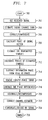
- FIG. 7 is a flowchart describing a method for use in reducing the residual phase error in OFDM communication signals.
- FIG. 8 is a timing diagram showing radio frequency (RF) OFDM signals and OFDM packets in the wireless communication system.
- RF radio frequency
- FIG. 9 is an illustrative representation of the relationship between time slots and time frames utilized in the wireless communication system.
- FIG. 10 is an illustrative representation of the frequency layout of traffic and pilot tones utilized in the wireless communication system.
- FIG. 1 is an illustrative representation of a wireless communication system 100 which utilizes orthogonal frequency division multiplexing (OFDM) or OFDM-like communication methodologies.
- Wireless communication system 100 includes at least one base unit 106 having one or more antennas 108 , and a plurality of remote units 102 (“RUs” or “transceiver units”), such as remote unit 104 .
- Base unit 106 and remote units 102 communicate via radio frequency (RF) signals, such as RF signals 110 between base unit 106 and remote unit 104 .
- RF radio frequency
- Wireless communication system 100 can make use of a number of different communication techniques, such as frequency division multiple access (FDMA), time division multiple access (TDMA), or time division duplex (TDD).
- FDMA frequency division multiple access
- TDMA time division multiple access
- TDD time division duplex
- wireless communication system 100 is a “fixed wireless system” (FWS) or Digital Broadband service, where base unit 106 provides telephone and high-speed data communication to each one of a number of fixed-location subscribers equipped with an RU.
- the RF OFDM communications signals are modulated using 16 quadrature amplitude modulation (QAM), or quadrature phase shift keying (QPSK).
- QAM quadrature amplitude modulation
- QPSK quadrature phase shift keying
- the wireless system employs a frequency division duplex (FDD) technique to implement the downlink (base unit to remote unit) and uplink (remote unit to base unit) transmissions. Since uplink and downlink transmissions are symmetric, only downlink transmission will be described herein.
- FDD frequency division duplex
- each base unit of the wireless communication system transmits a plurality of OFDM packets 802 , such as an OFDM packet 804 , to a corresponding remote unit.
- a new OFDM packet is transmitted once every predetermined time period.
- Each predetermined time period is associated with a time slot, such as a time slot 906 of FIG. 9 .
- a plurality of consecutive time slots 904 corresponds to a time frame 902 .
- each time slot has a duration of 375 microseconds
- each OFDM packet is 320 microseconds in length
- each time frame corresponds to 8 time slots for a duration of 3 milliseconds.
- Each base unit transmits “traffic tones” and “pilot tones” to a corresponding remote unit. Traffic tones are utilized for the communication of voice and/or data, whereas pilot tones are utilized for channel compensation.
- each remote unit samples the OFDM waveforms at a sampling rate to generate time domain samples, and converts the time domain samples into frequency domain signals (e.g., traffic or pilot tones).
- FIG. 10 an illustrative representation of the frequency layout of traffic and pilot tones utilized in the wireless communication system is shown.
- Data symbols on traffic tones (“Tch”) of a particular frequency slot are transmitted in a particular time slot.
- data symbols on traffic tones 1002 of frequency slot 1006 are transmitted in one particular time slot.
- each frequency slot has eighteen traffic tones. One or more of these tones, such as a tone 1004 , are used as pilot tones for channel estimation and compensation.
- Each remote unit is assigned a traffic channel that is defined by a unique time and frequency slot combination.
- One remote unit may be assigned to receive information within, for example, each time slot to (e.g., time slot 906 of FIG. 9 ) at frequency slot f 5 (e.g., a frequency slot 1002 of FIG. 10 ), while another remote unit may be assigned to receive information within, for example, each time slot t 6 at frequency slot f 2 .
- Each remote unit in the wireless communication system utilizes the pilot tone within its assigned time slot to perform channel compensation and the methods described herein. So, if a single pilot tone is provided within each time slot, then each remote unit utilizes a single pilot tone in each time frame for channel compensation.
- FIG. 2 shows a general block diagram 200 of an OFDM-based radio communication system which utilizes pilot-based signal correction.
- Diagram 200 is divided into base unit processes 202 for a base unit, remote unit processes 204 for a remote unit, and an airlink 206 .
- base unit processes 202 binary information data is encoded using a channel encoding process 208 and mapped into M ⁇ 1 multi-amplitude multi-phase constellation symbols using a signal mapping process 210 .
- S/P serial-to-parallel conversion process
- one pilot symbol is inserted in the information data sequence for a “user i” before its data is multiplexed with other users' data. There are total M symbols for user i.
- a data sequence of length N from K users is converted into N parallel symbols, which are fed into an Inverse Fast Fourier Transform (IFFT) 214 from a tone mapping process 214 .
- IFFT 214 modulates these symbols on N subcarriers and sums them.
- a guard interval is added by a guard interval insertion process 218 and a parallel-to-serial conversion process 220 (“P/S”) is applied.
- D/A digital-to-analog
- the signals over airlink 206 are received and processed by remote unit processes 204 .
- lowpass filtering and analog-to-digital (A/D) conversion are applied using an A/D converter and lowpass filter 224 .
- a serial-to-parallel conversion process 226 (“S/P”) converts the signals from serial to parallel and a guard interval removal process 228 removes the existing guard interval.
- Data for user i is demultiplexed from the output of a Fast Fourier Transform (FFT) 230 , where tone demapping is performed by a tone demapping process 232 .
- Pilot-based signal correction is performed using a channel estimation process 234 and a signal correction process 236 .
- M ⁇ 1 information-bearing symbols are demapped and decoded into binary data by a signal demapping process 240 and a channel decoding process 242 , respectively.
- FFT Fast Fourier Transform
- the selection of M is based on the data rate and fading environment: It is typically chosen so that the traffic transmission channel is frequency-flat and no channel equalizer is necessary. Therefore, the transmission channel of M sub-channels is assumed as a frequency-flat channel.
- FIG. 3 shows a receiver processing portion 300 of a remote unit in wireless communication system 100 of FIG. 1 .
- Receiver processing portion 300 includes a channel estimation process 302 and a channel compensation process 304 .
- the following detailed signal model analysis is based on receiver processing portion 300 shown in FIG. 3 .
- a block of M encoded and modulated constellation symbols to be transmitted, denoted as X(n), is
- X ⁇ ( n ) [ S 1 ⁇ ( n ) S 2 ⁇ ( n ) ⁇ S M - 1 ⁇ ( n ) S P ⁇ ( n ) ] ( Eq . ⁇ 1 )
- n is the index for the nth block of user data and each block consists of M symbols, one of them is the pilot symbol
- S P (n) is the pilot symbol inserted in the nth block of user data
- the transmission channel for an individual user is considered a frequency-flat fading channel and its transfer function is modeled as a complex coefficient denoted as ⁇ (n). This is because the bandwidth which M subchannels spans is much less than the fading channel coherent bandwidth.
- the receiver local oscillator (LO) phase noise has two effects on the OFDM signal.
- One effect is the common phase errors that are the same for all subchannels.
- the common phase error is, in fact, a phase shift for each subchannel and can be incorporated with fading channel phase.
- the second effect is a noise-like intercarrier interference (ICI). It can be treated as noise, and will therefore not be considered in the remaining description.
- ICI noise-like intercarrier interference
- the received signal may be represented as
- ⁇ is the true fading channel gain or transfer function.
- the channel estimation error, ⁇ N due to co-channel interference (CCI), AWGN, and ICI is
- MSE mean-square-error
- the second item, S Ni is an AWGN variable.
- the second effect is that the constellation of the transmitted symbols is rotated by an angle of ⁇ N .
- the channel estimation error is very small, then the residual angle will become small too.
- MSE mean-square-error
- MRC maximum ratio combining
- the objective is to reduce the residual phase error in received constellation signals due to the pilot-based channel estimation.
- the channel phase estimation error must first be estimated and then removed from the received signals. What is described herein is a novel technique for estimating the residual phase error, ⁇ N , and utilizing it for such correction.
- ⁇ i represents the effect of the second item in Eq. 22 on the amplitude of the ith transmitted symbol, S i , and is a random variable and is confined within the following range:
- the first objective is to estimate the residual phase error, ⁇ N , from phases of the received signals in Eq. 26. It is found that the residual phase error, ⁇ N , is a constant for all M ⁇ 1 received symbol signals.
- ⁇ N it is important to know the information phase, ⁇ i , for each transmitted symbol, S i .
- a hard-decision slicer is employed to find each transmitted symbol with a fair accuracy based on the corresponding received constellation signal.
- the output of the slicer is the estimate of the corresponding transmitted symbol at the transmitter end. Due to noise, co-channel interference, and channel estimation errors, the output of the slicer is given as
- S i , and S j are transmitting constellation symbols.
- the corresponding information phase estimate, ⁇ is given as
- the symbol error is due to channel impairments and channel estimation errors. If the channel is very bad, the symbol error rate will be very high and therefore the slicer may not be reliable. In most situations, however, the symbol error rate is acceptable. For example, the symbol error rate is likely to be less than 5*10 ⁇ 2 when the slicer is employed in the embodiment described. That is, there may be one symbol error every 20 constellation symbols. Thus, for an OFDM-based system with the block size of 20, there may be one symbol error every OFDM data block. If the symbol error rate is 10 ⁇ 2 , then there may be one symbol error every 5 OFDM data blocks. As apparent, the slicer can be used to estimate the transmitted information symbol with an acceptable accuracy.
- the estimate, ⁇ circumflex over ( ⁇ ) ⁇ N , of the residual phase error, ⁇ N , due to channel impairments can be calculated by averaging the phase error in Eq. 30 over M ⁇ 1 received symbols based on
- the estimate of the residual phase error is ⁇ circumflex over ( ⁇ ) ⁇ N ⁇ N if M>> 1 (Eq. 32)
- the total phase error for the jth received symbol is as follows:
- an incorrect hard-decision or a symbol error results in either a large or a small phase error for that symbol. If the maximum and minimum values (i.e., largest of the absolute values) from M phase errors in Eq. 30 are removed, and the remaining phase errors are averaged, the effect of a symbol error on the estimation of the residual phase error will be minimized.
- the estimate can be used to approximate the real residual phase error as reflected by ⁇ circumflex over ( ⁇ ) ⁇ N ⁇ N if M>> 1 (Eq. 36)
- DD-RPEE data-directed residual phase error estimation
- DD-RPEC data-directed residual phase error correction
- phase Error Reduction A residual phase error estimator and corrector, that is, the DD-RPEE and the DD-RPEC previously derived, and an OFDM-based wireless receiver having the DD-RPEE and DD-RPEC, are depicted in FIG. 5 .
- One or more processors may be utilized to perform the processes described, but preferably a single processor is utilized such as a single digital signal processor (DSP) to execute the appropriate steps.
- DSP digital signal processor
- FIG. 5 shows a schematic block diagram of receiver processing components 500 of a remote unit.
- Receiver processing. components 500 include a channel estimation process 502 , a channel compensation process 504 , and a residual phase error (RPE) estimation process 506 .
- Residual phase error estimation process 506 includes a phase calculation process 508 for channel-compensated data symbols, a symbol slicer 510 , a phase calculation process 512 for information symbols, a subtractor process 514 , a maximum value removal process 516 , an averaging process 518 , and a-signal correction process denoted at 520 and 522 .
- FIG. 6 An alternate embodiment in FIG. 6 shows receiver processing components 600 which include a channel estimation process 602 , a channel compensation process 604 , and a residual phase error (RPE) estimation process 606 .
- Residual phase error estimation process 606 includes a phase calculation process 608 for channel-compensated data symbols, a symbol slicer 610 , a phase calculation process 612 for information symbols, a subtractor process 614 , a maximum value removal process 616 , an averaging process 618 , and a signal correction process denoted at 620 , 622 , and 624 .
- the DD-RPEE and DD-RPEC will now be described in relation to the flowchart of FIG. 7 and in connection with FIG. 5 .
- the signal is first received (step 702 of FIG. 7 and point 550 of FIG. 5 ).
- the nth block of M received symbols, r(n) or r is taken from outputs of the multiple access (FFT) block in the receiver at a time n.
- the nth received signal vector, r is given in Eq. 5.
- the fading channel gain is estimated (step 704 of FIG. 7 and channel estimation process 502 of FIG. 5 ).
- the channel estimate, ⁇ circumflex over ( ⁇ ) ⁇
- the received signal, r in is corrected or compensated (step 706 of FIG. 7 and channel compensation process 504 of FIG. 5 ).
- the nth received information-bearing data block of M ⁇ 1 symbols, r in was corrupted by the fading channel gain and noise.
- the output signal vector, ⁇ circumflex over (X) ⁇ in is given in Eq. 16, and it contains M ⁇ 1 compensated information-bearing tone symbols which are corrupted by the channel estimation errors including channel residual amplitude and phase errors and noise.
- the “core” of the phase error estimation begins in the next step.
- the phase of signal vector, ⁇ circumflex over (X) ⁇ in is calculated (step 708 of FIG. 7 and phase calculation process 508 of FIG. 5 ).
- the transmitted symbols are estimated (step 710 of FIG. 7 and symbol slicer 510 of FIG. 5 ).
- the hard-decision is implemented by a corresponding constellation slicer. If no decision error occurs, the output is the symbol transmitted from the transmitter; otherwise, the output is an incorrect symbol.
- the phases of each estimated information symbol are estimated (step 712 of FIG. 7 and phase calculation process 512 of FIG. 5 ).
- the information phase is subtracted from the total received signal phase (step 714 of FIG. 7 and subtractor process 514 of FIG. 5 ).
- the total signal phase was given in step 708 and the phase of its estimated information symbol was given in step 712 .
- the largest magnitude phase error is removed (step 716 of FIG. 7 and maximum value removal process 516 of FIG. 5 ).
- the phase differences are averaged (step 718 of FIG. 7 and averaging process 518 of FIG. 5 ).
- step 716 There are a total of M ⁇ 2 phase difference variables from step 716 , and the average is performed over M ⁇ 2 variables based on Eq. 29.
- the mean or the output of averaging process 518 is the estimate of the residual phase error.
- the signal vector, ⁇ circumflex over (X) ⁇ in is corrected or compensated (step 720 of FIG. 7 and blocks 520 and 522 of FIG. 5 ).
- the residual phase error in each element of the signal vector, ⁇ circumflex over (X) ⁇ in is removed by multiplying the received signal with the estimated residual phase error. The output will be the “clear” signal.
- the channel estimate may need to be corrected (step 722 of FIG. 7 and block 622 of FIG. 6 ).
- the channel estimate, ⁇ circumflex over ( ⁇ ) ⁇
- the received signal is then demodulated/decoded (step 724 ).
- the corrected received signal based on the output of steps 720 and 722 , is fed to demodulation and decoding blocks to retrieve transmitted information bits.
Abstract
Description
where n is the index for the nth block of user data and each block consists of M symbols, one of them is the pilot symbol; SP(n) is the pilot symbol inserted in the nth block of user data; and S1(n), i=1, 2, 3, . . . , M−1, are information-bearing symbols in the nth block of data.
where the information-bearing data block, Xin, is
ni, i=1, 2, 3, . . . , M−1, and np are AWGN with a mean of zero and a variance of σ2. The received pilot symbol, rP, is
r P =α·S P +n P (Eq. 9)
where α is the true fading channel gain or transfer function. The channel estimation error, αN, due to co-channel interference (CCI), AWGN, and ICI is
MSE=σ 2 /∥S P∥2 (Eq. 12)
{circumflex over (α)}=(|α|+ζ)·e j(φ+φ
where ζ is a random variable and its value is limited as
−|α|≧ζ∞ (Eq. 14)
and φN is a phase error variable within a small range. The φN is the channel phase estimation error and it is called the residual phase error (at 408).
α=|α|e jφ (Eq. 15)
Substituting rin in Eq. 16 with the result in Eq. 6, Eq. 16 can be simplified as
where the second item of Eq. 17 is due to CCI, AWGN, and ICI presented in information-bearing subchannels and it is given by
{circumflex over (X)}i, i=1, 2, 3, . . . , M−1 are estimates of constellation symbols transmitted over the fading channel using OFDM signals. These estimated symbols are then demodulated and decoded to the binary data.
instead of 1. If the channel estimation error is very small, or zero, then Eq. 20 becomes
However, if the channel estimation error is very large, or the channel gain, α, is so small that the whole OFDM block signal is in deep fading and is immersed in the noise, the estimate, {circumflex over (α)}, of the channel gain, α, is almost zero and noise will only be obtained from the channel estimation and signal correction. Some diversities and combining techniques may be used to effectively deal with such deep fading in a wireless communication system.
Using the similar method in deriving the Eq. 13, the Eq. 22 can be simplified as
where εi, represents the effect of the second item in Eq. 22 on the amplitude of the ith transmitted symbol, Si, and is a random variable and is confined within the following range:
and φni, is due to the second item in Eq. 22. It is a uniformly distributed random phase variable within a small range and its mean is zero.
S i =|S i |e jφ
where φi, is the phase of the ith transmitted information symbol. The total phase of the received signal, {circumflex over (X)}i, is given as
Φi<φN+φi+φni i=1, 2, 3, . . . , M−1 (Eq. 26)
and can be calculated based on
Φi =a tan 2(imag({circumflex over (X)} i),real({circumflex over (X)} i)) i=1, 2 . . . , M−1 (Eq. 27)
where a tan 2 is the four-quadrant inverse tangent and its output is in the interval [−π, π]; imag is the complex imaginary part; and real is the complex real part.
where Si, and Sj, are transmitting constellation symbols. The corresponding information phase estimate, φ, is given as
where, φi; and φj are the phases of transmitted symbols, Si and Sj.
The estimate, {circumflex over (Φ)}N, of the residual phase error, φN, due to channel impairments can be calculated by averaging the phase error in Eq. 30 over M−1 received symbols based on
Since φni, i=1, 2, 3, . . . , M−1, are random variables with zero means, the second item in Eq. 31 approaches zero when M>>1. As a result, the estimate of the residual phase error is
{circumflex over (φ)}N≅φN if M>>1 (Eq. 32)
Assuming that there is one symbol error and the jth transmitted symbol Sj is sliced as Sii≠j, in the nth OFDM block, then the total phase error for the jth received symbol is as follows:
|Δ|≧Δmin (Eq. 35)
where Δmin is the minimum phase difference between two constellation symbols if both symbols do not have the same phase. For instance, for a 16-QAM constellation, the Δmin=π/8, while for the QPSK constellation, Δmin=π/2.
{circumflex over (φ)}N≈φN if M>>1 (Eq. 36)
ã={circumflex over (α)}·e −j{circumflex over (φ)} (Eq. 37)
The received signal is then demodulated/decoded (step 724). The corrected received signal, based on the output of
Claims (12)
Priority Applications (1)
| Application Number | Priority Date | Filing Date | Title |
|---|---|---|---|
| US12/466,737 US8045634B2 (en) | 2000-09-25 | 2009-05-15 | Methods and apparatus for use in reducing residual phase error in OFDM communication signals |
Applications Claiming Priority (3)
| Application Number | Priority Date | Filing Date | Title |
|---|---|---|---|
| US09/670,286 US6928120B1 (en) | 2000-09-25 | 2000-09-25 | Methods and apparatus for use in reducing residual phase error in OFDM communication signals |
| US11/167,385 US7548587B2 (en) | 2000-09-25 | 2005-06-27 | Methods and apparatus for use in reducing residual phase error in OFDM communication signals |
| US12/466,737 US8045634B2 (en) | 2000-09-25 | 2009-05-15 | Methods and apparatus for use in reducing residual phase error in OFDM communication signals |
Related Parent Applications (1)
| Application Number | Title | Priority Date | Filing Date |
|---|---|---|---|
| US11/167,385 Continuation US7548587B2 (en) | 2000-09-25 | 2005-06-27 | Methods and apparatus for use in reducing residual phase error in OFDM communication signals |
Publications (2)
| Publication Number | Publication Date |
|---|---|
| US20090245403A1 US20090245403A1 (en) | 2009-10-01 |
| US8045634B2 true US8045634B2 (en) | 2011-10-25 |
Family
ID=24689788
Family Applications (3)
| Application Number | Title | Priority Date | Filing Date |
|---|---|---|---|
| US09/670,286 Expired - Lifetime US6928120B1 (en) | 2000-09-25 | 2000-09-25 | Methods and apparatus for use in reducing residual phase error in OFDM communication signals |
| US11/167,385 Expired - Fee Related US7548587B2 (en) | 2000-09-25 | 2005-06-27 | Methods and apparatus for use in reducing residual phase error in OFDM communication signals |
| US12/466,737 Expired - Fee Related US8045634B2 (en) | 2000-09-25 | 2009-05-15 | Methods and apparatus for use in reducing residual phase error in OFDM communication signals |
Family Applications Before (2)
| Application Number | Title | Priority Date | Filing Date |
|---|---|---|---|
| US09/670,286 Expired - Lifetime US6928120B1 (en) | 2000-09-25 | 2000-09-25 | Methods and apparatus for use in reducing residual phase error in OFDM communication signals |
| US11/167,385 Expired - Fee Related US7548587B2 (en) | 2000-09-25 | 2005-06-27 | Methods and apparatus for use in reducing residual phase error in OFDM communication signals |
Country Status (3)
| Country | Link |
|---|---|
| US (3) | US6928120B1 (en) |
| AU (1) | AU8529501A (en) |
| WO (1) | WO2002028046A2 (en) |
Cited By (2)
| Publication number | Priority date | Publication date | Assignee | Title |
|---|---|---|---|---|
| US20110129234A1 (en) * | 2009-08-14 | 2011-06-02 | Chunjie Duan | Iterative Carrier Phase Compensation in Coherent Fiber Optic Receivers |
| US9693240B2 (en) | 2015-05-29 | 2017-06-27 | Interdigital Technology Corporation | Methods and apparatuses for advanced receiver design |
Families Citing this family (69)
| Publication number | Priority date | Publication date | Assignee | Title |
|---|---|---|---|---|
| US7952511B1 (en) | 1999-04-07 | 2011-05-31 | Geer James L | Method and apparatus for the detection of objects using electromagnetic wave attenuation patterns |
| US6832245B1 (en) | 1999-12-01 | 2004-12-14 | At&T Corp. | System and method for analyzing communications of user messages to rank users and contacts based on message content |
| DE50013479D1 (en) * | 1999-12-22 | 2006-10-26 | Deutsche Telekom Ag | METHOD AND CIRCUIT ARRANGEMENT FOR SAFE DIGITAL TRANSMISSION |
| US9736209B2 (en) | 2000-03-17 | 2017-08-15 | Facebook, Inc. | State change alerts mechanism |
| US7624172B1 (en) | 2000-03-17 | 2009-11-24 | Aol Llc | State change alerts mechanism |
| US6928120B1 (en) * | 2000-09-25 | 2005-08-09 | Cingular Wireless Ii, Llc | Methods and apparatus for use in reducing residual phase error in OFDM communication signals |
| US7177365B2 (en) * | 2000-11-06 | 2007-02-13 | The Directv Group, Inc. | Space-time trellis code for orthogonal frequency division multiplexing (OFDM) |
| WO2002049306A2 (en) * | 2000-12-15 | 2002-06-20 | Broadstorm Telecommunications, Inc. | Multi-carrier communications with group-based subcarrier allocation |
| US6947748B2 (en) | 2000-12-15 | 2005-09-20 | Adaptix, Inc. | OFDMA with adaptive subcarrier-cluster configuration and selective loading |
| DE60135101D1 (en) * | 2001-04-05 | 2008-09-11 | Nokia Siemens Networks Oy | DETERMINING THE ASSIGNMENT PERIOD FOR PACKAGE DATA |
| US7203255B2 (en) * | 2001-09-24 | 2007-04-10 | Atheros Communications, Inc. | Method and system to implement non-linear filtering and crossover detection for pilot carrier signal phase tracking |
| US7103116B2 (en) * | 2001-09-24 | 2006-09-05 | Atheros Communications, Inc. | Detection of a false detection of a communication packet |
| US7774711B2 (en) | 2001-09-28 | 2010-08-10 | Aol Inc. | Automatic categorization of entries in a contact list |
| US7027532B2 (en) * | 2001-12-20 | 2006-04-11 | Broadcom Corporation | Viterbi decoding with channel and location information |
| US7170961B2 (en) * | 2002-01-08 | 2007-01-30 | Patrick Vandenameele-Lepla | Method and apparatus for frequency-domain tracking of residual frequency and channel estimation offsets |
| TWI366412B (en) | 2002-05-01 | 2012-06-11 | Interdigital Tech Corp | Method for receiving and transferring service data, base station for transferring service data and wireless transmit/receive unit for receiving service data |
| JP2005524364A (en) * | 2002-05-01 | 2005-08-11 | インターディジタル テクノロジー コーポレイション | Point-to-multipoint service using shared channels in wireless communication systems |
| US7248651B2 (en) * | 2002-08-21 | 2007-07-24 | Texas Instruments Incorporated | Low complexity high performance decoder and method of decoding for communications systems using multidimensional signaling |
| US8005919B2 (en) | 2002-11-18 | 2011-08-23 | Aol Inc. | Host-based intelligent results related to a character stream |
| US7428580B2 (en) | 2003-11-26 | 2008-09-23 | Aol Llc | Electronic message forwarding |
| US7899862B2 (en) | 2002-11-18 | 2011-03-01 | Aol Inc. | Dynamic identification of other users to an online user |
| CA2506585A1 (en) | 2002-11-18 | 2004-06-03 | Valerie Kucharewski | People lists |
| US8122137B2 (en) | 2002-11-18 | 2012-02-21 | Aol Inc. | Dynamic location of a subordinate user |
| US8965964B1 (en) | 2002-11-18 | 2015-02-24 | Facebook, Inc. | Managing forwarded electronic messages |
| US7640306B2 (en) | 2002-11-18 | 2009-12-29 | Aol Llc | Reconfiguring an electronic message to effect an enhanced notification |
| US7590696B1 (en) | 2002-11-18 | 2009-09-15 | Aol Llc | Enhanced buddy list using mobile device identifiers |
| EP1568208A4 (en) * | 2002-11-27 | 2010-06-23 | Rgb Networks Inc | Method and apparatus for time-multiplexed processing of multiple digital video programs |
| US7460876B2 (en) * | 2002-12-30 | 2008-12-02 | Intel Corporation | System and method for intelligent transmitted power control scheme |
| US7263614B2 (en) | 2002-12-31 | 2007-08-28 | Aol Llc | Implicit access for communications pathway |
| US7945674B2 (en) | 2003-04-02 | 2011-05-17 | Aol Inc. | Degrees of separation for handling communications |
| US7684501B2 (en) * | 2003-02-19 | 2010-03-23 | Realtek Semiconductor Corp. | Apparatus and method for carrier frequency offset and phase compensation in communication system |
| JP4121407B2 (en) * | 2003-03-20 | 2008-07-23 | 富士通株式会社 | Receiver for demodulating OFDM symbols |
| TWI252656B (en) * | 2003-03-21 | 2006-04-01 | Realtek Semiconductor Corp | Sampling clock compensation device of multi-carrier system and method thereof |
| US20040205127A1 (en) | 2003-03-26 | 2004-10-14 | Roy Ben-Yoseph | Identifying and using identities deemed to be known to a user |
| US7548522B2 (en) * | 2003-03-27 | 2009-06-16 | Ktfreetel Co., Ltd. | Orthogonal frequency division multiplexing wireless communication operable on frequency selective channel, and channel compensation method |
| JP3748449B2 (en) * | 2003-03-31 | 2006-02-22 | 株式会社東芝 | OFDM receiver |
| US7203261B2 (en) * | 2003-04-07 | 2007-04-10 | Qualcomm Incorporated | Phase locked loop for an OFDM system |
| CN1778062A (en) * | 2003-04-21 | 2006-05-24 | Rgb网络有限公司 | Time-multiplexed multi-program encryption system |
| CN100589475C (en) * | 2003-04-21 | 2010-02-10 | Rgb网络有限公司 | Wideband multi-channel quadrature amplitude modulation of cable television signals |
| JP3783701B2 (en) * | 2003-07-04 | 2006-06-07 | ソニー株式会社 | WIRELESS COMMUNICATION SYSTEM, TRANSMITTING DEVICE AND TRANSMITTING METHOD, RECEIVING DEVICE AND RECEIVING METHOD |
| TWI220547B (en) * | 2003-07-08 | 2004-08-21 | Realtek Semiconductor Corp | Symbol boundary detection device and method |
| US7653693B2 (en) | 2003-09-05 | 2010-01-26 | Aol Llc | Method and system for capturing instant messages |
| CN101065963B (en) | 2003-08-29 | 2010-09-15 | Rgb网络有限公司 | Video multiplexer system providing low-latency VCR-like effects and program changes |
| KR100913874B1 (en) * | 2003-10-27 | 2009-08-26 | 삼성전자주식회사 | Ici cancellation method in ofdm system |
| KR100969780B1 (en) * | 2003-10-31 | 2010-07-13 | 삼성전자주식회사 | Apparatus and method for transmitting/receiving pilot signal in an orthogonal frequency division multiplexing communication system |
| US7299222B1 (en) | 2003-12-30 | 2007-11-20 | Aol Llc | Enhanced search results |
| US8898239B2 (en) | 2004-03-05 | 2014-11-25 | Aol Inc. | Passively populating a participant list with known contacts |
| KR100754732B1 (en) * | 2004-06-03 | 2007-09-03 | 삼성전자주식회사 | Apparatus and Method for Multiplexing Packet for Broadcast Service In OFDM Mobile Communication System |
| US20080032651A1 (en) * | 2004-09-17 | 2008-02-07 | Koninklijke Philips Electronics, N.V. | Relay For Multi-Carrier Wireless Communications System |
| KR100909262B1 (en) * | 2004-09-24 | 2009-07-27 | 콸콤 인코포레이티드 | Method and apparatus for communication in a system using different transport protocols |
| US7573851B2 (en) | 2004-12-07 | 2009-08-11 | Adaptix, Inc. | Method and system for switching antenna and channel assignments in broadband wireless networks |
| US7558337B2 (en) * | 2005-08-12 | 2009-07-07 | Ati Technologies, Inc. | Systems, methods, and apparatus for impulse noise mitigation |
| JP4264550B2 (en) * | 2005-11-15 | 2009-05-20 | ソニー株式会社 | Reception device and channel estimation device |
| US20070217441A1 (en) * | 2006-03-20 | 2007-09-20 | Sriram Mudulodu | Method and system for estimating co-channel interference in a frame of a block transmission system |
| US7822069B2 (en) * | 2006-05-22 | 2010-10-26 | Qualcomm Incorporated | Phase correction for OFDM and MIMO transmissions |
| KR100920386B1 (en) * | 2006-11-30 | 2009-10-07 | 삼성전자주식회사 | Apparatus and method for compensating time offset in broadband wireless communication system |
| US7710857B2 (en) * | 2007-06-22 | 2010-05-04 | Newport Media, Inc. | Coherent detection for differentially encoded OFDM systems |
| KR101384837B1 (en) * | 2007-08-22 | 2014-04-16 | 삼성전자주식회사 | Method and apparatus for transmitting ack/nack information in orthogonal frequency division multiplexing access systems based on time-division duplexing |
| CN101621335B (en) * | 2008-07-01 | 2012-05-30 | 富士通株式会社 | Average length adaptive optimization method and device |
| FR2951893B1 (en) * | 2009-10-22 | 2012-12-14 | St Microelectronics Grenoble 2 | METHOD AND DEVICE FOR DETECTING A PHASE ERROR OF A MODULARLY MODULATED SIGNAL BY PHASE AND / OR AMPLITUDE MOVEMENT |
| CA2802654C (en) | 2011-02-18 | 2018-12-18 | Panasonic Corporation | Method of signal generation and signal generating device |
| US9413575B2 (en) | 2013-03-15 | 2016-08-09 | Echelon Corporation | Method and apparatus for multi-carrier modulation (MCM) packet detection based on phase differences |
| US9363128B2 (en) | 2013-03-15 | 2016-06-07 | Echelon Corporation | Method and apparatus for phase-based multi-carrier modulation (MCM) packet detection |
| CN105991494B (en) * | 2015-02-02 | 2018-11-23 | 晨星半导体股份有限公司 | Communication system and its phase error estimation method |
| TWI575901B (en) * | 2015-06-17 | 2017-03-21 | 晨星半導體股份有限公司 | Device and method for eliminating channel effect |
| TWI627846B (en) * | 2016-03-30 | 2018-06-21 | 晨星半導體股份有限公司 | Module of enhancing equalization, demodulation system and method of enhancing equalization |
| JP6183503B1 (en) | 2016-06-17 | 2017-08-23 | Nttエレクトロニクス株式会社 | Phase compensation device, phase compensation method, and communication device |
| CN107547094B (en) * | 2016-06-29 | 2023-08-22 | 华为技术有限公司 | Signal transmission method and device |
| US11290316B2 (en) * | 2020-03-13 | 2022-03-29 | Keysight Technologies, Inc. | Methods, systems, and computer readable media for efficient compensation of residual phase noise in 5G new radio (NR) downlink (DL) signals |
Citations (17)
| Publication number | Priority date | Publication date | Assignee | Title |
|---|---|---|---|---|
| US5017883A (en) | 1990-07-31 | 1991-05-21 | The United States Of America As Represented By The Administrator Of The National Aeronautics And Space Administration | Multiple symbol differential detection |
| US5140615A (en) | 1990-06-12 | 1992-08-18 | Motorola, Inc. | Maximal ratio diversity combining technique |
| US5303263A (en) * | 1991-06-25 | 1994-04-12 | Oki Electric Industry Co., Ltd. | Transmission channel characteristic equalizer |
| US5369670A (en) | 1992-02-14 | 1994-11-29 | Agt Limited | Method and apparatus for demodulation of a signal transmitted over a fading channel using phase estimation |
| US5471464A (en) | 1993-07-26 | 1995-11-28 | Sony Corporation | Orthogonal frequency division multiplex demodulation apparatus |
| FR2721778A1 (en) | 1994-06-23 | 1995-12-29 | France Telecom | Method for estimating a residual phase error on the samples of a demodulated digital signal, and corresponding correction method. |
| US5602881A (en) * | 1992-04-24 | 1997-02-11 | Oki Electric Industry Co., Ltd. | Receiver for a digital communication system |
| US5712877A (en) | 1995-05-26 | 1998-01-27 | Simon Fraser University | Pilot-symbol aided continuous phase modulation system |
| US5787123A (en) | 1995-10-30 | 1998-07-28 | Sony Corporation | Receiver for orthogonal frequency division multiplexed signals |
| US5796786A (en) | 1995-10-18 | 1998-08-18 | Samsung Electronics Co., Ltd. | Phase error detecting method and phase tracking loop circuit |
| EP0859494A2 (en) | 1997-02-17 | 1998-08-19 | Matsushita Electric Industrial Co., Ltd. | Synchronisation of the local oscillator in multicarrier systems |
| US5809083A (en) | 1994-11-23 | 1998-09-15 | At&T Wireless Services, Inc. | Differentially encoded pilot word system and method for wireless transmissions of digital data |
| EP1133093A1 (en) | 1999-09-13 | 2001-09-12 | Matsushita Electric Industrial Co., Ltd. | Ofdm communication device and detecting method |
| US6337855B1 (en) * | 1996-11-13 | 2002-01-08 | Nokia Telecommunications Oy | Method, transmitter and receiver for transmitting training signals in a TDMA transmission system |
| US6496534B1 (en) | 1996-07-12 | 2002-12-17 | Oki Electronic Industry Co., Ltd. | CDMA receiver with weighted interference cancellation |
| US6801586B1 (en) | 1999-08-31 | 2004-10-05 | Matsushita Electric Industrial Co., Ltd. | OFDM communication apparatus and propagation path estimation method |
| US6928120B1 (en) | 2000-09-25 | 2005-08-09 | Cingular Wireless Ii, Llc | Methods and apparatus for use in reducing residual phase error in OFDM communication signals |
-
2000
- 2000-09-25 US US09/670,286 patent/US6928120B1/en not_active Expired - Lifetime
-
2001
- 2001-08-24 WO PCT/US2001/026621 patent/WO2002028046A2/en active Application Filing
- 2001-08-24 AU AU8529501A patent/AU8529501A/en active Pending
-
2005
- 2005-06-27 US US11/167,385 patent/US7548587B2/en not_active Expired - Fee Related
-
2009
- 2009-05-15 US US12/466,737 patent/US8045634B2/en not_active Expired - Fee Related
Patent Citations (20)
| Publication number | Priority date | Publication date | Assignee | Title |
|---|---|---|---|---|
| US5140615A (en) | 1990-06-12 | 1992-08-18 | Motorola, Inc. | Maximal ratio diversity combining technique |
| US5017883A (en) | 1990-07-31 | 1991-05-21 | The United States Of America As Represented By The Administrator Of The National Aeronautics And Space Administration | Multiple symbol differential detection |
| US5303263A (en) * | 1991-06-25 | 1994-04-12 | Oki Electric Industry Co., Ltd. | Transmission channel characteristic equalizer |
| US5369670A (en) | 1992-02-14 | 1994-11-29 | Agt Limited | Method and apparatus for demodulation of a signal transmitted over a fading channel using phase estimation |
| US5602881A (en) * | 1992-04-24 | 1997-02-11 | Oki Electric Industry Co., Ltd. | Receiver for a digital communication system |
| US5471464A (en) | 1993-07-26 | 1995-11-28 | Sony Corporation | Orthogonal frequency division multiplex demodulation apparatus |
| FR2721778A1 (en) | 1994-06-23 | 1995-12-29 | France Telecom | Method for estimating a residual phase error on the samples of a demodulated digital signal, and corresponding correction method. |
| US5809083A (en) | 1994-11-23 | 1998-09-15 | At&T Wireless Services, Inc. | Differentially encoded pilot word system and method for wireless transmissions of digital data |
| US5712877A (en) | 1995-05-26 | 1998-01-27 | Simon Fraser University | Pilot-symbol aided continuous phase modulation system |
| US5796786A (en) | 1995-10-18 | 1998-08-18 | Samsung Electronics Co., Ltd. | Phase error detecting method and phase tracking loop circuit |
| US5787123A (en) | 1995-10-30 | 1998-07-28 | Sony Corporation | Receiver for orthogonal frequency division multiplexed signals |
| US6496534B1 (en) | 1996-07-12 | 2002-12-17 | Oki Electronic Industry Co., Ltd. | CDMA receiver with weighted interference cancellation |
| US6337855B1 (en) * | 1996-11-13 | 2002-01-08 | Nokia Telecommunications Oy | Method, transmitter and receiver for transmitting training signals in a TDMA transmission system |
| EP0859494A2 (en) | 1997-02-17 | 1998-08-19 | Matsushita Electric Industrial Co., Ltd. | Synchronisation of the local oscillator in multicarrier systems |
| US6801586B1 (en) | 1999-08-31 | 2004-10-05 | Matsushita Electric Industrial Co., Ltd. | OFDM communication apparatus and propagation path estimation method |
| EP1133093A1 (en) | 1999-09-13 | 2001-09-12 | Matsushita Electric Industrial Co., Ltd. | Ofdm communication device and detecting method |
| US6862262B1 (en) | 1999-09-13 | 2005-03-01 | Matsushita Electric Industrial Co., Ltd. | OFDM communication device and detecting method |
| US6928120B1 (en) | 2000-09-25 | 2005-08-09 | Cingular Wireless Ii, Llc | Methods and apparatus for use in reducing residual phase error in OFDM communication signals |
| US20050276254A1 (en) | 2000-09-25 | 2005-12-15 | Hongliang Zhang | Methods and apparatus for use in reducing residual phase error in OFDM communication signals |
| US7548587B2 (en) * | 2000-09-25 | 2009-06-16 | At&T Mobility Ii Llc | Methods and apparatus for use in reducing residual phase error in OFDM communication signals |
Non-Patent Citations (3)
| Title |
|---|
| ISR for PCT/US01/26621 (3 pages). |
| Machine Translation of FR 2,721,778 Specification (original language text obtained from http://v3.espacenet.com/testdes?DB=EPODOC&IDX=FR2721778&QPN=FR2721778) and translation generated by (Google Translate). |
| Written Opinion, for PCT/US01/26621, dated Feb. 25, 2003. |
Cited By (5)
| Publication number | Priority date | Publication date | Assignee | Title |
|---|---|---|---|---|
| US20110129234A1 (en) * | 2009-08-14 | 2011-06-02 | Chunjie Duan | Iterative Carrier Phase Compensation in Coherent Fiber Optic Receivers |
| US8498544B2 (en) * | 2009-08-14 | 2013-07-30 | Mitsubishi Electric Research Laboratories, Inc. | Iterative carrier phase compensation in coherent fiber optic receivers |
| US9693240B2 (en) | 2015-05-29 | 2017-06-27 | Interdigital Technology Corporation | Methods and apparatuses for advanced receiver design |
| US9848344B2 (en) | 2015-05-29 | 2017-12-19 | Interdigital Technology Corporation | Methods and apparatuses for advanced receiver design |
| US10039017B2 (en) | 2015-05-29 | 2018-07-31 | Interdigital Technology Corporation | Methods and apparatuses for advanced receiver design |
Also Published As
| Publication number | Publication date |
|---|---|
| US6928120B1 (en) | 2005-08-09 |
| US7548587B2 (en) | 2009-06-16 |
| US20090245403A1 (en) | 2009-10-01 |
| AU8529501A (en) | 2002-04-08 |
| WO2002028046A3 (en) | 2002-07-04 |
| WO2002028046A2 (en) | 2002-04-04 |
| US20050276254A1 (en) | 2005-12-15 |
Similar Documents
| Publication | Publication Date | Title |
|---|---|---|
| US8045634B2 (en) | Methods and apparatus for use in reducing residual phase error in OFDM communication signals | |
| Morelli et al. | Synchronization techniques for orthogonal frequency division multiple access (OFDMA): A tutorial review | |
| US7009932B2 (en) | Frequency tracking device for a receiver of a multi-carrier communication system | |
| US7539125B2 (en) | Method and circuit for frequency offset estimation in frequency domain in the orthogonal frequency division multiplexing baseband receiver for IEEE 802.11A/G wireless LAN standard | |
| US7092436B2 (en) | Expectation-maximization-based channel estimation and signal detection for wireless communications systems | |
| US7627067B2 (en) | Maximum likelihood synchronization for a communications system using a pilot symbol | |
| US7173990B2 (en) | Joint equalization, soft-demapping and phase error correction in wireless system with receive diversity | |
| US7324437B1 (en) | Method for co-channel interference cancellation in a multicarrier communication system | |
| USRE43938E1 (en) | Device and method for compensating for phase distortion in base station of OFDMA-based cellular system | |
| US7961697B2 (en) | Method and apparatus for estimating timing error and frequency offset of HPi system | |
| KR100973585B1 (en) | method and apparatus for estimate the timing error and frequency offset of MIMO system and apparatus using the method | |
| KR100625686B1 (en) | Mobile termile apparatus capable of efficiently measuring cnir and cnir measuring method thereof | |
| US20020065047A1 (en) | Synchronization, channel estimation and pilot tone tracking system | |
| US20040218519A1 (en) | Apparatus and method for estimation of channel state information in OFDM receivers | |
| EP2103064A1 (en) | Uplink inter-carrier interference cancellation for ofdma systems | |
| EP1700399A1 (en) | Interference-weighted communication signal processing systems and methods | |
| US20080095267A1 (en) | Systems and Methods for Ofdm Transmission and Reception | |
| US9912497B2 (en) | Signal detection in a communication system | |
| Tu et al. | Mitigation of intercarrier interference in OFDM systems over underwater acoustic channels | |
| US7269227B2 (en) | Apparatus and method for calculating bit metrics in data receivers | |
| Dinis et al. | Iterative block-DFE techniques for single-carrier-based broadband communications with transmit/receive space diversity | |
| CN101141428A (en) | Pilot encoding method and device for orthogonal frequency division multiplexing system | |
| US20050084024A1 (en) | Multicarrier modulation | |
| WO2005048497A2 (en) | Method for estimating time varying channels in ofdm (orthogonal frequency division multiplex) multiple transmit antenna system | |
| Gonzalez-Bayon et al. | Comparative evaluation of carrier frequency offset tracking schemes for WiMAX OFDM systems |
Legal Events
| Date | Code | Title | Description |
|---|---|---|---|
| AS | Assignment |
Owner name: AT&T WIRELESS SERVICES, INC., WASHINGTON Free format text: ASSIGNMENT OF ASSIGNORS INTEREST;ASSIGNOR:ZHANG, HONGLIANG;REEL/FRAME:022700/0406 Effective date: 20000919 |
|
| AS | Assignment |
Owner name: CINGULAR WIRELESS II, INC., GEORGIA Free format text: ASSIGNMENT OF ASSIGNORS INTEREST;ASSIGNOR:NEW CINGULAR WIRELESS SERVICES, INC., F/K/A AT&T WIRELESS SERVICES, INC.;REEL/FRAME:024991/0781 Effective date: 20041027 Owner name: CINGULAR WIRELESS II, LLC, GEORGIA Free format text: CERTIFICATE OF CONVERSION;ASSIGNOR:CINGULAR WIRELESS II, INC.;REEL/FRAME:024991/0798 Effective date: 20041027 Owner name: AT&T MOBILITY II, LLC, GEORGIA Free format text: CHANGE OF NAME;ASSIGNOR:CINGULAR WIRELESS II, LLC;REEL/FRAME:024991/0839 Effective date: 20070420 Owner name: AT&T MOBILITY II LLC, GEORGIA Free format text: CHANGE OF NAME;ASSIGNOR:AT&T MOBILITY II, LLC;REEL/FRAME:024991/0877 Effective date: 20070823 |
|
| FEPP | Fee payment procedure |
Free format text: PAYOR NUMBER ASSIGNED (ORIGINAL EVENT CODE: ASPN); ENTITY STATUS OF PATENT OWNER: LARGE ENTITY |
|
| ZAAA | Notice of allowance and fees due |
Free format text: ORIGINAL CODE: NOA |
|
| ZAAB | Notice of allowance mailed |
Free format text: ORIGINAL CODE: MN/=. |
|
| STCF | Information on status: patent grant |
Free format text: PATENTED CASE |
|
| FPAY | Fee payment |
Year of fee payment: 4 |
|
| MAFP | Maintenance fee payment |
Free format text: PAYMENT OF MAINTENANCE FEE, 8TH YEAR, LARGE ENTITY (ORIGINAL EVENT CODE: M1552); ENTITY STATUS OF PATENT OWNER: LARGE ENTITY Year of fee payment: 8 |
|
| FEPP | Fee payment procedure |
Free format text: MAINTENANCE FEE REMINDER MAILED (ORIGINAL EVENT CODE: REM.); ENTITY STATUS OF PATENT OWNER: LARGE ENTITY |
|
| LAPS | Lapse for failure to pay maintenance fees |
Free format text: PATENT EXPIRED FOR FAILURE TO PAY MAINTENANCE FEES (ORIGINAL EVENT CODE: EXP.); ENTITY STATUS OF PATENT OWNER: LARGE ENTITY |
|
| STCH | Information on status: patent discontinuation |
Free format text: PATENT EXPIRED DUE TO NONPAYMENT OF MAINTENANCE FEES UNDER 37 CFR 1.362 |
|
| FP | Lapsed due to failure to pay maintenance fee |
Effective date: 20231025 |