US8046534B2 - Managing snapshots in storage systems - Google Patents
Managing snapshots in storage systems Download PDFInfo
- Publication number
- US8046534B2 US8046534B2 US11/586,930 US58693006A US8046534B2 US 8046534 B2 US8046534 B2 US 8046534B2 US 58693006 A US58693006 A US 58693006A US 8046534 B2 US8046534 B2 US 8046534B2
- Authority
- US
- United States
- Prior art keywords
- snapshots
- logical disk
- snapshot
- storage
- disk
- Prior art date
- Legal status (The legal status is an assumption and is not a legal conclusion. Google has not performed a legal analysis and makes no representation as to the accuracy of the status listed.)
- Active, expires
Links
Images


Classifications
-
- G—PHYSICS
- G06—COMPUTING; CALCULATING OR COUNTING
- G06F—ELECTRIC DIGITAL DATA PROCESSING
- G06F3/00—Input arrangements for transferring data to be processed into a form capable of being handled by the computer; Output arrangements for transferring data from processing unit to output unit, e.g. interface arrangements
- G06F3/06—Digital input from, or digital output to, record carriers, e.g. RAID, emulated record carriers or networked record carriers
- G06F3/0601—Interfaces specially adapted for storage systems
- G06F3/0628—Interfaces specially adapted for storage systems making use of a particular technique
- G06F3/0646—Horizontal data movement in storage systems, i.e. moving data in between storage devices or systems
- G06F3/065—Replication mechanisms
-
- G—PHYSICS
- G06—COMPUTING; CALCULATING OR COUNTING
- G06F—ELECTRIC DIGITAL DATA PROCESSING
- G06F3/00—Input arrangements for transferring data to be processed into a form capable of being handled by the computer; Output arrangements for transferring data from processing unit to output unit, e.g. interface arrangements
- G06F3/06—Digital input from, or digital output to, record carriers, e.g. RAID, emulated record carriers or networked record carriers
- G06F3/0601—Interfaces specially adapted for storage systems
- G06F3/0602—Interfaces specially adapted for storage systems specifically adapted to achieve a particular effect
- G06F3/0608—Saving storage space on storage systems
-
- G—PHYSICS
- G06—COMPUTING; CALCULATING OR COUNTING
- G06F—ELECTRIC DIGITAL DATA PROCESSING
- G06F3/00—Input arrangements for transferring data to be processed into a form capable of being handled by the computer; Output arrangements for transferring data from processing unit to output unit, e.g. interface arrangements
- G06F3/06—Digital input from, or digital output to, record carriers, e.g. RAID, emulated record carriers or networked record carriers
- G06F3/0601—Interfaces specially adapted for storage systems
- G06F3/0602—Interfaces specially adapted for storage systems specifically adapted to achieve a particular effect
- G06F3/0614—Improving the reliability of storage systems
- G06F3/0617—Improving the reliability of storage systems in relation to availability
-
- G—PHYSICS
- G06—COMPUTING; CALCULATING OR COUNTING
- G06F—ELECTRIC DIGITAL DATA PROCESSING
- G06F3/00—Input arrangements for transferring data to be processed into a form capable of being handled by the computer; Output arrangements for transferring data from processing unit to output unit, e.g. interface arrangements
- G06F3/06—Digital input from, or digital output to, record carriers, e.g. RAID, emulated record carriers or networked record carriers
- G06F3/0601—Interfaces specially adapted for storage systems
- G06F3/0628—Interfaces specially adapted for storage systems making use of a particular technique
- G06F3/0638—Organizing or formatting or addressing of data
- G06F3/0644—Management of space entities, e.g. partitions, extents, pools
-
- G—PHYSICS
- G06—COMPUTING; CALCULATING OR COUNTING
- G06F—ELECTRIC DIGITAL DATA PROCESSING
- G06F3/00—Input arrangements for transferring data to be processed into a form capable of being handled by the computer; Output arrangements for transferring data from processing unit to output unit, e.g. interface arrangements
- G06F3/06—Digital input from, or digital output to, record carriers, e.g. RAID, emulated record carriers or networked record carriers
- G06F3/0601—Interfaces specially adapted for storage systems
- G06F3/0668—Interfaces specially adapted for storage systems adopting a particular infrastructure
- G06F3/067—Distributed or networked storage systems, e.g. storage area networks [SAN], network attached storage [NAS]
-
- G—PHYSICS
- G06—COMPUTING; CALCULATING OR COUNTING
- G06F—ELECTRIC DIGITAL DATA PROCESSING
- G06F11/00—Error detection; Error correction; Monitoring
- G06F11/07—Responding to the occurrence of a fault, e.g. fault tolerance
- G06F11/14—Error detection or correction of the data by redundancy in operation
- G06F11/1402—Saving, restoring, recovering or retrying
- G06F11/1415—Saving, restoring, recovering or retrying at system level
- G06F11/1435—Saving, restoring, recovering or retrying at system level using file system or storage system metadata
-
- G—PHYSICS
- G06—COMPUTING; CALCULATING OR COUNTING
- G06F—ELECTRIC DIGITAL DATA PROCESSING
- G06F2201/00—Indexing scheme relating to error detection, to error correction, and to monitoring
- G06F2201/84—Using snapshots, i.e. a logical point-in-time copy of the data
Definitions
- the ability to duplicate and store the contents of a storage device is an important feature in many storage systems.
- data is stored in parallel to safeguard against the failure of a single storage device or medium.
- the system retrieves a copy of the data contained in a second storage device or medium.
- the ability to duplicate and store the contents of the storage device also facilitates the creation of a fixed record of contents at the time of duplication. This feature allows users to recover a prior version of inadvertently edited or erased data.
- storage systems and storage software products provide ways to make point-in-time copies of disk volumes, sometimes referred to as snapshots.
- copies are quickly made without significantly disturbing applications using disk volumes. Further, copies can be made to share storage instead of copying all the disk volume data.
- FIG. 1 is a schematic illustration of an exemplary implementation of a networked computing system that utilizes a storage network in accordance with an exemplary embodiment of the present invention.
- FIG. 2 is a schematic illustration of an exemplary storage network that implements a storage pool in accordance with an exemplary embodiment of the present invention.
- FIG. 3 is a schematic illustration of an exemplary computing device in accordance with an exemplary embodiment of the present invention.
- FIG. 4A is a schematic high-level illustration of a data storage architecture in accordance with an exemplary embodiment of the present invention.
- FIG. 4B is a schematic high-level illustration of a data storage architecture in accordance with another exemplary embodiment of the present invention.
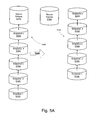
- FIG. 5A is a schematic illustration of a logical disk being split in accordance with an exemplary embodiment of the present invention.
- FIG. 5B is a schematic illustration of a logical disk being split in accordance with another exemplary embodiment of the present invention.
- Embodiments in accordance with the present invention are directed to managing snapshots in storage systems.
- One exemplary embodiment allows users to create unlimited number of snapshots under a Logical Disk.
- Existing snapshots associated with a Logical Disk are split or separated from the Logical Disk.
- the split snapshots are retained or stored as a standalone tree, which will not be affected if an overcommit occurs in the original Logical Disk or storage tree.
- Exemplary embodiments split one or more existing snapshots from the original Logical Disk and move these split snapshots to an independent and separate standalone tree. These split snapshots can be all of the snapshots of the Logical Disk or any user defined number. For instance, one or more of the oldest snapshots are split from the Logical Disk to create an independent snapshot tree. Exemplary embodiments create mirror clones or snapclones for a Logical Disk that already has snapshots.
- a source virtual disk In some storage area network systems, a source virtual disk (Vdisk) cannot be expanded or shrunk in size if it has snapshots. Exemplary embodiments enable splitting off all snapshots to a standalone snaptree which, in turn, allows the source Vdisk to be expanded or shrunk.
- Exemplary embodiments do not have a limit on a number of snapshots that can be created under a single Logical Disk. When a maximum number of snapshots is reached, users are not required to delete snapshots from the Logical Disk to create room for a newer snapshot. Instead, exemplary embodiments enable a user to selectively save old or existing snapshots. By separating snapshots from the Logical Disk and splitting them to a standalone tree, existing or old snapshots are not required to be deleted.
- exemplary embodiments are not limited to creating snapshots that all have a same redundant array of independent disks (RAID) type. If a user creates first RAID level snapshots and later decides to increase or change to second RAID level protection, the user can create a different RAID level under the same tree without deleting all the prior snapshots. For example, if a user creates RAID level 0 snapshots under a Logical Disk, these snapshots can be split from the Logical Disk. Then, under the same tree, the user can change the RAID designation (example, to RAID level 5) for subsequent snapshots to the same Logical Disk. The RAID level 0 snapshots are not required to be deleted.
- RAID redundant array of independent disks
- exemplary embodiments enable a user to increase RAID protection of snapshots after the tree is split. For example, if the Source Vdisk is RAID 1 and the snapshots are RAID 6 while the snapshots are in the same tree as the Source Vdisk, the snapshots really only have RAID 1 protection because they share data with the Source Vdisk. A loss of two RAID 1 drives will cause the Source Vdisk and all snapshots to be inaccessible. After the tree is split, the Source Vdisk is still RAID 1. The Snapshots are still RAID 6, but are now an independent tree. Thus a loss of two RAID 1 drives will cause the Source Vdisk to be inaccessible but all the snapshots in the new tree will still be accessible (possibly for recovery of the Source Vdisk). Having snapshots of a higher raid protection and increased storage efficiency, like RAID 6, have benefit for on-line archiving and recovery situations, for example.
- the subject matter is implemented in a storage architecture that provides virtualized data storage at a system level, such that virtualization is implemented within one or more storage area networks (SANs).
- SANs storage area networks
- the computing systems that utilize storage are referred to as hosts.
- a host is any computing system that consumes data storage resources capacity on its own behalf, or on behalf of systems coupled to the host.
- a host is a computer processing large databases, a transaction processing server maintaining transaction records, and the like.
- the host is a file server on a local area network (LAN) or wide area network (WAN) that provides storage services for an enterprise.
- LAN local area network
- WAN wide area network
- such a host includes one or more disk controllers or RAID controllers configured to manage multiple directly attached disk drives.
- a host connects to the SAN through one or more high-speed connection technology, such as a fibre channel (FC) fabric.
- FC fibre channel
- a virtualized SAN architecture comprises a group of storage cells, where each storage cell includes a pool of storage devices called a disk group.
- Each storage cell comprises parallel storage controllers coupled to the disk group.
- the storage controllers couple to the storage devices through a fibre channel arbitrated loop connection or through a network, such as a fibre channel fabric or the like.
- the storage controllers are also coupled to each other through point-to-point connections to enable them to cooperatively manage the presentation of storage capacity to computers using the storage capacity.
- the network architectures described herein represent a distributed computing environment, such as an enterprise computing system using a private SAN. However, the network architectures are readily scaled upwardly or downwardly to meet the needs of a particular application.
- FIG. 1 is a schematic illustration of an exemplary implementation of a networked computing system 100 that utilizes a storage network in accordance with an exemplary embodiment of the present invention.
- the storage pool 110 is implemented as a virtualized storage pool.
- a plurality of logical disks (also called logical units or LUNs) 112 a , 112 b are allocated within storage pool 110 .
- Each LUN 112 a , 112 b comprises a contiguous range of logical addresses that are addressed by host devices 120 , 122 , 124 and 128 by mapping requests from the connection protocol used by the host device to the uniquely identified LUN 112 a , 112 b .
- a host such as server 128 , provides services to other computing or data processing systems or devices.
- client computer 126 accesses storage pool 110 via a host, such as server 128 .
- Server 128 provides file services to client 126 and provides other services such as transaction processing services, email services, etc.
- client device 126 may or may not directly use the storage consumed by host 128 .
- Devices such as wireless device 120 , and computers 122 , 124 , which also may serve as hosts, logically couple directly to LUNs 112 a , 112 b .
- Hosts 120 - 128 can couple to multiple LUNs 112 a , 112 b , and LUNs 112 a , 112 b and include memory, mass storage, and a degree of data processing capability sufficient to manage a network connection.
- a LUN such as LUN 112 a , 112 b , comprises one or more redundant stores (RStore) that are a fundamental unit of reliable storage.
- RStore comprises an ordered set of physical storage segments (PSEGs) with associated redundancy properties and is contained entirely within a single redundant store set (RSS).
- PSEGs are analogous to disk drives and each RSS is analogous to a RAID storage set comprising a plurality of drives.
- the PSEGs that implement a particular LUN are spread across any number of physical storage disks.
- the physical storage capacity that a particular LUN 112 a , 112 b represents is configured to implement a variety of storage types offering varying capacity, reliability and availability features. For example, some LUNs represent striped, mirrored, and/or parity-protected storage. Other LUNs represent storage capacity that is configured without striping, redundancy, or parity protection.
- an RSS comprises a subset of physical disks in a Logical Device Allocation Domain (LDAD) and includes from six to eleven physical drives (which can change dynamically).
- the physical drives can have disparate capacities.
- physical drives within an RSS are assigned indices (e.g., 0, 1, 2, . . . , 11) for mapping purposes and are organized as pairs (i.e., adjacent odd and even indices) for RAID-1 purposes. Because data protection is spread within an RSS in accordance with one exemplary embodiment, and not across multiple RSSs, a disk failure in one RSS has no effect on the availability of any other RSS.
- a SAN manager appliance 109 is coupled to a management logical disk set (MLD) 111 which is a metadata container describing the logical structures used to create LUNs 112 a , 112 b , LDADs 103 a , 103 b , and other logical structures used by the system.
- MLD management logical disk set
- a portion of the physical storage capacity available in storage pool 101 is reserved as quorum space 113 and cannot be allocated to LDADs 103 a , 103 b , and hence cannot be used to implement LUNs 112 a , 112 b .
- each physical disk that participates in storage pool 110 has a reserved amount of capacity (e.g., the first “n” physical sectors) that may be designated as quorum space 113 .
- MLD 111 is mirrored in this quorum space of multiple physical drives and so can be accessed even if a drive fails.
- at least one physical drive is associated with each LDAD 103 a , 103 b includes a copy of MLD 111 (designated a “quorum drive”).
- SAN management appliance 109 can associate information such as name strings for LDADs 103 a , 103 b and LUNs 112 a , 112 b , and timestamps for objects. To facilitate this behavior, the management agent uses MLD 111 to store this information as metadata.
- MLD 111 is created implicitly upon creation of each LDAD 103 a , 103 b.
- Quorum space 113 is used to store information including physical store ID (a unique ID for each physical drive), version control information, type (quorum/non-quorum), RSS ID (identifies to which RSS this disk belongs), RSS Offset (identifies this disk's relative position in the RSS), Storage Cell ID (identifies to which storage cell this disk belongs), PSEG size, as well as state information indicating whether the disk is a quorum disk, for example.
- This metadata PSEG also contains a PSEG free list for the entire physical store, probably in the form of an allocation bitmap.
- quorum space 113 contains the PSEG allocation records (PSARs) for every PSEG on the physical disk.
- the PSAR comprises a PSAR signature, Metadata version, PSAR usage, and an indication a RSD to which this PSEG belongs.
- CSLD 114 is another type of metadata container comprising logical drives that are allocated out of address space within each LDAD 103 a , 103 b , but that, unlike LUNs 112 a , 112 b , can span multiple LDADs 103 a , 103 b .
- each LDAD 103 a , 103 b includes space allocated to CSLD 114 .
- CSLD 114 holds metadata describing the logical structure of a given LDAD 103 a , 103 b , including a primary logical disk metadata container (PLDMC) that contains an array of descriptors (called RSDMs) that describe every RStore used by each LUN 112 a , 112 b implemented within the LDAD 103 a , 103 b .
- PLDMC primary logical disk metadata container
- RSDMs descriptors
- the CSLD 114 implements metadata that is regularly used for tasks such as disk creation, leveling, RSS merging, RSS splitting, and regeneration.
- This metadata includes state information for each physical disk that indicates whether the physical disk is “Normal” (i.e., operating as expected), “Missing” (i.e., unavailable), “Merging” (i.e., a missing drive that has reappeared and must be normalized before use), “Replace” (i.e., the drive is marked for removal and data must be copied to a distributed spare), and “Regen” (i.e., the drive is unavailable and requires regeneration of its data to a distributed spare).
- a logical disk directory (LDDIR) data structure is a directory of all LUNs 1112 a , 112 b in any LDAD 103 a , 103 b .
- An entry in the LDDS comprises a universally unique ID (UUID) an RSD indicating the location of a Primary Logical Disk Metadata Container (PLDMC) for that LUN 112 a , 112 b .
- the RSD is a pointer to the base RSDM or entry point for the corresponding LUN 112 a , 112 b .
- metadata specific to a particular LUN 112 a , 112 b can be accessed by indexing into the LDDIR to find the base RSDM of the particular LUN 112 a , 112 b .
- the metadata within the PLDMC e.g., mapping structures described hereinbelow
- mapping structures described hereinbelow can be loaded into memory to realize the particular LUN 112 a , 112 b.
- the storage pool depicted in FIG. 1 implements multiple forms of metadata that can be used for recovery.
- the CSLD 114 implements metadata that is regularly used for tasks such as disk creation, leveling, RSS merging, RSS splitting, and regeneration.
- the PSAR metadata held in a known location on each disk contains metadata in a more rudimentary form that is not mapped into memory, but can be accessed when needed from its known location to regenerate all metadata in the system.
- Each of the devices shown in FIG. 1 can include memory, mass storage, and a degree of data processing capability sufficient to manage a network connection.
- the computer program devices in accordance with the present invention are implemented in the memory of the various devices shown in FIG. 1 and enabled by the data processing capability of the devices shown in FIG. 1 .
- an individual LDAD 103 a , 103 b corresponds to from as few as four disk drives to as many as several thousand disk drives. In particular examples, a minimum of eight drives per LDAD is required to support RAID-1 within the LDAD 103 a , 103 b using four paired disks.
- LUNs 112 a , 112 b defined within an LDAD 103 a , 103 b represent a few megabytes of storage or less, up to 2 TByte of storage or more. Hence, hundreds or thousands of LUNs 112 a , 112 b can be defined within a given LDAD 103 a , 103 b , and thus serve a large number of storage needs.
- a large enterprise can be served by a single storage pool 110 providing both individual storage dedicated to each workstation in the enterprise as well as shared storage across the enterprise.
- an enterprise can implement multiple LDADs 103 a , 103 b and/or multiple storage pools 1101 to provide a virtually limitless storage capability.
- the virtual storage system in accordance with the present description offers great flexibility in configuration and access.
- FIG. 2 is a schematic illustration of an exemplary storage network 200 that implements a storage pool, such as storage pool 110 .
- Storage network 200 comprises a plurality of storage cells 210 a , 210 b , 210 c connected by a communication network 212 .
- Storage cells 210 a , 210 b , 210 c are implemented as one or more communicatively connected storage devices.
- Client computers 214 a , 214 b , 214 c access storage cells 210 a , 210 b , 210 c through a host, such as servers 216 , 220 .
- Clients 214 a , 214 b , 214 c are connected to file server 216 directly, or via a network 218 such as a Local Area Network (LAN) or a Wide Area Network (WAN).
- LAN Local Area Network
- WAN Wide Area Network
- the number of storage cells 210 a , 210 b , 210 c that can be included in any storage network is limited primarily by the connectivity implemented in the communication network 212 .
- a switching fabric comprising a single FC switch can interconnect 256 or more ports, providing a possibility of hundreds of storage cells 210 a , 210 b , 210 c in a single storage network.
- FIG. 3 is a schematic illustration of an exemplary computing device 330 that is utilized to implement a host.
- Computing device 330 includes one or more processors or processing units 332 , a system memory 334 , and a bus 336 that couples various system components including the system memory 334 to processors 332 .
- the bus 336 represents one or more of any of several types of bus structures, including a memory bus or memory controller, a peripheral bus, an accelerated graphics port, and a processor or local bus using any of a variety of bus architectures.
- the system memory 334 includes read only memory (ROM) 338 and random access memory (RAM) 340 .
- a basic input/output system (BIOS) 342 containing the basic routines that help to transfer information between elements within computing device 330 , such as during start-up, is stored in ROM 338 .
- BIOS basic input/output system
- Computing device 330 further includes a hard disk drive 344 for reading from and writing to a hard disk (not shown) and includes one or more of a magnetic disk drive 346 for reading from and writing to a removable magnetic disk 348 , an optical disk drive 350 for reading from or writing to a removable optical disk 352 such as a CD ROM, or other optical media.
- the hard disk drive 344 , magnetic disk drive 346 , and optical disk drive 350 are connected to the bus 336 by a SCSI interface 354 or some other appropriate interface.
- the drives and their associated computer-readable media provide nonvolatile storage of computer-readable instructions, data structures, program modules and other data for computing device 330 .
- exemplary environment described herein employs a hard disk, a removable magnetic disk 348 and a removable optical disk 352
- other types of computer-readable media such as magnetic cassettes, flash memory cards, digital video disks, random access memories (RAMs), read only memories (ROMs), and the like, can also be used in the exemplary operating environment.
- a number of program modules can be stored on the hard disk 344 , magnetic disk 348 , optical disk 352 , ROM 338 , or RAM 340 , including an operating system 358 , one or more application programs 360 , other program modules 362 , and program data 364 .
- a user enters commands and information into computing device 330 through input devices such as a keyboard 366 and a pointing device 368 .
- Other input devices include a microphone, joystick, game pad, satellite dish, scanner, or the like.
- These and other input devices are connected to the processing unit 332 through an interface 370 that is coupled to the bus 336 .
- a monitor 372 or other type of display device is also connected to the bus 336 via an interface, such as a video adapter 374 .
- Computing device 330 operates in a networked environment using logical connections to one or more remote computers, such as a remote computer 376 .
- the remote computer 376 can be a personal computer, a server, a router, a network PC, a peer device or other common network node, and typically includes many or all of the elements described above relative to computing device 330 , although only a memory storage device 378 has been illustrated in FIG. 3 .
- the logical connections depicted in FIG. 3 include a LAN 380 and a WAN 382 .
- computing device 330 When used in a LAN networking environment, computing device 330 is connected to the local network 380 through a network interface or adapter 384 . When used in a WAN networking environment, computing device 330 typically includes a modem 386 or other means for establishing communications over the wide area network 382 , such as the Internet. The modem 386 , which may be internal or external, is connected to the bus 336 via a serial port interface 356 . In a networked environment, program modules depicted relative to the computing device 330 , or portions thereof, may be stored in the remote memory storage device. It will be appreciated that the network connections shown are exemplary and other means of establishing a communications link between the computers may be used.
- Hosts 216 , 220 include host adapter hardware and software to enable a connection to communication network 212 .
- the connection to communication network 212 is through an optical coupling or more conventional conductive cabling depending on the bandwidth requirements.
- a host adapter is implemented as a plug-in card on computing device 330 .
- Hosts 216 , 220 may implement any number of host adapters to provide as many connections to communication network 212 as the hardware and software support.
- the data processors of computing device 330 are programmed by means of instructions stored at different times in the various computer-readable storage media of the computer.
- Programs and operating systems can be distributed, for example, on floppy disks, CD-ROMs, or electronically, and are installed or loaded into the secondary memory of a computer. At execution, the programs are loaded at least partially into the computer's primary electronic memory.
- the storage capacity provided by arrays of disk drives is added to the storage pool.
- logic instructions on a host computer establish a LUN from storage capacity available on the arrays of disk drives available in one or more storage sites. It will be appreciated that, because a LUN is a logical unit, not necessarily a physical unit, the physical storage space that constitutes the LUN may be distributed across multiple storage cells. Data for the application is stored on one or more LUNs in the storage network. An application that needs to access the data queries a host computer, which retrieves the data from the LUN and forwards the data to the application.
- one or more of the storage cells in the storage network can implement RAID-based storage.
- RAID Redundant Array of Independent Disks
- RAID systems are disk array systems in which part of the physical storage capacity is used to store redundant data.
- RAID systems are typically characterized as one of six architectures, enumerated under the acronym RAID.
- snapshot is copy of one or more LUNs, files, and/or directories as they were at a particular point in time.
- a snapshot shares data with its successor (Source Vdisk) until that data has diverged (i.e. new writes to the Source Vdisk or snapshot).
- a snapshot requires allocation of new storage on the backend drives when the data diverges from the Source Vdisk.
- instant restore refers to a restore operation in which a source volume is restored to a previous point-in-time using a snapshot, and in which the data is available for access contemporaneously.
- FIG. 4A is a schematic high-level illustration of a data storage architecture in accordance with one embodiment.
- a source volume 410 which may also be referred to as a source virtual disk (Vdisk) is embodied as a logical unit number (LUN) or a logical disk (LD) that includes production data for one or more applications.
- LUN logical unit number
- LD logical disk
- One or more snapshots 412 , 414 , 416 include a point-in-time representation of source volume 410 .
- snapshots 412 , 414 , 416 are logically linked, example by pointers in one or more memory structures.
- snapshot 1 ( 412 ) represents a snapshot of the data taken at a first point in time
- snapshot 2 ( 414 ) represents a snapshot taken at a second point in time, later than the first point in time. Snapshots are linked in a serial fashion.
- snapshot n ( 416 ) represents the most recent point in time copy of source volume 410 .
- one or more of snapshots 412 , 414 , 416 reserve the space on one or more physical drives necessary to hold a copy of the data in source volume 410 .
- one or more of snapshots 412 , 414 , 416 does not reserve space on one or more physical drives to hold a copy of the data in source volume 710 . Rather, physical storage space for the snapshot 412 , 414 , 416 is allocated on demand as the data is written into the snapshot.
- a space efficient snapshot consumes less storage space than a space-inefficient snapshot, but creates a possibility of reaching an overcommit state, in which the physical storage lacks sufficient storage capacity to hold the snapshot.
- one exemplary embodiment reclaims reserved capacity by changing the snapshots from space inefficient to space efficient. For instance, maybe the snapshots were space inefficient when first created off the Source Vdisk to ensure that they would not overcommit. Now when they are split off, they are more static and will not change much (if at all). It may be beneficial for the user to reclaims this reserved space.
- FIG. 4B is a schematic high-level illustration of a data storage architecture in accordance with another embodiment.
- a source volume 420 has a mirrored clone 430 that includes a complete copy of the data in source volume 420 or a point in time complete copy of the data in source volume 420 .
- One or more snapshots 432 , 434 , 436 are taken of mirrored clone 430 .
- mirror clone 430 resides in a different logical disk allocation domain (LDAD) from the source volume 420 . This configuration permits the mirror clone data to reside on a different set of disks from the source volume, which provides performance and fault tolerance benefits.
- LDAD logical disk allocation domain
- one exemplary embodiment uses a read/write (R/W) mode that sets the write cache of the new tree to “write through” and has the EVA fail any new writes that would cause the tree to go overcommit.
- R/W read/write
- FIGS. 5A and 5B are schematic illustrations of a logical disk or source volume being split in accordance with an exemplary embodiment of the present invention.
- FIG. 5A illustrates a snapshot tree 500 A being split at two different points.
- the split point is at snapshot Sn (i.e., snapshot 520 A)
- the original source volume 510 A example, logical disk
- a new snapshot tree 502 A exist.
- the source volume 510 A has no snapshots, while the new tree 502 A has a plurality of snapshots previously associated with the source volume 510 A (snapshots being showns as 512 A- 520 A).
- a top snapshot 520 A (previously associated with source volume 510 A) now forms the top of tree 502 A.
- snaptree preserves the point-in-time of copies of all snapshots.
- Embodiments in accordance with the present invention are not limited to any particular number of splits.
- tree 502 A can be further split one, two, three, etc. more times depending on the number, n, of snapshots.
- the tree is split so each snapshot previously associated with the Logical Disk results in a separate and independent standalone tree.
- the tree is split so the new tree is a standalone tree, but metadata is kept that still associates 520 A with 510 A for the purpose of a future restore, but not for sharing data.
- Embodiments in accordance with the present invention are also not limited to any particular location for forming a split.
- FIG. 5B shows a snapshot tree 500 B that is split to result in two different independent trees. If the split occurs along snapshot 516 B, then the source volume 510 B has two snapshots 520 B and 518 B, while the newly formed tree 502 B has three snapshots ( 516 B, 514 B, and 512 B). Thus, two new independent and separate trees are formed. After the split, the Logical Disk or source volume 510 B can receive additional snapshots. Also Snapshot 516 B, now a top level LD can also receive additional snapshots.
- Exemplary embodiments enable users to create new RAID type of snapshots by splitting all existing snapshots off the original Logical Disk while keeping all the existing snapshots in a standalone tree. Such embodiments also enable creation of mirror clones or snapclones for the Logical Disk after the splitting.
- managing the snapshot splitting is implemented in snapshot/snapclone code (example, enterprise virtual array (EVA) firmware).
- snapshot/snapclone code example, enterprise virtual array (EVA) firmware.
- EVA enterprise virtual array
- a snapclone unshare process is utilized to unshare a chosen snapshot, which will turn the snapshot into a clone with all predecessor snapshots still under it.
- the use of sharing bits and architecture in place in the firmware allows the implementation of this solution to be simple and efficient.
- one algorithm to perform the unsharing or split is as follows:
- Si uses more space if it was a space efficient snapshot before the splitting because the shared data between Si and Si+1 now have another copy residing in Si.
- This embodiment is good for data redundancy but has potential to get into overcommit during the splitting. However, such overcommit is handled by just stopping the split or by adding some checks to forecast the capacity needed for splitting. User can also avoid overcommit by making sure there is enough space before initiating a request for the splitting.
- the new snapshot tree is put back to where it was before or attached to a mirrorclone/snapclone of the same original Logical Disk in a different LDAD.
- One embodiment performs splitting of the tree without copy shared data from Si+1 to Si and just enables the new tree to remember where it was split-off so that the data can be found later.
- disk array means a linked group of one or more independent disk drives.
- the disk arrays include daisy chain configuration or RAID technology and organize data storage into logical units (LUNs) that appear as linear blocks to clients.
- LUNs logical units
- embodiments are automated.
- apparatus, systems, and methods occur automatically.
- the terms “automated” or “automatically” mean controlled operation of an apparatus, system, and/or process using computers and/or mechanical/electrical devices without the necessity of human intervention, observation, effort and/or decision. For instance, splitting of the logical disk occurs automatically. In another embodiment, splitting occurs based on or in response to user commands.
- embodiments are implemented as a method, system, and/or apparatus.
- exemplary embodiments and steps associated therewith are implemented as firmware (example firmware on a controller board) and/or as one or more computer software programs to implement the methods described herein.
- the software is implemented as one or more modules (also referred to as code subroutines, or “objects” in object-oriented programming). The location of the software will differ for the various alternative embodiments.
- the software programming code for example, is accessed by a processor or processors of the computer or server from long-term storage media of some type, such as a CD-ROM drive or hard drive.
- the software programming code is embodied or stored on any of a variety of known media for use with a data processing system or in any memory device such as semiconductor, magnetic and optical devices, including a disk, hard drive, CD-ROM, ROM, etc.
- the code is distributed on such media, or is distributed to users from the memory or storage of one computer system over a network of some type to other computer systems for use by users of such other systems.
- the programming code is embodied in the memory and accessed by the processor using the bus.
Abstract
Description
| For a given snapshot Si for splitting, do | ||
| For each Rseg | ||
| if Si shares data with it succecessor Si+1 | ||
| Copy data from the Si+1 to Si | ||
| Set Si+1 share with predecessor bit = 0 | ||
| Set Si share with successor bit = 0 | ||
| Delink Si from Si+1 by update metadata. | ||
Claims (20)
Priority Applications (1)
| Application Number | Priority Date | Filing Date | Title |
|---|---|---|---|
| US11/586,930 US8046534B2 (en) | 2006-10-26 | 2006-10-26 | Managing snapshots in storage systems |
Applications Claiming Priority (1)
| Application Number | Priority Date | Filing Date | Title |
|---|---|---|---|
| US11/586,930 US8046534B2 (en) | 2006-10-26 | 2006-10-26 | Managing snapshots in storage systems |
Publications (2)
| Publication Number | Publication Date |
|---|---|
| US20080104139A1 US20080104139A1 (en) | 2008-05-01 |
| US8046534B2 true US8046534B2 (en) | 2011-10-25 |
Family
ID=39331633
Family Applications (1)
| Application Number | Title | Priority Date | Filing Date |
|---|---|---|---|
| US11/586,930 Active 2030-08-23 US8046534B2 (en) | 2006-10-26 | 2006-10-26 | Managing snapshots in storage systems |
Country Status (1)
| Country | Link |
|---|---|
| US (1) | US8046534B2 (en) |
Cited By (3)
| Publication number | Priority date | Publication date | Assignee | Title |
|---|---|---|---|---|
| US20110213765A1 (en) * | 2010-02-26 | 2011-09-01 | Vmware, Inc. | Comprehensive, Relevant, and Dynamic Data Searching in a Virtualization Environment |
| US9996424B2 (en) | 2015-06-30 | 2018-06-12 | International Business Machines Corporation | Splitting a clone having snapshots from a parent |
| TWI657374B (en) * | 2017-05-02 | 2019-04-21 | 廣達電腦股份有限公司 | Sas hard disk drive update via management controller and system using the same |
Families Citing this family (16)
| Publication number | Priority date | Publication date | Assignee | Title |
|---|---|---|---|---|
| US7769722B1 (en) * | 2006-12-08 | 2010-08-03 | Emc Corporation | Replication and restoration of multiple data storage object types in a data network |
| US7613945B2 (en) | 2003-08-14 | 2009-11-03 | Compellent Technologies | Virtual disk drive system and method |
| US9489150B2 (en) * | 2003-08-14 | 2016-11-08 | Dell International L.L.C. | System and method for transferring data between different raid data storage types for current data and replay data |
| US7373366B1 (en) | 2005-06-10 | 2008-05-13 | American Megatrends, Inc. | Method, system, apparatus, and computer-readable medium for taking and managing snapshots of a storage volume |
| US8046547B1 (en) | 2007-01-30 | 2011-10-25 | American Megatrends, Inc. | Storage system snapshots for continuous file protection |
| US8082407B1 (en) | 2007-04-17 | 2011-12-20 | American Megatrends, Inc. | Writable snapshots for boot consolidation |
| US8364639B1 (en) * | 2007-10-11 | 2013-01-29 | Parallels IP Holdings GmbH | Method and system for creation, analysis and navigation of virtual snapshots |
| US20090229626A1 (en) * | 2008-03-11 | 2009-09-17 | Wei-Cheng Hsu | Firm structured hair clip |
| CN102177496A (en) * | 2008-08-07 | 2011-09-07 | 康佩伦特科技公司 | System and method for transferring data between different RAID data storage types for current data and replay data |
| US20120096230A1 (en) * | 2010-10-14 | 2012-04-19 | Kishore Sampathkumar | Method and system for creating snapclone logical disks |
| US9298372B2 (en) * | 2013-03-06 | 2016-03-29 | Dell Products, L.P. | System and method for managing storage system snapshots |
| US9921769B2 (en) | 2014-06-19 | 2018-03-20 | Cohesity, Inc. | Making more active use of a secondary storage system |
| US10430434B2 (en) * | 2016-01-20 | 2019-10-01 | Delphix Corporation | Managing transformed snapshots in a storage system |
| CN107291579B (en) * | 2017-07-05 | 2020-03-31 | 郑州云海信息技术有限公司 | Metadata cluster file snapshot method based on static subtree partition |
| US10754735B2 (en) * | 2017-11-20 | 2020-08-25 | Salesforce.Com, Inc. | Distributed storage reservation for recovering distributed data |
| US11132331B2 (en) * | 2017-12-12 | 2021-09-28 | Rubrik, Inc. | Sharding of full and incremental snapshots |
Citations (3)
| Publication number | Priority date | Publication date | Assignee | Title |
|---|---|---|---|---|
| US7100089B1 (en) * | 2002-09-06 | 2006-08-29 | 3Pardata, Inc. | Determining differences between snapshots |
| US7404051B2 (en) * | 2005-04-18 | 2008-07-22 | Hitachi, Ltd. | Method for replicating snapshot volumes between storage systems |
| US7788244B2 (en) * | 2007-07-31 | 2010-08-31 | Hewlett-Packard Development Company, L.P. | Method and system for copying a snapshot tree |
-
2006
- 2006-10-26 US US11/586,930 patent/US8046534B2/en active Active
Patent Citations (3)
| Publication number | Priority date | Publication date | Assignee | Title |
|---|---|---|---|---|
| US7100089B1 (en) * | 2002-09-06 | 2006-08-29 | 3Pardata, Inc. | Determining differences between snapshots |
| US7404051B2 (en) * | 2005-04-18 | 2008-07-22 | Hitachi, Ltd. | Method for replicating snapshot volumes between storage systems |
| US7788244B2 (en) * | 2007-07-31 | 2010-08-31 | Hewlett-Packard Development Company, L.P. | Method and system for copying a snapshot tree |
Non-Patent Citations (1)
| Title |
|---|
| U.S. Appl. No. 11/404,240, Aaron Lindemann. |
Cited By (7)
| Publication number | Priority date | Publication date | Assignee | Title |
|---|---|---|---|---|
| US20110213765A1 (en) * | 2010-02-26 | 2011-09-01 | Vmware, Inc. | Comprehensive, Relevant, and Dynamic Data Searching in a Virtualization Environment |
| US9135342B2 (en) * | 2010-02-26 | 2015-09-15 | Vmware, Inc. | Comprehensive, relevant, and dynamic data searching in a virtualization environment |
| US9996424B2 (en) | 2015-06-30 | 2018-06-12 | International Business Machines Corporation | Splitting a clone having snapshots from a parent |
| US10223209B2 (en) | 2015-06-30 | 2019-03-05 | International Business Machines Corporation | Splitting a clone having snapshots from a parent |
| TWI657374B (en) * | 2017-05-02 | 2019-04-21 | 廣達電腦股份有限公司 | Sas hard disk drive update via management controller and system using the same |
| US10747437B2 (en) | 2017-05-02 | 2020-08-18 | Quanta Computer Inc. | SAS hard disk drive update via management controller |
| US10884624B2 (en) | 2017-05-02 | 2021-01-05 | Quanta Computer Inc. | SAS/SATA hard disk drive update via management controller |
Also Published As
| Publication number | Publication date |
|---|---|
| US20080104139A1 (en) | 2008-05-01 |
Similar Documents
| Publication | Publication Date | Title |
|---|---|---|
| US8046534B2 (en) | Managing snapshots in storage systems | |
| US7467268B2 (en) | Concurrent data restore and background copy operations in storage networks | |
| US6915397B2 (en) | System and method for generating point in time storage copy | |
| KR100439675B1 (en) | An efficient snapshot technique for shated large storage | |
| US7305530B2 (en) | Copy operations in storage networks | |
| US20060106893A1 (en) | Incremental backup operations in storage networks | |
| US7159150B2 (en) | Distributed storage system capable of restoring data in case of a storage failure | |
| US9460102B1 (en) | Managing data deduplication in storage systems based on I/O activities | |
| US20100049931A1 (en) | Copying Logical Disk Mappings Between Arrays | |
| US7716183B2 (en) | Snapshot preserved data cloning | |
| US8612382B1 (en) | Recovering files in data storage systems | |
| US6973556B2 (en) | Data element including metadata that includes data management information for managing the data element | |
| US8204858B2 (en) | Snapshot reset method and apparatus | |
| US8615641B2 (en) | System and method for differential backup | |
| EP1653360A2 (en) | Recovery operations in storage networks | |
| US9842117B1 (en) | Managing replication of file systems | |
| US8850145B1 (en) | Managing consistency groups in storage systems | |
| US10809932B1 (en) | Managing data relocations in storage systems | |
| US9218138B1 (en) | Restoring snapshots to consistency groups of mount points | |
| US20050097132A1 (en) | Hierarchical storage system | |
| US11003554B2 (en) | RAID schema for providing metadata protection in a data storage system | |
| US9063892B1 (en) | Managing restore operations using data less writes | |
| US10409687B1 (en) | Managing backing up of file systems | |
| US9477675B1 (en) | Managing file system checking in file systems | |
| US11188425B1 (en) | Snapshot metadata deduplication |
Legal Events
| Date | Code | Title | Description |
|---|---|---|---|
| AS | Assignment |
Owner name: HEWLETT-PACKARD DEVELOPMENT COMPANY, L.P., TEXAS Free format text: ASSIGNMENT OF ASSIGNORS INTEREST;ASSIGNORS:XU, XIA;LINDEMANN, AARON;REEL/FRAME:018470/0835 Effective date: 20061023 |
|
| STCF | Information on status: patent grant |
Free format text: PATENTED CASE |
|
| FPAY | Fee payment |
Year of fee payment: 4 |
|
| AS | Assignment |
Owner name: HEWLETT PACKARD ENTERPRISE DEVELOPMENT LP, TEXAS Free format text: ASSIGNMENT OF ASSIGNORS INTEREST;ASSIGNOR:HEWLETT-PACKARD DEVELOPMENT COMPANY, L.P.;REEL/FRAME:037079/0001 Effective date: 20151027 |
|
| MAFP | Maintenance fee payment |
Free format text: PAYMENT OF MAINTENANCE FEE, 8TH YEAR, LARGE ENTITY (ORIGINAL EVENT CODE: M1552); ENTITY STATUS OF PATENT OWNER: LARGE ENTITY Year of fee payment: 8 |
|
| AS | Assignment |
Owner name: SNOWFLAKE INC., CALIFORNIA Free format text: ASSIGNMENT OF ASSIGNORS INTEREST;ASSIGNOR:HEWLETT PACKARD ENTERPRISE DEVELOPMENT LP;REEL/FRAME:054969/0843 Effective date: 20201218 |
|
| MAFP | Maintenance fee payment |
Free format text: PAYMENT OF MAINTENANCE FEE, 12TH YEAR, LARGE ENTITY (ORIGINAL EVENT CODE: M1553); ENTITY STATUS OF PATENT OWNER: LARGE ENTITY Year of fee payment: 12 |