US8050341B2 - Method and apparatus for acquiring frequency of multi-path signal - Google Patents
Method and apparatus for acquiring frequency of multi-path signal Download PDFInfo
- Publication number
- US8050341B2 US8050341B2 US12/110,025 US11002508A US8050341B2 US 8050341 B2 US8050341 B2 US 8050341B2 US 11002508 A US11002508 A US 11002508A US 8050341 B2 US8050341 B2 US 8050341B2
- Authority
- US
- United States
- Prior art keywords
- region
- signal
- path signal
- sub
- target
- Prior art date
- Legal status (The legal status is an assumption and is not a legal conclusion. Google has not performed a legal analysis and makes no representation as to the accuracy of the status listed.)
- Expired - Fee Related, expires
Links
- 238000000034 method Methods 0.000 title claims abstract description 27
- 125000004122 cyclic group Chemical group 0.000 claims abstract description 33
- 238000011084 recovery Methods 0.000 claims description 3
- 230000003111 delayed effect Effects 0.000 description 9
- 238000004891 communication Methods 0.000 description 6
- 238000010586 diagram Methods 0.000 description 6
- 230000000694 effects Effects 0.000 description 3
- 238000005516 engineering process Methods 0.000 description 2
- 230000004075 alteration Effects 0.000 description 1
- 238000012986 modification Methods 0.000 description 1
- 230000004048 modification Effects 0.000 description 1
- 230000035945 sensitivity Effects 0.000 description 1
- 235000015096 spirit Nutrition 0.000 description 1
Images


Classifications
-
- H—ELECTRICITY
- H04—ELECTRIC COMMUNICATION TECHNIQUE
- H04L—TRANSMISSION OF DIGITAL INFORMATION, e.g. TELEGRAPHIC COMMUNICATION
- H04L27/00—Modulated-carrier systems
- H04L27/26—Systems using multi-frequency codes
- H04L27/2601—Multicarrier modulation systems
- H04L27/2647—Arrangements specific to the receiver only
- H04L27/2655—Synchronisation arrangements
- H04L27/2657—Carrier synchronisation
-
- H—ELECTRICITY
- H04—ELECTRIC COMMUNICATION TECHNIQUE
- H04L—TRANSMISSION OF DIGITAL INFORMATION, e.g. TELEGRAPHIC COMMUNICATION
- H04L27/00—Modulated-carrier systems
- H04L27/26—Systems using multi-frequency codes
- H04L27/2601—Multicarrier modulation systems
- H04L27/2647—Arrangements specific to the receiver only
- H04L27/2655—Synchronisation arrangements
- H04L27/2668—Details of algorithms
- H04L27/2673—Details of algorithms characterised by synchronisation parameters
- H04L27/2676—Blind, i.e. without using known symbols
- H04L27/2678—Blind, i.e. without using known symbols using cyclostationarities, e.g. cyclic prefix or postfix
-
- H—ELECTRICITY
- H04—ELECTRIC COMMUNICATION TECHNIQUE
- H04L—TRANSMISSION OF DIGITAL INFORMATION, e.g. TELEGRAPHIC COMMUNICATION
- H04L27/00—Modulated-carrier systems
- H04L27/26—Systems using multi-frequency codes
- H04L27/2601—Multicarrier modulation systems
- H04L27/2647—Arrangements specific to the receiver only
- H04L27/2655—Synchronisation arrangements
- H04L27/2668—Details of algorithms
- H04L27/2681—Details of algorithms characterised by constraints
- H04L27/2688—Resistance to perturbation, e.g. noise, interference or fading
Definitions
- the invention relates to a method and an apparatus for acquiring a target frequency, and more specifically, to a method and an apparatus for acquiring a target frequency of a multi-path signal.
- the orthogonal frequency division multiplexing is a multi-path modulating/demodulating technology with high efficiency.
- the theorem is to use several sub-carrier waves to transmit the data concurrently to improve the data transmitting rate.
- OFDM is used for dividing the available bandwidth into several narrow frequency bands to transmit data in parallel through these frequency bands. Due to the fact that the OFDM wireless communication system has advantages of: high data transmitting rate, high bandwidth using rate, and preventing the radio waves from the multi-path attenuation, the OFDM wireless communication system is widely applied to the new generation wireless communication system.
- the OFDM technology has its drawbacks, such as a high peak-to-average power ratio and a high sensitivity to the frequency error of the sub-channel. Therefore, in the OFDM wireless communication system, how the frequency recovering can be performed to achieve the effect of frequency synchronization is a very important topic.
- the conventional frequency synchronizing method for the multi-path signal is done by adding a cyclic prefix in front of the data sector in the signal. After the signal is received at the receiving end, the frequency/phase is estimated by using the cyclic prefix to obtain the synchronizing frequency. However, when the cyclic prefix is interfered, a serious error occurs in the frequency obtained by the phase estimation and causes a serious frequency departure.
- the main goal of the invention is to provide a method and an apparatus for acquiring a target frequency of a multi-path signal to solve the problems above.
- a preferred embodiment according to the invention is a method for acquiring a target frequency of a multi-path signal.
- the multi-path signal includes a first path signal and a second path signal. Firstly, the first path signal is received through a first path and the second path signal is received through a second path. Then, a target region is determined. The target region is a portion of a second cyclic prefix in the second path signal, which overlaps with a first cyclic prefix in the first path signal. Afterward, the target frequency is determined according to the target region.
- the apparatus includes a receiving module, a region determining module, and a frequency-determining module.
- the receiving module is used for receiving the first path signal through a first path and the second path signal through a second path.
- the region-determining module is used for determining a target region.
- the target region is a portion of a second cyclic prefix in the second path signal, which overlaps with a first cyclic prefix in the first path signal.
- the frequency-determining module is used for determining the target frequency according to the target region.
- FIG. 1 is a schematic diagram of a first path signal and a second path signal included in a multi-path signal according to the prior art.
- FIG. 2 is a flow diagram of the method for acquiring a target frequency of a multi-path signal in the first preferred embodiment according to the invention.
- FIG. 3 shows an example of the first path signal, the second path signal, and the delayed second path signal.
- FIG. 4 shows the step S 12 which further includes the sub-steps S 121 to S 123 .
- FIG. 5 shows the step S 13 which further includes the sub-steps S 131 to S 135 .
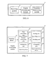
- FIG. 6 is a functional block diagram of the frequency-acquiring apparatus in the second preferred embodiment of the invention.
- FIG. 7 is a detailed functional block diagram of the region-determining module shown in FIG. 6 .
- the invention provides a method and an apparatus for acquiring a target frequency of a multi-path signal.
- the multi-path signal can be an OFDM signal.
- the multi-path signal includes a first path signal P 1 and a second path signal P 2 .
- a cyclic prefix 21 of the first path signal P 1 is generated by copying a data sector 23 to data 22 in the first path signal P 1 . Therefore, the content included in the cyclic prefix 21 is the same with the data sector 23 .
- the main difference between the first path signal P 1 and the second path signal P 2 is the time the second path signal received by a receiving end. Since the first path signal P 1 and the second path signal P 2 are signals from the same emitter, the difference between them is generated from the effect of the multi-path signal. Therefore, a cyclic prefix 24 of the second path signal P 2 is also the same with the cyclic prefix 21 of the first path signal P 1 .
- the cyclic prefix 21 is the same with the data sector (a combination of 25 A and 25 B) of the second path signal P 2 .
- the data sector 25 A is the same with the part marked 24 A in the cyclic prefix 24 .
- the data sector 25 B is the same with the part marked 24 B in the cyclic prefix 24 .
- the partial cyclic prefix 24 B of the second path signal P 2 has an overlap of time with the data 22 of the first path signal P 1 , the partial cyclic prefix 24 B will be interfered by the data 22 . If the frequency of the multi-path signal is directly estimated based on the cyclic prefix 24 , there will be a serious error. Therefore, in the method and apparatus according to the invention, the non-interfered cyclic prefix sector (as the region marked 24 A) is used as a target region, and the target region is used for further determining a target frequency of the multi-path signal.
- a preferred embodiment of the invention is a method for acquiring a target frequency of a multi-path signal.
- FIG. 2 is a flow diagram of the method.
- step S 11 is performed, the first path signal is received through a first path and the second path signal is received through a second path.
- step S 12 is performed, a target region is determined.
- the target region is a portion of a second cyclic prefix in the second path signal, which overlaps with a first cyclic prefix line fist path signal.
- step S 13 is performed, the target frequency is determined according to the target region.
- the target frequency is capable of being determined by a clock recovery process performed on the target region.
- the second path signal P 2 can be delayed to generate a delayed second path signal P 2 ′, and the target region can be found out by comparing the second path signal P 2 and the delayed second path signal P 2 ′.
- FIG. 3 shows an example of the first path signal P 1 , the second path signal P 2 and the delayed second path signal P 2 ′.
- the delayed second path signal P 2 ′ is generated by delaying the second path signal P 2 with the length L 22 of the data 22 .
- the combination of a data sector 26 and the target region 24 A in the second path signal P 2 can be seen as a first region; the combination of a data sector 27 and the target region 25 A can be seen as a second region.
- the data sector 26 in the delayed second path signal P 2 ′ overlaps with the data sector 27 in the second path signal P 2 .
- the target region 24 A in the delayed second path signal P 2 ′ overlaps with the data sector 25 A in the second path signal P 2 .
- the first region in the delayed second path signal P 2 ′ overlaps with the second region in the second path signal P 2 .
- the difference between the first region and the second region can be calculated to generate a differential signal.
- the contents of the data sector 25 A and the target region 24 A are the same. Therefore, the part corresponding to the data sector 25 A (namely, corresponding to the target region 24 A) in the differential signal should be substantially equal to 0.
- the data sector 26 in the first region is not necessarily related to the data sector 27 in the second region. Therefore, the part corresponding to the data sector 26 (namely, corresponding to the data sector 27 ) in the differential signal will not be equal to 0.
- the position of target region 24 A can be found from the differential signal by the method of the invention.
- the lengths of the first region, the second region, and the differential signal are all substantially equal to the length L 21 , of the cyclic prefix 21 .
- the step S 12 in FIG. 2 can include the sub-steps S 121 through S 123 .
- the sub-step S 121 is to select a first region and a second region from the second path signal.
- the first region includes the target region, and the second region includes an original region corresponding to the target region.
- the sub-step S 122 is to calculate the difference between the first region and the second region to generate a differential signal.
- the sub-step S 123 is to determine the target region according to the differential signal. The signal energy of the target region is smaller than a predetermined value.
- the sub-step S 122 can firstly calculate a set of first amplitudes in the first region and a set of second amplitudes in the second region. Then, the set of first amplitudes is subtracted from the set of second amplitudes to generate the differential signal.
- the differential signal can be set as a default region by the method of the invention.
- the default region can be further divided into a first sub-region and a second sub-region, and the total energies of the first sub-region and the second sub-region are compared. If the total energy of the first sub-region is larger than the total energy of the second sub-region and the energy difference is larger than an energy threshold, that is to say, when the signal strength of the first sub-region is much stronger than that of the second sub-region, the first sub-region with larger signal strength is set as the default region again. And, the steps above are repeated to divide the first sub-region into two sub-regions and their total energies are compared.
- the process is continued in this way until the energy difference between the two divided sub-regions is smaller than an energy threshold. At this time, the signal strengths of the two sub-regions are quite close.
- the part corresponding to the data sector 26 (namely, corresponding to the data sector 27 ) in the differential signal can be obtained by combining the two sub-regions.
- the range of the target region 24 A can be defined from the part corresponding to the data sector 26 in the differential signal.
- the above-mentioned step S 13 can be divided into the sub-steps S 131 through S 135 .
- the sub-step S 131 is to set the differential signal as a default region.
- the sub-step S 132 is to divide the default region into a first sub-region and a second sub-region.
- the sub-step S 133 is to generate an energy difference by comparing a first total energy of the first sub-region with a second total energy of the second sub-region. If the first total energy is larger than the second total energy and the energy difference is larger than an energy threshold, the sub-step S 134 is performed to set the first sub-region as the default region and the sub-steps S 132 through S 134 are repeated. If the energy difference is smaller than the energy threshold, the sub-step S 135 is performed to delete the first sub-region and the second sub-region from the differential signal to generate the target region.
- the second preferred embodiment of the invention is an apparatus for acquiring a target frequency of a multi-path signal.
- the multi-path signal includes a first path signal and a second path signal.
- FIG. 6 is a functional block diagram of the frequency acquiring apparatus.
- the frequency-acquiring apparatus 10 includes a receiving module 12 , a region determining module 14 , and a frequency-determining module 16 .
- the receiving module 12 is used for receiving the first path signal through a first path and the second path signal through a second path.
- the region-determining module 14 is used for determining a target region.
- the target region is a portion of a second cyclic prefix in the second path signal, which overlaps with a first cyclic prefix in the first path signal.
- the second cyclic prefix has a prefix length and the length of the differential signal is substantially equal to the prefix length.
- the frequency-determining module 16 is used for determining the target frequency according to the target region.
- the target frequency can be determined by a clock recovery process performed on the target region.
- the region-determining module 14 can include a selecting device 141 , a calculating device 142 , and a region-determining device 143 .
- the selecting device 141 is used for selecting a first region and a second region from the second path signal.
- the first region includes the target region, and the second region includes an original region corresponding to the target region.
- the calculating device 142 is electrically connected to the selecting device 141 and used for calculating the difference between the first region and the second region to generate a differential signal.
- the region-determining device 143 is used for determining the target region according to the differential signal, wherein the signal energy of the target region is smaller than a predetermined value.
- the calculating device 142 can include a first calculating unit 1421 , a second calculating unit 1422 , and a subtracting unit 1423 .
- the first calculating unit 1421 is used for calculating a set of first amplitudes in the first region.
- the second calculating unit 1422 is used for calculating a set of second amplitudes in the second region.
- the subtracting unit 1423 is electrically connected to the first calculating unit 1421 and the second calculating unit 1422 , which are used for generating the differential signal by subtracting the set of first amplitudes from the set of second amplitudes.
- FIG. 7 also shows that the region-determining device 143 can include a setting unit 1431 , a dividing unit 1432 , and a comparing unit 1433 .
- the setting unit 1431 is used for setting the differential signal as a default region.
- the dividing unit 1432 is electrically connected to the setting unit 1431 , and used for dividing the default region into a first sub-region and a second sub-region.
- the comparing unit 1433 is used for generating an energy difference by comparing a first total energy of the first sub-region with a second total energy of the second sub-region.
- the setting unit 1431 will set the first sub-region as the default region, and the dividing unit 1432 , as well as the comparing unit 1433 , are re-operated. If the energy difference is smaller than the energy threshold, the setting unit 1431 will combine the first sub-region and the second sub-region to generate the target region.
- a multi-path signal e.g., an OFDM signal
- a multi-path signal e.g., an OFDM signal
- a multi-path wireless communication system e.g., an OFDM wireless communication system
Abstract
Description
Claims (12)
Applications Claiming Priority (3)
| Application Number | Priority Date | Filing Date | Title |
|---|---|---|---|
| TW096114996A TWI337029B (en) | 2007-04-27 | 2007-04-27 | Method and apparatus for acquiring frequency of multi-path signal |
| TW096114996 | 2007-04-27 | ||
| TW96114996A | 2007-04-27 |
Publications (2)
| Publication Number | Publication Date |
|---|---|
| US20080267305A1 US20080267305A1 (en) | 2008-10-30 |
| US8050341B2 true US8050341B2 (en) | 2011-11-01 |
Family
ID=39886955
Family Applications (1)
| Application Number | Title | Priority Date | Filing Date |
|---|---|---|---|
| US12/110,025 Expired - Fee Related US8050341B2 (en) | 2007-04-27 | 2008-04-25 | Method and apparatus for acquiring frequency of multi-path signal |
Country Status (2)
| Country | Link |
|---|---|
| US (1) | US8050341B2 (en) |
| TW (1) | TWI337029B (en) |
Citations (1)
| Publication number | Priority date | Publication date | Assignee | Title |
|---|---|---|---|---|
| US20060215778A1 (en) * | 2005-03-11 | 2006-09-28 | Vinay Murthy | Automatic frequency control for a wireless communication system with multiple subcarriers |
-
2007
- 2007-04-27 TW TW096114996A patent/TWI337029B/en not_active IP Right Cessation
-
2008
- 2008-04-25 US US12/110,025 patent/US8050341B2/en not_active Expired - Fee Related
Patent Citations (1)
| Publication number | Priority date | Publication date | Assignee | Title |
|---|---|---|---|---|
| US20060215778A1 (en) * | 2005-03-11 | 2006-09-28 | Vinay Murthy | Automatic frequency control for a wireless communication system with multiple subcarriers |
Also Published As
| Publication number | Publication date |
|---|---|
| TW200843424A (en) | 2008-11-01 |
| TWI337029B (en) | 2011-02-01 |
| US20080267305A1 (en) | 2008-10-30 |
Similar Documents
| Publication | Publication Date | Title |
|---|---|---|
| CN110086742B (en) | Receiver and method for recovering payload data in a received signal | |
| TWI258937B (en) | Mode detection for OFDM signals | |
| US7522513B2 (en) | Method and system for receiving a multi-carrier signal | |
| CN1628446B (en) | Method and sytem for receiving multi-carrier signal | |
| JP2019506810A (en) | Transmitting apparatus, receiving apparatus, and method | |
| US20080095280A1 (en) | Correlation value calculation method and correlator using the same | |
| US20230115010A1 (en) | Systems and methods for multi-carrier signal echo management using pseudo-extensions | |
| EP1416629B1 (en) | Method and system for reducing noise in a multi-carrier signal | |
| JP2024023636A (en) | Transmission device and transmission method | |
| US8050341B2 (en) | Method and apparatus for acquiring frequency of multi-path signal | |
| US20050094747A1 (en) | Apparatus to estimate a channel using training sequence data for a digital receiver and a method thereof | |
| US9780975B1 (en) | Faster-Than-Nyquist (FTN) signal transmission apparatus and method thereof | |
| JP6906759B2 (en) | Acoustic communication system, acoustic receiver, acoustic transmitter and acoustic transmission method | |
| US6950475B1 (en) | OFDM receiver clock synchronization system | |
| JPH06232939A (en) | Frame synchronization circuit | |
| WO2017117732A1 (en) | Airborne acoustic communication channel equalization method and device based on channel characteristics | |
| JP2014216849A (en) | Communication system, reception device, semiconductor device, and reset method for communication system | |
| Jain et al. | Efficient performance analysis of OFDM based DAB systems using Reed Solomon coding technique | |
| CN106911413A (en) | A kind of overlapped time division multiplexing modulator approach, apparatus and system | |
| CN106911448A (en) | A kind of overlapped time division multiplexing modulator approach, apparatus and system | |
| MXPA06008553A (en) | Timing estimation in an ofdm receiver | |
| JP2004112840A (en) | System and method of transmitting/receiving orthogonal frequency division multiplexing signal |
Legal Events
| Date | Code | Title | Description |
|---|---|---|---|
| AS | Assignment |
Owner name: QISDA CORPORATION, TAIWAN Free format text: ASSIGNMENT OF ASSIGNORS INTEREST;ASSIGNORS:LIAO, XUE-JIAN;LIN, KUO-CHUAN;REEL/FRAME:020860/0273 Effective date: 20080420 |
|
| ZAAA | Notice of allowance and fees due |
Free format text: ORIGINAL CODE: NOA |
|
| ZAAB | Notice of allowance mailed |
Free format text: ORIGINAL CODE: MN/=. |
|
| STCF | Information on status: patent grant |
Free format text: PATENTED CASE |
|
| FPAY | Fee payment |
Year of fee payment: 4 |
|
| MAFP | Maintenance fee payment |
Free format text: PAYMENT OF MAINTENANCE FEE, 8TH YEAR, LARGE ENTITY (ORIGINAL EVENT CODE: M1552); ENTITY STATUS OF PATENT OWNER: LARGE ENTITY Year of fee payment: 8 |
|
| FEPP | Fee payment procedure |
Free format text: MAINTENANCE FEE REMINDER MAILED (ORIGINAL EVENT CODE: REM.); ENTITY STATUS OF PATENT OWNER: LARGE ENTITY |
|
| LAPS | Lapse for failure to pay maintenance fees |
Free format text: PATENT EXPIRED FOR FAILURE TO PAY MAINTENANCE FEES (ORIGINAL EVENT CODE: EXP.); ENTITY STATUS OF PATENT OWNER: LARGE ENTITY |
|
| STCH | Information on status: patent discontinuation |
Free format text: PATENT EXPIRED DUE TO NONPAYMENT OF MAINTENANCE FEES UNDER 37 CFR 1.362 |
|
| FP | Lapsed due to failure to pay maintenance fee |
Effective date: 20231101 |