US8050441B2 - Portable speakers - Google Patents
Portable speakers Download PDFInfo
- Publication number
- US8050441B2 US8050441B2 US11/144,879 US14487905A US8050441B2 US 8050441 B2 US8050441 B2 US 8050441B2 US 14487905 A US14487905 A US 14487905A US 8050441 B2 US8050441 B2 US 8050441B2
- Authority
- US
- United States
- Prior art keywords
- enclosure
- portable speaker
- connector
- driver
- configuration
- Prior art date
- Legal status (The legal status is an assumption and is not a legal conclusion. Google has not performed a legal analysis and makes no representation as to the accuracy of the status listed.)
- Expired - Fee Related, expires
Links
- 230000000694 effects Effects 0.000 claims description 5
- 239000003990 capacitor Substances 0.000 claims description 2
- 238000000926 separation method Methods 0.000 description 3
- 230000005484 gravity Effects 0.000 description 2
- 230000002889 sympathetic effect Effects 0.000 description 2
- 238000010276 construction Methods 0.000 description 1
- 238000005516 engineering process Methods 0.000 description 1
- -1 for example Substances 0.000 description 1
- 239000000463 material Substances 0.000 description 1
- 238000012986 modification Methods 0.000 description 1
- 230000004048 modification Effects 0.000 description 1
- 229920001690 polydopamine Polymers 0.000 description 1
Images


Classifications
-
- H—ELECTRICITY
- H04—ELECTRIC COMMUNICATION TECHNIQUE
- H04R—LOUDSPEAKERS, MICROPHONES, GRAMOPHONE PICK-UPS OR LIKE ACOUSTIC ELECTROMECHANICAL TRANSDUCERS; DEAF-AID SETS; PUBLIC ADDRESS SYSTEMS
- H04R1/00—Details of transducers, loudspeakers or microphones
- H04R1/02—Casings; Cabinets ; Supports therefor; Mountings therein
- H04R1/025—Arrangements for fixing loudspeaker transducers, e.g. in a box, furniture
-
- H—ELECTRICITY
- H04—ELECTRIC COMMUNICATION TECHNIQUE
- H04R—LOUDSPEAKERS, MICROPHONES, GRAMOPHONE PICK-UPS OR LIKE ACOUSTIC ELECTROMECHANICAL TRANSDUCERS; DEAF-AID SETS; PUBLIC ADDRESS SYSTEMS
- H04R1/00—Details of transducers, loudspeakers or microphones
- H04R1/02—Casings; Cabinets ; Supports therefor; Mountings therein
-
- H—ELECTRICITY
- H04—ELECTRIC COMMUNICATION TECHNIQUE
- H04R—LOUDSPEAKERS, MICROPHONES, GRAMOPHONE PICK-UPS OR LIKE ACOUSTIC ELECTROMECHANICAL TRANSDUCERS; DEAF-AID SETS; PUBLIC ADDRESS SYSTEMS
- H04R1/00—Details of transducers, loudspeakers or microphones
- H04R1/16—Mounting or connecting stylus to transducer with or without damping means
- H04R1/18—Holders for styli; Mounting holders on transducers
-
- H—ELECTRICITY
- H04—ELECTRIC COMMUNICATION TECHNIQUE
- H04R—LOUDSPEAKERS, MICROPHONES, GRAMOPHONE PICK-UPS OR LIKE ACOUSTIC ELECTROMECHANICAL TRANSDUCERS; DEAF-AID SETS; PUBLIC ADDRESS SYSTEMS
- H04R2201/00—Details of transducers, loudspeakers or microphones covered by H04R1/00 but not provided for in any of its subgroups
- H04R2201/02—Details casings, cabinets or mounting therein for transducers covered by H04R1/02 but not provided for in any of its subgroups
- H04R2201/028—Structural combinations of loudspeakers with built-in power amplifiers, e.g. in the same acoustic enclosure
-
- H—ELECTRICITY
- H04—ELECTRIC COMMUNICATION TECHNIQUE
- H04R—LOUDSPEAKERS, MICROPHONES, GRAMOPHONE PICK-UPS OR LIKE ACOUSTIC ELECTROMECHANICAL TRANSDUCERS; DEAF-AID SETS; PUBLIC ADDRESS SYSTEMS
- H04R2205/00—Details of stereophonic arrangements covered by H04R5/00 but not provided for in any of its subgroups
- H04R2205/021—Aspects relating to docking-station type assemblies to obtain an acoustical effect, e.g. the type of connection to external loudspeakers or housings, frequency improvement
-
- H—ELECTRICITY
- H04—ELECTRIC COMMUNICATION TECHNIQUE
- H04R—LOUDSPEAKERS, MICROPHONES, GRAMOPHONE PICK-UPS OR LIKE ACOUSTIC ELECTROMECHANICAL TRANSDUCERS; DEAF-AID SETS; PUBLIC ADDRESS SYSTEMS
- H04R2205/00—Details of stereophonic arrangements covered by H04R5/00 but not provided for in any of its subgroups
- H04R2205/022—Plurality of transducers corresponding to a plurality of sound channels in each earpiece of headphones or in a single enclosure
-
- H—ELECTRICITY
- H04—ELECTRIC COMMUNICATION TECHNIQUE
- H04R—LOUDSPEAKERS, MICROPHONES, GRAMOPHONE PICK-UPS OR LIKE ACOUSTIC ELECTROMECHANICAL TRANSDUCERS; DEAF-AID SETS; PUBLIC ADDRESS SYSTEMS
- H04R2499/00—Aspects covered by H04R or H04S not otherwise provided for in their subgroups
- H04R2499/10—General applications
- H04R2499/11—Transducers incorporated or for use in hand-held devices, e.g. mobile phones, PDA's, camera's
-
- H—ELECTRICITY
- H04—ELECTRIC COMMUNICATION TECHNIQUE
- H04R—LOUDSPEAKERS, MICROPHONES, GRAMOPHONE PICK-UPS OR LIKE ACOUSTIC ELECTROMECHANICAL TRANSDUCERS; DEAF-AID SETS; PUBLIC ADDRESS SYSTEMS
- H04R5/00—Stereophonic arrangements
- H04R5/02—Spatial or constructional arrangements of loudspeakers
Definitions
- This invention relates to portable speakers and refers particularly though not exclusively, to portable speakers having reduced vibration-induced distortion when in use.
- Portable speakers are often used with portable electronic devices such as for example, CD players, MP3 players, laptop or notebook computers, and PDAs. To be portable they are normal compact. Being compact, there is minimal separation of the electronics, and the drivers of the speakers. Vibration caused by the drivers can induce distortion into the sound to affect quality by causing vibration of the electronic circuitry and components built-in to the portable speakers. Such induced distortion is sometimes called a microphonic effect. Due to size constrains, this problem is not addressed in compact, portable speakers.
- the vibration of the drivers can also induce sympathetic vibration in mechanical components of the portable speakers such as, for example, battery spring terminals.
- Such sympathetic vibrations may be audible to a user.
- the drivers of speakers are prone to damage and must be protected when not in used. This often entails used of a grille, or other obstruction in front of the drivers, thereby affecting sound quality.
- a portable speaker comprising at least one driver mounted in a first enclosure and a second enclosure separate from the first enclosure and having pivotally mounted to it the first enclosure.
- the second enclosure has all electronics, controls and a source for power.
- the first enclosure may be moveable relative to the second enclosure between a first configuration and a second configuration.
- the at least one driver may be protected by the second enclosure.
- a portable speaker having at least one driver mounted in a first enclosure and a second enclosure separate from the first enclosure and having pivotally mounted to it the first enclosure.
- the first enclosure is moveable relative to the second enclosure between a first configuration and a second configuration. When the first enclosure is in the first configuration, the at least one driver is protected by the second enclosure.
- the second enclosure may have all electronics, controls and a source for power.
- the first enclosure may have a first surface in which the at least one driver is mounted, and the second enclosure may have an upper surface.
- the first enclosure may be pivotally moveable relative to second enclosure such that the first surface overlays the upper surface for protecting the at least one driver when the portable speaker is not in use.
- the pivotal movement may be about a pivotal connection between the first surface and the upper surface; or about at least one pivot pin operatively connecting ends of the first enclosure with extended sides of the second enclosure.
- the upper surface may be concave along its length.
- a portable speaker having at least one driver mounted in a first enclosure and a second enclosure separate from the first enclosure and having pivotally mounted to it the first enclosure.
- the second enclosure has all electronics, controls and a source for power.
- the first enclosure has a first surface in which the at least one driver is mounted, and the second enclosure has an upper surface, the first enclosure being pivotally moveable relative to second enclosure such that the first surface overlays the upper surface for protecting the at least one driver when the portable speaker is not in use.
- the pivotal movement may be about a pivotal connection between the first surface and the upper surface; or about at least one pivot pin operatively connecting ends of the first enclosure with extended sides of the second enclosure.
- the upper surface may be concave along its length.
- All three aspects may include a connector operatively connected to the second enclosure for movement relative thereto between a first position and a second position.
- the connector may have a connection for operative connection with a player when the connector is in the second position.
- the movement of the connector may be pivoting or sliding.
- the connector may have a surface that is substantially flush with a front surface of the second enclosure when the connector is in the first position.
- FIG. 1 is a front perspective vice of a first embodiment in a first configuration
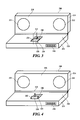
- FIG. 2 is a view corresponding to FIG. 1 in a second configuration
- FIG. 3 is a front perspective view of a second embodiment in a first configuration
- FIG. 4 is a view corresponding to FIG. 2 in a second configuration
- FIG. 5 is a front perspective view of a third embodiment in a first configuration
- FIG. 6 is a view corresponding to FIG. 5 with an audio player operatively attached
- FIG. 7 is a front perspective view of a fourth embodiment in a first configuration
- FIG. 8 is a view corresponding to FIG. 7 in a second configuration
- FIG. 9 is a vertical cross-section along the lines and in the direction of arrows 9 - 9 in FIG. 8 ;
- FIG. 10 is a vertical cross-section along the lines and in the direction of arrows 10 - 10 in FIG. 7 ;
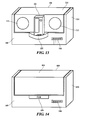
- FIG. 11 is a view corresponding to FIG. 7 of a fifth embodiment
- FIG. 12 is a view corresponding to FIG. 8 of the fifth embodiment
- FIG. 13 is a view corresponding to FIG. 12 with an audio player attached
- FIG. 14 is a view corresponding to FIG. 7 of a sixth embodiment.
- FIG. 15 is a view corresponding to FIG. 8 of the sixth embodiment.
- FIGS. 1 and 2 there is shown a first embodiment of portable speakers 100 .
- FIG. 1 it is in a first configuration—a closed or not-in-use configuration.
- FIG. 2 it is in the second configuration—are open or in-use configuration.
- the portable speakers 100 comprise at least one loud speaker or driver 112 (hereinafter “driver”). There may be any required number of drivers 112 . In this case there are two drivers.
- the drivers 112 are preferably spaced apart to provide a stereophonic effect, and are mounted in or to a first surface 116 of a first or driver enclosure 114 .
- the drivers 112 are mounted to first surface 116 such that they are either flush with surface 116 or are recessed into surface 116 . They should not project outwardly beyond surface 116 .
- Surface 116 may be planar and flat.
- the first enclosure 114 is separate from but pivotally mounted to a second or electronics enclosure 124 by means of one or more hinges 122 .
- the separation includes acoustic separation. All electronic components including but not limited to:
- the second enclosure 124 has an upper surface 126 that is preferably the same size and shape as first surface 116 , and also may be planar and flat. In this way the first enclosure 114 can be pivoted about hinges 122 until first surface 116 overlays and is immediately adjacent to or contacts upper surface 126 thereby enabling the second enclosure 124 to protect drivers 112 when the portable speakers 100 are not in use and in the first configuration.
- the hinge 122 may be any suitable form of hinge or hinges including a spring hinge to bias the first enclosure to the second or open configuration, piano hinge, or the like.
- the hinge 122 may also act as a switch such that moving the first enclosure 114 away from the second enclosure 214 from the first configuration towards the second configuration may turn on the speakers 100 .
- All electrical connections between the first enclosure 114 and the second enclosure 124 may be by a cable (not shown) that may pass through hinge 122 .
- the cable may be of any suitable form including co-axial, flat, or the like.
- drivers 112 are protected when not in use, but all electronic components, source for power such as batteries, controls 146 , and the like, are physically and acoustically separated from the drivers 112 to thus reduce induced vibration and thus distortion, and unwanted microphonic effects.
- a mechanical stop may be provided to prevent first enclosure 114 pivoting excessively relative to second enclosure 124 .
- the first surface is at an included angle relative to the upper surface that is in the range 90° to 120°.
- the centre of gravity of the first compartment may be outside the periphery of the second compartment so that it will not tend to close when the speaker 100 is in use.
- the second enclosure 124 also acts as a stable base for the first enclosure 114 with the enclosed electronics and batteries providing, at least in part, the necessary weight to lower the position of the centre of gravity and, correspondingly, improve the stability of the speakers 100 .
- a dampening material such as, for example, rubber, may be placed between hinge 122 and first enclosure 114 and/or second enclosure 124 .
- the second embodiment of FIGS. 3 and 4 is for a portable speaker 200 and is substantially the same as the first embodiment 100 .
- the principal difference is the addition of a pivoting connector 228 .
- the mounting of the connector 228 is in recess 230 and is relative to upper surface 226 is such that when connector 228 is in the first (non-use) configuration of FIG. 3 , its top surface 232 is flush with or below upper surface 226 .
- a jack 234 that forms part of pivoting connector 228 extends upwardly from upper surface 226 .
- the jack 234 is preferably a headphone jack (as illustrated) to enable it to directly engage a headphone port in an audio player/module, or other form of media player, (not shown).
- a port or a receptor may be incorporated into connector 228 for the connection of the audio player/module.
- the pivoting connector 228 and its recess 230 are located in upper surface 226 between the drivers 212 such that if the first enclosure 21 is mounted to the first (closed) configuration, the pivoting connector 228 will not damage the drivers 212 .
- the portable speakers 300 of the third embodiment of FIGS. 5 and 6 are substantially the same as the second embodiment 200 except that jack 234 is replaced by a multiple-pin connection 336 such as, for example, a USB, IEEE1394, or custom multiple-pin connection.
- a multiple-pin connection 336 such as, for example, a USB, IEEE1394, or custom multiple-pin connection.
- an audio player 302 can be directly mounted to connection 336 both physically and electrically.
- the portable speakers 400 of the fourth embodiment are shown in FIGS. 7 to 10 .
- the first enclosure 414 is pivotally mounted to and within second enclosure 424 by means of pivot pins 418 extending outwardly from the ends 420 of first enclosure 414 , the pivot pins 418 engaging extended side walls 438 of second enclosure 424 .
- the pivot pins 418 may extend inwardly from side walls 438 and engage ends 420 of first enclosure 414 .
- the two exposed side surfaces 415 , and 417 of first enclosure 414 are substantially flush or co-planar with their corresponding surfaces 440 , and 442 of second enclosure 424 .
- the two exposed side surfaces 416 and 415 of first enclosure 414 are substantially flush or co-planar with their corresponding surfaces 440 , and 442 of second enclosure 424 .
- drivers 412 when in the use or second configuration, face outwardly. They may face upwardly, or at an incline, if desired or required.
- the upper surface 426 of second enclosure is concave along its length to allow for the pivoting movement of the first enclosure 414 .
- electrical connections to drivers 412 from the second enclosure 424 are through cables passing through one or both pivot pins 418 .
- the drivers 412 are protected when in the first, or non-use configuration, and a pivoting movement of 90 degrees is required to move the drivers 412 to a second or in-use position.
- the electronics 448 , battery compartment 450 and controls 446 are located in the second enclosure and the drivers 412 are in the first enclosure, again to reduce microphonics, and the second enclosure 424 acts as a stable base for the first enclosure 414 .
- the fifth embodiment of portable speakers 500 of FIGS. 11 to 13 is substantially the same as the fourth embodiment 400 with the principal difference being the addition of a pivoting connector 528 in front surface 540 of second enclosure 524 .
- the connector 528 pivots about one or more vertical pivot pins (not shown) between a first or non-use position of FIG. 11 to a second or in-use position of FIGS. 12 and 13 .
- the connector 528 includes a connection 536 that may be a USB, IEEE1394, or custom multiple-pin connection (as shown), jack, or the like.
- the connection 536 is to enable a direct physical and electrical connection by the audio player, or other media player 502 , ( FIG. 13 ). When in the non-use position, end 532 of connector 528 is flush with front surface 540 .
- the sixth embodiment of portable speakers 600 of FIGS. 14 and 15 is the same as the of the fifth embodiment 500 except that the connector 628 has a sliding mounting in and relative to front surface 640 . Preferably, it is a “push-to-engage, push-to-release” mounting.
Abstract
Description
-
- (a) a source for power such as a battery compartment for the required battery or batteries/capacitors and/or a connection for mains power,
- (b) a connection for operative connection to an audio source, and
- (c) controls 146 for the
portable speakers 100,
are mounted in or tosecond enclosure 124. Thecontrols 146 may control only functions of thespeakers 100, or may also include controls for the audio source.
Claims (15)
Priority Applications (6)
| Application Number | Priority Date | Filing Date | Title |
|---|---|---|---|
| US11/144,879 US8050441B2 (en) | 2005-06-03 | 2005-06-03 | Portable speakers |
| GB0723346A GB2441089B (en) | 2005-06-03 | 2006-05-15 | A portable speaker with separate enclosures |
| CNA2006800195573A CN101204117A (en) | 2005-06-03 | 2006-05-15 | Portable speakers with separate enclosures |
| DE112006001411T DE112006001411T5 (en) | 2005-06-03 | 2006-05-15 | Portable speaker with separate enclosures |
| PCT/SG2006/000122 WO2006130114A1 (en) | 2005-06-03 | 2006-05-15 | Portable speakers with separate enclosures |
| TW095117452A TWI407803B (en) | 2005-06-03 | 2006-05-17 | Portable speaker with separate enclosures |
Applications Claiming Priority (1)
| Application Number | Priority Date | Filing Date | Title |
|---|---|---|---|
| US11/144,879 US8050441B2 (en) | 2005-06-03 | 2005-06-03 | Portable speakers |
Publications (2)
| Publication Number | Publication Date |
|---|---|
| US20060274912A1 US20060274912A1 (en) | 2006-12-07 |
| US8050441B2 true US8050441B2 (en) | 2011-11-01 |
Family
ID=37481947
Family Applications (1)
| Application Number | Title | Priority Date | Filing Date |
|---|---|---|---|
| US11/144,879 Expired - Fee Related US8050441B2 (en) | 2005-06-03 | 2005-06-03 | Portable speakers |
Country Status (6)
| Country | Link |
|---|---|
| US (1) | US8050441B2 (en) |
| CN (1) | CN101204117A (en) |
| DE (1) | DE112006001411T5 (en) |
| GB (1) | GB2441089B (en) |
| TW (1) | TWI407803B (en) |
| WO (1) | WO2006130114A1 (en) |
Cited By (6)
| Publication number | Priority date | Publication date | Assignee | Title |
|---|---|---|---|---|
| US20130050933A1 (en) * | 2008-09-05 | 2013-02-28 | Apple Inc. | Docking station with moveable connector for hand held electronic device |
| US20140281096A1 (en) * | 2013-03-14 | 2014-09-18 | G-Tek Electronics Corporation | Broadcasting device with communication mechanism |
| USD754092S1 (en) * | 2014-07-11 | 2016-04-19 | Harman International Industries, Incorporated | Portable loudspeaker |
| US20160127830A1 (en) * | 2009-12-31 | 2016-05-05 | Slotius, Llc | Self-powered audio speaker having socket for audio data receiver |
| US20170371372A1 (en) * | 2016-06-23 | 2017-12-28 | Microsoft Technology Licensing, Llc | User Input Peripheral |
| US20170374462A1 (en) * | 2016-06-23 | 2017-12-28 | Microsoft Technology Licensing, Llc | Peripheral Device Transducer Configuration |
Families Citing this family (7)
| Publication number | Priority date | Publication date | Assignee | Title |
|---|---|---|---|---|
| KR100694158B1 (en) * | 2005-11-26 | 2007-03-12 | 삼성전자주식회사 | Portable speaker device used for portable multimedia device |
| WO2007079478A2 (en) * | 2006-01-04 | 2007-07-12 | Coby Electronics Corporation | Portable speaker device and portable audio device player |
| KR100804745B1 (en) * | 2006-08-23 | 2008-02-19 | 이유준 | Attachable speaker having composite function |
| JP2011239335A (en) * | 2010-05-13 | 2011-11-24 | Hiroyuki Yamagami | Acoustic unit |
| US20120250875A1 (en) * | 2011-03-31 | 2012-10-04 | Nicholson Travis E | Portable Loudspeaker |
| JP5168385B2 (en) * | 2011-05-11 | 2013-03-21 | 株式会社Jvcケンウッド | Electronics |
| US20140064538A1 (en) * | 2012-09-05 | 2014-03-06 | Stelle LLC | Clutch speaker |
Citations (7)
| Publication number | Priority date | Publication date | Assignee | Title |
|---|---|---|---|---|
| US4139734A (en) | 1977-04-13 | 1979-02-13 | Kef Electronics Limited | Pivoted loudspeaker enclosure with visual indicator of optimum listening position |
| US4441577A (en) | 1981-10-30 | 1984-04-10 | Clarion Co., Ltd | Direction-variable speaker system |
| US4932060A (en) | 1987-03-25 | 1990-06-05 | Bose Corporation | Stereo electroacoustical transducing |
| US5349575A (en) * | 1992-05-19 | 1994-09-20 | Goldstar Co., Ltd. | Portable audio device |
| US6392871B1 (en) * | 1997-10-30 | 2002-05-21 | Nec Corporation | Portable computer system with adjustable display subsystem |
| US20050248911A1 (en) | 2004-05-06 | 2005-11-10 | Creative Technology Ltd. | Multimedia speaker with integrated stand |
| US7095867B2 (en) * | 2004-04-30 | 2006-08-22 | Altec Lansing Technologies, Inc. | Portable audio reproduction system |
Family Cites Families (3)
| Publication number | Priority date | Publication date | Assignee | Title |
|---|---|---|---|---|
| TWM266625U (en) * | 2004-09-24 | 2005-06-01 | Ming-Shiang Ye | Connector |
| TWM262776U (en) * | 2004-10-08 | 2005-04-21 | Hannspree Inc | Display and electric connection structure thereof |
| CN101142845B (en) * | 2005-03-08 | 2011-05-25 | Nxp股份有限公司 | Loudspeaker enclosure with a closed and an open position |
-
2005
- 2005-06-03 US US11/144,879 patent/US8050441B2/en not_active Expired - Fee Related
-
2006
- 2006-05-15 GB GB0723346A patent/GB2441089B/en not_active Expired - Fee Related
- 2006-05-15 CN CNA2006800195573A patent/CN101204117A/en active Pending
- 2006-05-15 WO PCT/SG2006/000122 patent/WO2006130114A1/en active Application Filing
- 2006-05-15 DE DE112006001411T patent/DE112006001411T5/en not_active Withdrawn
- 2006-05-17 TW TW095117452A patent/TWI407803B/en active
Patent Citations (7)
| Publication number | Priority date | Publication date | Assignee | Title |
|---|---|---|---|---|
| US4139734A (en) | 1977-04-13 | 1979-02-13 | Kef Electronics Limited | Pivoted loudspeaker enclosure with visual indicator of optimum listening position |
| US4441577A (en) | 1981-10-30 | 1984-04-10 | Clarion Co., Ltd | Direction-variable speaker system |
| US4932060A (en) | 1987-03-25 | 1990-06-05 | Bose Corporation | Stereo electroacoustical transducing |
| US5349575A (en) * | 1992-05-19 | 1994-09-20 | Goldstar Co., Ltd. | Portable audio device |
| US6392871B1 (en) * | 1997-10-30 | 2002-05-21 | Nec Corporation | Portable computer system with adjustable display subsystem |
| US7095867B2 (en) * | 2004-04-30 | 2006-08-22 | Altec Lansing Technologies, Inc. | Portable audio reproduction system |
| US20050248911A1 (en) | 2004-05-06 | 2005-11-10 | Creative Technology Ltd. | Multimedia speaker with integrated stand |
Non-Patent Citations (3)
| Title |
|---|
| Operating Instructions, "Sony SRS-T57 Active Speaker System" © 2004. |
| Operating Instructions, "Sony SRS-T77 Active Speaker System" © 2000. |
| U.S. Appl. No. 10/907,468, Goh |
Cited By (9)
| Publication number | Priority date | Publication date | Assignee | Title |
|---|---|---|---|---|
| US20130050933A1 (en) * | 2008-09-05 | 2013-02-28 | Apple Inc. | Docking station with moveable connector for hand held electronic device |
| US20160127830A1 (en) * | 2009-12-31 | 2016-05-05 | Slotius, Llc | Self-powered audio speaker having socket for audio data receiver |
| US20140281096A1 (en) * | 2013-03-14 | 2014-09-18 | G-Tek Electronics Corporation | Broadcasting device with communication mechanism |
| USD754092S1 (en) * | 2014-07-11 | 2016-04-19 | Harman International Industries, Incorporated | Portable loudspeaker |
| US20170371372A1 (en) * | 2016-06-23 | 2017-12-28 | Microsoft Technology Licensing, Llc | User Input Peripheral |
| US20170374462A1 (en) * | 2016-06-23 | 2017-12-28 | Microsoft Technology Licensing, Llc | Peripheral Device Transducer Configuration |
| US10015594B2 (en) * | 2016-06-23 | 2018-07-03 | Microsoft Technology Licensing, Llc | Peripheral device transducer configuration |
| US10334364B2 (en) * | 2016-06-23 | 2019-06-25 | Microsoft Technology Licensing, Llc | Transducer control based on position of an apparatus |
| CN112256093A (en) * | 2016-06-23 | 2021-01-22 | 微软技术许可有限责任公司 | Clamshell peripheral device with open-close detection |
Also Published As
| Publication number | Publication date |
|---|---|
| US20060274912A1 (en) | 2006-12-07 |
| TW200708165A (en) | 2007-02-16 |
| TWI407803B (en) | 2013-09-01 |
| CN101204117A (en) | 2008-06-18 |
| GB0723346D0 (en) | 2008-01-09 |
| GB2441089A (en) | 2008-02-20 |
| DE112006001411T5 (en) | 2008-04-30 |
| GB2441089B (en) | 2010-02-03 |
| WO2006130114A1 (en) | 2006-12-07 |
Similar Documents
| Publication | Publication Date | Title |
|---|---|---|
| US8050441B2 (en) | Portable speakers | |
| US20130163186A1 (en) | Connection unit and electronic apparatus | |
| US8481832B2 (en) | Docking station system | |
| KR20090050834A (en) | Cradle for portable terminal | |
| GB2451894A (en) | Two-part dock for an MP3 device, including a base unit housing low frequency bass speaker | |
| US7738241B2 (en) | Auxiliary mounting device capable of guiding an audio output from an electronic device | |
| WO2015027500A1 (en) | Mini-speaker | |
| WO2015027499A1 (en) | Mini-speaker | |
| WO2015027503A1 (en) | Mini-speaker | |
| WO2007086117A1 (en) | Electronic apparatus | |
| US10791393B2 (en) | Speaker case for a mobile device and speaker system with such a speaker case | |
| US20060210105A1 (en) | Combined computer mouse and speaker device | |
| CN101754606B (en) | Electronic device | |
| US10606309B2 (en) | Notebook computer | |
| US8504182B2 (en) | Media player | |
| US20150146370A1 (en) | Cover | |
| JP2006012187A (en) | Desktop computer | |
| JP2004135119A (en) | Cradle of portable digital assistant, and cradle connection method | |
| GB2516752A (en) | Electric device | |
| JP2005100043A (en) | Information equipment | |
| US10805700B2 (en) | Expansion device having a speaker | |
| US20070236868A1 (en) | Audio reproduction device assembly adapted for use with a portable rechargable audio playback device | |
| KR200404505Y1 (en) | Portable computer with rotary speaker unit | |
| JP4082055B2 (en) | Information processing unit with built-in speaker unit | |
| CN218450392U (en) | Lamp plate fixed knot constructs audio amplifier |
Legal Events
| Date | Code | Title | Description |
|---|---|---|---|
| AS | Assignment |
Owner name: CREATIVE TECHNOLOGY LTD., SINGAPORE Free format text: ASSIGNMENT OF ASSIGNORS INTEREST;ASSIGNORS:TAN, JENG KHIM;ANG, HUANG PHENG;GOH, AIK HEE;AND OTHERS;SIGNING DATES FROM 20050531 TO 20050601;REEL/FRAME:016664/0663 Owner name: CREATIVE TECHNOLOGY LTD., SINGAPORE Free format text: ASSIGNMENT OF ASSIGNORS INTEREST;ASSIGNORS:TAN, JENG KHIM;ANG, HUANG PHENG;GOH, AIK HEE;AND OTHERS;REEL/FRAME:016664/0663;SIGNING DATES FROM 20050531 TO 20050601 |
|
| ZAAA | Notice of allowance and fees due |
Free format text: ORIGINAL CODE: NOA |
|
| ZAAB | Notice of allowance mailed |
Free format text: ORIGINAL CODE: MN/=. |
|
| ZAAA | Notice of allowance and fees due |
Free format text: ORIGINAL CODE: NOA |
|
| STCF | Information on status: patent grant |
Free format text: PATENTED CASE |
|
| FPAY | Fee payment |
Year of fee payment: 4 |
|
| FEPP | Fee payment procedure |
Free format text: ENTITY STATUS SET TO SMALL (ORIGINAL EVENT CODE: SMAL); ENTITY STATUS OF PATENT OWNER: SMALL ENTITY |
|
| MAFP | Maintenance fee payment |
Free format text: PAYMENT OF MAINTENANCE FEE, 8TH YR, SMALL ENTITY (ORIGINAL EVENT CODE: M2552); ENTITY STATUS OF PATENT OWNER: SMALL ENTITY Year of fee payment: 8 |
|
| FEPP | Fee payment procedure |
Free format text: MAINTENANCE FEE REMINDER MAILED (ORIGINAL EVENT CODE: REM.); ENTITY STATUS OF PATENT OWNER: SMALL ENTITY |
|
| LAPS | Lapse for failure to pay maintenance fees |
Free format text: PATENT EXPIRED FOR FAILURE TO PAY MAINTENANCE FEES (ORIGINAL EVENT CODE: EXP.); ENTITY STATUS OF PATENT OWNER: SMALL ENTITY |
|
| STCH | Information on status: patent discontinuation |
Free format text: PATENT EXPIRED DUE TO NONPAYMENT OF MAINTENANCE FEES UNDER 37 CFR 1.362 |
|
| FP | Lapsed due to failure to pay maintenance fee |
Effective date: 20231101 |