US8055179B2 - Image forming apparatus, method therefor, and program - Google Patents
Image forming apparatus, method therefor, and program Download PDFInfo
- Publication number
- US8055179B2 US8055179B2 US12/273,656 US27365608A US8055179B2 US 8055179 B2 US8055179 B2 US 8055179B2 US 27365608 A US27365608 A US 27365608A US 8055179 B2 US8055179 B2 US 8055179B2
- Authority
- US
- United States
- Prior art keywords
- image forming
- image
- processing
- unit
- sides
- Prior art date
- Legal status (The legal status is an assumption and is not a legal conclusion. Google has not performed a legal analysis and makes no representation as to the accuracy of the status listed.)
- Expired - Fee Related, expires
Links
Images


Classifications
-
- G—PHYSICS
- G03—PHOTOGRAPHY; CINEMATOGRAPHY; ANALOGOUS TECHNIQUES USING WAVES OTHER THAN OPTICAL WAVES; ELECTROGRAPHY; HOLOGRAPHY
- G03G—ELECTROGRAPHY; ELECTROPHOTOGRAPHY; MAGNETOGRAPHY
- G03G15/00—Apparatus for electrographic processes using a charge pattern
- G03G15/22—Apparatus for electrographic processes using a charge pattern involving the combination of more than one step according to groups G03G13/02 - G03G13/20
- G03G15/23—Apparatus for electrographic processes using a charge pattern involving the combination of more than one step according to groups G03G13/02 - G03G13/20 specially adapted for copying both sides of an original or for copying on both sides of a recording or image-receiving material
- G03G15/231—Arrangements for copying on both sides of a recording or image-receiving material
- G03G15/232—Arrangements for copying on both sides of a recording or image-receiving material using a single reusable electrographic recording member
- G03G15/234—Arrangements for copying on both sides of a recording or image-receiving material using a single reusable electrographic recording member by inverting and refeeding the image receiving material with an image on one face to the recording member to transfer a second image on its second face, e.g. by using a duplex tray; Details of duplex trays or inverters
Definitions
- the present invention relates to an image forming apparatus, capable of performing both-sides printing on a recording sheet, a method therefor, and a program.
- a both-sides printing method is known that as an initial step, an image is formed on the first surface of each of some recording sheets and thereafter as a subsequent step, an image is alternately formed on the first surface of a recording sheet and second surface of a recording sheet (for example, see, U.S. Pat. No. 4,935,786).
- an image forming apparatus capable of connecting to various kinds of post-processing apparatuses.
- a processing capacity for each of the post-processing apparatuses per unit time is made higher than an image forming capability of the image forming apparatus so as to prevent the image forming apparatus from being kept waiting for an image forming processing thereof.
- the post-processing apparatus is made to have a capability half of or more than half of an image forming capability of the image forming apparatus in a one-side printing mode so as to substantially prevent the image forming apparatus from being kept waiting for the image forming processing thereof.
- the image forming apparatus is required to improve image quality for the both-sides printing thereof, and a problem is pointed out that images formed on the first and second surfaces have different sizes from each other because a recording sheet shrinks during thermal fixing performed along with the image formation on the first surface of the recording sheet.
- a method is proposed to switch a rotational speed of a polygon mirror for the image formation between the first and second surfaces (for example, see, U.S. Pat. No. 6,839,078).
- a high-speed image forming apparatus requiring high-quality images needs to have a configuration to change the rotational speed of the polygon mirror during the both-sides printing.
- it needs a lot of time to change the rotational speed of the polygon mirror because the polygon mirror is made to have a large inertia to stably rotate at a high speed.
- it is necessary to perform a speed-changing processing of the polygon mirror at every such occasion, thereby making the image forming processing itself of the image forming apparatus becomes slower.
- This problem can be solved by performing the image formation on the first surfaces of a plurality of sheets at one time and subsequently performing the image formation on the second surfaces at one time instead of alternately performing the image formation on the first and second surfaces. This is because, if such configuration is employed, the rotational speed of the polygon mirror changes for less number of times, the image forming apparatus can reduce a time period for the image forming processing.
- the image forming apparatus having the configuration as described above successively performs the image formation on the second surfaces of the plurality of recording sheets. Accordingly, in a case where a post-processing is performed by a post-processing apparatus having a processing capability half of a processing capability of the image forming apparatus in a one-side printing mode, the post-processing apparatus may cause the image forming apparatus to be kept waiting for the image forming processing thereof. In addition, it becomes necessary for the post-processing apparatus to be provided with a buffer for storing the recording sheets so that the post-processing can be done while the image forming apparatus is performing the image formation on the first surfaces.
- the number of the sheets for image formation per unit time may sometimes be reduced so that a fixing unit can apply sufficient heat to the thick sheet.
- the present invention is made in consideration of the above problems, and provides an image forming apparatus capable of efficiently performing an image forming processing even in a case where a post-processing apparatus performs a post-processing during a both-sides printing, a method therefor, and a program.
- an image forming apparatus comprising a first feeding unit adapted to feed a recording sheet from a container containing the recording sheet, an image forming unit adapted to form an image on the recording sheet, a second feeding unit adapted to re-feed to the image forming unit the recording sheet having the image formed on a first surface thereof by the image forming unit so that an image is formed on a second surface opposite to the first surface, a post-processing unit adapted to perform a post-processing on the recording sheet having an image formed thereon, a both-sides image formation control unit adapted to perform either of a first both-sides image forming processing or a second both-sides image forming processing by controlling the image forming unit, the first feeding unit, and the second feeding unit, wherein the first both-sides image forming processing controls, for at least one time, the first feeding unit to successively feed a plurality of recording sheets, and the image forming unit to successively form an image on the first surface of each of
- the present invention enables efficiently performing the image forming processing even in a case where the post-processing apparatus performs the post-processing during the both-sides printing.
- FIG. 1 is a functional block diagram showing a digital printing machine as an example of an image forming apparatus according to an embodiment of the present invention.
- FIG. 2 is a longitudinal sectional view showing an internal structure of the digital printing machine of FIG. 1 .
- FIG. 3 is a schematic structural diagram of a laser scanner shown in FIG. 2 .
- FIG. 4 is a diagram useful in explaining a polygon mirror rotational speed control using a BD sensor shown in FIG. 3 .
- FIG. 5 is a diagram useful in explaining a change of a laser scanning control based on a shrink of a recording sheet.
- FIG. 6 is a view illustrating an initial conveyance state of recording sheets in a block circulation in the digital printing machine.
- FIG. 7 is a view illustrating a middle-period conveyance state of the recording sheets in the block circulation in the digital printing machine.
- FIG. 8 is a view illustrating a later-period conveyance state of the recording sheets in the block circulation in the digital printing machine.
- FIG. 9 is a view showing a series of recording sheets subjected to image formation during the block circulation.
- FIG. 10 is a view showing an initial conveyance state of recording sheets in an alternate circulation in the digital printing machine.
- FIG. 11 is a view showing a middle-period conveyance state of the recording sheets in the alternate circulation in the digital printing machine.
- FIG. 12 is a view showing a later-period conveyance state of the recording sheets in the alternate circulation in the digital printing machine.
- FIG. 13 is a view showing a series of recording sheets subjected to image formation during the alternate circulation.
- FIGS. 14A and 14B are views showing an image forming interval in a both-sides image forming sequence of the printing machine itself.
- FIG. 14A shows a case of the block circulation.
- FIG. 14B shows a case of the alternate circulation.
- FIG. 15 is a view showing an image forming interval and recording sheets in the block circulation.
- FIG. 16 is a view showing an image forming interval and recording sheets in the alternate circulation.
- FIG. 17 is a flowchart showing a procedure of a selection processing of the both-sides image forming sequence.
- FIG. 18 is a diagram useful in explaining a calculation method for obtaining a time period needed for the block circulation.
- FIG. 19 is a diagram useful in explaining a calculation method for obtaining a time period needed for the alternate circulation.
- FIGS. 20A and 20B are views showing an example of a case where a required image forming interval becomes less due to a post-processing operation.
- FIG. 20A shows a case of the block circulation.
- FIG. 20B shows a case of the alternate circulation.
- FIG. 21 is a view showing an influence exerted by the change of the polygon mirror rotational speed during a down sequence control in a case where the image formation is switched from the first surface (a front surface) to the second surface (a back surface).
- FIG. 1 is a functional block diagram showing a digital printing machine as an example of an image forming apparatus according to an embodiment of the present invention.
- a numeral 101 denotes a CPU performing all controls of the digital printing machine
- a numeral 102 denotes a ROM storing control content to be executed by the CPU 101 and a data to be controlled thereby
- a numeral 103 denotes a RAM used as a work area needed for the CPU 101 to control the digital printing machine.
- the RAM 103 is used not only as the work area for the CPU 101 but also as a work area for allowing an image processing unit 107 to perform an image processing on digital image data obtained via an external I/F 106 .
- the digital image subjected to image processing in the image processing unit 107 is compressed and stored in an HOD 104 .
- a numeral 105 denotes an operation unit for configuring a print job which an operator wants to execute on the digital printing machine.
- a later-described post-processing can be configured with the operation unit 105 .
- the external I/F 106 is connected to a network based on TCP/IP and the like.
- a computer (not shown) connected to the network transmits an execution instruction of the print job and obtains information such as a remaining amount of a consumable and the like via the external I/P 106 .
- the image processing unit 107 performs the required image processing on the digital image data received via the external I/F 106 , and stores the digital image data to the HDD 104 .
- the image processing unit 107 reads the digital image data from the HDD 104 , and performs a processing to expand the digital image data on the RAM 103 upon performing a predetermined image processing on the digital image data having been read out.
- an image forming unit 108 forms a toner image derived from the digital image data expanded on the RAM 103 .
- a toner supply unit 109 supplies, from a toner bottle (not shown), toner to be consumed by the image forming unit 108 .
- a sheet feeding unit 110 feeds a recording sheet contained in the digital printing machine, and subsequently, a conveyance unit 111 conveys the recording sheet to the image forming unit 108 . Then, the toner image formed by the image forming unit 108 is transferred onto the recording sheet.
- the recording sheet may also be referred to as a sheet, a recording medium, and paper.
- a fixing unit 112 fixes the toner image having been transferred on the recording sheet, and the recording sheet is conveyed toward a post-processing unit 113 .
- the recording sheet is conveyed toward the image forming unit 108 via the conveyance unit 111 .
- the post-processing unit 113 performs a post-processing, based on the configuration of the print job, on the recording sheet having the image formed thereon.
- the post-processing can involve, for example, a stapling processing for binding a corner of a bundle of recording sheets with a staple, a punching processing for punching holes on each end portion of the recording sheets, a center-binding processing for binding a central portion of a bundle of recording sheets and folding the recording sheets into two.
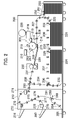
- FIG. 2 is a longitudinal sectional view showing an internal structure of the digital printing machine of FIG. 1 .
- a numeral 200 denotes a main body of the digital printing machine
- a numeral 250 denotes a side sheet deck.
- a numeral 210 denotes a laser scanner made up with a laser, a polygon mirror, and the like. The laser scanner 210 emits to a photosensitive drum 211 , serving as an image bearing member, a laser light 219 modulated based on an image signal generated through an predetermined image processing performed on image information such as the digital image data and the like contained in the RAM 103 and the HDD 104 by the image processing unit 107 .
- a first charging device 212 , a developing device 213 , a transfer charging device 214 , a separation charging device 215 , a cleaning apparatus 216 , and a pre-exposure lamp 217 are arranged around the photosensitive drum 211 .
- the photosensitive drum 211 is rotated by a motor, not shown, in a direction of an arrow indicated in FIG. 2 .
- the laser scanner 210 emits the laser light 219 to the surface of the photosensitive drum 211 , so that a latent image is formed on the surface of the photosensitive drum 211 .
- the latent image formed on the photosensitive drum 211 is developed by the developing device 213 and becomes visible as a toner image.
- a toner sensor not shown, in the developing device 213 detects that the developing device 213 runs out of toner, the toner is supplied from a toner buffer 218 to the developing device 213 .
- a motor rotates the toner bottle 220 to cause the toner contained in the toner bottle 220 to be dropped into the toner buffer 218 , so that the toner is supplied to the toner buffer 218 .
- the toner sensor detects that there remains only a little toner in the toner buffer 218 even where the toner bottle is rotated for a predetermined time, a message to the effect that it is necessary to replace the toner bottle is notified to an operator via the operation unit 105 .
- the recording sheet fed with a pickup roller 222 from a right deck 221 is forwarded with feeding rollers 223 to a main conveyance path 227 .
- the recording sheet contained in a left deck 224 is fed with a pickup roller 225 and is forwarded with feeding rollers 226 to the main conveyance path 227 via a re-feeding path 238 .
- the recording sheet contained in a side sheet deck 250 is fed with a pickup roller 251 and is forwarded with feeding rollers 252 to the main conveyance path 227 .
- the right deck 221 , the left deck 224 , the side sheet deck 250 , the pickup rollers 222 , 225 , 251 , the feeding rollers 223 , 226 , 252 , and motors (not shown) for diving each roller correspond to the feeding unit 110 shown in FIG. 1 .
- the recording sheet forwarded to the main conveyance path 227 is forwarded with registration rollers 228 to a transfer unit, and the transfer charging device 214 transfers the toner image formed on the photosensitive drum 211 onto the recording sheet.
- the cleaning apparatus 216 cleans residual toner from the photosensitive drum 211 , and the pre-exposure lamp 217 erases residual electric charge.
- the recording sheet having the toner image transferred thereon is separated by the separation charging device 215 from the photosensitive drum 211 , and is conveyed by a conveyance belt 229 to the fixing device 230 directly.
- the recording sheet forwarded to the fixing device 230 is applied with pressure and heat, so that the toner image transferred thereon is fixed.
- the recording sheet is conveyed to an external sheet discharging path 233 via internal sheet discharging rollers 231 , and is discharged out of the digital printing machine 200 .
- the laser scanner 210 , the first charging device 212 , the developing device 213 , the transfer charging device 214 , the separation charging device 215 , the cleaning apparatus 216 , the pre-exposure lamp 217 , and the like arranged around the photosensitive drum 211 correspond to the image forming unit 108 shown in FIG. 1 .
- a sheet discharging flapper 232 switches a path between a reversing path 234 and an external sheet discharging path 233 .
- the recording sheet can be reversed and discharged out of the apparatus by switching a tip of the sheet discharging flapper 232 to the upper side, conveying the recording sheet having passed through the fixing device 230 into the reversing path 234 , and thereafter immediately rotating a roller on the path in an opposite direction to convey the recording sheet to the external sheet discharging path 233 .
- the recording sheet conveyed into the reversing path 234 is conveyed into a both-sides reversing path 235 .
- a both-sides flapper 236 is switched, and a roller on the both-sides reversing path 235 is rotated in an opposite direction, so that the recording sheet is reversed and is conveyed to a lower conveyance path 237 .
- a conveyance speed of the recording sheet in the reversing path 234 , the both-sides reversing path 235 , and the lower conveyance path 237 is set to be twice as fast as a conveyance speed for conveying the recording sheet around the fixing device 230 .
- an interval between recording sheets is narrower when the recording sheet passes through the fixing device 230 .
- the recording sheet is conveyed at a faster speed to increase the interval between sheets, so that the recording sheet can be successively conveyed into the lower conveyance path 237 .
- the recording sheet conveyed to the lower conveyance path 237 is conveyed to the re-feeding path 238 directly, and is further conveyed by way of the main conveyance path 227 , and a toner image is transferred onto the second surface in the both-sides printing.
- rollers, flappers, driving motors therefor, and the like arranged on the main conveyance path 227 , the reversing path 234 , the both-sides reversing path 235 , the lower conveyance path 237 , and the external sheet discharging path 233 correspond to the conveyance unit 111 shown in FIG. 1 .
- a numeral 270 denotes a finisher for aligning and stacking the recording sheet discharged out of the digital printing machine 200 .
- the recording sheet discharged sheet by sheet out of the external sheet discharging path 233 of the digital printing machine 200 is discharged to either of the sheet discharging trays 274 , 280 , 285 .
- the finisher 270 corresponds to the post-processing unit 113 shown in FIG. 1 .
- the sheet discharging trays 274 , 280 can be moved up and down by a motor, not shown. Especially, the sheet discharging tray 274 can be lowered as low as a position of a processing tray 278 .
- a position of the sheet discharging tray may be lowered, so that a position of a top sheet surface on the sheet discharging tray is aligned with a sample tray path 273 or the processing tray 278 .
- This finisher 270 can perform the post-processing, i.e., the punching processing, the stapling processing, and the center-binding processing.
- a punching unit 271 punches holes on the recording sheet conveyed to the finisher 270 via the external sheet discharging path 233 . Thereafter, a sample sheet discharging flapper 272 switches between the sample tray path 273 and a processing tray path 275 . In a case where the recording sheet is conveyed to the sample tray path 273 , the recording sheet is discharged to the sheet discharging tray 274 directly.
- a saddle flapper 276 switches a path therebeyond to either of the processing tray path 277 or a saddle path 281 .
- the recording sheet is discharged to the processing tray 278 , and a stapling unit 279 executes the desired stapling processing according to a stapling specification for the recording sheet when a bundle of recording sheets gets together. Thereafter, when the processing is completed, the recording sheet is discharged to the previously specified sheet discharging tray 274 or the sheet discharging tray 280 .
- a stapling unit binds a center of the recording sheet conveyed to the saddle path 281 when a bundle of recording sheets gets together.
- a thrusting unit 282 thrusts the central portion of the bundle of recording sheets toward a left direction in FIG. 2 , and the bundle of recording sheets is folded into two at the central portion with folding rollers 283 , so that the bundle of recording sheets is bound into a book.
- the folded book bundle is discharged through a binding path 284 to the saddle discharging tray 285 .
- FIG. 3 is a schematic structural diagram of the laser scanner 210 shown in FIG. 2 .
- FIG. 4 is a diagram useful in explaining a polygon mirror rotational speed control using a BD sensor shown in FIG. 3 .
- FIG. 5 is a diagram useful in explaining a change of a laser scanning control based on a shrink of a recording sheet.
- the laser light emitted from a semiconductor laser 301 is shaped by a collimator lens (not shown) and a cylindrical lens 302 into a shape appropriate for emitting the photosensitive drum 211 .
- the shaped laser light is reflected by a polygon mirror 303 rotating at a fast speed, and is shaped again by an f ⁇ lens 304 so that the photosensitive drum 211 is scanned at a constant speed.
- the polygon mirror 303 consists of six reflecting surfaces.
- the laser light 219 shaped again by the f ⁇ lens 304 is reflected by a reflecting mirror 305 ( FIG. 2 ), and scans the surface of the photosensitive drum 211 .
- the rotation of the polygon mirror 303 makes the reflected light from the polygon mirror 303 into a scanning light scanning the surface of the photosensitive drum 211 .
- a BD (Beam Detector) sensor 306 is generally used to detect a position of the scanning light. When the BD sensor 306 detects the laser light, the rotating polygon mirror 303 is at a position indicated by a broken line 303 ′ in FIG. 3 .
- the position of the scanning light can be calculated from a rotational speed of the polygon mirror 303 and a time period that elapses after the BD sensor 306 detects the laser light.
- a desired latent image can be formed on the photosensitive drum 211 by performing on and off control of the laser light.
- the BD sensor 306 is also used to control the rotational speed of the polygon mirror 303 .
- the BD sensor 306 detects the laser light at a constant interval.
- the CPU 101 determines that the rotational speed of the polygon mirror 303 has dropped. Then, the CPU 101 increases a driving voltage of a polygon motor 310 for rotating the polygon mirror 303 so as to increase the rotational speed of the polygon mirror 303 (an acceleration control).
- the CPU 101 decreases the driving voltage of the polygon motor 310 so as to decrease the rotational speed of the polygon mirror 303 (a deceleration control).
- the moisture contained in the recording sheet evaporates to cause the recording sheet to shrink at a predetermined rate during the fixing processing of the recording sheet having the toner image transferred onto the first surface (a front surface) thereof.
- a degree of shrinking at this moment varies depending on the type of the recording sheet and the orientation of fibers thereof, but the recording sheet shrinks by approximately 0.2 to 0.8%.
- the amount of shrinking in a rotational direction of the photosensitive drum 211 (a conveyance direction of the recording sheet) can be compensated by increasing the rotational speed of the polygon mirror 303 and shortening an interval of laser scanning lines during the image formation on the second surface according to the shrinking of the recording sheet occurring along with the image formation on the first surface.
- an amount of shrinking in a main-scanning direction of the laser can be compensated by increasing an image clock in a laser scanning line to increase a pixel density in one laser scanning line according to the shrinking of the recording sheet occurring along with the image formation on the first surface.
- the rotational speed of the polygon mirror and the image clock in the laser scanning line are increased according to the shrinking of the recording sheet occurring along with the image formation on the first surface.
- an image can be formed according to an amount of shrinking of the recording sheet occurring along with the image formation on the first surface of the recording sheet.
- the digital printing machine has two both-sides image forming sequences. These both-sides image forming sequences will be hereinafter described using a case of performing a following print job as an example.
- the first both-sides image forming sequence is a method called the block circulation (the first both-sides image forming processing).
- a plurality of recording sheets are successively fed from the right deck 221 , and the image formation is successively performed for a plurality of times on each of the first surfaces of the plurality of recording sheets ( FIG. 6 ).
- the successive feeding from the right deck 221 stops, when the first recording sheet reaches the re-feeding path 238 by way of the fixing device 230 , the reversing path 234 , the both-sides reversing path 235 , and the lower conveyance path 237 ( FIG. 7 ). At this moment, nine recording sheets have been fed from the right deck 221 .
- the first recording sheet having an image formed on the first surface thereof is conveyed from the re-feeding path 238 to the main conveyance path 227 , and an image is formed on the second surface (the secondary surface) thereof. Then, the first recording sheet is conveyed to the finisher 270 , and is discharged to the sheet discharging tray 274 .
- FIG. 9 is a view showing a series of recording sheets subjected to image formation during the block circulation as described above.
- FIG. 9 shows, when the image formation has been successively performed on the first surfaces (the front surfaces) of nine recording sheets, the image formation is performed on the secondary surface (the back surface) of the first recording sheet after the image formation is performed on the first surface of the ninth recording sheet. Then, the image formation is performed on the first surface of the tenth recording sheet after the image formation is performed on the secondary surface of the ninth recording sheet.
- an image forming interval becomes wider.
- the image forming interval is back to the initial condition.
- the both-sides image forming sequence in the block circulation as described above can achieve the fastest processing, i.e., the both-sides printing treating nine sheets as one set, for a print job that does not require any post-processing.
- the block circulation may sometimes be unable to perform a fast printing processing for a print job specifying a post-processing in the finisher. A case will be described later where it becomes impossible to perform a fast printing processing in the block circulation, and a switching operation of the both-sides image forming sequence occurring along therewith will also be described later.
- the image forming interval may also be considered as a transfer interval onto the recording sheet or a sheet-discharging interval from the image forming apparatus to the finisher.
- FIGS. 10 to 13 are views showing the both-sides image forming sequence in an alternate circulation.
- the second both-sides image forming sequence is a method called the alternate circulation (the second both-sides image forming processing).
- a predetermined number of recording sheets are successively fed from the right deck 221 , and the image formation is successively performed for the predetermined number of times on each of the first surfaces of the predetermined number of recording sheets ( FIG. 10 ).
- the recording sheets are conveyed so that an interval between the recording sheets successively fed becomes the sum of a length of a recording sheet and twice as much as a normal interval between the recording sheets.
- the normal interval between the recording sheets is an interval between recording sheets in a case where a single-side image formation is successively performed, and is the same as the interval between the recording sheets in FIG. 6 .
- the recording sheets are thereafter alternately fed from the re-feeding path 238 and the right deck 221 to the main conveyance path 227 ( FIG. 11 ). That is, the image formation on the secondary surface of the recording sheets fed from the re-feeding path 238 and the image formation on the first surface of the recording sheets fed from the right deck 221 are alternately performed.
- the interval between the recording sheets is made wider to allow one sheet to be inserted between each of the plurality of the recording sheets fed earlier, so that a recording sheet fed from the right deck 221 can be inserted between recording sheets conveyed from the re-feeding path 283 .
- FIG. 13 is a view showing a series of recording sheets subjected to image formation during the alternate circulation as described above.
- FIG. 13 shows, after the image formation is successively performed on the first surfaces of five recording sheets, the image formation is performed on the secondary surface of the first sheet, and thereafter, the image formation on the first surface and the image formation on the secondary surface are alternately performed.
- the rotational speed of the polygon mirror 303 is changed for each image formation, and the image forming interval accordingly becomes wider. Thus, it takes more time to complete the print job than in the block circulation.
- the number of sheets 15 sheets per one copy
- center-binding output both-sides printing
- the sheet-discharging destination the saddle sheet-discharging tray 285
- the maximum printing capability of the digital printing machine itself namely, the maximum number of the sheets for image formation per unit time, is 60 pages per minute in the single-side printing on a plain paper of A3 size.
- the time interval (the image forming interval) between each of the recording sheets in the set and a front end of a recording sheet therebefore is as follows (m, n are integers in FIGS. 14A and 14B ).
- the image forming interval for the alternate circulation are set forth as below:
- a variation of the rotational speed of the polygon mirror 303 is determined according to the shrinking rate and the size of the recording sheet used.
- a time period needed to change the rotational speed also changes according to the shrinking rate and the size of the recording sheet used.
- the above values are set assuming a standard plain paper.
- the digital printing machine causes, sheet by sheet, each of the second sheet and three sheets subsequent thereto to stand by with its front end bumping against and in contact with the halted registration roller 228 . Then, the digital printing machine waits to start the image formation until the interval between recording sheets needed by the finisher is obtained. It should be noted that for the image formation on the first recording sheet, it is not necessary to particularly take the image forming interval needed by the finisher because there does not exist any recording sheet previous to the first sheet or because a sufficient interval between recording sheets is already taken. As a result, as shown in FIG.
- the image forming interval unfavorably becomes wider during the image formation on the secondary surfaces of recording sheets to greatly reduce the efficiency of the image forming operation during the both-sides printing.
- the image forming interval t 2 during the successive image formation onto the second surfaces is set to 2000 milliseconds.
- the interval t 21 between the image formation on the secondary surface and the subsequent image formation on the first surface is set to 1100 milliseconds.
- the interval t 12 between the image formation on the first surface and the subsequent image formation on the secondary surface is also set to 1100 milliseconds which is the same value as the interval t 21 .
- an interval between the first and second recording sheets discharged to the finisher is 2200 milliseconds, which is longer than 2000 milliseconds which is a time period needed for performing the punching processing.
- the exception is that when the image formation is performed on the secondary surfaces of only the last two sheets in the print job, it is necessary to take a time period for performing the punching processing because there does not exist any recording sheet subjected to the image formation of the first surface. As a result, as shown in FIG.
- a time period needed for performing the image formation in the alternate circulation becomes shorter than a time period needed for performing the image formation in the block circulation.
- the image forming operation during the both-sides printing can be efficiently performed if the both-sides image forming sequence is performed in the alternate circulation.
- FIG. 17 is a flowchart showing a procedure of a selection processing of the both-sides image forming sequence.
- the CPU 101 (a both-sides image forming processing selection means) executes a control program read out of a memory to perform this processing.
- the number of sheets Nblock is obtained by referring to a table previously memorized in the ROM 102 corresponding the sheet size.
- the CPU 101 performs the both-sides image forming sequence in the alternate circulation (step S 1711 ).
- the reason why the alternate circulation is selected is that even in a case of a print job not specifying any post-processing, there exists little difference between a time period needed to perform the both-sides image formation in the alternate circulation and a time period needed to perform the both-sides image formation in the block circulation.
- Tsignle is determined based on the printing capability of the digital printing machine, i.e., the number of sheets for image formation per unit time, and is previously recorded in the ROM 102 .
- Tfin is determined based on the number of sheets processed in a unit time by the post-processing specified by the set print job, and is previously recorded in the ROM 102 .
- the CPU 101 seeks a time period T 1 (the first time period) needed per the number of sheets in one set during the block circulation using a formula shown in FIG. 18 based on information obtained in steps S 1703 to S 1706 (step S 1707 ). Similarly, the CPU 101 seeks a time period T 2 (the second time period) needed during the alternate circulation using a formula shown in FIG. 19 (step S 1708 ). The CPU 101 compares the time periods T 1 , T 2 obtained in these steps S 1707 , S 1708 . In a case where T 2 is smaller than T 1 (YES in step S 1709 ), the CPU 101 selects to perform the both-sides image forming sequence in the alternate circulation.
- the CPU 101 selects to perform the both-sides image forming sequence in the block circulation.
- a time period for successively forming images on the first surfaces of recording sheets and a time period for successively forming images on the secondary surfaces of recording sheets are excluded from the calculation of T 2 .
- a time period from when starting the image formation of the first surface of a recording sheet in the final block to when completing the image formation in the final block is excluded from the calculation of T 1 . This is to simplify the calculation of T 1 and T 2 , and is because a ratio of the above-mentioned time periods to the entirety becomes smaller as the number of sheets in a print job becomes larger.
- the CPU 101 selects either of the block circulation or the alternate circulation based on a content of the post-processing and a time period needed to switch between the image formation onto the first surface of recording sheets and the image formation onto the second surface of recording sheets.
- the both-sides printing on the plurality of recording sheets can be efficiently performed.
- the block circulation may be selected in the flowchart of FIG. 17 .
- the processing in this case will be described using FIG. 20A and FIG. 20B .
- a time interval between front ends of the recording sheets, which is necessary to stack the recording sheets, (the image forming interval: Tfin) is 1050 milliseconds.
- T 1 is set to 1040 milliseconds
- T 2 is set to 1100 milliseconds.
- the both-sides printing in the block circulation is selected in a both-sides print job specifying to discharge sheets onto the saddle sheet discharging tray 285 .
- the recording sheets of the first set is discharged from the digital printing machine to the finisher, it takes some time to discharge the recording sheets of the second set out of the digital printing machine because the image formation is performed onto the first surfaces of recording sheets of the second set.
- the center-biding and the folding can be performed on a bundle of recording sheets of the first set.
- the image forming interval need not be further extended for the post-processing.
- the image forming operation during the both-sides printing can be efficiently performed in a case where a post-processing apparatus is attached that has an inferior processing capability than the image forming apparatus and in a case where it takes some time to switch a target of image formation for recording sheets between the first surface thereof and the second surface thereof.
- each one of the time periods needed to perform the image formation in the block circulation and the time period needed to perform the image formation in the alternate circulation may be calculated so as to select the both-sides printing method requiring a shorter time period therebetween.
- the digital printing machine according to the second embodiment of the present invention has the same structure as the above-described digital printing machine according to the first embodiment, and portions similar to the first embodiment are denoted with the same reference numerals without the description thereabout. Only points different from the first embodiment will be hereinafter described.
- the digital printing machine has a function to enlarge the image forming interval (reduces the number of sheets subjected to image formation per unit time) in a case where the basis weight of a recording sheet is large. Because this embodiment is characterized by this function, this function will be described.
- the digital printing machine reduces the number of sheets subjected to image formation per unit time by 25% of the maximum number of sheets subjected to image formation. That is, in a case where the maximum number of sheets therefor is 60 pages/minute, the printing capability onto a recording sheet of A3 size is set to 45 pages/minute. At this moment, in order to reduce the printing capability, a recording sheet conveyed in the main conveyance path 227 is kept waiting at the registration roller 228 , so that the waiting time thereof is extended.
- the rotational speed of the polygon mirror 303 can be changed while the recording sheet is standing by at the registration roller 228 . That is, the printing capability of the digital printing machine does not differ regardless of whether the both-sides image forming sequence is performed in the block circulation or in the alternate circulation.
- a time period needed for the image formation may be shortened by performing the both-sides image formation in the alternate circulation rather than in the block circulation, depending on a content of the post-processing.
- the alternate circulation should be selected while the down sequence control is performed.
- the both-sides image forming sequence should be selected according to the content of the post-processing as described in the first embodiment.
- the both-sides image forming sequence is performed in the alternate circulation while the down sequence control causes the image forming interval to be extended beyond a time period for changing the rotational speed of the polygon mirror 303 .
- the both-sides printing can be efficiently performed.
- the object of the present invention may also be accomplished by supplying a system or an apparatus with a storage medium in which a program code of software which realizes the functions of the above described embodiment is stored, and causing a computer (or CPU or MPU) of the system or apparatus to read out and execute the program code stored in the storage medium.
- a computer or CPU or MPU
- the program code itself read from the storage medium realizes the functions of any of the embodiments described above, and hence the program code and the storage medium in which the program code is stored constitute the present invention.
- Examples of the storage medium for supplying the program code include a floppy (registered trademark) disk, a hard disk, a magnetic-optical disk, a CD-ROM, a CD-R, a CD-RW, DVD-ROM, a DVD-RAM, a DVD-RW, a DVD+RW, a magnetic tape, a nonvolatile memory card, and a ROM.
- the program may be downloaded via a network.
- the functions of the above described embodiment may be accomplished by writing a program code read out from the storage medium into a memory provided on an expansion board inserted into a computer or in an expansion unit connected to the computer and then causing a CPU or the like provided in the expansion board or the expansion unit to perform a part or all of the actual operations based on instructions of the program code.
Abstract
Description
-
- A time period needed to change the rotational speed of the polygon mirror 303: 100 milliseconds
- The number of sheets printed per one cycle of the recording sheet: five sheets (which means that the number of recording sheets fed until the first recording sheet is fed and conveyed to the
re-feeding path 238, in this embodiment, the primary and secondary surfaces of five sheets are printed as one set in the block circulation.)
t1×(4×3)+t2×(4×3)+t12×5=41500
milliseconds (approximately 41 seconds) is obtained as the time period for the above image formation.
t1×(2×2)+t12×(15×2−5)+t2×2=35900 milliseconds (approximately 36 seconds)
Tdown=(60 seconds/45 pages (=1333 milliseconds))−(60 seconds/60 pages (=1000 milliseconds))=333 milliseconds
Claims (9)
Applications Claiming Priority (2)
| Application Number | Priority Date | Filing Date | Title |
|---|---|---|---|
| JP2007-299652 | 2007-11-19 | ||
| JP2007299652A JP5038106B2 (en) | 2007-11-19 | 2007-11-19 | Image forming apparatus and method, and program |
Publications (2)
| Publication Number | Publication Date |
|---|---|
| US20090129806A1 US20090129806A1 (en) | 2009-05-21 |
| US8055179B2 true US8055179B2 (en) | 2011-11-08 |
Family
ID=40642091
Family Applications (1)
| Application Number | Title | Priority Date | Filing Date |
|---|---|---|---|
| US12/273,656 Expired - Fee Related US8055179B2 (en) | 2007-11-19 | 2008-11-19 | Image forming apparatus, method therefor, and program |
Country Status (3)
| Country | Link |
|---|---|
| US (1) | US8055179B2 (en) |
| JP (1) | JP5038106B2 (en) |
| CN (1) | CN101441429B (en) |
Families Citing this family (12)
| Publication number | Priority date | Publication date | Assignee | Title |
|---|---|---|---|---|
| JP4440902B2 (en) * | 2006-07-28 | 2010-03-24 | 株式会社リコー | Image forming apparatus |
| JP5651963B2 (en) | 2010-02-16 | 2015-01-14 | セイコーエプソン株式会社 | Printing system, control method therefor, and program |
| JP5428981B2 (en) * | 2010-03-19 | 2014-02-26 | コニカミノルタ株式会社 | Image forming apparatus and printing method in the same |
| JP5640595B2 (en) * | 2010-09-16 | 2014-12-17 | 株式会社リコー | Image forming apparatus and image forming program |
| JP5755074B2 (en) * | 2011-08-08 | 2015-07-29 | キヤノン株式会社 | Sheet stacking device |
| JP2014006370A (en) * | 2012-06-25 | 2014-01-16 | Fuji Xerox Co Ltd | Image forming apparatus |
| JP6145857B2 (en) * | 2012-10-04 | 2017-06-14 | 理想科学工業株式会社 | Printing device |
| JP6098218B2 (en) * | 2013-02-21 | 2017-03-22 | コニカミノルタ株式会社 | Image forming apparatus and method for selecting continuous duplex printing method |
| JP2015075727A (en) * | 2013-10-11 | 2015-04-20 | キヤノン株式会社 | Printing system, control method of printing system, and program |
| JP6083395B2 (en) * | 2014-02-07 | 2017-02-22 | コニカミノルタ株式会社 | Image forming apparatus and image forming method |
| JP6335639B2 (en) * | 2014-05-21 | 2018-05-30 | キヤノン株式会社 | Image forming apparatus and image forming method |
| JP6525596B2 (en) * | 2015-01-09 | 2019-06-05 | キヤノン株式会社 | Image forming system, image forming apparatus and post-processing apparatus |
Citations (3)
| Publication number | Priority date | Publication date | Assignee | Title |
|---|---|---|---|---|
| US4935786A (en) | 1989-06-28 | 1990-06-19 | Digital Equipment Corporation | Method and apparatus for duplex printing |
| US6839078B2 (en) | 2002-03-12 | 2005-01-04 | Konica Corporation | Image forming apparatus which changes clock frequencies in accordance with recording sheet shrinkage |
| US20080253818A1 (en) * | 2007-04-10 | 2008-10-16 | Canon Kabushiki Kaisha | Image forming apparatus and control method therefor |
Family Cites Families (4)
| Publication number | Priority date | Publication date | Assignee | Title |
|---|---|---|---|---|
| JP4370924B2 (en) * | 2003-08-27 | 2009-11-25 | 株式会社ニコン | Vacuum apparatus, operating method of vacuum apparatus, exposure apparatus, and operating method of exposure apparatus |
| JP2005114980A (en) * | 2003-10-07 | 2005-04-28 | Konica Minolta Business Technologies Inc | Image forming apparatus |
| JP2005189396A (en) * | 2003-12-25 | 2005-07-14 | Konica Minolta Business Technologies Inc | Image forming apparatus |
| JP2006201566A (en) * | 2005-01-21 | 2006-08-03 | Konica Minolta Business Technologies Inc | Image forming apparatus |
-
2007
- 2007-11-19 JP JP2007299652A patent/JP5038106B2/en not_active Expired - Fee Related
-
2008
- 2008-11-19 CN CN2008101765664A patent/CN101441429B/en not_active Expired - Fee Related
- 2008-11-19 US US12/273,656 patent/US8055179B2/en not_active Expired - Fee Related
Patent Citations (3)
| Publication number | Priority date | Publication date | Assignee | Title |
|---|---|---|---|---|
| US4935786A (en) | 1989-06-28 | 1990-06-19 | Digital Equipment Corporation | Method and apparatus for duplex printing |
| US6839078B2 (en) | 2002-03-12 | 2005-01-04 | Konica Corporation | Image forming apparatus which changes clock frequencies in accordance with recording sheet shrinkage |
| US20080253818A1 (en) * | 2007-04-10 | 2008-10-16 | Canon Kabushiki Kaisha | Image forming apparatus and control method therefor |
Also Published As
| Publication number | Publication date |
|---|---|
| US20090129806A1 (en) | 2009-05-21 |
| JP5038106B2 (en) | 2012-10-03 |
| JP2009128376A (en) | 2009-06-11 |
| CN101441429B (en) | 2011-06-15 |
| CN101441429A (en) | 2009-05-27 |
Similar Documents
| Publication | Publication Date | Title |
|---|---|---|
| US8055179B2 (en) | Image forming apparatus, method therefor, and program | |
| US20080124125A1 (en) | Image forming apparatus and method of controlling same | |
| JP2010030729A (en) | Paper discharge apparatus, post-handling device, and image forming device | |
| JP5354891B2 (en) | Image forming apparatus | |
| JP5371800B2 (en) | Image forming system and control method thereof | |
| JP2008015415A (en) | Image forming apparatus | |
| JP4881012B2 (en) | Image forming apparatus | |
| JP2006215154A (en) | Image forming device and image forming method | |
| JP4886336B2 (en) | Image forming apparatus, sheet conveyance control method, and sheet conveyance control program | |
| JP5430139B2 (en) | Sheet stacking control device, control method performed by sheet stacking control device, storage medium, and program | |
| JP2002331727A (en) | Image forming apparatus | |
| JP4310129B2 (en) | Document feeding apparatus, image forming apparatus, method for controlling document feeding apparatus, and method for controlling image forming apparatus | |
| US6853816B2 (en) | Image forming apparatus and method for adjusting magnification of image information | |
| JP4473753B2 (en) | Paper tray automatic selection system and image forming apparatus | |
| JPH11327858A (en) | Image forming device | |
| JP2005189780A (en) | Apparatus and method for image forming | |
| JP2005074712A (en) | Image forming apparatus | |
| JP2020140056A (en) | Image formation apparatus, image formation method and program | |
| JP2003241452A (en) | Image forming apparatus, image forming method, computer program and computer-readable storage medium | |
| JP2007045553A (en) | Image formation device and its method | |
| JP2003241575A (en) | Apparatus and method for forming image | |
| JP2001194959A (en) | Image forming device and image forming method | |
| JP2001253627A (en) | Image forming device and copying machine | |
| JP2005175537A (en) | Image forming apparatus, control method thereof, and image processing method | |
| JPH1169038A (en) | Image forming device |
Legal Events
| Date | Code | Title | Description |
|---|---|---|---|
| AS | Assignment |
Owner name: CANON KABUSHIKI KAISHA, JAPAN Free format text: ASSIGNMENT OF ASSIGNORS INTEREST;ASSIGNORS:SUNADA, HIDENORI;OKAMOTO, KIYOSHI;SATO, MITSUHIKO;AND OTHERS;REEL/FRAME:021958/0441 Effective date: 20081118 |
|
| STCF | Information on status: patent grant |
Free format text: PATENTED CASE |
|
| FPAY | Fee payment |
Year of fee payment: 4 |
|
| FEPP | Fee payment procedure |
Free format text: MAINTENANCE FEE REMINDER MAILED (ORIGINAL EVENT CODE: REM.); ENTITY STATUS OF PATENT OWNER: LARGE ENTITY |
|
| LAPS | Lapse for failure to pay maintenance fees |
Free format text: PATENT EXPIRED FOR FAILURE TO PAY MAINTENANCE FEES (ORIGINAL EVENT CODE: EXP.); ENTITY STATUS OF PATENT OWNER: LARGE ENTITY |
|
| STCH | Information on status: patent discontinuation |
Free format text: PATENT EXPIRED DUE TO NONPAYMENT OF MAINTENANCE FEES UNDER 37 CFR 1.362 |
|
| FP | Lapsed due to failure to pay maintenance fee |
Effective date: 20191108 |