US8056353B2 - Sample collector and components thereof - Google Patents
Sample collector and components thereof Download PDFInfo
- Publication number
- US8056353B2 US8056353B2 US11/980,261 US98026107A US8056353B2 US 8056353 B2 US8056353 B2 US 8056353B2 US 98026107 A US98026107 A US 98026107A US 8056353 B2 US8056353 B2 US 8056353B2
- Authority
- US
- United States
- Prior art keywords
- refrigerated
- restrictor
- coils
- condenser
- compressor
- Prior art date
- Legal status (The legal status is an assumption and is not a legal conclusion. Google has not performed a legal analysis and makes no representation as to the accuracy of the status listed.)
- Expired - Fee Related
Links
- 230000001681 protective effect Effects 0.000 claims abstract description 20
- 238000005057 refrigeration Methods 0.000 claims description 38
- 238000001816 cooling Methods 0.000 claims description 11
- 239000000463 material Substances 0.000 claims description 7
- 238000007598 dipping method Methods 0.000 claims description 4
- 238000005086 pumping Methods 0.000 claims description 4
- 239000000843 powder Substances 0.000 abstract description 10
- 230000002572 peristaltic effect Effects 0.000 description 43
- 238000000034 method Methods 0.000 description 17
- 238000000576 coating method Methods 0.000 description 14
- 239000011248 coating agent Substances 0.000 description 13
- 238000004804 winding Methods 0.000 description 11
- 238000010586 diagram Methods 0.000 description 9
- 239000004020 conductor Substances 0.000 description 8
- 229910052751 metal Inorganic materials 0.000 description 8
- 239000002184 metal Substances 0.000 description 8
- 238000013461 design Methods 0.000 description 6
- 238000001704 evaporation Methods 0.000 description 5
- 239000007788 liquid Substances 0.000 description 5
- 230000008569 process Effects 0.000 description 5
- 239000011253 protective coating Substances 0.000 description 5
- 230000000087 stabilizing effect Effects 0.000 description 5
- 238000010792 warming Methods 0.000 description 5
- 230000008020 evaporation Effects 0.000 description 4
- 238000010438 heat treatment Methods 0.000 description 4
- 238000004519 manufacturing process Methods 0.000 description 4
- 239000002351 wastewater Substances 0.000 description 4
- 239000000443 aerosol Substances 0.000 description 3
- 238000002347 injection Methods 0.000 description 3
- 239000007924 injection Substances 0.000 description 3
- 238000001746 injection moulding Methods 0.000 description 3
- 230000007246 mechanism Effects 0.000 description 3
- 238000005070 sampling Methods 0.000 description 3
- HCHKCACWOHOZIP-UHFFFAOYSA-N Zinc Chemical compound [Zn] HCHKCACWOHOZIP-UHFFFAOYSA-N 0.000 description 2
- 238000013459 approach Methods 0.000 description 2
- 230000007797 corrosion Effects 0.000 description 2
- 238000005260 corrosion Methods 0.000 description 2
- 239000003973 paint Substances 0.000 description 2
- 229910052705 radium Inorganic materials 0.000 description 2
- HCWPIIXVSYCSAN-UHFFFAOYSA-N radium atom Chemical compound [Ra] HCWPIIXVSYCSAN-UHFFFAOYSA-N 0.000 description 2
- 230000002829 reductive effect Effects 0.000 description 2
- 230000008439 repair process Effects 0.000 description 2
- 238000005096 rolling process Methods 0.000 description 2
- 210000003813 thumb Anatomy 0.000 description 2
- 229910052725 zinc Inorganic materials 0.000 description 2
- 239000011701 zinc Substances 0.000 description 2
- 239000004593 Epoxy Substances 0.000 description 1
- 235000014676 Phragmites communis Nutrition 0.000 description 1
- HCWPIIXVSYCSAN-IGMARMGPSA-N Radium-226 Chemical compound [226Ra] HCWPIIXVSYCSAN-IGMARMGPSA-N 0.000 description 1
- 230000009471 action Effects 0.000 description 1
- 230000003466 anti-cipated effect Effects 0.000 description 1
- 230000002238 attenuated effect Effects 0.000 description 1
- 230000008859 change Effects 0.000 description 1
- 238000005520 cutting process Methods 0.000 description 1
- 238000001514 detection method Methods 0.000 description 1
- 238000011161 development Methods 0.000 description 1
- 230000007613 environmental effect Effects 0.000 description 1
- 239000012530 fluid Substances 0.000 description 1
- 238000003780 insertion Methods 0.000 description 1
- 230000037431 insertion Effects 0.000 description 1
- 238000009434 installation Methods 0.000 description 1
- 230000007257 malfunction Effects 0.000 description 1
- 239000003550 marker Substances 0.000 description 1
- 238000012986 modification Methods 0.000 description 1
- 230000004048 modification Effects 0.000 description 1
- 230000000284 resting effect Effects 0.000 description 1
- 230000000452 restraining effect Effects 0.000 description 1
- 230000002441 reversible effect Effects 0.000 description 1
- 230000000630 rising effect Effects 0.000 description 1
- 238000007789 sealing Methods 0.000 description 1
- 125000006850 spacer group Chemical group 0.000 description 1
- 230000001360 synchronised effect Effects 0.000 description 1
- 238000012546 transfer Methods 0.000 description 1
Images


Classifications
-
- F—MECHANICAL ENGINEERING; LIGHTING; HEATING; WEAPONS; BLASTING
- F25—REFRIGERATION OR COOLING; COMBINED HEATING AND REFRIGERATION SYSTEMS; HEAT PUMP SYSTEMS; MANUFACTURE OR STORAGE OF ICE; LIQUEFACTION SOLIDIFICATION OF GASES
- F25D—REFRIGERATORS; COLD ROOMS; ICE-BOXES; COOLING OR FREEZING APPARATUS NOT OTHERWISE PROVIDED FOR
- F25D19/00—Arrangement or mounting of refrigeration units with respect to devices or objects to be refrigerated, e.g. infrared detectors
- F25D19/02—Arrangement or mounting of refrigeration units with respect to devices or objects to be refrigerated, e.g. infrared detectors plug-in type
-
- F—MECHANICAL ENGINEERING; LIGHTING; HEATING; WEAPONS; BLASTING
- F25—REFRIGERATION OR COOLING; COMBINED HEATING AND REFRIGERATION SYSTEMS; HEAT PUMP SYSTEMS; MANUFACTURE OR STORAGE OF ICE; LIQUEFACTION SOLIDIFICATION OF GASES
- F25D—REFRIGERATORS; COLD ROOMS; ICE-BOXES; COOLING OR FREEZING APPARATUS NOT OTHERWISE PROVIDED FOR
- F25D31/00—Other cooling or freezing apparatus
- F25D31/006—Other cooling or freezing apparatus specially adapted for cooling receptacles, e.g. tanks
-
- G—PHYSICS
- G01—MEASURING; TESTING
- G01D—MEASURING NOT SPECIALLY ADAPTED FOR A SPECIFIC VARIABLE; ARRANGEMENTS FOR MEASURING TWO OR MORE VARIABLES NOT COVERED IN A SINGLE OTHER SUBCLASS; TARIFF METERING APPARATUS; MEASURING OR TESTING NOT OTHERWISE PROVIDED FOR
- G01D5/00—Mechanical means for transferring the output of a sensing member; Means for converting the output of a sensing member to another variable where the form or nature of the sensing member does not constrain the means for converting; Transducers not specially adapted for a specific variable
- G01D5/12—Mechanical means for transferring the output of a sensing member; Means for converting the output of a sensing member to another variable where the form or nature of the sensing member does not constrain the means for converting; Transducers not specially adapted for a specific variable using electric or magnetic means
- G01D5/244—Mechanical means for transferring the output of a sensing member; Means for converting the output of a sensing member to another variable where the form or nature of the sensing member does not constrain the means for converting; Transducers not specially adapted for a specific variable using electric or magnetic means influencing characteristics of pulses or pulse trains; generating pulses or pulse trains
- G01D5/245—Mechanical means for transferring the output of a sensing member; Means for converting the output of a sensing member to another variable where the form or nature of the sensing member does not constrain the means for converting; Transducers not specially adapted for a specific variable using electric or magnetic means influencing characteristics of pulses or pulse trains; generating pulses or pulse trains using a variable number of pulses in a train
- G01D5/2451—Incremental encoders
-
- G—PHYSICS
- G01—MEASURING; TESTING
- G01D—MEASURING NOT SPECIALLY ADAPTED FOR A SPECIFIC VARIABLE; ARRANGEMENTS FOR MEASURING TWO OR MORE VARIABLES NOT COVERED IN A SINGLE OTHER SUBCLASS; TARIFF METERING APPARATUS; MEASURING OR TESTING NOT OTHERWISE PROVIDED FOR
- G01D5/00—Mechanical means for transferring the output of a sensing member; Means for converting the output of a sensing member to another variable where the form or nature of the sensing member does not constrain the means for converting; Transducers not specially adapted for a specific variable
- G01D5/12—Mechanical means for transferring the output of a sensing member; Means for converting the output of a sensing member to another variable where the form or nature of the sensing member does not constrain the means for converting; Transducers not specially adapted for a specific variable using electric or magnetic means
- G01D5/244—Mechanical means for transferring the output of a sensing member; Means for converting the output of a sensing member to another variable where the form or nature of the sensing member does not constrain the means for converting; Transducers not specially adapted for a specific variable using electric or magnetic means influencing characteristics of pulses or pulse trains; generating pulses or pulse trains
- G01D5/245—Mechanical means for transferring the output of a sensing member; Means for converting the output of a sensing member to another variable where the form or nature of the sensing member does not constrain the means for converting; Transducers not specially adapted for a specific variable using electric or magnetic means influencing characteristics of pulses or pulse trains; generating pulses or pulse trains using a variable number of pulses in a train
- G01D5/2454—Encoders incorporating incremental and absolute signals
- G01D5/2458—Encoders incorporating incremental and absolute signals with incremental and absolute tracks on separate encoders
-
- G—PHYSICS
- G01—MEASURING; TESTING
- G01D—MEASURING NOT SPECIALLY ADAPTED FOR A SPECIFIC VARIABLE; ARRANGEMENTS FOR MEASURING TWO OR MORE VARIABLES NOT COVERED IN A SINGLE OTHER SUBCLASS; TARIFF METERING APPARATUS; MEASURING OR TESTING NOT OTHERWISE PROVIDED FOR
- G01D5/00—Mechanical means for transferring the output of a sensing member; Means for converting the output of a sensing member to another variable where the form or nature of the sensing member does not constrain the means for converting; Transducers not specially adapted for a specific variable
- G01D5/26—Mechanical means for transferring the output of a sensing member; Means for converting the output of a sensing member to another variable where the form or nature of the sensing member does not constrain the means for converting; Transducers not specially adapted for a specific variable characterised by optical transfer means, i.e. using infrared, visible, or ultraviolet light
- G01D5/32—Mechanical means for transferring the output of a sensing member; Means for converting the output of a sensing member to another variable where the form or nature of the sensing member does not constrain the means for converting; Transducers not specially adapted for a specific variable characterised by optical transfer means, i.e. using infrared, visible, or ultraviolet light with attenuation or whole or partial obturation of beams of light
- G01D5/34—Mechanical means for transferring the output of a sensing member; Means for converting the output of a sensing member to another variable where the form or nature of the sensing member does not constrain the means for converting; Transducers not specially adapted for a specific variable characterised by optical transfer means, i.e. using infrared, visible, or ultraviolet light with attenuation or whole or partial obturation of beams of light the beams of light being detected by photocells
- G01D5/347—Mechanical means for transferring the output of a sensing member; Means for converting the output of a sensing member to another variable where the form or nature of the sensing member does not constrain the means for converting; Transducers not specially adapted for a specific variable characterised by optical transfer means, i.e. using infrared, visible, or ultraviolet light with attenuation or whole or partial obturation of beams of light the beams of light being detected by photocells using displacement encoding scales
- G01D5/3473—Circular or rotary encoders
-
- G—PHYSICS
- G01—MEASURING; TESTING
- G01N—INVESTIGATING OR ANALYSING MATERIALS BY DETERMINING THEIR CHEMICAL OR PHYSICAL PROPERTIES
- G01N1/00—Sampling; Preparing specimens for investigation
- G01N1/28—Preparing specimens for investigation including physical details of (bio-)chemical methods covered elsewhere, e.g. G01N33/50, C12Q
- G01N1/42—Low-temperature sample treatment, e.g. cryofixation
-
- G—PHYSICS
- G01—MEASURING; TESTING
- G01N—INVESTIGATING OR ANALYSING MATERIALS BY DETERMINING THEIR CHEMICAL OR PHYSICAL PROPERTIES
- G01N35/00—Automatic analysis not limited to methods or materials provided for in any single one of groups G01N1/00 - G01N33/00; Handling materials therefor
- G01N35/10—Devices for transferring samples or any liquids to, in, or from, the analysis apparatus, e.g. suction devices, injection devices
- G01N35/1009—Characterised by arrangements for controlling the aspiration or dispense of liquids
- G01N35/1011—Control of the position or alignment of the transfer device
-
- F—MECHANICAL ENGINEERING; LIGHTING; HEATING; WEAPONS; BLASTING
- F25—REFRIGERATION OR COOLING; COMBINED HEATING AND REFRIGERATION SYSTEMS; HEAT PUMP SYSTEMS; MANUFACTURE OR STORAGE OF ICE; LIQUEFACTION SOLIDIFICATION OF GASES
- F25D—REFRIGERATORS; COLD ROOMS; ICE-BOXES; COOLING OR FREEZING APPARATUS NOT OTHERWISE PROVIDED FOR
- F25D23/00—General constructional features
-
- F—MECHANICAL ENGINEERING; LIGHTING; HEATING; WEAPONS; BLASTING
- F28—HEAT EXCHANGE IN GENERAL
- F28F—DETAILS OF HEAT-EXCHANGE AND HEAT-TRANSFER APPARATUS, OF GENERAL APPLICATION
- F28F2280/00—Mounting arrangements; Arrangements for facilitating assembling or disassembling of heat exchanger parts
- F28F2280/04—Means for preventing wrong assembling of parts
-
- G—PHYSICS
- G01—MEASURING; TESTING
- G01N—INVESTIGATING OR ANALYSING MATERIALS BY DETERMINING THEIR CHEMICAL OR PHYSICAL PROPERTIES
- G01N35/00—Automatic analysis not limited to methods or materials provided for in any single one of groups G01N1/00 - G01N33/00; Handling materials therefor
- G01N2035/00346—Heating or cooling arrangements
- G01N2035/00425—Heating or cooling means associated with pipettes or the like, e.g. for supplying sample/reagent at given temperature
-
- G—PHYSICS
- G01—MEASURING; TESTING
- G01N—INVESTIGATING OR ANALYSING MATERIALS BY DETERMINING THEIR CHEMICAL OR PHYSICAL PROPERTIES
- G01N35/00—Automatic analysis not limited to methods or materials provided for in any single one of groups G01N1/00 - G01N33/00; Handling materials therefor
- G01N35/02—Automatic analysis not limited to methods or materials provided for in any single one of groups G01N1/00 - G01N33/00; Handling materials therefor using a plurality of sample containers moved by a conveyor system past one or more treatment or analysis stations
- G01N35/04—Details of the conveyor system
- G01N2035/0474—Details of actuating means for conveyors or pipettes
- G01N2035/0491—Position sensing, encoding; closed-loop control
-
- Y—GENERAL TAGGING OF NEW TECHNOLOGICAL DEVELOPMENTS; GENERAL TAGGING OF CROSS-SECTIONAL TECHNOLOGIES SPANNING OVER SEVERAL SECTIONS OF THE IPC; TECHNICAL SUBJECTS COVERED BY FORMER USPC CROSS-REFERENCE ART COLLECTIONS [XRACs] AND DIGESTS
- Y10—TECHNICAL SUBJECTS COVERED BY FORMER USPC
- Y10T—TECHNICAL SUBJECTS COVERED BY FORMER US CLASSIFICATION
- Y10T29/00—Metal working
- Y10T29/49—Method of mechanical manufacture
- Y10T29/4935—Heat exchanger or boiler making
- Y10T29/49359—Cooling apparatus making, e.g., air conditioner, refrigerator
-
- Y—GENERAL TAGGING OF NEW TECHNOLOGICAL DEVELOPMENTS; GENERAL TAGGING OF CROSS-SECTIONAL TECHNOLOGIES SPANNING OVER SEVERAL SECTIONS OF THE IPC; TECHNICAL SUBJECTS COVERED BY FORMER USPC CROSS-REFERENCE ART COLLECTIONS [XRACs] AND DIGESTS
- Y10—TECHNICAL SUBJECTS COVERED BY FORMER USPC
- Y10T—TECHNICAL SUBJECTS COVERED BY FORMER US CLASSIFICATION
- Y10T29/00—Metal working
- Y10T29/53—Means to assemble or disassemble
- Y10T29/53113—Heat exchanger
Definitions
- This invention relates to sample collectors and components thereof. Some of the components have independent utility and are described in connection with sample collectors and in connection with other types of equipment and methods.
- Peristaltic pumps are known which include a connecting band that is opened to obtain access to the peristaltic tube.
- the pumping action tends to flex the restraining element and causes wear on the tube.
- This problem is particularly aggravated with peristaltic pumps having less than three rollers. With less than three rollers, for easy removal of the tube, more than 120° must be readily openable for inserting the tubing.
- Peristaltic pumps include a guideways for the pump tube leading to the raceway. In the prior art the shape of the guideways causes the tube to be moved from side to side and at times to rub against edges of the raceway under the stress of the paddle rollers.
- the condenser and evaporator coils and orifice restrictor are mounted to a support unit and connected for operation. After these components are connected, a protective coat is applied to the combination and a coated condenser is mounted onto the same support unit to form a unitary frame that can be removed as a unit such as for servicing and can be reinstalled as a unit.
- the evaporator coils, condenser coils and a restrictor are coated after being connected, whereby an effective seal is provided for the restrictor, condenser coils and evaporator coils after they are assembled to the support.
- powder coating is used to penetrate into inaccessible locations.
- the protective coat can be applied by dipping the connected compressor coils, evaporator coils, restrictor and supporting member in the protective material or by forming aerosols of the protective material or the like.
- the compressor may be connected before the protective coat is applied.
- the bottle rack for the sample collector is made by injection molding two halves of the rack each of which has a matching surface and a bottle positioning surface.
- the matching surfaces are fastened together by placing the matching surfaces together back to back whereby locating members are spaced apart a sufficient distance to provide stability to the bottles.
- an index disk rotates with the distributor.
- Each specific location is represented by one or more wide openings with smaller openings on each side of it.
- the smaller openings locate the unique code indicating the unique position.
- Each of the wider opening or openings define a code element. For example, two wide spaces next to each other between narrow spaces indicates a two character code.
- the number of stepping motor steps that occur during detection of a wide opening represents a code character and the two wide openings side by side represent two consecutive code characters.
- the code characters represent a number that is proportional to the steps of a stepping motor.
- a peristaltic pump includes an openable metal pump band to hold the tube in place in a cylindrical rolled radius keeper.
- the metal pump band has a curved hook on one end that fits into the cylindrical rolled radius and rotates within it to reduce the flexing of the band as the pump rollers move the tube.
- the keeper mounted to the peristaltic pump is positioned to engage its hook, and hold it in place.
- a hook guide blocks the hook from passing above the cylindrical rolled radius.
- the peristaltic pump has contoured tube guides communicating with the raceway. The contoured tube guides are arranged to reduce movement of said peristaltic pump with the raceway as said roller paddle rotates.
- the ambient temperature is measured and when the ambient temperature is lower than a preset temperature and the compressor is not running, current is applied to the motor windings to warm the compressor.
- the controls supply current to the coils at an amplitude too low to start the compressor motor or frequency different than that at which the compressor normally runs.
- the current is maintained low or at a frequency or a reverse voltage that does not alter the operation of the compressor. This provides heat to ensure there is no liquid in the compressor.
- the ambient temperature, the status of the compressor motor and the source of current are all determined using sensors and controls already on the refrigeration unit to operate the compressor, thus reducing the cost of the system.
- the sample collector and the components that are used in the sample collector and other apparatus have several advantages, such as: (1) they provide an economical method of forming a bottle rack; (2) they provide a superior protective coat to equipment that may be used in a corrosive environment; (3) they provide an inexpensive position sensor that indicates a unique position with simple equipment; (4) they provide an improved peristaltic pump in which a metal band utilized to close the pump is more easily positioned; (5) they provides a superior peristaltic pump tube guideway that reduces the wear on the peristaltic tube; and (6) they provide a particularly inexpensive system for maintaining a compressor sufficiently warm in a cold environment for ease of starting.
- FIG. 1 is a simplified, fragmentary, partly-exploded view of a sample collector which incorporates embodiments of the invention
- FIG. 2 is another view of the sample collector of FIG. 1 illustrating an embodiment of the invention as it would be applicable to the sample collectors;
- FIG. 3 is a perspective view of a refrigeration unit incorporating an embodiment of the invention as applied to a sample collector;
- FIG. 4 is a fragmentary perspective view of the refrigeration system of FIG. 3 taken from another angle;
- FIG. 5 is a block diagram of a method of making the refrigeration system of FIGS. 3 and 4 ;
- FIG. 6 is a block diagram of a method of servicing the refrigeration system of FIGS. 3 and 4 ;
- FIG. 7 is a partly-broken away perspective view of the sample collector of FIGS. 1 and 2 illustrating an embodiment of the invention as applied to the sample collectors;
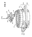
- FIG. 8 is a simplified perspective view a portion of the embodiment of FIG. 7 illustrating an invention as it may be applied to wastewater samplers;
- FIG. 9 is a simplified perspective view of a portion of the embodiment of FIG. 8 ;
- FIG. 10 is a simplified perspective view of another portion of the embodiment of FIG. 8 ;
- FIG. 11 is a simplified perspective view showing a stage in the development of an embodiment of FIG. 8 that comprises the embodiments of FIGS. 9 and 10 ;
- FIG. 12 is a simplified perspective view of the embodiment of FIG. 11 in a further stage of fabrication
- FIG. 13 is a flow diagram of a process of making a bottle rack
- FIG. 14 is a fragmentary perspective view of a portion of the embodiment of FIG. 7 ;
- FIG. 15 is a perspective view of another portion of the embodiment of FIG. 7 ;
- FIG. 16 is a simplified exploded perspective view of a portion of the embodiment of FIG. 14 ;
- FIG. 17 is an exploded perspective view of another portion of the embodiment of FIG. 14 ;
- FIG. 18 is a perspective view of an index disk that is component of the embodiment of FIG. 14 ;
- FIG. 19 is an exploded simplified perspective view of an embodiment of an invention as it may be used in a pump
- FIG. 20 is a simplified perspective view of the embodiment of FIG. 19 ;
- FIG. 21 is a simplified perspective, partly exploded away of a component of the embodiment of FIG. 19 ;
- FIG. 22 is a block diagram of a portion of a control system.
- FIG. 23 is a block diagram of a heating system in accordance with an embodiment of the invention.
- FIG. 1 there is shown a simplified perspective view of a sample collector 10 which is one type of apparatus that may include inventions described hereinafter and which has as its principal component parts a control system 12 , a peristaltic pump 14 , and an enclosed refrigerated sample bottle compartment 16 .
- the enclosed refrigeration system and sample bottle unit 16 is housed in an enclosure and has separately mounted above it the control system 12 to control the collection of samples in the refrigeration system and sample bottle unit 16 and a peristaltic pump 14 which, under the control of the control system 12 , may pump liquid samples such as waste water samples into bottles included within the refrigeration system and sample bottle unit 16 (the bottle rack and bottles are not shown in this view for clarity).
- the control system 12 includes a touch screen 26 for the control system 12 .
- the peristaltic pump 14 is mounted to the side of the control system 12 and is controlled thereby to draw samples and cause them to flow into bottles within a refrigerated compartment 28 .
- the peristaltic pump 14 includes pump inlet and outlet tubing 200 and 202 .
- the enclosed refrigeration system and sample bottle unit 16 includes a refrigerated sample bottle compartment 28 and a refrigeration system 46 .
- the refrigeration system 46 cools the refrigerated compartment 28 which is designed to include sample bottles and a distributor arm which fills the bottles with samples in accordance with the control system 12 .
- the peristaltic pump 14 under the control of the control system 12 determines when to draw a sample and the amount of sample to be deposited in the bottles.
- the control system 12 , refrigeration system and sample bottle unit 16 and peristaltic pump 14 cooperate together in the manner described in U.S. Pat. No. 5,915,932, the disclosure which is incorporated herein by reference.
- the refrigerated sample compartment 28 includes a distributor arm 18 , an opening for electrical connections a vent opening 25 through which air leaves the compartment 28 .
- a port and fan shown at 38 ( FIG. 2 ) blows cooled air into the refrigerated compartment 28 .
- the distributor arm 18 includes a distributor outlet 42 through which samples flow into sample bottles, a distributor hose 82 and side support members 40 A and 40 B for the distributor hose 82 .
- the peristaltic pump 14 is positioned with its paddle rollers having an axis of rotation that is horizontal so that it opens to the side. However, it may be positioned and hinged to open in other directions or orientations.
- FIG. 2 there is shown another simplified perspective view of a sample collector 10 from another side having the control system 12 , the peristaltic pump 14 , the enclosed refrigeration system and sample bottle unit 16 , the refrigeration section 46 , with the cooling assembly 34 shown removed.
- a cool air compartment 36 within the refrigeration section 46 includes a cool air space port 38 and a computer-compressor electrical connector 44 . Cool air flows through the port 38 into the refrigerated bottle compartment 28 ( FIG. 1 ).
- the cooling assembly 34 includes a back plate 50 , condenser coils 52 , a bottom support panel 54 , a compressor unit 56 and a fan 58 .
- the compressor unit 56 , the fan 58 , the back plate 50 and the condenser coils 52 are mounted to the plate.
- the evaporator coils (not shown in FIG. 2 ) are mounted to the back plate 50 so as to be supported on the bottom support panel 54 .
- the compressor 56 , the fan 58 , condenser 52 and evaporator coils are all moved as a single unit into the cooling compartment 36 or removed from the cooling compartment 36 .
- the sampling system 10 in one application is utilized to sample wastewater in a corrosive environment.
- a protective coating may be applied after these units are connected which permits a better seal than when the individual units are covered with a protective coating and then interconnected to each other since the connecting points are inadequately protected if they are coated first and then connected.
- a powder coating technique that causes the powder to flow into narrow spaces when the unit is already connected, unprotected connecting points are reduced and failure because of corrosion is reduced.
- the compressor is not connected prior to applying a protective coat to other units because the temperature at which powder coating is applied may damage the compressor.
- the other units are coated and then the compressor is connected leaving only the compressor connections to be separately coated.
- the condenser coils 52 , evaporator coils, the fan unit 58 , the restrictor, any other components and the connections between them may be coated after they are assembled and then special care taken for the few remaining connections to provide superior protection.
- Other coating materials and techniques such as zinc based paints applied as an aerosol or in which the connected units are dipped may permit the compressor to be connected before the combination is coated.
- FIG. 3 there is shown a perspective view of the cooling assembly 34 showing in greater detail the bottom support 54 having side members 62 and 66 , a bottom member 64 and an inner wall 60 .
- the bottom wall 64 supports the compressor 56 and a cooling fan (not shown in FIG. 3 ) with the back plate 50 having side walls 68 and 72 , a top wall 70 and the exposed condenser coils 52 .
- the condenser coils are positioned so that a fan 58 ( FIG. 2 ) flows air outwardly to remove heat.
- FIG. 4 there is shown a perspective view of the cooling assembly 34 from the opposite side as shown in FIG. 3 with the evaporating coils 74 shown mounted to the plate 72 to cool the cool air compartment 36 ( FIG. 2 ).
- a precision orifice 76 within the tubing provides an appropriate restriction to permit the building up of pressure in the condenser coils 52 and expansion in the evaporation coils 74 .
- Connections to the evaporator coils 74 and the compressor 56 ( FIG. 3 ), the condenser coils 52 are shown at 78 , 80 and 82 . These connections are made after powder coating or otherwise insulating the coils and restrictor and separately insulating the compressor.
- FIG. 5 there is shown a flow diagram 90 including the step 92 of assembling condenser coils, evaporation coils and a fan on a single unitary frame, the step 94 of powder coating the assembly of step 92 , the step 96 of mounting the compressor on the unitary frame and connecting the compressor to the condenser and evaporation coils, the step 98 of sealing the connections between the compressor and evaporation coils and the step 100 of mounting the unitary frame to the main refrigerated sampler.
- a protective coating may be efficiently applied and provide better protection then coating individual units and mounting them to the refrigerated sampler in a step by step process as the sampler is built up to include the necessary components.
- unitary frame also permits more economical servicing of the units since it can be easily disconnected and moved from the refrigerated sampler to perform service on it.
- unitary frame means the combination of support members and multiple components that include at least condenser and evaporator coils of a refrigeration unit that are supported together and may be removed as a unit from a refrigeration system and returned to the refrigeration unit to be connected as a single unit.
- FIG. 6 there is shown a flow diagram 102 including the step 104 of unfastening the unitary frame from the refrigerated sampler, the step 106 of pulling out the unitary frame, the step 108 of servicing the refrigerated sampler and principally the components mounted on the unitary frame and the step 110 of pushing the unitary frame back within the refrigerated sampler and fastening it in place.
- the refrigerated sampler may be more conveniently serviced by either removing the unitary frame to a location for servicing or merely removing it easily from the refrigerated sampler for servicing and even by replacing it with a different unitary frame temporarily while service is performed on the prior unitary frame. Access is more easily obtained to repair the parts and provide a protective coating where the coating may have been removed or damaged.
- the word “restrictor” shall include both capillary and orifice restrictors designed to provide a pressure differential between the evaporator coils and the condenser coils of a cooling unit.
- final closure shall mean an outside member that provides a suitable wall for the refrigerated sampler with the proper appearance and protection and yet be easily fastened to the refrigerated sampler. It permits easily fastening and unfastening without other obstructions so that it may be quickly unfastened to pull the unitary frame out and quickly fastened to provide a finished appearance to the refrigerated sampler.
- the words “special protective coat” shall mean a coat specially adapted to protect surfaces of components and connections between components in a corrosive environment.
- this coat should be obtained by the process known as powder coating after at least two of the components have been connected together so as to permit effective protection to the connections themselves in a corrosive environment.
- all of the components on the unitary frame except for the compressor are connected before the special coat is applied.
- FIG. 7 there is shown another perspective view of the refrigerated sampler 10 broken away to show the refrigerated sample compartment 28 with a plurality of sample bottles 114 mounted in a bottle rack 112 within the refrigeration compartment 28 .
- a distributor arm 18 is shown positioned over a bottle.
- a distributor arm positioning assembly 116 determines the position of the distributor arm 18 even though the distributor arm 18 may be freely moved by hand and thus have been moved out of position.
- the distributor arm positioning assembly 116 detects the location of the distributor arm 18 and moves the distributor arm 18 to the starting position by a stepping motor or any other drive means such as for example, an indication motor, a synchronous motor, a solenoid or linear actuator.
- the bottle rack 112 is mounted to a ledge within the refrigeration compartment 28 on which it rests so that it can be easily removed along with the sample bottles and a new rack with new sample bottles can be placed inside the refrigeration compartment 28 .
- a fan 280 blows cold air into the refrigeration compartment 28 .
- FIG. 8 there is shown a simplified perspective view of the distributing arm positioning assembly 116 , the distributor arm 18 , and the bottle rack 112 .
- the bottle rack 112 includes two injection molded sections 112 A and 112 B molded from a single cavity and positioned with their respective bases 126 A and 126 B in contact with each other.
- Each of the bases 126 A and 126 B has a cylindrical supporting and positioning wall 128 A ( FIG. 9) and 128B ( FIG. 10 ) extending from it.
- Each of these walls has a surface which contacts a corresponding one of the sample bottles 114 to provide a contact point against the bottle.
- the two units with the bottoms of their bases 126 A and 126 B in contact with each other provide two points of contacts against the surfaces of each bottle so as to firmly position them on one side.
- a central cylindrical member positions them on their inner surface (not shown in FIG. 8 ).
- the distributor arm 18 is located so as to have a central axis of rotation at the center of the circle of sample bottles within the bottle rack 112 . Its outlet is thus positioned in sequence over the bottles by a stepping motor.
- the distributor arm positioning assembly 116 includes a stepping motor 124 , a distributor assembly 122 , an index position sensor 120 , and an index disk 118 ( FIGS. 14 and 18 ).
- the index disk 118 has encoded on its periphery a code for each position. It rotates together with the distributor arm 18 so that the sensor 120 detects the position of the index disk 118 and thus the corresponding position of the distributor arm 18 .
- the difference between the sensed position and the position that the distributor arm 18 is determined by a microcontroller which controls the stepping motor to move the distributor arm 18 to the proper position.
- FIG. 9 there is shown a simplified perspective view of a bottle rack half 112 A having its base 126 A, the cylindrical supporting and positioning wall 128 A, handles 138 A, 240 A, 242 A and 144 A and bottle positioning members 130 A, 132 A, 134 A and 136 A.
- the positioning devices such as 134 A have a central arc for receiving the surface of one sample bottle and two arced side members each of which contacts another sample bottle.
- the three sample bottles positioned by each of the positioning members controls the position of all of the sample bottles between two positioning members.
- the location of the bottles may be calibrated to correspond to the code on the index disk 118 .
- the code on the index disk for the first bottle is set to correspond to the numeral one on the base 126 A as shown at 242 with the locations of the remainder of the bottles being indicated on the top surface of the base 126 A.
- FIG. 10 there is shown a perspective view of the second rack half 112 B of the bottle rack 112 having positioning members 130 B, 132 B, 134 B and 136 B ( 134 B and 136 B not being visible in FIG. 10 ). These are shaped in the same manner as the corresponding bottle positioning members in the first rack half 112 A ( FIG. 9 ). Similarly, since the base 126 B is molded in the same cavity as the base 126 A ( FIG. 9 ) and the cylindrical supporting and positioning wall 128 B is formed in the same cavity as 128 A, the two halves are identical as they are molded. However, as shown in FIG.
- both halves are molded with eight ribs extending radially from a connecting point to the bottle cylindrical supporting and positioning wall 154 A- 154 H.
- the ribs are trimmed off before the bases and positioned together.
- Spring members 152 are shown in position to snap into openings in the refrigerated compartment 28 to latch the rack in place.
- Each of the two bases has positioning members 130 B to 136 B ( FIG. 11 ) which are located together for exact positioning.
- the bottle rack may be economically molded using a single cavity injection mold and provide stable positioning of the bottles.
- the distance between the positioning devices on the base 112 A with the corresponding positioning member on the base 112 B is a stability design distance.
- the words “stability design distance” or similar words means the distance between two positioning surfaces on a stabilizing member that is sufficient to hold an item without wobbling about at least one point.
- a single stabilizing member may include multiple stability design distances one for each possible pivot point. Multiple stabilizing members may be used to stabilize one item and a single stabilizing member may stabilize more than one item.
- a positioning surface is a surface that is in contact with the surface of the item to be stabilized to hold it in position. In the preferred embodiment, the surface is the outer lateral surface of a sample bottle with the positioning members holding the sample bottle in position.
- FIG. 11 there is shown a bottle rack 112 in the process of assembly with the two rack halves 112 A and 112 B being positioned against each other to be fastened in place with the screws 158 A- 158 H that are threaded into corresponding holes.
- the ribs 154 A- 154 H are left at the bottom of the rack so that the bottles have their bottom against the ribs and their open tops extending upwardly.
- the positioning members 130 A- 136 A not shown in FIG. 1
- 130 B- 136 B With each of the bottles being supported by two of the positioning members 130 A- 136 A (not shown in FIG. 1 ) and 130 B- 136 B.
- the two positioning members such as for example 130 A and 130 B contact a bottle in two locations which are stability design distance apart.
- FIG. 12 there is shown a rack with the rack halves 112 A and 112 B positioned together to form a rack with a bottom surface 262 .
- the bottles rest on the bottom surface 262 mounted underneath the ribs 154 A- 154 G ( FIG. 11 ).
- the center of the bottom surface 262 includes a circle of air flow control openings 142 .
- the two aligned positioning members such as for example 134 A and 134 B (not shown in FIG. 12 ) position a bottle against side to side wobbling such as for example wobbling can be tangential to the cylinder 128 A and 128 B radial to the cylinder formed by the walls 128 A and 128 B.
- the bottles touch each other between the positioning members 130 A, 130 B- 136 A, 136 B (not shown in FIG. 12 ), they are prevented from movement between the position members by the adjacent bottles as long as the adjacent bottles have relatively straight sides.
- the positioning members align the bottles straight up and down in the tangential direction and prevent them from wobbling and the cylindrical walls prevent them from tilting in a radial direction or wobbling in the radial direction or moving out of position.
- FIG. 13 there is shown a flow diagram 164 of a step in manufacturing a bottle rack comprising the step 166 of preparing a single cavity mold for injection molding one rack half with at least one positioning surface for each bottle to be positioned, which positioning surface is one half of a stability design distance from one end of a half rack, the step 168 of injection molding two half racks for each rack desired, and the step 170 of inverting one half rack and fastening it to another half rack with one side of each half rack in contact so that at least one stabilizing member is formed with the one end being centered between two positioning surfaces.
- a single cavity injection mold may be used to manufacture all of the principal parts of the bottle rack.
- FIG. 14 there is shown a fragmentary view of a portion of the distributor arm positioning assembly 116 having a distributor assembly 122 , an index disk 118 , a sensor 120 and a portion of the distributor arm 18 .
- the index disk 118 is fastened by screws to rotate with the distributor arm 18 and is aligned so that a code on its surface indicating the position of the distributor arm passes under the sensor 120 .
- the code on the disk 118 consists of spaced-apart openings in the disk of different widths and combinations although any code could be used including magnetic codes or translucent portions or the like. In the case of a magnetic code, a magnetic pick up would be utilized. In the preferred embodiment the openings are made in a metal disk economically.
- the senor 120 includes a light source, which in the preferred embodiment is an LED, and a photocell, embedded in the sensor so that the index disk 118 passes between the sensor 120 with its code being directly between the photoelectric pick up and the LED. In this manner, signals are supplied from the sensor 120 and signals from the sensor 120 are supplied to a control system 252 ( FIG. 22 ) indicating the exact position of the distributor arm 18 .
- a light source which in the preferred embodiment is an LED
- a photocell embedded in the sensor so that the index disk 118 passes between the sensor 120 with its code being directly between the photoelectric pick up and the LED.
- FIG. 15 there is shown a simplified, partly broken away perspective view of the distributor arm 18 having a stepping motor 124 connected through a conductor 182 to a source of power, a conductor 180 connected to the sensor 120 ( FIG. 14 ) and to a control system 252 ( FIG. 22 ) to indicate the position of the index disk 118 ( FIG. 14 ) and distributor arm 18 and a drive shaft 172 driven by the distributor in synchronism with the index disk 118 ( FIG. 14 ).
- the distributor arm 18 includes a hose 82 having an opening 42 at one end and supporting members 40 A and 40 B to support it as it moves in a circle about the drive shaft 172 with its outlet 42 being offset from the longitudinal axis of the shaft 172 a sufficient distance so that with the shaft 172 being positioned at the center of the ring of sample bottles 114 ( FIG. 8 ), the opening will pass over the openings in the bottles.
- a nut 178 holds the distributor arm 18 to the shaft 172 .
- FIG. 16 there is shown an exploded simplified perspective view of the distributor arm positioning assembly having the stepper motor 124 , a shaft plate 188 , a drive belt 184 , a distributor gear 186 and the distributor base 174 .
- the stepping motor drive belt 184 engages the gear 186 in one portion and the stepping motor output shaft which passes through a center bushing 234 of the shaft plate 188 to drive the gear 186 below the shaft plate 188 .
- the stepping motor 124 steps from position to position it moves the drive belt 184 in synchronism which in turn turns the gear 186 to turn the distributor arm 18 and the index disk 118 ( FIG. 14 ).
- Power is applied to the motor 124 through the conductor 182 and signals are received from the sensor 120 ( FIG. 14 ) through the conductor 180 .
- FIG. 17 there is shown a exploded view of a portion of the distributor arm assembly 116 showing the index disk 118 spaced from the distributor gear 186 by a spacer 190 and positioned with respect to the distributor output shaft 172 , the distributor gear 186 , and the index disk 118 by screws 246 A- 246 D which pass through or into each of them to maintain them in synchronism.
- FIG. 18 there is shown a perspective view of the index disk 118 having openings to receive the screws 246 A- 246 -D ( FIG. 17 ) and a code placed on the periphery formed of opaque portions one of which is labeled 192 and openings of different sizes shown at 194 , 196 and 198 .
- These openings provide a unique code which indicates the exact location of the disk and thus the location of the outlet of the distributor arm with respect to the sample bottles.
- the unique code is based on the number of steps of a stepping motor as described above.
- the index disk includes a sequential series of codes, each indicating a position on the disk. While in the preferred embodiment, the codes indicate a unique position on a disk, they can indicate a unique position on any object which moves with respect to a sensor that senses the codes.
- Each unique code at a unique position is identified by a code identification character and a code character or other unique criteria such as for example, a pattern of indicia that does not repeat. The pattern may by comprised completely of code characters or may be separate from the code characters. It can be spatial or numerical and consist of any indicia including light and dark areas.
- Each code character is indicated by at least one code identification character to separate it from other code characters. In the preferred embodiment, two code identification characters are used, one on each side of the code character.
- Narrow openings are code identification characters that indicate the presence of code characters identifying the location.
- the narrow slots such as 196 indicate the presence of a code between it and the next narrow slot.
- wider portions such as 194 and 198 that constitute code characters.
- a code may include a plurality of code characters.
- the narrow portions have a width of seven to thirteen distances of a stepping motor step. The number of steps it take to cross the distance of the wider openings represents a code character. In the preferred embodiment, this is considered a numerical value. Where there are multiple adjacent wide spaces not separated with a narrow space, each of the wide spaces indicates a different code character which together form a code.
- the stepping motor when the distributor arm is not being moved by the stepping motor, the stepping motor is de-energized and the arm can rotate freely. However, once a command is given to move a distributor over a bottle, the stepping motor moves the distributor arm in a direction as commanded by the microcontroller.
- the microcontroller controls each step by issuing a signal for that step. It remembers the direction that the distributor arm was last moving and moves the distributor arm in that same direction as a start. However, as soon as the distributor arm recognizes a code portion from a narrow opening, it determines if it is moving in the desired direction to reach the bottle in a short time. If not, the microcontroller has the stepping motor change directions. The one or more code characters are recognized in the microcontroller as being the same specific location whether they read in one direction or in the opposite direction.
- a stop is provided at 290 which engages the distributor at 292 ( FIG. 15 ) in the event of a malfunction in which the code is misread and the microcontroller attempts to move too far in one direction.
- the microcontroller recognizes that the stepping motor has attempted to move too large a distance and does not order a sampling operation. Because this system recognizes unique locations, in many instances, the microcontroller continues operating in accordance with the procedures as described in the aforementioned patent.
- FIG. 19 there is shown an exploded perspective view of a peristaltic pump 14 having a peristaltic pump cover 204 , a metal pump band 206 and a pump base 208 .
- the pump base 208 has mounted to it a roller paddle 218 driven by a motor 230 with two rollers 220 A and 220 B mounted on the ends of the paddle to roll along a raceway 232 .
- Two positioning posts 224 A and 224 B hold a peristaltic pump tube 200 (not shown in FIG. 19 ) in position in the raceway 232 while the roller paddle 218 rolls against it driven by the motor 230 and an output shaft 222 to pump liquid through the peristaltic pump tube.
- Two peristaltic pump grooves 236 and 238 hold the peristaltic pump tube in a loop with a portion of it along the raceway 232 with one end of it extending along the contoured tube guide 238 and the other end along the contoured tube guide 236 .
- the contoured tube guides 236 and 238 are spaced from each other and the contoured tube guide 236 starts at an elevation lower than the raceway 232 and increases in height up to the raceway 232 while the contoured tube guide 238 is at an elevation higher than the raceway 232 and gradually lowers to an elevation at the raceway 232 .
- contoured tube guides 236 and 238 are shaped so that they apply the same bias to the peristaltic pump tube to maintain it in the raceway against the movement of the rollers 220 A and 220 B to avoid it from being moved from one side to another and being pinched.
- contoured tube guide means a tube guide leading to or from a raceway with a shape designed to reduce the tendency of the tube to move from the center of the raceway during a pumping operation.
- the contoured tube guide on one side of the raceway starts with a bottom edge below the top edge of the raceway and other starts with its bottom edge above the top edge of the raceway. Both of them connect with the raceway with their bottom edge equal to the top edge of the raceway.
- the curvature leading to these points is shaped, partly by trial and error, to provide a bias to the tube that reduces its motion from side to side to a minimum and thus avoids excess cutting and wear of the tube which otherwise would occur as the rollers force it against edges or the like of the raceway.
- the edges of the raceway are curved to reduce the tendency to cut the peristaltic tube.
- the raceway 232 has rounded edges to further avoid the wear on the peristaltic pump tube as the rollers exert a force in the direction of the flow of the liquid.
- the curves of the contoured path place a bend in the peristaltic pump tube in opposite directions with one rising and the other lowering in a symmetrical manner and slanting slightly toward the center of the raceway. With this contour, bias is placed on the peristaltic pump tube to resist its moving from one side to the other and thus the peristaltic pump tube avoids wear and lasts longer.
- the metal pump band 206 receives a hinge pin 210 on one end permitting it to open approximately 180 degrees so as to provide access to the peristaltic pump tube when opened but to protect it and hold it in place when closed.
- a hook 214 on one end fits within a cylindrical rolled radius 226 , which has a radium of curvature similar to the radium of curvature of the hook 214 so as to permit rolling motion between the two. This rolling motion reduces the flexing of the band. engages a keeper 226 to hold it in place when it is not opened.
- a toggle latch pulls the hook 214 to stretch and hold the band.
- a guide 282 prevents the hook 214 from being positioned too high and over the cylindrical rolled radius.
- the peristaltic pump cover 204 includes a hinged portion, a thumb screw 248 and an axle seat 250 .
- the axle seat 250 is aligned with the output shaft 222 and when the cover 204 is in place provides a seat to stabilize the output shaft 222 for the roller paddle 218 .
- the thumb screw 248 holds the cover 204 at one point to the base 216 and screws 212 A- 212 D hold the cover 204 to the base 216 at other locations.
- FIG. 20 there is shown another perspective view of a base 208 showing two ends of the peristaltic pump 200 and 202 within the contoured tube guides 236 and 238 but broken away so that it is not shown entering the raceway 232 .
- On one end of the base there is mounted by screws 234 A and 234 B a keeper and keeper guide 228 positioned so that the hook 214 ( FIG. 19 ) on the end of the metal band 206 ( FIG. 19 ) engages the keeper is held within the cylindrical rolled radius.
- the guide 282 prevents the hook from being positioned above the cylindrical rolled radium 226 rather than within it.
- the sides of the pump cover must provide at lest 180 degrees when operating. However, for easy installation or replacement of a tube when the band is opened, access shall be provided for at least 90 degrees and preferably between 120 degrees and 180 degrees in the preferred embodiment.
- FIG. 21 there is shown a perspective view of the band 206 showing the hinge 212 which engages the hinge pin 210 ( FIG. 19 ) to prevent opening and closing of the band 206 .
- FIG. 22 there is shown a block diagram of a control system 252 having a source of stepping motor pulses 266 , an index position sensor 120 , a gate 268 , a microcontroller 254 , the stepping motor 124 and the distributor arm 18 as its principle parts.
- the stepping motor 124 is connected to the distributor arm 18 to drive the distributor arm from position to position.
- An input device 256 is connected to the microcontroller 254 for altering of a program and applying commands.
- the gate 268 is connected to the index position sensor 120 through a conductor 180 so that, when the openings in the index disk are being sensed by the index position sensor 120 , the gate 268 is opened.
- the source of stepping motor pulses 266 is connected to the gate 268 through a conductor 270 so that stepping motor pulses are applied to the microcontroller 254 resulting in the microcontroller being able to access a database to interpret the pulses as a code indicating the exact position of the index disk and distributor.
- the microcontroller 254 may calculate the distance between the distributor arm and the direction it is to rotate and directly rotate the distributor arm over the mouth of a bottle for insertion of a sample or withdrawing of a sample as described in the aforementioned U.S. patent.
- the microcontroller 254 may activate the stepping motor 124 to return the distributor to its starting position and to begin counting to a specific bottle to be filled.
- the microcontroller determines if the pulses passing through the gate are in the range of the narrower slots such as 196 ( FIG. 18 ) or wide slots such as 194 ( FIG. 18 ). If the microcontroller recognizes a narrow slot, which is a code identification character, recognizes the next group of signals as representing a code character. Generally, the number of pulses that are applied to the microcontroller while a narrow slot is moving through the sensor may be considered as a single unit.
- the code character corresponding to the wide slot may be considered a five. If there are a series of wide slots not separated by a narrow slot, a series of such code characters are generated. For example, if there are two wide slots in a row, one equal to five and the other equal to three, the microcontroller recognizes 5,3 or 3,5 as being one side or the other of a unique bottle general location corresponding to a general location on the disk and unique position on the distributor. The microcontroller than identifies a narrow slot and the distance from the narrow slot corresponding to a bottle opening and moves the bottle opening.
- the reference point on the disk that positions the distributor at a location over a bottle is the trailing edge of the code identification character slot so that the resting position is recognized at the end of the traversal of a slot through the sensor.
- other reference points may be used instead such as one stepping motor step beyond the trailing edge and the distributor arm may be arbitrarily positioned and does not have to be aligned with any slot but may be offset a distance in accordance with the calibration of the index disk with the location of the distributor arm.
- the microcontroller remembers the direction that the distributor arm was last moving and starts the stepping motor in that direction after motion has been terminated
- other obvious algorithms may be utilized such as determining the direction by the order of the code characters on the disk or by separate indicia on the disk which point in one direction. For example, a wider slot that is distinguishable in its width from either the code character slots or the narrower marker slots followed by another slot indicating counterclockwise or a similar arrangement indicating clockwise.
- more than one sensor could be used either in the same tracks or multiple tracks although the expense is increased with each sensor and each track.
- FIG. 23 there is shown a system 260 for warming a compressor to a point where it may start when the ambient temperature is low.
- the fluid in the refrigeration system may liquefy. If it liquefies sufficiently and collects within the compressor, it may prevent the compressor from starting.
- the system 260 heats the compressor without any additional external heaters or controls so as to do so at a minimum cost and nonetheless permit the compressor to be sufficiently warm for starting.
- the system 260 includes a refrigeration compartment temperature sensor 272 , a power source 262 , an ambient temperature sensor 274 , a compressor control circuit 276 , a motor-winding heating-current control circuit 278 and the compressor 56 .
- the power source 262 , refrigeration compartment temperature sensor 272 , compressor control circuit 276 and compressor 56 are generally part of a standard refrigeration system. In some systems, there is an ambient temperature sensor 274 as well. However, in the embodiment of FIG. 23 , the compressor control circuit 276 in addition to running the compressor motor when the refrigeration compartment temperature sensor 272 indicates that the temperature in the refrigeration compartment is above the preset temperature, is also connected to the motor-winding heating-current control circuit 278 to indicate the status of the compressor motor.
- the power source 262 transmits power over conductor 182 to the compressor control circuit 276 to drive the compressor 56 when the compressor control circuit 276 determines that temperature in the refrigeration compartment is too high.
- the power source 262 also supplies power to the motor-winding heating-current control circuit 278 but this power is of a nature that does not run the compressor 56 when applied to the compressor motor windings. It may be attenuated by an attenuator 270 so that the voltage is too low to start the compressor motor but other mechanisms may be utilized such as an opposing voltage or a frequency that does not operate the motor or may have any other characteristic, wave shape or form that supplies current to the windings to generate heat but does not operate the motor.
- the ambient temperature sensor 274 applies a signal to the motor-winding heating-current control circuit 278 and when the ambient temperature is sufficiently low to indicate a possibility that the compressor motor will not operate and the motor-winding heating-current control circuit is receiving a signal from the compressor control circuit 276 indicating that the compressor motor is not on, the motor-winding heating-current control circuit 278 applies a signal to the compressor 56 to warm the compressor 56 .
- the heating current is applied to the field winding of a stepping motor, it could be applied to any resistive conductor in any drive mechanism.
- the sample collector and the components that are used in the sample collector and other apparatus have several advantages, such as: (1) they provide an economical method of forming a bottle rack; (2) they provide a superior protective coat to equipment that may be used in a corrosive environment; (3) they provide an inexpensive position sensor that indicates a unique position with simple equipment; (4) they provide an improved peristaltic pump in which a metal band utilized to close the pump is more easily positioned; (5) they provides a superior peristaltic pump tube guideway that reduces the wear on the peristaltic tube; and (6) they provide a particularly inexpensive system for maintaining a compressor sufficiently warm in a cold environment for ease of starting.
Abstract
Description
Claims (7)
Priority Applications (2)
| Application Number | Priority Date | Filing Date | Title |
|---|---|---|---|
| US11/980,261 US8056353B2 (en) | 2006-05-09 | 2007-10-30 | Sample collector and components thereof |
| US13/294,915 US8393166B2 (en) | 2006-05-09 | 2011-11-11 | Sample collector and components thereof |
Applications Claiming Priority (2)
| Application Number | Priority Date | Filing Date | Title |
|---|---|---|---|
| US11/430,606 US8883090B2 (en) | 2006-05-09 | 2006-05-09 | Sample collector and components thereof |
| US11/980,261 US8056353B2 (en) | 2006-05-09 | 2007-10-30 | Sample collector and components thereof |
Related Parent Applications (1)
| Application Number | Title | Priority Date | Filing Date |
|---|---|---|---|
| US11/430,606 Division US8883090B2 (en) | 2006-05-09 | 2006-05-09 | Sample collector and components thereof |
Related Child Applications (1)
| Application Number | Title | Priority Date | Filing Date |
|---|---|---|---|
| US13/294,915 Division US8393166B2 (en) | 2006-05-09 | 2011-11-11 | Sample collector and components thereof |
Publications (2)
| Publication Number | Publication Date |
|---|---|
| US20080053143A1 US20080053143A1 (en) | 2008-03-06 |
| US8056353B2 true US8056353B2 (en) | 2011-11-15 |
Family
ID=38683838
Family Applications (5)
| Application Number | Title | Priority Date | Filing Date |
|---|---|---|---|
| US11/430,606 Expired - Fee Related US8883090B2 (en) | 2006-05-09 | 2006-05-09 | Sample collector and components thereof |
| US11/980,030 Abandoned US20080120990A1 (en) | 2006-05-09 | 2007-10-30 | Sample collector and components thereof |
| US11/980,261 Expired - Fee Related US8056353B2 (en) | 2006-05-09 | 2007-10-30 | Sample collector and components thereof |
| US12/465,195 Abandoned US20090217696A1 (en) | 2006-05-09 | 2009-05-13 | Sample collector and components thereof |
| US13/294,915 Active US8393166B2 (en) | 2006-05-09 | 2011-11-11 | Sample collector and components thereof |
Family Applications Before (2)
| Application Number | Title | Priority Date | Filing Date |
|---|---|---|---|
| US11/430,606 Expired - Fee Related US8883090B2 (en) | 2006-05-09 | 2006-05-09 | Sample collector and components thereof |
| US11/980,030 Abandoned US20080120990A1 (en) | 2006-05-09 | 2007-10-30 | Sample collector and components thereof |
Family Applications After (2)
| Application Number | Title | Priority Date | Filing Date |
|---|---|---|---|
| US12/465,195 Abandoned US20090217696A1 (en) | 2006-05-09 | 2009-05-13 | Sample collector and components thereof |
| US13/294,915 Active US8393166B2 (en) | 2006-05-09 | 2011-11-11 | Sample collector and components thereof |
Country Status (5)
| Country | Link |
|---|---|
| US (5) | US8883090B2 (en) |
| EP (1) | EP2016354A4 (en) |
| JP (1) | JP2009536716A (en) |
| CN (1) | CN101466987A (en) |
| WO (1) | WO2007133565A2 (en) |
Families Citing this family (11)
| Publication number | Priority date | Publication date | Assignee | Title |
|---|---|---|---|---|
| CN102200789A (en) * | 2010-03-22 | 2011-09-28 | 鸿富锦精密工业(深圳)有限公司 | Temperature monitoring device |
| CN103499473B (en) * | 2013-10-23 | 2015-12-02 | 中国科学院合肥物质科学研究院 | A kind of fully automatic liquid impacting type biological sampling robot system |
| FR3046836B1 (en) * | 2016-01-18 | 2019-05-10 | Cryopal | RESERVOIR FOR STORING PRODUCTS AT CRYOGENIC TEMPERATURES |
| CN106771290B (en) * | 2017-02-17 | 2018-03-06 | 辽宁英创科技发展有限公司 | A kind of automatic check analysis system of robot and application method |
| DE102018113513A1 (en) * | 2018-06-06 | 2019-12-12 | Binder Gmbh | Holding device for a water collecting tray for a simulation cabinet |
| JP2019214027A (en) * | 2018-06-14 | 2019-12-19 | 古野電気株式会社 | Support adjustment member, vessel accommodation rack and analyzer |
| KR102106011B1 (en) * | 2018-09-13 | 2020-04-29 | 엘지전자 주식회사 | Method for controlling linear compressor and refrigerator |
| CN112730277A (en) * | 2019-10-28 | 2021-04-30 | 佳能医疗系统株式会社 | Automatic analyzer and reagent library thereof |
| CN111870982A (en) * | 2020-07-15 | 2020-11-03 | 江西渠成氟化学有限公司 | Purification device for fluoride production and processing and use method |
| CN114870930B (en) * | 2022-04-14 | 2023-07-11 | 重庆大学附属涪陵医院 | Physical examination blood sample storage device that draws blood |
| CN117517124B (en) * | 2023-11-16 | 2024-03-26 | 四川省产品质量监督检验检测院 | A device for white spirit solid detects in batches |
Citations (20)
| Publication number | Priority date | Publication date | Assignee | Title |
|---|---|---|---|---|
| US2294720A (en) | 1939-07-25 | 1942-09-01 | Ibm | Apparatus for verifying statistical data |
| US2435807A (en) | 1944-01-29 | 1948-02-10 | Udell Nathan | Device for washing bottles |
| US2729072A (en) | 1951-01-08 | 1956-01-03 | Gen Motors Corp | Refrigerating apparatus having reheating means |
| US3006077A (en) | 1958-03-03 | 1961-10-31 | Production Control Units Inc | Apparatus for dehydration of refrigeration hermetic compressors |
| US4534706A (en) * | 1983-02-22 | 1985-08-13 | Armco Inc. | Self-compensating oscillatory pump control |
| US4964533A (en) | 1985-03-18 | 1990-10-23 | Isco, Inc. | Pumping system |
| US5025936A (en) * | 1989-10-30 | 1991-06-25 | David Lamoureaux | Rack for storing and displaying bottles |
| US5149563A (en) * | 1991-06-06 | 1992-09-22 | The Boeing Company | Method for electrostatically coating plaster mandrels |
| US5299141A (en) * | 1989-12-22 | 1994-03-29 | American Sigma, Inc. | Automatic fluid monitoring and sampling apparatus and method |
| US5344672A (en) * | 1992-05-14 | 1994-09-06 | Sanderson Plumbing Products, Inc. | Process for producing powder coated plastic product |
| US5364657A (en) * | 1990-04-06 | 1994-11-15 | The University Of Akron | Method of depositing and fusing polymer particles onto moistened continuous filaments |
| US5463874A (en) | 1993-10-04 | 1995-11-07 | Tecumseh Products Company | Inductively activated control and protection circuit for refrigeration systems |
| US5506791A (en) * | 1989-12-22 | 1996-04-09 | American Sigma, Inc. | Multi-function flow monitoring apparatus with multiple flow sensor capability |
| US5587926A (en) | 1989-12-22 | 1996-12-24 | American Sigma, Inc. | Refrigerated fluid sampling apparatus and method with variable volume sampling system |
| US5753302A (en) * | 1996-04-09 | 1998-05-19 | David Sarnoff Research Center, Inc. | Acoustic dispenser |
| US5824373A (en) * | 1994-04-20 | 1998-10-20 | Herbert's Powder Coatings, Inc. | Radiation curing of powder coatings on wood |
| US5947305A (en) | 1998-01-16 | 1999-09-07 | Lin; Chen Yuan | Modular rack for wine bottles |
| US6214421B1 (en) | 1997-04-09 | 2001-04-10 | Dennis Pidzarko | Method of powder coating |
| US6354345B1 (en) | 1990-02-02 | 2002-03-12 | Isco, Inc. | Pumping system |
| US20060042298A1 (en) * | 2003-04-29 | 2006-03-02 | Imi Cornelius Inc. | Combined ice and beverage dispenser and icemaker |
Family Cites Families (25)
| Publication number | Priority date | Publication date | Assignee | Title |
|---|---|---|---|---|
| US3221719A (en) * | 1963-01-11 | 1965-12-07 | Gerald M Hilby | Automotive assembly |
| US3570462A (en) * | 1967-05-17 | 1971-03-16 | Auto Union Gmbh | Suction pipe heating by exhaust gas |
| US3767364A (en) * | 1971-07-30 | 1973-10-23 | Sherwood Medical Ind Inc | Reagent pipette system |
| US3927701A (en) * | 1972-04-04 | 1975-12-23 | Instrumentation Specialties Co | Sample collector |
| GB1497672A (en) * | 1974-01-22 | 1978-01-12 | Newton & Taylor Ltd | Bottle racks particularly racks for wine bottles |
| US4054932A (en) * | 1976-02-02 | 1977-10-18 | Square D Company | Over-current protective apparatus for a power circuit |
| US4415011A (en) * | 1981-11-02 | 1983-11-15 | Isco, Inc. | Sample collector |
| DE3809569A1 (en) * | 1988-03-22 | 1989-10-05 | Frankl & Kirchner | POSITION SENSOR |
| US5212380A (en) * | 1989-10-26 | 1993-05-18 | Optec D.D. Meico Laboratory Co., Ltd. | Automotive engine control system with rotary encoder indexing |
| US5168763A (en) * | 1990-12-17 | 1992-12-08 | Marathon Oil Company | Method and apparatus for collecting coreflood fluids |
| US5184462A (en) * | 1991-03-19 | 1993-02-09 | Oskar Schatz | Method and an apparatus for the treatment of exhaust gas from an IC engine |
| US5645114A (en) * | 1992-05-11 | 1997-07-08 | Cytologix Corporation | Dispensing assembly with interchangeable cartridge pumps |
| JP3099634B2 (en) | 1994-04-25 | 2000-10-16 | 株式会社日立製作所 | refrigerator |
| JP3216438B2 (en) | 1994-09-16 | 2001-10-09 | 株式会社日立製作所 | Heat exchanger for heat dissipation of refrigerator |
| US6138469A (en) | 1995-09-20 | 2000-10-31 | Sun Microsystems, Inc. | Refrigeration system for electronic components having environmental isolation |
| US5881567A (en) | 1997-09-29 | 1999-03-16 | Whirlpool Corporation | Refrigerator condenser air flow |
| DE19960668C1 (en) * | 1999-12-15 | 2001-08-16 | W O M Gmbh Physikalisch Medizi | Hose cassette for a peristaltic pump |
| DE10252158B4 (en) * | 2001-12-03 | 2004-11-04 | Endress + Hauser Wetzer Gmbh + Co Kg | Storage container for samplers |
| US6619034B1 (en) * | 2002-03-27 | 2003-09-16 | Ford Motor Company | Method and apparatus for reducing vehicular emissions by selectively heating a catalytic converter |
| EP1410935B1 (en) * | 2002-10-18 | 2005-08-10 | Ford Global Technologies, LLC | Method for reducing exhaust emission of an engine system |
| JP3901077B2 (en) * | 2002-11-14 | 2007-04-04 | ブラザー工業株式会社 | Image forming apparatus |
| US7886579B2 (en) * | 2003-10-09 | 2011-02-15 | Endress + Hauser Wetzer Gmbh + Co. Kg | Portable sampler |
| US7421881B2 (en) * | 2003-10-27 | 2008-09-09 | Baker Hughes Incorporated | Method and system for degassing a fluid |
| US20050172654A1 (en) | 2003-11-20 | 2005-08-11 | Hussmann Corporation | Modular refrigeration unit |
| US7232038B2 (en) * | 2004-04-27 | 2007-06-19 | Whitney Steven G | Disposable test tube rack |
-
2006
- 2006-05-09 US US11/430,606 patent/US8883090B2/en not_active Expired - Fee Related
-
2007
- 2007-05-08 CN CN 200780021366 patent/CN101466987A/en active Pending
- 2007-05-08 EP EP07756236A patent/EP2016354A4/en not_active Withdrawn
- 2007-05-08 WO PCT/US2007/011149 patent/WO2007133565A2/en active Application Filing
- 2007-05-08 JP JP2009509826A patent/JP2009536716A/en active Pending
- 2007-10-30 US US11/980,030 patent/US20080120990A1/en not_active Abandoned
- 2007-10-30 US US11/980,261 patent/US8056353B2/en not_active Expired - Fee Related
-
2009
- 2009-05-13 US US12/465,195 patent/US20090217696A1/en not_active Abandoned
-
2011
- 2011-11-11 US US13/294,915 patent/US8393166B2/en active Active
Patent Citations (20)
| Publication number | Priority date | Publication date | Assignee | Title |
|---|---|---|---|---|
| US2294720A (en) | 1939-07-25 | 1942-09-01 | Ibm | Apparatus for verifying statistical data |
| US2435807A (en) | 1944-01-29 | 1948-02-10 | Udell Nathan | Device for washing bottles |
| US2729072A (en) | 1951-01-08 | 1956-01-03 | Gen Motors Corp | Refrigerating apparatus having reheating means |
| US3006077A (en) | 1958-03-03 | 1961-10-31 | Production Control Units Inc | Apparatus for dehydration of refrigeration hermetic compressors |
| US4534706A (en) * | 1983-02-22 | 1985-08-13 | Armco Inc. | Self-compensating oscillatory pump control |
| US4964533A (en) | 1985-03-18 | 1990-10-23 | Isco, Inc. | Pumping system |
| US5025936A (en) * | 1989-10-30 | 1991-06-25 | David Lamoureaux | Rack for storing and displaying bottles |
| US5506791A (en) * | 1989-12-22 | 1996-04-09 | American Sigma, Inc. | Multi-function flow monitoring apparatus with multiple flow sensor capability |
| US5299141A (en) * | 1989-12-22 | 1994-03-29 | American Sigma, Inc. | Automatic fluid monitoring and sampling apparatus and method |
| US5587926A (en) | 1989-12-22 | 1996-12-24 | American Sigma, Inc. | Refrigerated fluid sampling apparatus and method with variable volume sampling system |
| US6354345B1 (en) | 1990-02-02 | 2002-03-12 | Isco, Inc. | Pumping system |
| US5364657A (en) * | 1990-04-06 | 1994-11-15 | The University Of Akron | Method of depositing and fusing polymer particles onto moistened continuous filaments |
| US5149563A (en) * | 1991-06-06 | 1992-09-22 | The Boeing Company | Method for electrostatically coating plaster mandrels |
| US5344672A (en) * | 1992-05-14 | 1994-09-06 | Sanderson Plumbing Products, Inc. | Process for producing powder coated plastic product |
| US5463874A (en) | 1993-10-04 | 1995-11-07 | Tecumseh Products Company | Inductively activated control and protection circuit for refrigeration systems |
| US5824373A (en) * | 1994-04-20 | 1998-10-20 | Herbert's Powder Coatings, Inc. | Radiation curing of powder coatings on wood |
| US5753302A (en) * | 1996-04-09 | 1998-05-19 | David Sarnoff Research Center, Inc. | Acoustic dispenser |
| US6214421B1 (en) | 1997-04-09 | 2001-04-10 | Dennis Pidzarko | Method of powder coating |
| US5947305A (en) | 1998-01-16 | 1999-09-07 | Lin; Chen Yuan | Modular rack for wine bottles |
| US20060042298A1 (en) * | 2003-04-29 | 2006-03-02 | Imi Cornelius Inc. | Combined ice and beverage dispenser and icemaker |
Also Published As
| Publication number | Publication date |
|---|---|
| US8393166B2 (en) | 2013-03-12 |
| WO2007133565A2 (en) | 2007-11-22 |
| EP2016354A4 (en) | 2012-03-07 |
| US20080053143A1 (en) | 2008-03-06 |
| WO2007133565A3 (en) | 2008-06-12 |
| US20120285183A1 (en) | 2012-11-15 |
| WO2007133565A8 (en) | 2008-12-04 |
| US20090217696A1 (en) | 2009-09-03 |
| EP2016354A2 (en) | 2009-01-21 |
| JP2009536716A (en) | 2009-10-15 |
| US20070261430A1 (en) | 2007-11-15 |
| US20080120990A1 (en) | 2008-05-29 |
| CN101466987A (en) | 2009-06-24 |
| US8883090B2 (en) | 2014-11-11 |
Similar Documents
| Publication | Publication Date | Title |
|---|---|---|
| US8056353B2 (en) | Sample collector and components thereof | |
| US20200236817A1 (en) | Computer Server Heat Regulation Utilizing Integrated Precision Air Flow | |
| US10654699B2 (en) | Water dispenser | |
| CN107917246A (en) | The valve member for flowing and controlling with improved fluid | |
| US6382256B2 (en) | Three-way flow control valve | |
| US10408468B2 (en) | Supply manifold with rotatable slider | |
| CN106373270B (en) | Automatic vending machine | |
| US4192149A (en) | Post condenser loop case heater controlled by ambient humidity | |
| US6880359B2 (en) | Flow-through rotary damper providing compartment selectivity for a multi-compartment refrigerator | |
| JP2009536716A5 (en) | ||
| CN1913804A (en) | A hot and cold vending machine | |
| US11785894B2 (en) | Indoor gardening appliance including grow tower with modular grow modules | |
| US11825786B2 (en) | Indoor garden center with a drive assembly utilizing positional feedback | |
| JP2008505300A (en) | Method and apparatus for operating a cryogenic device in a gaseous environment | |
| US4819442A (en) | Refrigerator system, control device therefor and methods of making and operating the same | |
| US20230000024A1 (en) | System and method for detecting a tower positioning fault using a drive assembly in an indoor garden center | |
| EP3896355A1 (en) | Air conditioner and control method therefor | |
| CN106574735B (en) | Multi-vane throttle valve | |
| CN107861543A (en) | A kind of microtensile testing machine temperature control box | |
| US11359854B2 (en) | Air damper with stepper motor | |
| US5144815A (en) | Thermal valve for compressor | |
| JPS5928305Y2 (en) | Refrigeration equipment for low temperature warehouses | |
| CN116620696A (en) | Multi-open intelligent storage cabinet for port logistics assembly | |
| SU849162A1 (en) | Program control | |
| WO2004099689A1 (en) | Temperature control using ultraviolet measurement light |
Legal Events
| Date | Code | Title | Description |
|---|---|---|---|
| ZAAA | Notice of allowance and fees due |
Free format text: ORIGINAL CODE: NOA |
|
| ZAAB | Notice of allowance mailed |
Free format text: ORIGINAL CODE: MN/=. |
|
| STCF | Information on status: patent grant |
Free format text: PATENTED CASE |
|
| FEPP | Fee payment procedure |
Free format text: PAYER NUMBER DE-ASSIGNED (ORIGINAL EVENT CODE: RMPN); ENTITY STATUS OF PATENT OWNER: LARGE ENTITY Free format text: PAYOR NUMBER ASSIGNED (ORIGINAL EVENT CODE: ASPN); ENTITY STATUS OF PATENT OWNER: LARGE ENTITY |
|
| FEPP | Fee payment procedure |
Free format text: PAYOR NUMBER ASSIGNED (ORIGINAL EVENT CODE: ASPN); ENTITY STATUS OF PATENT OWNER: LARGE ENTITY |
|
| AS | Assignment |
Owner name: TELEDYNE INSTRUMENTS, INC., CALIFORNIA Free format text: MERGER;ASSIGNOR:TELEDYNE ISCO, INC.;REEL/FRAME:027611/0988 Effective date: 20111221 |
|
| AS | Assignment |
Owner name: TELEDYNE ISCO, INC., NEBRASKA Free format text: ASSIGNMENT OF ASSIGNORS INTEREST;ASSIGNORS:FIEDLER, ROBERT R.;NABITY, FREDERICK A.;WALTERS, HENRY L.;REEL/FRAME:028603/0556 Effective date: 20060629 |
|
| FPAY | Fee payment |
Year of fee payment: 4 |
|
| MAFP | Maintenance fee payment |
Free format text: PAYMENT OF MAINTENANCE FEE, 8TH YEAR, LARGE ENTITY (ORIGINAL EVENT CODE: M1552); ENTITY STATUS OF PATENT OWNER: LARGE ENTITY Year of fee payment: 8 |
|
| FEPP | Fee payment procedure |
Free format text: MAINTENANCE FEE REMINDER MAILED (ORIGINAL EVENT CODE: REM.); ENTITY STATUS OF PATENT OWNER: LARGE ENTITY |
|
| LAPS | Lapse for failure to pay maintenance fees |
Free format text: PATENT EXPIRED FOR FAILURE TO PAY MAINTENANCE FEES (ORIGINAL EVENT CODE: EXP.); ENTITY STATUS OF PATENT OWNER: LARGE ENTITY |
|
| STCH | Information on status: patent discontinuation |
Free format text: PATENT EXPIRED DUE TO NONPAYMENT OF MAINTENANCE FEES UNDER 37 CFR 1.362 |
|
| FP | Lapsed due to failure to pay maintenance fee |
Effective date: 20231115 |