US8061382B2 - Sanitary valve assembly - Google Patents
Sanitary valve assembly Download PDFInfo
- Publication number
- US8061382B2 US8061382B2 US12/323,107 US32310708A US8061382B2 US 8061382 B2 US8061382 B2 US 8061382B2 US 32310708 A US32310708 A US 32310708A US 8061382 B2 US8061382 B2 US 8061382B2
- Authority
- US
- United States
- Prior art keywords
- valve
- valve body
- pressure
- pressure release
- valve assembly
- Prior art date
- Legal status (The legal status is an assumption and is not a legal conclusion. Google has not performed a legal analysis and makes no representation as to the accuracy of the status listed.)
- Active, expires
Links
- 239000011800 void material Substances 0.000 claims description 25
- 238000007789 sealing Methods 0.000 claims description 14
- 238000004140 cleaning Methods 0.000 claims description 5
- 238000003780 insertion Methods 0.000 claims 3
- 230000037431 insertion Effects 0.000 claims 3
- 238000007689 inspection Methods 0.000 claims 3
- 238000000926 separation method Methods 0.000 claims 2
- 239000000758 substrate Substances 0.000 abstract description 10
- 239000007788 liquid Substances 0.000 abstract description 7
- 239000000356 contaminant Substances 0.000 abstract description 2
- 239000007789 gas Substances 0.000 description 9
- 230000000007 visual effect Effects 0.000 description 7
- 230000003247 decreasing effect Effects 0.000 description 6
- 230000000712 assembly Effects 0.000 description 5
- 238000000429 assembly Methods 0.000 description 5
- 235000013361 beverage Nutrition 0.000 description 3
- 229910000831 Steel Inorganic materials 0.000 description 2
- 230000006835 compression Effects 0.000 description 2
- 238000007906 compression Methods 0.000 description 2
- 239000012530 fluid Substances 0.000 description 2
- 239000000463 material Substances 0.000 description 2
- 230000007246 mechanism Effects 0.000 description 2
- 239000002184 metal Substances 0.000 description 2
- 239000004033 plastic Substances 0.000 description 2
- 239000004417 polycarbonate Substances 0.000 description 2
- 229920000515 polycarbonate Polymers 0.000 description 2
- 239000007787 solid Substances 0.000 description 2
- 239000010959 steel Substances 0.000 description 2
- -1 without limitation Substances 0.000 description 2
- 238000009825 accumulation Methods 0.000 description 1
- 238000010276 construction Methods 0.000 description 1
- 238000011109 contamination Methods 0.000 description 1
- 230000006378 damage Effects 0.000 description 1
- 230000001066 destructive effect Effects 0.000 description 1
- 238000004880 explosion Methods 0.000 description 1
- 230000001050 lubricating effect Effects 0.000 description 1
- 239000002245 particle Substances 0.000 description 1
- 230000001681 protective effect Effects 0.000 description 1
- 230000000284 resting effect Effects 0.000 description 1
- 239000010907 stover Substances 0.000 description 1
- 239000000126 substance Substances 0.000 description 1
Images


Classifications
-
- F—MECHANICAL ENGINEERING; LIGHTING; HEATING; WEAPONS; BLASTING
- F16—ENGINEERING ELEMENTS AND UNITS; GENERAL MEASURES FOR PRODUCING AND MAINTAINING EFFECTIVE FUNCTIONING OF MACHINES OR INSTALLATIONS; THERMAL INSULATION IN GENERAL
- F16K—VALVES; TAPS; COCKS; ACTUATING-FLOATS; DEVICES FOR VENTING OR AERATING
- F16K15/00—Check valves
- F16K15/02—Check valves with guided rigid valve members
- F16K15/025—Check valves with guided rigid valve members the valve being loaded by a spring
-
- Y—GENERAL TAGGING OF NEW TECHNOLOGICAL DEVELOPMENTS; GENERAL TAGGING OF CROSS-SECTIONAL TECHNOLOGIES SPANNING OVER SEVERAL SECTIONS OF THE IPC; TECHNICAL SUBJECTS COVERED BY FORMER USPC CROSS-REFERENCE ART COLLECTIONS [XRACs] AND DIGESTS
- Y10—TECHNICAL SUBJECTS COVERED BY FORMER USPC
- Y10T—TECHNICAL SUBJECTS COVERED BY FORMER US CLASSIFICATION
- Y10T137/00—Fluid handling
- Y10T137/598—With repair, tapping, assembly, or disassembly means
- Y10T137/599—Pressure regulating type valve
-
- Y—GENERAL TAGGING OF NEW TECHNOLOGICAL DEVELOPMENTS; GENERAL TAGGING OF CROSS-SECTIONAL TECHNOLOGIES SPANNING OVER SEVERAL SECTIONS OF THE IPC; TECHNICAL SUBJECTS COVERED BY FORMER USPC CROSS-REFERENCE ART COLLECTIONS [XRACs] AND DIGESTS
- Y10—TECHNICAL SUBJECTS COVERED BY FORMER USPC
- Y10T—TECHNICAL SUBJECTS COVERED BY FORMER US CLASSIFICATION
- Y10T137/00—Fluid handling
- Y10T137/7722—Line condition change responsive valves
- Y10T137/7738—Pop valves
-
- Y—GENERAL TAGGING OF NEW TECHNOLOGICAL DEVELOPMENTS; GENERAL TAGGING OF CROSS-SECTIONAL TECHNOLOGIES SPANNING OVER SEVERAL SECTIONS OF THE IPC; TECHNICAL SUBJECTS COVERED BY FORMER USPC CROSS-REFERENCE ART COLLECTIONS [XRACs] AND DIGESTS
- Y10—TECHNICAL SUBJECTS COVERED BY FORMER USPC
- Y10T—TECHNICAL SUBJECTS COVERED BY FORMER US CLASSIFICATION
- Y10T137/00—Fluid handling
- Y10T137/7722—Line condition change responsive valves
- Y10T137/7837—Direct response valves [i.e., check valve type]
- Y10T137/7904—Reciprocating valves
- Y10T137/7922—Spring biased
- Y10T137/7929—Spring coaxial with valve
- Y10T137/7932—Valve stem extends through fixed spring abutment
Definitions
- the present invention relates to valve assemblies, and more particularly to sanitary valve assemblies having adjustable pressure relief mechanisms, removable lids or tops that may be reset when an overpressure situation has occurred and removable parts to provide access to the interior of the valve without having to disengage the valve from the pressurized substrate.
- valve assemblies to relieve pressure is well known in the art.
- U.S. Pat. No. 1,124,203 to Bingley discloses a safety valve suitable for use in connection with the brake cylinder of an air brake apparatus that prevents excessive pressure in the brake cylinder such as might result in the locking of car wheels.
- U.S. Pat. No. 1,891,119 to Stover discloses a safety valve designed to relieve pressure in a vessel, such as the cylinder of a compressor when excessive pressure accumulates therein.
- U.S. Pat. No. 2,254,209 to Buttner discloses a pressure relief valve that prevents the accumulation of fluid under or behind a sealing member in a valve.
- U.S. Pat. No. 2,710,627 to Wagner, et al. discloses a pressure controlling cap structure which vents any excess pressure within a cooker vessel.
- U.S. Pat. No. 3,651,827 to Hammer, et al. discloses a pressure relief valve that is connected on one side to a high pressure of a fluid or hydraulic or lubricating system and on the other side to a low pressure side.
- U.S. Pat. No. 4,049,017 to Jones discloses a pressure relief valve having a sealing member which is capable of moving into and out of sealing engagement with a valve seat as the valve member slides in the passageway.
- U.S. Pat. No. 4,143,787 to Walker discloses an air vent pressure relief plug for use with pressure cookers.
- U.S. Pat. No. 4,889,151 to Oten discloses a pressure relief valve having a valve member that smacks and permanently deforms a deformable over pressure indicating element to give a permanent indication of an over pressure situation.
- U.S. Pat. No. 5,623,962 to Danzy, et al. discloses a pressure relief valve having an inlet port and an outlet.
- U.S. Pat. No. 6,668,853 to Dean discloses a pressure relief valve for use in highly corrosive environments having parts exposed to corrosive lading which are relatively easily field-replaceable.
- a pressure relief valve assembly that allows a user to adjust the pressure needed to activate the pressure relief feature of the valve. This feature is useful because a closed system such as a tank may be used to transport or store a variety of gases and liquids. Because different liquids and gases create varying pressure conditions in a closed system, it would be desirable to have a pressure relief valve assembly that is adjustable.
- a valve assembly may accumulate build-up or residue from gas or liquid that remain on its surface. To avoid such build-up or residue, it would be desirable and advantageous to have a valve assembly that allows easy access and cleaning of the interior chamber of a closed valve assembly. Further, it is desirable and advantageous to have a valve assembly that can be accessed, inspected and cleaned without having to remove valve assembly from the pressurized vessel or substrate, keeping the vessel or substrate in a pressurized state while examining the interior of the valve assembly.
- valve assembly with a visual cue that alerts a user that a certain pressure has been exceeded in the system.
- valve assembly allowed a user to reset the visual cue that indicated the overpressure situation in the first place.
- a visual cue that may be reset is desirable because a new valve assembly would not be needed to replace the existing valve assembly. Simply resetting the visual cue on the valve assembly would allow its continued use.
- Pressure relief valves are required in many instances because, for example, beverages may be infused with gases such as CO 2 or subjected to various temperature extremes. Gases and varying temperatures in a closed system cause pressure differentials. Without pressure relief valves, explosions and injuries to people around such closed systems would occur in the event the pressure level in a closed system exceeded the closed system's capacity.
- an adjustable sanitary valve assembly that relieves pressure and displays some visual cue that a certain pressure has been exceeded in a closed system.
- a sanitary valve assembly that allows a user to manually adjust the pressure needed to activate the pressure relief mechanism of the valve assembly.
- a valve assembly that allows the user to access and inspect the interior of the assembly without removing and/or unsealing the valve from the vessel or substrate.
- a low cost and effective sanitary valve assembly that can be efficiently cleaned and reused.
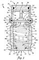
- FIG. 1 is a cross section of an embodiment of a sanitary valve assembly
- FIG. 2 is an exploded view of the cross section of the embodiment of the valve assembly of FIG. 1 and showing the valve assembly in its separable sections to allow cleaning of the valve while it is in use on a substrate;
- FIG. 3 is a top plan view of the guide cylinder of the valve assembly of the one embodiment of FIG. 1 ;
- FIG. 4 is cross-section view of the guide cylinder taken along line 4 - 4 of FIG. 3 ;
- FIG. 5 is a top plan view of a second embodiment of a sanitary valve assembly.
- FIG. 6 is a side plan view of the second embodiment of the sanitary valve showing the action of the handle of the sanitary valve assembly shown in FIG. 5 .
- FIG. 7 is a cross-section view of the second embodiment of the sanitary valve assembly shown in FIG. 5 taken along line 7 - 7 .
- valve assembly 10 comprising a valve body or a bottom body 20 and a pressure release body or top body 30 .
- the valve body 20 and the pressure release body 30 are generally cylindrical in shape and may be made of any suitable material including, without limitation, metal such as steel, or plastic such as polycarbonate depending on the application needed for the valve assembly 10 .
- the valve body 20 is generally cylindrical and hollow and has a top opening 21 and a bottom opening 22 with a continuous sidewall 22 a connecting said valve body top opening 21 and said valve body bottom opening 22 .
- the pressure release body 30 is generally cylindrical and hollow and has a top opening 31 and bottom opening 32 with a continuous sidewall 32 a connecting said pressure release body top opening 31 and said pressure release body bottom opening 32 .
- the valve body top opening 21 is connected to the pressure release body bottom opening 32 by a connecting means 86 such as a clamp, a brace, a collar, a band, or any other suitable means of connection.
- the valve body 20 has a bottom or bottom surface 23 that is comprised of a valve seat 24 , a bottom annular lip 25 and a bottom annular groove 26 .
- the bottom surface 23 contains a port 50 that communicates from the outside of the valve body 20 to the interior or passageway 51 of the valve body 20 .
- the bottom annular lip 25 provides a means of connecting the valve body 20 and therefore the valve assembly 10 to a substrate or vessel, such as a container or other pressurized or non-pressurized structure.
- the bottom annular groove 26 holds an O-ring or gasket creating a sealing engagement between a substrate and the valve assembly 10 or the valve body 20 .
- the valve body top surface 27 is comprised of a top annular lip 28 and a top annular groove 29 .
- the interior side wall 52 of the valve body 20 has a plurality of threads 53 extending from the valve body top opening 21 toward the valve body bottom opening 22 .
- the interior 51 of the valve body 20 is comprised of a guide cylinder 60 a cap ring 70 and a means of creating force or spring 80 between the cap ring 70 and the guide cylinder 60 .
- a spring comprises force means 80 and any other suitable means such as a spring loaded cylinder may be substituted.
- the guide cylinder 60 within the valve body 20 is comprised of a round bottom surface 61 that fills the port 50 and is generally flush with the valve body bottom surface 23 ; an annular second level surface 62 with a diameter larger than the round bottom surface 61 having an annular groove 63 with a means for creating a seal 64 such as an O-ring or gasket that is in contact with the valve seat 24 ; and a top surface 65 having extending therefrom, arcuate portions side walls 66 a - d of the guide cylinder 60 which are spaced apart by voids 67 a - d .
- the arcuate portions 66 interior side walls 68 and top surface 65 receive the spring 80 , to bias guide cylinder 60 against valve seat 24 .
- the arcuate portions 66 exterior side walls 69 mate against the interior side wall 52 of the valve body 20 .
- the cap ring 70 is a cylindrical tube having an outer surface 71 and an inner surface 72 .
- the outer surface 71 of the cap ring 70 has threads 73 which compliment the thread 53 on the interior side wall 52 of the valve body 20 .
- the cap ring 70 can move up or down with respect to valve interior surface 51 by turning the cap ring 70 clockwise or counterclockwise as required by threads 53 and 73 .
- the cap ring 70 contains a screw void 74 that extends from the inner surface 72 to the outer surface 71 .
- a screw 75 is placed within the screw void 74 from the inner surface 72 toward the outer surface 71 .
- the screw 75 is used to secure the cap ring 70 in a given position by tightening the screw 75 against interior side wall 52 of the valve body 20 .
- the cap ring 70 has a seat 76 which receives the top portion of the spring 80 .
- the amount of pressure required to move the guide cylinder 60 such that the second surface 62 of the guide cylinder 60 is unseated from the valve seat 24 can be either decreased or increased by altering the force of the means of creating force 80 .
- the force created by the spring 80 is increased or decreased by moving the cap ring 70 either towards the bottom opening 22 of the valve body 20 or towards the top opening 21 of the valve body 20 .
- the cap ring 70 moves by turning the cap ring 70 on threads 53 on the interior surface 51 of the valve body 20 .
- Compliment threads 73 on the outer surface 71 of the cap ring 70 operate such that turning of the cap ring 70 either clockwise or counterclockwise moves the cap ring 70 towards the bottom opening 22 of the valve body 20 thereby increasing the force on the guide cylinder 60 or moves the cap ring 70 towards the top opening 21 of the valve body 20 thereby decreasing the force on the guide cylinder 60 .
- the pressure release body 30 with a top opening 31 and a bottom opening 32 .
- the bottom opening 32 of the pressure release body 30 has a bottom annular lip 33 and a bottom annular groove 34 .
- the bottom annular groove 34 of the pressure release body 30 aligns with the top annular groove 29 of the valve body 20 such that a means for creating a sealing engagement 83 , such as an O-ring or gasket is placed between the bottom annular groove 34 of the pressure release body 30 and the top annular groove 29 of the valve body 20 .
- a stop bar 35 extends diametrically across interior side walls 36 of the pressure release body 30 .
- the stop bar 35 is secured to the interior side wall 36 of the pressure release body 30 .
- the width of the stop bar 35 does not extend laterally but allows void areas between the stop bar 35 and the side wall 36 to allow matter and gas to flow from the bottom opening 32 of the pressure release body 30 through the top opening 31 of the pressure release body 30 .
- the stop bar 35 has a void 37 which may be any shape or size but which is shown as being circular.
- the bottom annular lip 33 of the pressure release body 30 aligns with the top annular lip 28 of the valve body 20 .
- a connecting means 86 for securing the pressure release body 30 to the valve body 20 is attached or connected to the aligned annular lips 33 , 28 , the connecting means 86 could be a clamp or a band or a collar or a brace or any other suitable means.
- the connecting means 86 is removable allowing the pressure release body 30 and the valve body 20 to be separated.
- the pressure release body 30 and the valve body 20 create an alignment such that the interior of the valve body 51 directly communicates with the interior of the pressure release body 38 such that the flow of matter entering the valve assembly 10 through the port 50 can move unobstructed through the valve body 20 and the pressure release body 30 and exit the top opening 31 of the pressure release body 30 .
- a seal cap 90 is fitted on the top opening 31 of the pressure release body 30 .
- the seal cap 90 can fit into the interior 38 of the pressure release body 30 or can fit like a cap covering the top opening 31 of the pressure release body 30 and extending over a portion of the exterior surface 39 of the pressure release body 30 .
- An annular groove 91 is provided on surface 92 of the seal cap 90 which is frictionally fitted inside of the top opening 31 of the pressure release body 30 .
- a means for creating a sealing engagement 93 is placed within the annular groove 91 of the seal cap 90 . When the seal cap 90 is placed within the top opening 31 of the pressure release body 30 a frictional seal is created between the means for creating of sealing engagement 93 and the interior side wall 36 of the pressure release body 30 .
- seal cap 90 was designed to extend over the top opening 31 and encircle the exterior surface 39 of the pressure release body 30 then the annular groove 91 would be placed such that the means for creating a sealing engagement 93 created a frictional seal against the exterior surface 39 of the pressure release body 30 .
- Seal cap 90 is provided with projection 95 that extends toward the bottom opening 32 of the pressure release body 30 .
- the projection 95 is a tube having a threaded inner void 95 a and is shaped to extend through void 37 of the stop bar 35 .
- the projection 95 extends through the void 37 such that the distal portion of the projection 95 is located between the stop bar 35 and the bottom opening 32 of the pressure release body 30 .
- stopping means 96 On the distal end of the projection 35 is a stopping means 96 .
- the stopping means 96 is wider in diameter than the void 37 of the stop bar 35 .
- stopping means 96 is a void threaded screw or rod inserted into the projection 95 .
- the head of the threaded screw or rod is a larger diameter than the void 37 of the stop bar 35 .
- seal cap 90 When the seal cap 90 is frictionally held in place within the top opening 31 of the pressure release body 30 , any substance which enters the valve assembly 10 through the port 50 with a pressure that is greater than the frictional force of the seal cap 90 will cause the seal cap 90 to be ejected out of the top opening 31 of the pressure release body 30 .
- the stopping means 96 of the seal cap 90 will prevent the seal cap 90 from being completely ejected from the pressure release body 30 since the stopping means 96 exceeds the size of the void 37 of the stop bar 35 . In this manner seal cap 90 provides visual cue that an over-pressure situation had occurred if it is observed that the seal cap 90 is not resting within the top opening 31 of the pressure release body 60 .
- FIGS. 5 , 6 and 7 A second embodiment, referenced in FIGS. 5 , 6 and 7 , of a valve assembly 100 as shown.
- the valve assembly 100 comprising a valve body 110 and a pressure release body 170 .
- the second embodiment as shown in FIGS. 5 , 6 and 7 show a continuous valve assembly 100 with the valve body 110 and the pressure release body 170 manufactured as one piece.
- Alternative embodiments could employ the sectioned component of the first embodiment as shown in FIG. 1 , with a separable valve body 20 ( FIG. 1 ) and pressure release body 30 ( FIG. 1 ) attached by a connecting means 86 ( FIG. 1 ).
- the valve body 110 is comprised of a top opening 111 , a bottom opening 112 and a side opening 113 .
- a continuous sidewall 112 a connects said valve body top opening 110 and said valve body bottom opening 112 and contains said valve body side opening 113 .
- the valve body 110 is generally cylindrical in shape and hollow and may be made of any suitable material including, without limitation, metal such as steel, or plastic such as polycarbonate depending on the application needed for the valve assembly 100 .
- the bottom or bottom surface 114 is comprised of a valve seat 115 , a bottom annular lip 116 , a bottom annular groove 117 and a port 118 .
- the valve seat 115 is comprised of a lower section 119 and an upper section 120 .
- the lower section 119 of the valve seat 115 has a diameter and circumference less than upper section 120 of the valve seat 115 .
- the bottom opening 112 has a diameter and circumference that is less than the lower section 119 of the valve seat 115 .
- the port 118 provides the means of communicating between the exterior of the valve assembly 100 and the interior or passageway 121 of the valve assembly such that matter or gas can move between the exterior of the valve assembly 100 and the interior 121 of the valve assembly 100 through the port 118 .
- the top or top surface 122 of the valve body 110 is comprised of an annular lip 123 and an annular groove 124 .
- the interior surface 125 of the valve body 110 has a plurality of threads or screw threads 126 extending from the top opening 111 toward the bottom opening 112 .
- Drilled into the valve body 110 is a void 127 that extends from the interior surface 125 of the valve body 110 through to the exterior surface 129 of the valve body 110 .
- the void 127 is generally of such size to permit the placement of a screw 130 or other securing means that can be adjusted from the exterior of the valve assembly 100 .
- the guide cylinder 140 is comprised of a piston 141 and a piston rod 142 .
- the piston 141 within the valve body 110 is comprised of a round bottom surface 143 that is greater in diameter and circumference than the bottom opening 112 and port 118 .
- the round bottom surface 143 has an annular groove 144 with a means for creating a seal 145 such as an O-ring or gasket that is in contact with the lower section 119 of the valve seat 115 .
- the piston 141 has an annular second level surface 146 that has a diameter equal to the diameter of the interior surface 125 of the valve body 110 .
- the piston 141 has a circular void 148 through which the piston rod 142 is attached, as shown in FIG.
- the guide cylinder 140 may have some other means by which the piston rod 142 is attached to the piston 141 .
- the round top surface 147 of the piston 141 has an annular elevated ridge 149 that supports the means of creating force or spring 180 or may have some other means by which the spring 180 is secured to the guide cylinder 140 .
- the cap ring 160 is a cylindrical tube having an outer surface 161 and an inner surface 162 .
- the outer surface 161 of the cap ring 160 has threads or screw threads 163 which compliment the threads 126 on the interior surface 125 of the valve body 110 .
- the cap ring 160 can move up or down with respect to interior surface 125 of the valve body 110 by turning the cap ring 160 clockwise or counterclockwise as required by threads 126 and 163 .
- a screw 130 or other securing means is placed within the screw void 127 to secure the cap ring 160 in a given position by tightening the screw 130 against outer surface 161 of the cap ring 160 .
- the screw 130 is protected from the exterior of the valve assembly 100 by a protective covering 131 .
- the screw 130 allows the cap ring 160 to be secured in place thereby permitting the manufacturer or the purchaser to set the compression force of the spring 180 .
- the set force is the force exerted by the spring 180 against the guide cylinder 140 and, therefore, determines the amount of exterior pressure that is required to dislodge the guide cylinder 140 from the valve seat 115 .
- the cap ring 160 has a seat 166 which receives the top portion of the spring 180 .
- the means for creating force 180 may be a compression spring, as shown in FIG. 7 , or some other means such as a spring loaded cylinder.
- the amount of external pressure required to move the guide cylinder 140 such that the piston 141 is unseated from the valve seat 115 can be either decreased or increased by altering the force of the spring 180 .
- the force of the spring 180 is increased or decreased by moving the cap ring 160 either towards the bottom opening 112 of the valve body 110 or towards the top opening 111 of the valve body 110 .
- the cap ring 160 moves by turning the cap ring 160 on threads 126 on the interior surface 125 of the valve body 110 compliment by threads 163 on the outer surface 161 of the cap ring 160 .
- the turning of the cap ring 160 either clockwise or counterclockwise moves the cap ring 160 towards the bottom opening 112 of the valve body 110 thereby increasing the force on the guide cylinder 140 or moves the cap ring 160 towards the top opening 111 of the valve body 110 thereby decreasing the force on the guide cylinder 140 .
- the pressure release body 170 is connected to the valve body 110 by the side opening 113 of the valve body 110 .
- the pressure release body 170 is generally cylindrical and hollow and has an outer opening 171 and sidewall 172 connecting the side opening 113 with the outer opening 171 .
- the pressure release body 170 may be continuous with the valve body 110 as shown in FIG. 7 in the second embodiment or may be separable as shown in FIG. 1 of the first embodiment.
- a seal cap 190 is fitted on the outer opening 171 of the pressure release body 170 .
- the seal cap 190 can fit into the interior or passageway 173 of the pressure release body 170 or can fit like a cap covering the outer opening 171 of the pressure release body and extending over a portion of the exterior surface 174 of the pressure release body 170 .
- An annular groove 192 is provided on the side surface 191 of the seal cap 190 which is frictionally fitted inside of the side opening 172 of the pressure release body 190 .
- An O-ring or gasket 193 is placed within the annular groove 192 of the seal cap 190 .
- the seal cap 190 When the seal cap 190 is placed within the side opening 171 of the pressure release body 170 a frictional seal is created between the gasket 193 and the interior surface 175 of the pressure release body 170 . If the seal cap 190 was designed to extend over the outer opening 171 and encircle the exterior surface 174 of the pressure release body 170 then the annular groove 192 would be placed such that the gasket 193 creates a frictional seal against the exterior surface 174 of the pressure release body 170 .
- a chain 194 or other means of attaching the seal cap 190 to the valve assembly 100 may be used to prevent the seal cap 190 from being lost or projected when the seal cap 190 becomes dislodged following a breach of the valve assembly 100 from pressure.
- a lid 150 is comprised of an annular lip 151 , an annular groove 152 , a circular void 153 , and a rubber washer 154 .
- the lid 150 rests on the top surface 122 of the valve body 110 .
- the annular groove 152 of the lid 150 lines up with the top annular groove 124 of the valve body 110 .
- An O-ring or gasket 155 is placed between the annular groove 152 of the lid 150 and the top annular groove 124 of the valve body 110 .
- a connecting means 156 such as a clamp, brace, band or collar, or any other suitable connecting means, is used to attach the annular lip 151 of the lid 150 to the top annular lip 123 of the valve body 110 .
- the circular void 153 is of the same diameter as the piston rod 142 such that the piston rod 142 extends through the circular void 153 and out the top surface 157 of the lid 150 .
- a rubber washer 154 or other sealing means, is attached to the top surface 157 of the lid 150 to provide a sealing engagement between the lid 150 and the piston rod 142 .
- a handle 200 is attached to the top portion of the piston rod 142 by means of a pin 201 or other securing means.
- the handle 200 as shown in FIG. 5 , is comprised of a handle rod 206 and a U-shaped locking nut 207 .
- the handle rod 206 and U-shaped locking nut 207 may alternatively be either one unit or two separable pieces.
- the U-shaped locking nut 207 has two prongs 203 , with a drilled void 202 in both of the two prongs 203 that lines up with a drilled void 204 though the top portion of the piston rod 142 .
- a pin 201 is placed through the void 202 of prongs 203 and the void 204 of the piston rod 142 to secure the handle 200 to the piston rod 142 .
- a locking means 205 secures the pin 201 in place.
- the handle 200 allows for manual disengagement of the piston 142 from the valve seat 115 in order to release external pressure from the substrate or vessel, as shown in FIG. 6 .
- the valve assembly 100 can be disassembled, inspected and cleaned while the valve assembly 100 remains attached to the substrate or vessel and without releasing the force of the spring 180 on the guide cylinder 160 .
- the interior 121 of the valve body 110 and the interior 173 of the pressure release body 170 can be accessed by removing the lid 150 and/or the seal cap 190 .
- the unseating of the piston 142 of the guide cylinder 160 from the valve seat 115 of the valve body 110 results in pressurized matter, including liquid, gas, solid particles, and other potential contaminants, entering the interior 121 of the valve body 110 and the interior 173 of the pressure release body 170 such that the seal cap 190 is ejected from the outer opening 171 of the pressure release body 170 providing a visual cue that valve assembly 100 has been breached.
- the seal cap 190 is dislodged in a non-destructive manner and can easily be reinserted into the pressure release body 170 to reuse the valve assembly 100 .
Abstract
Description
Claims (9)
Priority Applications (1)
| Application Number | Priority Date | Filing Date | Title |
|---|---|---|---|
| US12/323,107 US8061382B2 (en) | 2007-11-30 | 2008-11-25 | Sanitary valve assembly |
Applications Claiming Priority (3)
| Application Number | Priority Date | Filing Date | Title |
|---|---|---|---|
| US99148007P | 2007-11-30 | 2007-11-30 | |
| US1433607P | 2007-12-17 | 2007-12-17 | |
| US12/323,107 US8061382B2 (en) | 2007-11-30 | 2008-11-25 | Sanitary valve assembly |
Publications (2)
| Publication Number | Publication Date |
|---|---|
| US20090145487A1 US20090145487A1 (en) | 2009-06-11 |
| US8061382B2 true US8061382B2 (en) | 2011-11-22 |
Family
ID=40720380
Family Applications (1)
| Application Number | Title | Priority Date | Filing Date |
|---|---|---|---|
| US12/323,107 Active 2029-12-06 US8061382B2 (en) | 2007-11-30 | 2008-11-25 | Sanitary valve assembly |
Country Status (1)
| Country | Link |
|---|---|
| US (1) | US8061382B2 (en) |
Cited By (2)
| Publication number | Priority date | Publication date | Assignee | Title |
|---|---|---|---|---|
| US20130053801A1 (en) * | 2011-08-26 | 2013-02-28 | James W. Thomas | Mechanical leg bag release apparatus and method |
| US9410630B1 (en) * | 2013-05-06 | 2016-08-09 | Taylor Innovations Llc | Sealing member for use in non-simmering clean service relief valve |
Families Citing this family (7)
| Publication number | Priority date | Publication date | Assignee | Title |
|---|---|---|---|---|
| CN106687346B (en) * | 2014-09-10 | 2019-07-02 | 康斯博格汽车股份公司 | Tapping valve |
| CN108591550A (en) * | 2018-06-05 | 2018-09-28 | 徐育 | A kind of safety valve for water heater in portion of leaking with clearance sealing structure |
| MX2023001581A (en) * | 2018-06-07 | 2023-03-08 | The Bentley Group Ltd | Flow control valve. |
| US10933738B2 (en) * | 2018-07-19 | 2021-03-02 | Ford Global Technologies, Llc | Methods and system for a zero hysteresis valve |
| CN108758022A (en) * | 2018-08-02 | 2018-11-06 | 昆山荣兰贸易有限公司 | Check valve assembly |
| US11231118B1 (en) * | 2020-11-10 | 2022-01-25 | Hanon Systems | Integrated one way valve |
| CN115176794A (en) * | 2022-05-30 | 2022-10-14 | 五心生物科技(福建)有限公司 | Freezing storage device for low-temperature storage of umbilical cord blood stem cells |
Citations (8)
| Publication number | Priority date | Publication date | Assignee | Title |
|---|---|---|---|---|
| US2069645A (en) * | 1934-04-21 | 1937-02-02 | Cardew Cornelius Ambrose | Means for discharging water from steam engine cylinders |
| US2634748A (en) * | 1949-01-08 | 1953-04-14 | Deere & Co | Pressure regulator valve |
| US3422840A (en) * | 1966-01-17 | 1969-01-21 | Grove Valve & Regulator Co | Relief valve with resilient seal means |
| US4168723A (en) * | 1977-11-18 | 1979-09-25 | Chicago Pneumatic Tool Company | Pressure relief valve |
| US4273151A (en) * | 1979-10-04 | 1981-06-16 | The Perlick Company, Inc. | In-line relief valve |
| US4782850A (en) * | 1987-05-26 | 1988-11-08 | Fisher Controls International, Inc. | Travel stop for diaphragm regulator valve |
| US5623962A (en) * | 1995-11-03 | 1997-04-29 | Dresser Industries | Pressure relief valve |
| US6668853B2 (en) * | 2001-05-10 | 2003-12-30 | Delaware Capital Formation, Inc. | Pressure relief valve with field-replaceable high corrosion-resistant components |
-
2008
- 2008-11-25 US US12/323,107 patent/US8061382B2/en active Active
Patent Citations (8)
| Publication number | Priority date | Publication date | Assignee | Title |
|---|---|---|---|---|
| US2069645A (en) * | 1934-04-21 | 1937-02-02 | Cardew Cornelius Ambrose | Means for discharging water from steam engine cylinders |
| US2634748A (en) * | 1949-01-08 | 1953-04-14 | Deere & Co | Pressure regulator valve |
| US3422840A (en) * | 1966-01-17 | 1969-01-21 | Grove Valve & Regulator Co | Relief valve with resilient seal means |
| US4168723A (en) * | 1977-11-18 | 1979-09-25 | Chicago Pneumatic Tool Company | Pressure relief valve |
| US4273151A (en) * | 1979-10-04 | 1981-06-16 | The Perlick Company, Inc. | In-line relief valve |
| US4782850A (en) * | 1987-05-26 | 1988-11-08 | Fisher Controls International, Inc. | Travel stop for diaphragm regulator valve |
| US5623962A (en) * | 1995-11-03 | 1997-04-29 | Dresser Industries | Pressure relief valve |
| US6668853B2 (en) * | 2001-05-10 | 2003-12-30 | Delaware Capital Formation, Inc. | Pressure relief valve with field-replaceable high corrosion-resistant components |
Cited By (2)
| Publication number | Priority date | Publication date | Assignee | Title |
|---|---|---|---|---|
| US20130053801A1 (en) * | 2011-08-26 | 2013-02-28 | James W. Thomas | Mechanical leg bag release apparatus and method |
| US9410630B1 (en) * | 2013-05-06 | 2016-08-09 | Taylor Innovations Llc | Sealing member for use in non-simmering clean service relief valve |
Also Published As
| Publication number | Publication date |
|---|---|
| US20090145487A1 (en) | 2009-06-11 |
Similar Documents
| Publication | Publication Date | Title |
|---|---|---|
| US8061382B2 (en) | Sanitary valve assembly | |
| US4986502A (en) | Safety drain plug | |
| EP0007769A1 (en) | Method and apparatus for testing the setting of a valve | |
| DK2791560T3 (en) | Pressure relief valve with protective cap | |
| US5435339A (en) | Manual air relief valve | |
| US9371914B2 (en) | Pressurized fluid cylinders | |
| US4926898A (en) | Safety choke valve | |
| US7077157B2 (en) | Spring-loaded pressure relief valve, particularly for containers of pressurized fluids | |
| US9670049B2 (en) | Plastic beer keg | |
| US20100326531A1 (en) | Combination flow control valve and reverse flow check valve | |
| US5094266A (en) | Pressure release valve | |
| US20100126946A1 (en) | System and mothod for filteringeith safety features | |
| US7121158B2 (en) | Sensor insertion into an active conduit | |
| CA1317926C (en) | Non-rising stem valve assembly and method of replacing a permanent seal | |
| US4339054A (en) | Pressure relieved plug and socket cleanout assembly | |
| US20120160849A1 (en) | Vessel, in particular pressure vessel | |
| US5131275A (en) | Gas pressure gage | |
| US5803115A (en) | Valve for relieving pressure and vacuum conditions in a tank | |
| US10914425B2 (en) | Combination valve assembly with actuatable overfill relief | |
| US4452372A (en) | Closure safety device | |
| US6644515B1 (en) | Filter-valve assembly | |
| US20060266971A1 (en) | Value for portable hermetic containers | |
| US20060096908A1 (en) | Device for filtering fluids that are conveyed under a high presure | |
| WO2019012478A1 (en) | Pressure release system and apparatus | |
| US2353306A (en) | Relief valve |
Legal Events
| Date | Code | Title | Description |
|---|---|---|---|
| STCF | Information on status: patent grant |
Free format text: PATENTED CASE |
|
| FPAY | Fee payment |
Year of fee payment: 4 |
|
| MAFP | Maintenance fee payment |
Free format text: PAYMENT OF MAINTENANCE FEE, 8TH YR, SMALL ENTITY (ORIGINAL EVENT CODE: M2552); ENTITY STATUS OF PATENT OWNER: SMALL ENTITY Year of fee payment: 8 |
|
| FEPP | Fee payment procedure |
Free format text: MAINTENANCE FEE REMINDER MAILED (ORIGINAL EVENT CODE: REM.); ENTITY STATUS OF PATENT OWNER: SMALL ENTITY |
|
| FEPP | Fee payment procedure |
Free format text: 11.5 YR SURCHARGE- LATE PMT W/IN 6 MO, SMALL ENTITY (ORIGINAL EVENT CODE: M2556); ENTITY STATUS OF PATENT OWNER: SMALL ENTITY |
|
| MAFP | Maintenance fee payment |
Free format text: PAYMENT OF MAINTENANCE FEE, 12TH YR, SMALL ENTITY (ORIGINAL EVENT CODE: M2553); ENTITY STATUS OF PATENT OWNER: SMALL ENTITY Year of fee payment: 12 |
|
| AS | Assignment |
Owner name: CUSTOM METALCRAFT, INC., MISSOURI Free format text: ASSIGNMENT OF ASSIGNORS INTEREST;ASSIGNORS:DEBORAH N. HOLDEN AS PERSONAL REPRESENTATIVE OF THE ESTATE OF DWAYNE HOLDEN;CECILY L. LANEY SOLE DESCENDANTS OF DECEDENT GERALD GLASS;TRAVIS B. GLASS SOLE DESCENDANTS OF DECEDENT GERALD GLASS;AND OTHERS;SIGNING DATES FROM 20231112 TO 20231124;REEL/FRAME:065817/0648 Owner name: TANK HOLDING CORP., MINNESOTA Free format text: ASSIGNMENT OF ASSIGNORS INTEREST;ASSIGNOR:CUSTOM METALCRAFT, INC.;REEL/FRAME:065817/0945 Effective date: 20231113 |
|
| AS | Assignment |
Owner name: ANTARES CAPITAL LP, AS COLLATERAL AGENT, ILLINOIS Free format text: SECURITY INTEREST;ASSIGNOR:TANK HOLDING CORP.;REEL/FRAME:065984/0768 Effective date: 20231229 |