US8062048B2 - Electrical connector with pivotally movable cover - Google Patents
Electrical connector with pivotally movable cover Download PDFInfo
- Publication number
- US8062048B2 US8062048B2 US12/607,081 US60708109A US8062048B2 US 8062048 B2 US8062048 B2 US 8062048B2 US 60708109 A US60708109 A US 60708109A US 8062048 B2 US8062048 B2 US 8062048B2
- Authority
- US
- United States
- Prior art keywords
- housing
- cover
- electrical connector
- electronic module
- pair
- Prior art date
- Legal status (The legal status is an assumption and is not a legal conclusion. Google has not performed a legal analysis and makes no representation as to the accuracy of the status listed.)
- Expired - Fee Related
Links
Images


Classifications
-
- H—ELECTRICITY
- H01—ELECTRIC ELEMENTS
- H01R—ELECTRICALLY-CONDUCTIVE CONNECTIONS; STRUCTURAL ASSOCIATIONS OF A PLURALITY OF MUTUALLY-INSULATED ELECTRICAL CONNECTING ELEMENTS; COUPLING DEVICES; CURRENT COLLECTORS
- H01R12/00—Structural associations of a plurality of mutually-insulated electrical connecting elements, specially adapted for printed circuits, e.g. printed circuit boards [PCB], flat or ribbon cables, or like generally planar structures, e.g. terminal strips, terminal blocks; Coupling devices specially adapted for printed circuits, flat or ribbon cables, or like generally planar structures; Terminals specially adapted for contact with, or insertion into, printed circuits, flat or ribbon cables, or like generally planar structures
- H01R12/70—Coupling devices
- H01R12/82—Coupling devices connected with low or zero insertion force
- H01R12/85—Coupling devices connected with low or zero insertion force contact pressure producing means, contacts activated after insertion of printed circuits or like structures
- H01R12/88—Coupling devices connected with low or zero insertion force contact pressure producing means, contacts activated after insertion of printed circuits or like structures acting manually by rotating or pivoting connector housing parts
Definitions
- the present invention generally relates to an electrical connector which connects an electronic module to a printed circuit board, and more particularly to an electrical connector with a rotateable cover which provides for the locking and unlocking of the electronic module from the connector.
- a conventional electrical connector for interconnecting an electronic module or an IC package or an electronic card with a printed circuit board commonly comprises an insulative base section, a plurality of contacts received in the insulative base section and a cover pivotally attached to the insulative base section.
- the cover defines a receiving space for receiving the electronic module.
- the connector is in an unlocking status, the electronic module is inserted into the receiving space of the cover.
- the cover is rotated and moves towards the insulative base section with the electronic module thereon moving together with the cover and electrically and mechanically connecting the contacts of the connector.
- the cover which is usually made from a piece of metal sheet, is required to be designed consistently with the shape of the electronic module.
- the cover should be opened at a large angle with respect to the base section which will occupy a large space.
- An electrical connector in accordance with the present invention is structured for connecting an electronic module with a printed circuit board.
- the electrical connector comprises an insulative housing defining a receiving space, a plurality of contacts received in the housing and a cover rotatablely attached to the housing.
- the housing forms a base and a pair of lateral walls extending from the base. Each lateral wall has a distal end portion.
- the housing defines an opening between the two distal end portions and opposite to the base, from which the electronic module can be inserted into the receiving space.
- a plurality of contacts are received in the base, each contact comprising a contact portion extending into the receiving space and a tail portion extending opposite to the contact portion for terminating to the printed circuit board.
- a cover is rotatablely attached to the end portions of the lateral walls of the insulative housing and is pivotally movable from an unlocked position for permitting insertion and removal of the electronic module from the housing to a locked position for the contact portions to electrically connect with the electronic module and for the cover and the housing to sandwich the electronic module therebetween.
- FIG. 1 is a perspective view of an electrical connector in accordance with the present invention and an electronic module assembly
- FIG. 2 is an exploded, perspective view of the electrical connector shown in FIG. 1 ;
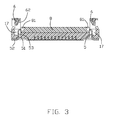
- FIG. 3 is a cross-section view of the electrical connector shown in FIG. 1 which is in an unlocking position;
- FIG. 4 is a cross-section view of the electrical connector shown in FIG. 1 which is in a locking position.
- an electrical connector 100 in accordance with the present invention is configured for mounting on a printed circuit board (not shown) and electrically connecting the printed circuit board with an electronic module 8 .
- the electronic module 8 shown in this embodiment has a plurality of contact pads (not shown) thereon and is housed in a plug assembly 200 .
- the electrical connector 100 comprises an insulative housing 1 , a plurality of contacts 2 received in the housing 1 , a pair of metal/locking ears 5 assembled on the insulative housing 1 , and a cover 3 with an actuation wedge or locking head 6 thereon pivotally attached on the insulative housing 1 .
- both the insulative housing 1 and the cover 3 are configured in U-shape and the cover 3 can be formed from a piece of metal sheet.
- the U-shaped, insulative housing 1 comprises an elongated base 10 and a pair of lateral walls 11 extending from opposite ends of the elongated base 10 with a receiving space 12 defined therebetween.
- the elongated base 10 provides a plurality of contact receiving channels (not labeled) for the contacts 2 extending therethrough, respectively.
- Each contact 2 has a contact portion 22 exposed to the receiving space for electrically and mechanically connecting with the contact pad of the electronic module 8 of the plug assembly 200 and a solder tail 21 extending out of the insulative housing 1 .
- Each lateral wall 11 defines a slit 16 adjacent to the elongated base 10 for receiving therein the metal ear 5 and a slot 17 above the slit 16 , which communicates with the receiving space 12 .
- An end portion 112 is formed at a free end of the lateral wall 11 and extends opposite to the elongated base 10 .
- Each end portion 112 has a hinge formed on an outside face thereof for assembling with the cover 3
- the cover 3 comprises a U-shaped body plate 31 and a front plate 32 extending perpendicularly from a forward edge of the U-shaped body plate 31 .
- the U-shaped body plate 31 provides a pair of pivot portions 33 on two distal free ends thereof Each pivot portion 33 defines therethrough a pivot hole 34 for pivotally receiving the hinge 15 of the end portion 112 of the insulative housing 1 .
- the engagement between the pivot hole 34 and the hinge 15 provides a pivot point, around which the metal cover 3 can rotate from a locked position to an unlocked position or vice verse.
- a finger access portion 37 is provided on the front plate 32 of the cover for user's manipulation, such as releasing the cover 3 from the locked position to the unlocked position.
- the front plate 32 defines a pair of cutouts 36 at opposite sides of the finger access portion 37 for engaging with protrusions 14 formed on the elongated base 10 so that securing the cover 3 on the insulative housing 1 when the cover 3 is at the locked position.
- the locking structure on the cover and the housing could be any other types known to the person in the art.
- the metal ear 5 employed in the present invention is for either facilitating mounting the connector 100 on the printed circuit board or for locking the electronic module 8 on the connector 100 .
- the metal ear 5 includes a body portion 51 with barbs formed thereon for fitting in the slit 16 , a solder pad 52 extending beyond a bottom of the housing 1 for soldering to the printed circuit board, and a resilient tab 53 extending from the body portion 51 and moveably received in the slot 17 .
- a pair of actuation wedge 6 are attached to the cover 3 by press fitting wedge portions 61 of the actuation wedge 6 into the holes 35 of the cover 3 . Understandably, the actuation wedge 6 can be also integratedly formed with the cover via methods known to the person having ordinary skill in the art.
- the metal ear 5 received in the housing 1 with the resilient tab 53 exposed in the slot 17 .
- the cover 3 is driven to rotate around the pivot hinge 15 and move towards the housing 1 .
- the resilient tab 53 of the metal ear 5 is pressed by the actuation wedge 6 , moves towards the receiving space 12 , and finally engages with a groove 81 of the electronic module 8 to thereby locking the module 8 on the connector. Understandably, in the unlocking position, the electronic module 8 can be assembled to or removed from the connector.
Abstract
Description
Claims (20)
Applications Claiming Priority (3)
| Application Number | Priority Date | Filing Date | Title |
|---|---|---|---|
| TW97219172U | 2008-10-28 | ||
| TW97219172 | 2008-10-28 | ||
| TW097219172U TWM358427U (en) | 2008-10-28 | 2008-10-28 | Electrical connector |
Publications (2)
| Publication Number | Publication Date |
|---|---|
| US20100105236A1 US20100105236A1 (en) | 2010-04-29 |
| US8062048B2 true US8062048B2 (en) | 2011-11-22 |
Family
ID=42117937
Family Applications (1)
| Application Number | Title | Priority Date | Filing Date |
|---|---|---|---|
| US12/607,081 Expired - Fee Related US8062048B2 (en) | 2008-10-28 | 2009-10-28 | Electrical connector with pivotally movable cover |
Country Status (2)
| Country | Link |
|---|---|
| US (1) | US8062048B2 (en) |
| TW (1) | TWM358427U (en) |
Cited By (5)
| Publication number | Priority date | Publication date | Assignee | Title |
|---|---|---|---|---|
| US20100291785A1 (en) * | 2009-05-12 | 2010-11-18 | Hon Hai Precision Industry Co., Ltd. | Elelctrical connector with a cover rotatably assembled on a housing |
| US20120302082A1 (en) * | 2011-05-24 | 2012-11-29 | Hon Hai Precision Industry Co., Ltd. | Electrical connector having retention-plate to be released by inward pressing about a pivot |
| US20140179129A1 (en) * | 2012-12-21 | 2014-06-26 | Avago Technologies General Ip (Singapore) Pte. Ltd. | Methods, apparatuses and systems for mid-plane mounting parallel optical communications modules on circuit boards |
| US9105500B2 (en) | 2012-07-13 | 2015-08-11 | International Business Machines Corporation | Non-hermetic sealed multi-chip module package |
| US20220029320A1 (en) * | 2018-11-28 | 2022-01-27 | Fujikura Ltd. | Cable and image transmission system |
Families Citing this family (1)
| Publication number | Priority date | Publication date | Assignee | Title |
|---|---|---|---|---|
| TWM360483U (en) * | 2008-09-30 | 2009-07-01 | Hon Hai Prec Ind Co Ltd | Electrical connector |
Citations (20)
| Publication number | Priority date | Publication date | Assignee | Title |
|---|---|---|---|---|
| US5813878A (en) * | 1995-12-28 | 1998-09-29 | Hirose Electric Co., Ltd. | Surface contact card connector |
| US6210193B1 (en) * | 1998-04-03 | 2001-04-03 | Molex Incorporated | Card reader connector |
| US20030129872A1 (en) * | 2002-01-07 | 2003-07-10 | Tolmie Bernard R. | Hybrid connector system and method |
| US20040067673A1 (en) * | 2002-09-17 | 2004-04-08 | Japan Aviation Electronics Industry, Limited | Thin-profile connector having a cover which can be readily operated and reliably locked in a closed state |
| US6890203B2 (en) * | 2002-04-09 | 2005-05-10 | Japan Aviation Electronics Industry, Limited | Card connector reduced in operating force |
| US6971919B1 (en) * | 2005-02-07 | 2005-12-06 | Huang-Chou Huang | Memory card connector |
| US20060057893A1 (en) * | 2004-09-15 | 2006-03-16 | Japan Aviation Electronics Industry, Limited | Card connector prevented from short-circuiting between a ground line and a signal line |
| US7156690B2 (en) * | 2002-01-07 | 2007-01-02 | Bernard R Tolmie | Extruded connector without channel insulating layer |
| US7160129B2 (en) * | 2004-07-16 | 2007-01-09 | Molex Incorporated | Memory card connector with hinged cover |
| CN2886854Y (en) | 2005-12-09 | 2007-04-04 | 达昌电子科技(苏州)有限公司 | Electronic card connector structure |
| US7220148B2 (en) * | 2005-10-21 | 2007-05-22 | Advanced Connectek Inc. | SIM card connector with locking arrangement |
| CN200944458Y (en) | 2006-03-05 | 2007-09-05 | 达昌电子科技(苏州)有限公司 | Insulating base of card connector |
| US7270559B1 (en) * | 2006-11-09 | 2007-09-18 | Jess-Link Products Co., Ltd. | Electrical card connector including a locking mechanism |
| US20080038939A1 (en) * | 2006-08-08 | 2008-02-14 | Hon Hai Precision Ind. Co., Ltd. | Board-to-board electrical connector assembly |
| US7371095B2 (en) * | 2006-08-03 | 2008-05-13 | Japan Aviation Electronics Industry, Limited | Connector easily adapted to miniaturization |
| US7404727B1 (en) * | 2007-03-02 | 2008-07-29 | Cheng Uei Precision Industry Co., Ltd. | Memory card connector |
| US7422462B2 (en) * | 2006-07-14 | 2008-09-09 | Advanced Connectek Inc. | Connector |
| US7435119B2 (en) * | 2006-10-30 | 2008-10-14 | Hon Hai Precision Ind. Co., Ltd. | Electrical card connector background of the invention |
| US7442064B2 (en) * | 2006-11-02 | 2008-10-28 | Yazaki Corporation | Board connecting body |
| US7491092B2 (en) * | 2007-01-22 | 2009-02-17 | Hon Hai Precision Ind. Co., Ltd. | Card edge connector with durable key |
-
2008
- 2008-10-28 TW TW097219172U patent/TWM358427U/en not_active IP Right Cessation
-
2009
- 2009-10-28 US US12/607,081 patent/US8062048B2/en not_active Expired - Fee Related
Patent Citations (22)
| Publication number | Priority date | Publication date | Assignee | Title |
|---|---|---|---|---|
| US5813878A (en) * | 1995-12-28 | 1998-09-29 | Hirose Electric Co., Ltd. | Surface contact card connector |
| US6210193B1 (en) * | 1998-04-03 | 2001-04-03 | Molex Incorporated | Card reader connector |
| US20030129872A1 (en) * | 2002-01-07 | 2003-07-10 | Tolmie Bernard R. | Hybrid connector system and method |
| US6821146B2 (en) * | 2002-01-07 | 2004-11-23 | Bernard R. Tolmie | Hybrid connector system and method |
| US7156690B2 (en) * | 2002-01-07 | 2007-01-02 | Bernard R Tolmie | Extruded connector without channel insulating layer |
| US6890203B2 (en) * | 2002-04-09 | 2005-05-10 | Japan Aviation Electronics Industry, Limited | Card connector reduced in operating force |
| US7063552B2 (en) * | 2002-09-17 | 2006-06-20 | Japan Aviation Electronics Industry, Limited | Thin-profile connector having a cover which can be readily operated and reliably locked in a closed state |
| US20040067673A1 (en) * | 2002-09-17 | 2004-04-08 | Japan Aviation Electronics Industry, Limited | Thin-profile connector having a cover which can be readily operated and reliably locked in a closed state |
| US7160129B2 (en) * | 2004-07-16 | 2007-01-09 | Molex Incorporated | Memory card connector with hinged cover |
| US20060057893A1 (en) * | 2004-09-15 | 2006-03-16 | Japan Aviation Electronics Industry, Limited | Card connector prevented from short-circuiting between a ground line and a signal line |
| US6971919B1 (en) * | 2005-02-07 | 2005-12-06 | Huang-Chou Huang | Memory card connector |
| US7220148B2 (en) * | 2005-10-21 | 2007-05-22 | Advanced Connectek Inc. | SIM card connector with locking arrangement |
| CN2886854Y (en) | 2005-12-09 | 2007-04-04 | 达昌电子科技(苏州)有限公司 | Electronic card connector structure |
| CN200944458Y (en) | 2006-03-05 | 2007-09-05 | 达昌电子科技(苏州)有限公司 | Insulating base of card connector |
| US7422462B2 (en) * | 2006-07-14 | 2008-09-09 | Advanced Connectek Inc. | Connector |
| US7371095B2 (en) * | 2006-08-03 | 2008-05-13 | Japan Aviation Electronics Industry, Limited | Connector easily adapted to miniaturization |
| US20080038939A1 (en) * | 2006-08-08 | 2008-02-14 | Hon Hai Precision Ind. Co., Ltd. | Board-to-board electrical connector assembly |
| US7435119B2 (en) * | 2006-10-30 | 2008-10-14 | Hon Hai Precision Ind. Co., Ltd. | Electrical card connector background of the invention |
| US7442064B2 (en) * | 2006-11-02 | 2008-10-28 | Yazaki Corporation | Board connecting body |
| US7270559B1 (en) * | 2006-11-09 | 2007-09-18 | Jess-Link Products Co., Ltd. | Electrical card connector including a locking mechanism |
| US7491092B2 (en) * | 2007-01-22 | 2009-02-17 | Hon Hai Precision Ind. Co., Ltd. | Card edge connector with durable key |
| US7404727B1 (en) * | 2007-03-02 | 2008-07-29 | Cheng Uei Precision Industry Co., Ltd. | Memory card connector |
Cited By (8)
| Publication number | Priority date | Publication date | Assignee | Title |
|---|---|---|---|---|
| US20100291785A1 (en) * | 2009-05-12 | 2010-11-18 | Hon Hai Precision Industry Co., Ltd. | Elelctrical connector with a cover rotatably assembled on a housing |
| US8360794B2 (en) * | 2009-05-12 | 2013-01-29 | Hon Hai Precision Ind. Co., Ltd | Electrical connector having a metal shell with locking tabs extending into a recess |
| US20120302082A1 (en) * | 2011-05-24 | 2012-11-29 | Hon Hai Precision Industry Co., Ltd. | Electrical connector having retention-plate to be released by inward pressing about a pivot |
| US8342871B2 (en) * | 2011-05-24 | 2013-01-01 | Hon Hai Precision Ind. Co., Ltd | Socket connector having a housing with a latching block and a retention plate with a latching arm |
| US9105500B2 (en) | 2012-07-13 | 2015-08-11 | International Business Machines Corporation | Non-hermetic sealed multi-chip module package |
| US20140179129A1 (en) * | 2012-12-21 | 2014-06-26 | Avago Technologies General Ip (Singapore) Pte. Ltd. | Methods, apparatuses and systems for mid-plane mounting parallel optical communications modules on circuit boards |
| US9106027B2 (en) * | 2012-12-21 | 2015-08-11 | Avago Technologies General Ip (Singapore) Pte. Ltd. | Methods, apparatuses and systems for mid-plane mounting parallel optical communications modules on circuit boards |
| US20220029320A1 (en) * | 2018-11-28 | 2022-01-27 | Fujikura Ltd. | Cable and image transmission system |
Also Published As
| Publication number | Publication date |
|---|---|
| TWM358427U (en) | 2009-06-01 |
| US20100105236A1 (en) | 2010-04-29 |
Similar Documents
| Publication | Publication Date | Title |
|---|---|---|
| US7780476B2 (en) | Electrical card connector | |
| US7112095B2 (en) | Card connector | |
| US7063559B2 (en) | Flexible printed circuit electrical connector | |
| US7637787B2 (en) | Audio jack connector | |
| US8062048B2 (en) | Electrical connector with pivotally movable cover | |
| US7070430B2 (en) | Electrical card connector having an eject mechanism | |
| US6478630B1 (en) | Electrical card connector having polarization mechanism | |
| US7033208B1 (en) | Flexible printed circuit connector | |
| WO2012075014A2 (en) | Card connector | |
| US7097475B2 (en) | Electrical card connector with door | |
| JP3368465B2 (en) | IC card connector | |
| US7247054B2 (en) | Electrical card connector | |
| US6475026B1 (en) | Flat flexible cable connector | |
| US6059596A (en) | Zero insertion force socket | |
| US7234966B2 (en) | IC card connector equipped with respective cover doors and associated anti-mismating device | |
| US7563138B2 (en) | Electrical card connector with improved contacts | |
| US7588453B2 (en) | Zero insertion force connector with improved driving device | |
| JP4109978B2 (en) | FPC connector and mobile phone using the same | |
| US7789683B2 (en) | Card connector having ejecting mechanism | |
| US20070123094A1 (en) | Electrical connector | |
| US20080268683A1 (en) | Card connector | |
| US8690594B2 (en) | Electrical connector with dual retention elements | |
| US6195054B1 (en) | IC card with antenna | |
| US7867004B2 (en) | Electrical connector with improved stiffener device | |
| US7544075B2 (en) | Card connector |
Legal Events
| Date | Code | Title | Description |
|---|---|---|---|
| AS | Assignment |
Owner name: HON HAI PRECISION INDUSTRY CO., LTD.,TAIWAN Free format text: ASSIGNMENT OF ASSIGNORS INTEREST;ASSIGNOR:MA, HAO-YUN;REEL/FRAME:023432/0397 Effective date: 20091022 Owner name: HON HAI PRECISION INDUSTRY CO., LTD., TAIWAN Free format text: ASSIGNMENT OF ASSIGNORS INTEREST;ASSIGNOR:MA, HAO-YUN;REEL/FRAME:023432/0397 Effective date: 20091022 |
|
| STCF | Information on status: patent grant |
Free format text: PATENTED CASE |
|
| FPAY | Fee payment |
Year of fee payment: 4 |
|
| FEPP | Fee payment procedure |
Free format text: MAINTENANCE FEE REMINDER MAILED (ORIGINAL EVENT CODE: REM.); ENTITY STATUS OF PATENT OWNER: LARGE ENTITY |
|
| LAPS | Lapse for failure to pay maintenance fees |
Free format text: PATENT EXPIRED FOR FAILURE TO PAY MAINTENANCE FEES (ORIGINAL EVENT CODE: EXP.); ENTITY STATUS OF PATENT OWNER: LARGE ENTITY |
|
| STCH | Information on status: patent discontinuation |
Free format text: PATENT EXPIRED DUE TO NONPAYMENT OF MAINTENANCE FEES UNDER 37 CFR 1.362 |
|
| FP | Lapsed due to failure to pay maintenance fee |
Effective date: 20191122 |