US8062366B2 - Ratcheting expandable corpectomy/vertebrectomy cage - Google Patents
Ratcheting expandable corpectomy/vertebrectomy cage Download PDFInfo
- Publication number
- US8062366B2 US8062366B2 US11/620,978 US62097807A US8062366B2 US 8062366 B2 US8062366 B2 US 8062366B2 US 62097807 A US62097807 A US 62097807A US 8062366 B2 US8062366 B2 US 8062366B2
- Authority
- US
- United States
- Prior art keywords
- implantable
- implant
- teeth
- implantable member
- expandable medical
- Prior art date
- Legal status (The legal status is an assumption and is not a legal conclusion. Google has not performed a legal analysis and makes no representation as to the accuracy of the status listed.)
- Active, expires
Links
Images


Classifications
-
- A—HUMAN NECESSITIES
- A61—MEDICAL OR VETERINARY SCIENCE; HYGIENE
- A61F—FILTERS IMPLANTABLE INTO BLOOD VESSELS; PROSTHESES; DEVICES PROVIDING PATENCY TO, OR PREVENTING COLLAPSING OF, TUBULAR STRUCTURES OF THE BODY, e.g. STENTS; ORTHOPAEDIC, NURSING OR CONTRACEPTIVE DEVICES; FOMENTATION; TREATMENT OR PROTECTION OF EYES OR EARS; BANDAGES, DRESSINGS OR ABSORBENT PADS; FIRST-AID KITS
- A61F2/00—Filters implantable into blood vessels; Prostheses, i.e. artificial substitutes or replacements for parts of the body; Appliances for connecting them with the body; Devices providing patency to, or preventing collapsing of, tubular structures of the body, e.g. stents
- A61F2/02—Prostheses implantable into the body
- A61F2/30—Joints
- A61F2/44—Joints for the spine, e.g. vertebrae, spinal discs
-
- A—HUMAN NECESSITIES
- A61—MEDICAL OR VETERINARY SCIENCE; HYGIENE
- A61F—FILTERS IMPLANTABLE INTO BLOOD VESSELS; PROSTHESES; DEVICES PROVIDING PATENCY TO, OR PREVENTING COLLAPSING OF, TUBULAR STRUCTURES OF THE BODY, e.g. STENTS; ORTHOPAEDIC, NURSING OR CONTRACEPTIVE DEVICES; FOMENTATION; TREATMENT OR PROTECTION OF EYES OR EARS; BANDAGES, DRESSINGS OR ABSORBENT PADS; FIRST-AID KITS
- A61F2/00—Filters implantable into blood vessels; Prostheses, i.e. artificial substitutes or replacements for parts of the body; Appliances for connecting them with the body; Devices providing patency to, or preventing collapsing of, tubular structures of the body, e.g. stents
- A61F2/02—Prostheses implantable into the body
- A61F2/30—Joints
- A61F2/3094—Designing or manufacturing processes
- A61F2/30965—Reinforcing the prosthesis by embedding particles or fibres during moulding or dipping
-
- A—HUMAN NECESSITIES
- A61—MEDICAL OR VETERINARY SCIENCE; HYGIENE
- A61F—FILTERS IMPLANTABLE INTO BLOOD VESSELS; PROSTHESES; DEVICES PROVIDING PATENCY TO, OR PREVENTING COLLAPSING OF, TUBULAR STRUCTURES OF THE BODY, e.g. STENTS; ORTHOPAEDIC, NURSING OR CONTRACEPTIVE DEVICES; FOMENTATION; TREATMENT OR PROTECTION OF EYES OR EARS; BANDAGES, DRESSINGS OR ABSORBENT PADS; FIRST-AID KITS
- A61F2/00—Filters implantable into blood vessels; Prostheses, i.e. artificial substitutes or replacements for parts of the body; Appliances for connecting them with the body; Devices providing patency to, or preventing collapsing of, tubular structures of the body, e.g. stents
- A61F2/02—Prostheses implantable into the body
- A61F2/30—Joints
- A61F2/46—Special tools or methods for implanting or extracting artificial joints, accessories, bone grafts or substitutes, or particular adaptations therefor
- A61F2/4684—Trial or dummy prostheses
-
- A—HUMAN NECESSITIES
- A61—MEDICAL OR VETERINARY SCIENCE; HYGIENE
- A61F—FILTERS IMPLANTABLE INTO BLOOD VESSELS; PROSTHESES; DEVICES PROVIDING PATENCY TO, OR PREVENTING COLLAPSING OF, TUBULAR STRUCTURES OF THE BODY, e.g. STENTS; ORTHOPAEDIC, NURSING OR CONTRACEPTIVE DEVICES; FOMENTATION; TREATMENT OR PROTECTION OF EYES OR EARS; BANDAGES, DRESSINGS OR ABSORBENT PADS; FIRST-AID KITS
- A61F2/00—Filters implantable into blood vessels; Prostheses, i.e. artificial substitutes or replacements for parts of the body; Appliances for connecting them with the body; Devices providing patency to, or preventing collapsing of, tubular structures of the body, e.g. stents
- A61F2/02—Prostheses implantable into the body
- A61F2/28—Bones
- A61F2002/2835—Bone graft implants for filling a bony defect or an endoprosthesis cavity, e.g. by synthetic material or biological material
-
- A—HUMAN NECESSITIES
- A61—MEDICAL OR VETERINARY SCIENCE; HYGIENE
- A61F—FILTERS IMPLANTABLE INTO BLOOD VESSELS; PROSTHESES; DEVICES PROVIDING PATENCY TO, OR PREVENTING COLLAPSING OF, TUBULAR STRUCTURES OF THE BODY, e.g. STENTS; ORTHOPAEDIC, NURSING OR CONTRACEPTIVE DEVICES; FOMENTATION; TREATMENT OR PROTECTION OF EYES OR EARS; BANDAGES, DRESSINGS OR ABSORBENT PADS; FIRST-AID KITS
- A61F2/00—Filters implantable into blood vessels; Prostheses, i.e. artificial substitutes or replacements for parts of the body; Appliances for connecting them with the body; Devices providing patency to, or preventing collapsing of, tubular structures of the body, e.g. stents
- A61F2/02—Prostheses implantable into the body
- A61F2/30—Joints
- A61F2002/30001—Additional features of subject-matter classified in A61F2/28, A61F2/30 and subgroups thereof
- A61F2002/30003—Material related properties of the prosthesis or of a coating on the prosthesis
- A61F2002/3006—Properties of materials and coating materials
- A61F2002/3008—Properties of materials and coating materials radio-opaque, e.g. radio-opaque markers
-
- A—HUMAN NECESSITIES
- A61—MEDICAL OR VETERINARY SCIENCE; HYGIENE
- A61F—FILTERS IMPLANTABLE INTO BLOOD VESSELS; PROSTHESES; DEVICES PROVIDING PATENCY TO, OR PREVENTING COLLAPSING OF, TUBULAR STRUCTURES OF THE BODY, e.g. STENTS; ORTHOPAEDIC, NURSING OR CONTRACEPTIVE DEVICES; FOMENTATION; TREATMENT OR PROTECTION OF EYES OR EARS; BANDAGES, DRESSINGS OR ABSORBENT PADS; FIRST-AID KITS
- A61F2/00—Filters implantable into blood vessels; Prostheses, i.e. artificial substitutes or replacements for parts of the body; Appliances for connecting them with the body; Devices providing patency to, or preventing collapsing of, tubular structures of the body, e.g. stents
- A61F2/02—Prostheses implantable into the body
- A61F2/30—Joints
- A61F2002/30001—Additional features of subject-matter classified in A61F2/28, A61F2/30 and subgroups thereof
- A61F2002/30316—The prosthesis having different structural features at different locations within the same prosthesis; Connections between prosthetic parts; Special structural features of bone or joint prostheses not otherwise provided for
- A61F2002/30329—Connections or couplings between prosthetic parts, e.g. between modular parts; Connecting elements
- A61F2002/30469—Connections or couplings between prosthetic parts, e.g. between modular parts; Connecting elements using band clamps
-
- A—HUMAN NECESSITIES
- A61—MEDICAL OR VETERINARY SCIENCE; HYGIENE
- A61F—FILTERS IMPLANTABLE INTO BLOOD VESSELS; PROSTHESES; DEVICES PROVIDING PATENCY TO, OR PREVENTING COLLAPSING OF, TUBULAR STRUCTURES OF THE BODY, e.g. STENTS; ORTHOPAEDIC, NURSING OR CONTRACEPTIVE DEVICES; FOMENTATION; TREATMENT OR PROTECTION OF EYES OR EARS; BANDAGES, DRESSINGS OR ABSORBENT PADS; FIRST-AID KITS
- A61F2/00—Filters implantable into blood vessels; Prostheses, i.e. artificial substitutes or replacements for parts of the body; Appliances for connecting them with the body; Devices providing patency to, or preventing collapsing of, tubular structures of the body, e.g. stents
- A61F2/02—Prostheses implantable into the body
- A61F2/30—Joints
- A61F2002/30001—Additional features of subject-matter classified in A61F2/28, A61F2/30 and subgroups thereof
- A61F2002/30316—The prosthesis having different structural features at different locations within the same prosthesis; Connections between prosthetic parts; Special structural features of bone or joint prostheses not otherwise provided for
- A61F2002/30329—Connections or couplings between prosthetic parts, e.g. between modular parts; Connecting elements
- A61F2002/30476—Connections or couplings between prosthetic parts, e.g. between modular parts; Connecting elements locked by an additional locking mechanism
- A61F2002/30485—Connections or couplings between prosthetic parts, e.g. between modular parts; Connecting elements locked by an additional locking mechanism plastically deformable
-
- A—HUMAN NECESSITIES
- A61—MEDICAL OR VETERINARY SCIENCE; HYGIENE
- A61F—FILTERS IMPLANTABLE INTO BLOOD VESSELS; PROSTHESES; DEVICES PROVIDING PATENCY TO, OR PREVENTING COLLAPSING OF, TUBULAR STRUCTURES OF THE BODY, e.g. STENTS; ORTHOPAEDIC, NURSING OR CONTRACEPTIVE DEVICES; FOMENTATION; TREATMENT OR PROTECTION OF EYES OR EARS; BANDAGES, DRESSINGS OR ABSORBENT PADS; FIRST-AID KITS
- A61F2/00—Filters implantable into blood vessels; Prostheses, i.e. artificial substitutes or replacements for parts of the body; Appliances for connecting them with the body; Devices providing patency to, or preventing collapsing of, tubular structures of the body, e.g. stents
- A61F2/02—Prostheses implantable into the body
- A61F2/30—Joints
- A61F2002/30001—Additional features of subject-matter classified in A61F2/28, A61F2/30 and subgroups thereof
- A61F2002/30316—The prosthesis having different structural features at different locations within the same prosthesis; Connections between prosthetic parts; Special structural features of bone or joint prostheses not otherwise provided for
- A61F2002/30329—Connections or couplings between prosthetic parts, e.g. between modular parts; Connecting elements
- A61F2002/30476—Connections or couplings between prosthetic parts, e.g. between modular parts; Connecting elements locked by an additional locking mechanism
- A61F2002/30487—Circumferential cooperating grooves and beads on cooperating lateral surfaces of a mainly longitudinal connection
-
- A—HUMAN NECESSITIES
- A61—MEDICAL OR VETERINARY SCIENCE; HYGIENE
- A61F—FILTERS IMPLANTABLE INTO BLOOD VESSELS; PROSTHESES; DEVICES PROVIDING PATENCY TO, OR PREVENTING COLLAPSING OF, TUBULAR STRUCTURES OF THE BODY, e.g. STENTS; ORTHOPAEDIC, NURSING OR CONTRACEPTIVE DEVICES; FOMENTATION; TREATMENT OR PROTECTION OF EYES OR EARS; BANDAGES, DRESSINGS OR ABSORBENT PADS; FIRST-AID KITS
- A61F2/00—Filters implantable into blood vessels; Prostheses, i.e. artificial substitutes or replacements for parts of the body; Appliances for connecting them with the body; Devices providing patency to, or preventing collapsing of, tubular structures of the body, e.g. stents
- A61F2/02—Prostheses implantable into the body
- A61F2/30—Joints
- A61F2002/30001—Additional features of subject-matter classified in A61F2/28, A61F2/30 and subgroups thereof
- A61F2002/30316—The prosthesis having different structural features at different locations within the same prosthesis; Connections between prosthetic parts; Special structural features of bone or joint prostheses not otherwise provided for
- A61F2002/30329—Connections or couplings between prosthetic parts, e.g. between modular parts; Connecting elements
- A61F2002/30476—Connections or couplings between prosthetic parts, e.g. between modular parts; Connecting elements locked by an additional locking mechanism
- A61F2002/30495—Connections or couplings between prosthetic parts, e.g. between modular parts; Connecting elements locked by an additional locking mechanism using a locking ring
-
- A—HUMAN NECESSITIES
- A61—MEDICAL OR VETERINARY SCIENCE; HYGIENE
- A61F—FILTERS IMPLANTABLE INTO BLOOD VESSELS; PROSTHESES; DEVICES PROVIDING PATENCY TO, OR PREVENTING COLLAPSING OF, TUBULAR STRUCTURES OF THE BODY, e.g. STENTS; ORTHOPAEDIC, NURSING OR CONTRACEPTIVE DEVICES; FOMENTATION; TREATMENT OR PROTECTION OF EYES OR EARS; BANDAGES, DRESSINGS OR ABSORBENT PADS; FIRST-AID KITS
- A61F2/00—Filters implantable into blood vessels; Prostheses, i.e. artificial substitutes or replacements for parts of the body; Appliances for connecting them with the body; Devices providing patency to, or preventing collapsing of, tubular structures of the body, e.g. stents
- A61F2/02—Prostheses implantable into the body
- A61F2/30—Joints
- A61F2002/30001—Additional features of subject-matter classified in A61F2/28, A61F2/30 and subgroups thereof
- A61F2002/30316—The prosthesis having different structural features at different locations within the same prosthesis; Connections between prosthetic parts; Special structural features of bone or joint prostheses not otherwise provided for
- A61F2002/30329—Connections or couplings between prosthetic parts, e.g. between modular parts; Connecting elements
- A61F2002/30518—Connections or couplings between prosthetic parts, e.g. between modular parts; Connecting elements with possibility of relative movement between the prosthetic parts
- A61F2002/3052—Connections or couplings between prosthetic parts, e.g. between modular parts; Connecting elements with possibility of relative movement between the prosthetic parts unrestrained in only one direction, e.g. moving unidirectionally
- A61F2002/30522—Connections or couplings between prosthetic parts, e.g. between modular parts; Connecting elements with possibility of relative movement between the prosthetic parts unrestrained in only one direction, e.g. moving unidirectionally releasable, e.g. using a releasable ratchet
-
- A—HUMAN NECESSITIES
- A61—MEDICAL OR VETERINARY SCIENCE; HYGIENE
- A61F—FILTERS IMPLANTABLE INTO BLOOD VESSELS; PROSTHESES; DEVICES PROVIDING PATENCY TO, OR PREVENTING COLLAPSING OF, TUBULAR STRUCTURES OF THE BODY, e.g. STENTS; ORTHOPAEDIC, NURSING OR CONTRACEPTIVE DEVICES; FOMENTATION; TREATMENT OR PROTECTION OF EYES OR EARS; BANDAGES, DRESSINGS OR ABSORBENT PADS; FIRST-AID KITS
- A61F2/00—Filters implantable into blood vessels; Prostheses, i.e. artificial substitutes or replacements for parts of the body; Appliances for connecting them with the body; Devices providing patency to, or preventing collapsing of, tubular structures of the body, e.g. stents
- A61F2/02—Prostheses implantable into the body
- A61F2/30—Joints
- A61F2002/30001—Additional features of subject-matter classified in A61F2/28, A61F2/30 and subgroups thereof
- A61F2002/30316—The prosthesis having different structural features at different locations within the same prosthesis; Connections between prosthetic parts; Special structural features of bone or joint prostheses not otherwise provided for
- A61F2002/30329—Connections or couplings between prosthetic parts, e.g. between modular parts; Connecting elements
- A61F2002/30518—Connections or couplings between prosthetic parts, e.g. between modular parts; Connecting elements with possibility of relative movement between the prosthetic parts
- A61F2002/30523—Connections or couplings between prosthetic parts, e.g. between modular parts; Connecting elements with possibility of relative movement between the prosthetic parts by means of meshing gear teeth
- A61F2002/30525—Worm gears
-
- A—HUMAN NECESSITIES
- A61—MEDICAL OR VETERINARY SCIENCE; HYGIENE
- A61F—FILTERS IMPLANTABLE INTO BLOOD VESSELS; PROSTHESES; DEVICES PROVIDING PATENCY TO, OR PREVENTING COLLAPSING OF, TUBULAR STRUCTURES OF THE BODY, e.g. STENTS; ORTHOPAEDIC, NURSING OR CONTRACEPTIVE DEVICES; FOMENTATION; TREATMENT OR PROTECTION OF EYES OR EARS; BANDAGES, DRESSINGS OR ABSORBENT PADS; FIRST-AID KITS
- A61F2/00—Filters implantable into blood vessels; Prostheses, i.e. artificial substitutes or replacements for parts of the body; Appliances for connecting them with the body; Devices providing patency to, or preventing collapsing of, tubular structures of the body, e.g. stents
- A61F2/02—Prostheses implantable into the body
- A61F2/30—Joints
- A61F2002/30001—Additional features of subject-matter classified in A61F2/28, A61F2/30 and subgroups thereof
- A61F2002/30316—The prosthesis having different structural features at different locations within the same prosthesis; Connections between prosthetic parts; Special structural features of bone or joint prostheses not otherwise provided for
- A61F2002/30535—Special structural features of bone or joint prostheses not otherwise provided for
- A61F2002/30537—Special structural features of bone or joint prostheses not otherwise provided for adjustable
- A61F2002/3055—Special structural features of bone or joint prostheses not otherwise provided for adjustable for adjusting length
-
- A—HUMAN NECESSITIES
- A61—MEDICAL OR VETERINARY SCIENCE; HYGIENE
- A61F—FILTERS IMPLANTABLE INTO BLOOD VESSELS; PROSTHESES; DEVICES PROVIDING PATENCY TO, OR PREVENTING COLLAPSING OF, TUBULAR STRUCTURES OF THE BODY, e.g. STENTS; ORTHOPAEDIC, NURSING OR CONTRACEPTIVE DEVICES; FOMENTATION; TREATMENT OR PROTECTION OF EYES OR EARS; BANDAGES, DRESSINGS OR ABSORBENT PADS; FIRST-AID KITS
- A61F2/00—Filters implantable into blood vessels; Prostheses, i.e. artificial substitutes or replacements for parts of the body; Appliances for connecting them with the body; Devices providing patency to, or preventing collapsing of, tubular structures of the body, e.g. stents
- A61F2/02—Prostheses implantable into the body
- A61F2/30—Joints
- A61F2002/30001—Additional features of subject-matter classified in A61F2/28, A61F2/30 and subgroups thereof
- A61F2002/30316—The prosthesis having different structural features at different locations within the same prosthesis; Connections between prosthetic parts; Special structural features of bone or joint prostheses not otherwise provided for
- A61F2002/30535—Special structural features of bone or joint prostheses not otherwise provided for
- A61F2002/30593—Special structural features of bone or joint prostheses not otherwise provided for hollow
-
- A—HUMAN NECESSITIES
- A61—MEDICAL OR VETERINARY SCIENCE; HYGIENE
- A61F—FILTERS IMPLANTABLE INTO BLOOD VESSELS; PROSTHESES; DEVICES PROVIDING PATENCY TO, OR PREVENTING COLLAPSING OF, TUBULAR STRUCTURES OF THE BODY, e.g. STENTS; ORTHOPAEDIC, NURSING OR CONTRACEPTIVE DEVICES; FOMENTATION; TREATMENT OR PROTECTION OF EYES OR EARS; BANDAGES, DRESSINGS OR ABSORBENT PADS; FIRST-AID KITS
- A61F2/00—Filters implantable into blood vessels; Prostheses, i.e. artificial substitutes or replacements for parts of the body; Appliances for connecting them with the body; Devices providing patency to, or preventing collapsing of, tubular structures of the body, e.g. stents
- A61F2/02—Prostheses implantable into the body
- A61F2/30—Joints
- A61F2002/30001—Additional features of subject-matter classified in A61F2/28, A61F2/30 and subgroups thereof
- A61F2002/30316—The prosthesis having different structural features at different locations within the same prosthesis; Connections between prosthetic parts; Special structural features of bone or joint prostheses not otherwise provided for
- A61F2002/30535—Special structural features of bone or joint prostheses not otherwise provided for
- A61F2002/30594—Special structural features of bone or joint prostheses not otherwise provided for slotted, e.g. radial or meridian slot ending in a polar aperture, non-polar slots, horizontal or arcuate slots
-
- A—HUMAN NECESSITIES
- A61—MEDICAL OR VETERINARY SCIENCE; HYGIENE
- A61F—FILTERS IMPLANTABLE INTO BLOOD VESSELS; PROSTHESES; DEVICES PROVIDING PATENCY TO, OR PREVENTING COLLAPSING OF, TUBULAR STRUCTURES OF THE BODY, e.g. STENTS; ORTHOPAEDIC, NURSING OR CONTRACEPTIVE DEVICES; FOMENTATION; TREATMENT OR PROTECTION OF EYES OR EARS; BANDAGES, DRESSINGS OR ABSORBENT PADS; FIRST-AID KITS
- A61F2/00—Filters implantable into blood vessels; Prostheses, i.e. artificial substitutes or replacements for parts of the body; Appliances for connecting them with the body; Devices providing patency to, or preventing collapsing of, tubular structures of the body, e.g. stents
- A61F2/02—Prostheses implantable into the body
- A61F2/30—Joints
- A61F2002/30001—Additional features of subject-matter classified in A61F2/28, A61F2/30 and subgroups thereof
- A61F2002/30316—The prosthesis having different structural features at different locations within the same prosthesis; Connections between prosthetic parts; Special structural features of bone or joint prostheses not otherwise provided for
- A61F2002/30535—Special structural features of bone or joint prostheses not otherwise provided for
- A61F2002/30601—Special structural features of bone or joint prostheses not otherwise provided for telescopic
-
- A—HUMAN NECESSITIES
- A61—MEDICAL OR VETERINARY SCIENCE; HYGIENE
- A61F—FILTERS IMPLANTABLE INTO BLOOD VESSELS; PROSTHESES; DEVICES PROVIDING PATENCY TO, OR PREVENTING COLLAPSING OF, TUBULAR STRUCTURES OF THE BODY, e.g. STENTS; ORTHOPAEDIC, NURSING OR CONTRACEPTIVE DEVICES; FOMENTATION; TREATMENT OR PROTECTION OF EYES OR EARS; BANDAGES, DRESSINGS OR ABSORBENT PADS; FIRST-AID KITS
- A61F2/00—Filters implantable into blood vessels; Prostheses, i.e. artificial substitutes or replacements for parts of the body; Appliances for connecting them with the body; Devices providing patency to, or preventing collapsing of, tubular structures of the body, e.g. stents
- A61F2/02—Prostheses implantable into the body
- A61F2/30—Joints
- A61F2002/30001—Additional features of subject-matter classified in A61F2/28, A61F2/30 and subgroups thereof
- A61F2002/30667—Features concerning an interaction with the environment or a particular use of the prosthesis
- A61F2002/30677—Means for introducing or releasing pharmaceutical products, e.g. antibiotics, into the body
-
- A—HUMAN NECESSITIES
- A61—MEDICAL OR VETERINARY SCIENCE; HYGIENE
- A61F—FILTERS IMPLANTABLE INTO BLOOD VESSELS; PROSTHESES; DEVICES PROVIDING PATENCY TO, OR PREVENTING COLLAPSING OF, TUBULAR STRUCTURES OF THE BODY, e.g. STENTS; ORTHOPAEDIC, NURSING OR CONTRACEPTIVE DEVICES; FOMENTATION; TREATMENT OR PROTECTION OF EYES OR EARS; BANDAGES, DRESSINGS OR ABSORBENT PADS; FIRST-AID KITS
- A61F2/00—Filters implantable into blood vessels; Prostheses, i.e. artificial substitutes or replacements for parts of the body; Appliances for connecting them with the body; Devices providing patency to, or preventing collapsing of, tubular structures of the body, e.g. stents
- A61F2/02—Prostheses implantable into the body
- A61F2/30—Joints
- A61F2/30767—Special external or bone-contacting surface, e.g. coating for improving bone ingrowth
- A61F2/30771—Special external or bone-contacting surface, e.g. coating for improving bone ingrowth applied in original prostheses, e.g. holes or grooves
- A61F2002/30772—Apertures or holes, e.g. of circular cross section
-
- A—HUMAN NECESSITIES
- A61—MEDICAL OR VETERINARY SCIENCE; HYGIENE
- A61F—FILTERS IMPLANTABLE INTO BLOOD VESSELS; PROSTHESES; DEVICES PROVIDING PATENCY TO, OR PREVENTING COLLAPSING OF, TUBULAR STRUCTURES OF THE BODY, e.g. STENTS; ORTHOPAEDIC, NURSING OR CONTRACEPTIVE DEVICES; FOMENTATION; TREATMENT OR PROTECTION OF EYES OR EARS; BANDAGES, DRESSINGS OR ABSORBENT PADS; FIRST-AID KITS
- A61F2220/00—Fixations or connections for prostheses classified in groups A61F2/00 - A61F2/26 or A61F2/82 or A61F9/00 or A61F11/00 or subgroups thereof
- A61F2220/0025—Connections or couplings between prosthetic parts, e.g. between modular parts; Connecting elements
-
- A—HUMAN NECESSITIES
- A61—MEDICAL OR VETERINARY SCIENCE; HYGIENE
- A61F—FILTERS IMPLANTABLE INTO BLOOD VESSELS; PROSTHESES; DEVICES PROVIDING PATENCY TO, OR PREVENTING COLLAPSING OF, TUBULAR STRUCTURES OF THE BODY, e.g. STENTS; ORTHOPAEDIC, NURSING OR CONTRACEPTIVE DEVICES; FOMENTATION; TREATMENT OR PROTECTION OF EYES OR EARS; BANDAGES, DRESSINGS OR ABSORBENT PADS; FIRST-AID KITS
- A61F2250/00—Special features of prostheses classified in groups A61F2/00 - A61F2/26 or A61F2/82 or A61F9/00 or A61F11/00 or subgroups thereof
- A61F2250/0058—Additional features; Implant or prostheses properties not otherwise provided for
- A61F2250/0096—Markers and sensors for detecting a position or changes of a position of an implant, e.g. RF sensors, ultrasound markers
- A61F2250/0098—Markers and sensors for detecting a position or changes of a position of an implant, e.g. RF sensors, ultrasound markers radio-opaque, e.g. radio-opaque markers
-
- A—HUMAN NECESSITIES
- A61—MEDICAL OR VETERINARY SCIENCE; HYGIENE
- A61F—FILTERS IMPLANTABLE INTO BLOOD VESSELS; PROSTHESES; DEVICES PROVIDING PATENCY TO, OR PREVENTING COLLAPSING OF, TUBULAR STRUCTURES OF THE BODY, e.g. STENTS; ORTHOPAEDIC, NURSING OR CONTRACEPTIVE DEVICES; FOMENTATION; TREATMENT OR PROTECTION OF EYES OR EARS; BANDAGES, DRESSINGS OR ABSORBENT PADS; FIRST-AID KITS
- A61F2310/00—Prostheses classified in A61F2/28 or A61F2/30 - A61F2/44 being constructed from or coated with a particular material
- A61F2310/00005—The prosthesis being constructed from a particular material
- A61F2310/00011—Metals or alloys
- A61F2310/00017—Iron- or Fe-based alloys, e.g. stainless steel
-
- A—HUMAN NECESSITIES
- A61—MEDICAL OR VETERINARY SCIENCE; HYGIENE
- A61F—FILTERS IMPLANTABLE INTO BLOOD VESSELS; PROSTHESES; DEVICES PROVIDING PATENCY TO, OR PREVENTING COLLAPSING OF, TUBULAR STRUCTURES OF THE BODY, e.g. STENTS; ORTHOPAEDIC, NURSING OR CONTRACEPTIVE DEVICES; FOMENTATION; TREATMENT OR PROTECTION OF EYES OR EARS; BANDAGES, DRESSINGS OR ABSORBENT PADS; FIRST-AID KITS
- A61F2310/00—Prostheses classified in A61F2/28 or A61F2/30 - A61F2/44 being constructed from or coated with a particular material
- A61F2310/00005—The prosthesis being constructed from a particular material
- A61F2310/00011—Metals or alloys
- A61F2310/00023—Titanium or titanium-based alloys, e.g. Ti-Ni alloys
-
- A—HUMAN NECESSITIES
- A61—MEDICAL OR VETERINARY SCIENCE; HYGIENE
- A61F—FILTERS IMPLANTABLE INTO BLOOD VESSELS; PROSTHESES; DEVICES PROVIDING PATENCY TO, OR PREVENTING COLLAPSING OF, TUBULAR STRUCTURES OF THE BODY, e.g. STENTS; ORTHOPAEDIC, NURSING OR CONTRACEPTIVE DEVICES; FOMENTATION; TREATMENT OR PROTECTION OF EYES OR EARS; BANDAGES, DRESSINGS OR ABSORBENT PADS; FIRST-AID KITS
- A61F2310/00—Prostheses classified in A61F2/28 or A61F2/30 - A61F2/44 being constructed from or coated with a particular material
- A61F2310/00005—The prosthesis being constructed from a particular material
- A61F2310/00011—Metals or alloys
- A61F2310/00029—Cobalt-based alloys, e.g. Co-Cr alloys or Vitallium
-
- A—HUMAN NECESSITIES
- A61—MEDICAL OR VETERINARY SCIENCE; HYGIENE
- A61F—FILTERS IMPLANTABLE INTO BLOOD VESSELS; PROSTHESES; DEVICES PROVIDING PATENCY TO, OR PREVENTING COLLAPSING OF, TUBULAR STRUCTURES OF THE BODY, e.g. STENTS; ORTHOPAEDIC, NURSING OR CONTRACEPTIVE DEVICES; FOMENTATION; TREATMENT OR PROTECTION OF EYES OR EARS; BANDAGES, DRESSINGS OR ABSORBENT PADS; FIRST-AID KITS
- A61F2310/00—Prostheses classified in A61F2/28 or A61F2/30 - A61F2/44 being constructed from or coated with a particular material
- A61F2310/00005—The prosthesis being constructed from a particular material
- A61F2310/00179—Ceramics or ceramic-like structures
Definitions
- the present invention relates generally to the field of replacing portions of the human structural anatomy with medical implants, and more particularly relates to an expandable implant and method for replacing bone structures such as one or more vertebrae or long bones.
- FIG. 1 illustrates four vertebrae, V 1 -V 4 of a typical lumbar spine and three spinal discs, D 1 -D 3 .
- V 3 is a damaged vertebra and all or a part of V 3 could be removed to help stabilize the spine. If removed along with spinal discs D 2 and D 3 , an implant may be placed between vertebrae V 2 and V 4 . Most commonly, the implant inserted between the vertebrae is designed to facilitate fusion between remaining vertebrae. Sometimes the implant is designed to replace the function of the excised vertebra and discs. All or part of more than one vertebrae may be damaged and require removal and replacement in some circumstances.
- Implants are known in the art for use in a corpectomy procedure.
- One class of implants is sized to directly replace the vertebra or vertebrae that are being replaced.
- Another class of implants is inserted into the body in a collapsed state and then expanded once properly positioned.
- Expandable implants may be advantageous because they allow for a smaller incision when properly positioning an implant. Additionally, expandable implants may assist with restoring proper loading to the anatomy and achieving more secure fixation of the implant.
- Implants that include insertion and expansion members that are narrowly configured may also provide clinical advantages. In some circumstances, it is desirable to have vertebral endplate contacting surfaces that effectively spread loading across the vertebral endplates. Effective implants should also include a member for maintaining the desired positions, and in some situations, being capable of collapsing. Fusion implants with an opening may also be advantageous because they allow for vascularization and bone growth through all or a portion of the entire implant.
- Expandable implants may also be useful in replacing long bones or portions of appendages such as the legs and arms, or a rib or other bone that is generally longer than it is wide. Examples include, but are not limited to, a femur, tibia, fibula, humerus, radius, ulna, phalanges, clavicle, and any of the ribs.
- an expandable medical implant for supporting bone structures may have an overall implant height adjustable along a longitudinal axis and may include a first member having a first outer end, a first inner end, and a first main body extending therebetween.
- the first outer end may be configured to cooperatively engage a first bone structure, and the first main body may define the longitudinal axis.
- a second member may have a second outer end, a second inner end, and a second main body extending therebetween.
- the second outer end may be configured to cooperatively engage a second bone structure.
- the second inner end may be configured to receive the first inner end of the first member.
- the second member may be moveable along the longitudinal axis relative to the first member.
- One of the first and second main bodies may include a plurality of teeth and the other of the first and second main bodies may include at least one tooth. At least a portion of one of the first and second main bodies may be elastically deformable to selectively engage and disengage the at least one tooth and the plurality of teeth. At least one tooth and the plurality of teeth may be shaped to deform the elastically deformable portion when both increasing and when decreasing the overall implant height by moving the second member relative to the first member along the longitudinal axis.
- the implant may include a locking member configured to selectively inhibit deformation of the elastically deformable portion to prevent a change in the overall implant height.
- the locking member may be a sleeve extending about and slidable along the perimeter of the second member.
- an expandable medical implant for supporting bone structures may include a first member, a second member, and a third member.
- the first member may have a first outer end configured to cooperatively engage a first bone structure and a first inner end configured to engage the second member.
- the second member may have a second outer end configured to cooperatively engage a second bone structure and a second inner end configured to engage the first member.
- the second member may be axially moveable along the longitudinal axis relative to the first member to increase the overall implant height.
- the second member may include an elastically deformable portion that elastically deforms during the axial movement.
- the third member may be configured to selectively inhibit deformation of the elastically deformable portion to inhibit axial movement and an increase in the overall implant height.
- the second member may receive the first member, and the third member may extend about a perimeter of the second member.
- the first and second members may each include a plurality of selectively engagable teeth, and the third member may be configured to selectively maintain the plurality of selectively engagable teeth in an engaged state.
- an expandable medical implant for supporting bone structures may include an inner member having a first inner end and an opposite first outer end configured to cooperatively engage with a first bone structure.
- the first member also may include an outer surface having outwardly protruding teeth disposed thereon.
- An outer member may have a second inner end and an opposite second outer end configured to cooperatively engage with a bone structure.
- the second inner end may be configured to receive the first inner end of the inner member.
- the outer member may have an inner wall surface including inwardly protruding teeth.
- the outer member may be configured to elastically deform to selectively engage and disengage the inwardly protruding teeth between the outwardly protruding teeth during axial extension.
- the inwardly and outwardly protruding teeth are configured to engage and disengage when the outer member is axially displaced in either direction relative to the inner member.
- a locking member may be disposed about the outer member. The locking member may be sized to limit elastic deformation of the outer member.
- a method of implanting an expandable medical implant for supporting bone structures may include first, second, and third members and the first and second members may define a longitudinal axis.
- the first member may have at least one tooth
- the second member may have a plurality of teeth.
- the method may include placing the implant between the bone structures and displacing the first member along the longitudinal axis relative to a second member such that one of the first and second members elastically deforms to selectively engage and disengage the at least one tooth with the plurality of teeth.
- the third member may be associated with the first or second member to selectively inhibit elastic deformation and to secure the at least one tooth in an engaged position with the plurality of teeth.
- an expandable medical implant for supporting bone structures includes a first member, a second member, and a third member.
- the first member may have a first outer end configured to cooperatively engage a first bone structure and a first inner end configured to engage the second member.
- the second member may have a second outer end configured to cooperatively engage a second bone structure and a second inner end configured to engage the first member.
- the second member may be axially moveable along the longitudinal axis relative to the first member to increase the overall implant height.
- the third member may be configured to apply a radial load that increases frictional resistance between the first and second members to selectively inhibit axial movement and an increase in the overall implant height.
- a method of implanting an expandable medical implant for supporting bone structures may include first, second, and third members, the first and second members defining a longitudinal axis.
- the method may include the steps of placing the implant between the bone structures and displacing the first member along the longitudinal axis relative to a second member.
- the third member may be associated with the first or second member to increase frictional resistance between the first and second members and to inhibit further displacement.
- FIG. 1 is an elevation view of a segment of a lumbar spine.
- FIG. 2 is an exploded side view of an exemplary expandable implant.
- FIG. 3 is a cross-section view of an outer member of the exemplary implant shown in FIG. 2 .
- FIG. 4 is a cross-section view of a locking member of the exemplary implant shown in FIG. 2 .
- FIG. 5 is a cross-section view of the assembled exemplary implant shown in FIG. 2 in a first position.
- FIG. 5A is a cross-section view showing additional detail of the assembled exemplary implant shown in FIG. 5
- FIG. 6 is a cross-section view of the assembled exemplary implant shown in FIG. 2 in a second position.
- FIG. 7 is an elevation view of an alternative locking member.
- FIG. 8 is an elevation view of another alternative locking member.
- FIG. 9 is a cross-sectional view of another embodiment of an exemplary expandable implant.
- FIG. 10 is a cross-sectional view of yet another embodiment of an exemplary expandable implant.
- the expandable implant 100 may include an inner member 102 , an outer member 104 , and a locking member 106 , extending along a longitudinal axis L.
- the inner member 102 may be formed as a tube and may include an inner end 108 configured to cooperate with the outer member 104 , and an outer end 110 configured to cooperatively interface with a bone structure, such as a vertebral body, either through additional components such as end plates or by directly abutting the bone structure.
- a main body extends between the inner and outer ends 108 , 110 . Ridges or outwardly protruding teeth 112 may extend about the outer perimeter or surface of the inner member 102 .
- the outwardly protruding teeth 112 are outward facing protrusions that form valleys 113 therebetween.
- the outwardly protruding teeth 112 are formed as triangular shaped protrusions.
- other shapes of outwardly protruding teeth 112 may be used, including for example, frustums, rounded, truncated, or sinusoidal shaped teeth, among others.
- the outer end 110 of the inner member 102 may include a flange 116 that may abut the adjacent vertebral body, thereby distributing any loads carried by the bones over a wider surface area.
- the flange may be sized to cooperate with a standard distracter tool (not shown) that would be used to distract the expandable device once it is placed within a spinal column.
- only one flange is disposed at the outer end 110 .
- the inner member 102 may include more than one flange.
- a second flange may be formed on the inner member slightly offset from the outer end 110 of the inner member 102 . A distracter tool would then be able to fit between the two flanges to more securely hold the inner member 102 during implantation of the expandable implant 100 .
- an optional modular end plate 148 a may be disposed adjacent the outer end 110 of the inner member 102 to engage the bone structure.
- the end plates may include bone fixation features, such as for example, teeth or fins configured to engage the bone structures.
- the inner member 102 Adjacent the outer end 110 , the inner member 102 may include optional gaps or windows 114 that provide access to a hollow interior 116 (shown in FIG. 5 ).
- the windows 114 may allow graft material to be introduced into the hollow interior 116 after implantation of the expandable implant 100 .
- the windows 114 may provide access for other biological activity and vascularization.
- the outwardly protruding teeth 112 may be axially spaced apart from the inner end 108 and may be disposed centrally or toward the outer end 110 of the inner device 102 . As such, the outwardly protruding teeth 112 may be formed along any part or the outer perimeter of the inner member 102 . In some embodiments, the outwardly protruding teeth 112 may be disposed adjacent the outer end 110 in place of the shown windows 114 . Also, in some embodiments, the outwardly protruding teeth 112 may be formed of separate adjacent ridges extending radially about the perimeter of the inner member 102 as shown in FIG. 2 , or alternatively, may be one or more spirally formed teeth extending about the perimeter of the inner member 102 .
- the inner member 102 is not entirely hollow, but may be solid or alternatively, may be partially hollow. For example, it may be hollow only at the outer end 102 to provide vascularization and grafting at the interface of the vertebral body and the outer end 110 .
- FIG. 2 shows a side view
- FIG. 3 shows a cross-sectional view of the outer member 104 .
- the outer member 104 may be a tubular device having an inner end 118 , an outer end 120 , and a main body 122 .
- the inner end 118 may be configured to cooperatively receive the inner member 102
- the outer end 120 may be configured to cooperatively interface with a bone structure, either directly or through additional components, such as end plates.
- the outer member 104 includes a hollow center 124 formed by an inner wall 126 .
- the hollow center 124 is sized to receive the inner end 108 of the inner member 102 . Upward or downward movement of the inner member 102 relative to the outer member 104 increases or decreases the overall height of the expandable implant 100 .
- the main body 122 of the outer member 104 in the embodiment shown, is divided into a flexible section 128 and an optional window section 130 .
- the flexible section 128 is identified by slots 132 longitudinally extending from the inner end 118 toward the outer end 120 .
- the slots 132 divide the flexible section 128 into a plurality of cantilevered segments 134 extending from the window section 130 that are capable of elastically deforming, as is explained below.
- Each cantilevered segment 134 may include inwardly protruding teeth 136 on the inner wall 126 that radially extend inward.
- the inwardly protruding teeth 136 are sized and spaced to correspond to and mesh between the outwardly protruding teeth 112 on the inner member 102 , as discussed below with reference to FIG. 5 .
- the inwardly protruding teeth 136 are spaced apart from each other about twice the distance of the spacing of the teeth 112 on the inner member 102 .
- the teeth 136 are spaced closer to each other, or further apart from each other.
- the inwardly protruding teeth 136 are formed on the cantilevered elements 134 , when the inner and outer members 102 , 104 are assembled together, axial movement of the outer member 104 relative to the inner member 102 causes the on the cantilevered elements 134 to elastically deform so that the inwardly protruding teeth 136 alternating engage and disengage the valleys 113 , thereby ratcheting between the outwardly protruding teeth 112 of the inner member 102 .
- the teeth 112 , 136 may have a zero angle or reverse angle to allow ratcheting in a single direction.
- a locking nub 138 lies about the exterior of the perimeter of the flexible section 128 .
- the locking nub 138 orients the locking member 106 in a position to secure the cantilevered segments 134 from flexing and disengaging the inner member 102 . This reduces any chance of undesired increase or decrease of the overall height of the expandable implant 100 .
- the window section 130 includes windows 140 providing access to the interior of the expandable implant 100 after the implant is placed within a spinal column. Like the windows 114 of the inner member 102 , the windows 140 allow the introduction of grafting material, as well as access for biological activity, such as vascularization.
- a flange 142 disposed at the outer end 120 of the outer member 104 provides a wide support area to distribute loads on the bone structure. In addition, it provides a location for a standard distraction type device (not shown) to apply a distraction force to separate the inner and outer members 102 , 104 to increase the height of the expandable implant 100 .
- the outer member 104 may include more than one flange.
- an optional modular end plate 148 b may be disposed adjacent the outer end 120 of the outer member 104 to engage the bone structure.
- the slots 132 extend only about halfway along the height of the main body 122 of the outer member 104 , in other embodiments, the slots extend less than half the length or more than half of the length of the main body 122 .
- the length of the slots 132 may be partially dependent on the material and wall thickness of the outer member 104 because the slots should be long enough to allow enough elastic deformation to ratchet the inwardly protruding teeth 136 into and out of engagement with the outwardly protruding teeth 112 of the inner member.
- the locking member 106 is a sleeve configured to extend about the exterior of the outer member 104 . Sized to provide a sliding fit, the locking member 106 cooperates with the outer member 104 to allow or inhibit deflection of the cantilevered segments 134 and to allow or inhibit a change the overall height of the expandable implant 100 .
- FIG. 4 shows a cross-section of the locking member 106 .
- an interior surface 143 of the locking member 106 includes a tapering lip 144 and a recess 146 .
- the tapering lip 144 and recess 146 cooperate with the locking nub 138 to secure the locking member 106 in place about the flexible section 128 of the outer member 104 .
- the tapering lip 144 of the locking member 106 may be slid over the locking nub 138 until the locking nub 138 fits within the recess 146 .
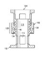
- FIGS. 5 and 6 each show cross-sectional views of the assembled expandable device 100 at different stages of implantation.
- the expandable implant 100 is in a locked condition
- the expandable implant 100 is an unlocked condition.
- the locking member 106 extends about the exterior of the outer member 104 .
- the locking member 106 slides along the outer perimeter of the outer member 104 between a locked and an unlocked position.
- the locking member 106 When in the locked position, as shown in FIG. 5 , the locking member 106 is disposed in a position to restrict substantial deflection of the cantilevered elements 134 of the outer member 104 . More specifically, the locking member 106 may be located about the flexible section 128 of the outer member 104 . In FIG. 5 , the locking member 106 is located so that the recess 146 is secured about the locking nub 138 , inhibiting any undesired movement of the locking member 106 relative to the outer member 104 . Thus, the locking member 106 also inhibits any movement of the flexible section 128 of the outer member 104 that would disengage the inwardly protruding teeth 136 from the outwardly protruding teeth 112 .
- the locking member 106 when the locking member 106 is in the unlocked position, the locking member 106 does not restrict substantial deflection of the cantilevered elements 134 .
- the locking member 106 is the unlocked position when, as shown in FIG. 6 , the locking member 106 is not disposed about the flexible section 128 .
- the locking member instead of being disposed about the flexible section 128 , the locking member is disposed about the window section 130 .
- the inwardly protruding teeth 136 of the outer member 104 are disposed between and engaged with the outwardly protruding teeth 112 of the inner member 102 .
- the outwardly protruding teeth 112 and inwardly protruding teeth 136 are formed of two flat surfaces forming the exemplary triangular teeth. These surfaces form angles ⁇ between their surfaces and a line drawn parallel to the longitudinal axis L. In one example, the angles ⁇ are equal, while in other embodiments, they are not equal, such as when the teeth have a zero angle or reverse angle. In order to provide simple ratcheting when increasing or decreasing the overall height of the implant 100 , the angles ⁇ may be between the range of 10° and 80°. In some embodiments, the angles ⁇ are within the range of 20° and 70°.
- the inwardly protruding teeth 136 are spaced apart to protrude into alternating valleys 113 formed between the outwardly protruding teeth 112 of the inner member 102 , as is shown in FIG. 6 , rather than adjacent valleys 113 . Accordingly, adjacent inwardly protruding teeth 136 on the outer member 104 mesh into non-adjacent valleys 113 formed by the outwardly protruding teeth 112 of the inner member 102 .
- inwardly protruding teeth 136 are formed on the cantilevered elements 134 , axial movement of the outer member 104 relative to the inner member 102 causes the cantilevered elements to elastically deform so that the inwardly protruding teeth 136 alternating engage and disengage the valleys 113 between the outwardly protruding teeth 112 of the inner member 102 , thereby ratcheting.
- the shape of the outwardly protruding teeth 112 and the inwardly protruding teeth 136 allow the teeth to move relative to each other along the longitudinal axis L to not only increase the overall height of the implantable member 100 , but also to decrease the overall height of the implantable member 100 .
- the expandable implant 100 may be surgically placed within a patient to engage and stabilize bone structures.
- the expandable implant is introduced through an incision in a fully retracted position.
- the expandable implant 100 is at its smallest size, thereby allowing implantation through the smallest possible incision.
- the expandable implant 100 In its fully retracted condition, the expandable implant 100 is positioned into the bone segment, such as a vertebral segment, in the space previously occupied by a vertebral body.
- the expandable implant may be positioned in place of vertebral body V 3 and the adjacent disks D 2 and D 3 .
- the locking member 106 may be axially slid to disengage the locking member 106 from the locking nub 138 of the outer member 104 , as is shown in FIG. 6 .
- a distraction tool or spreader (not shown) is inserted to engage the flanges 116 , 142 on each of the outer ends 110 , 120 to urge them apart and into engagement with the intact vertebra.
- the cantilevered segments 134 ratchet as they elastically deform and the inwardly protruding teeth 136 disengage and reengage the outwardly protruding teeth 112 . Accordingly, the inwardly protruding teeth 136 ratchet in and out from the outwardly protruding teeth 112 and change the overall height of the implant 100 .
- the locking member 106 is axially slid to cover the flexible section 128 of the outer member 104 .
- the locking member 106 forces the inwardly protruding teeth 136 in place between the outwardly protruding teeth 112 , and the tapering lip slides over the locking nub 138 and the locking nub snaps into the recess 146 .
- the locking member 106 can be axially slid off the locking nub 138 and off the flexible section 128 .
- the outer ends 110 , 120 can be brought together while the teeth 112 , 136 ratchet in a manner similar to the manner done during expansion. Once the implant is retracted a desired amount, the implant can be removed.
- a second locking nub is disposed toward the outer end 120 of the outer member 104 .
- This second locking nub may be used to securely hold the locking member 106 is the unlocked position during placement or distraction of the implant 100 .
- the interior surface 143 of the locker member 106 may have a tapered lip 144 at each end and, in some embodiments, an additional recess may be employed.
- a single recess 146 may be used to secure the locking member 106 whether it is in the locked or unlocked position.
- FIGS. 7 and 8 show alternative embodiments of the locking member 106 .
- FIG. 7 shows a locking member 150 formed of a band 152 and a gear box 154 .
- the band 152 may be formed of a biologically compatible metal or other material, and may include perforations 156 .
- the gear box 154 may include a worm-type gear 158 having teeth (not shown) that engage the perforations 156 in the band 152 .
- the gear 158 may pull the band 152 to tighten it about the exterior of the outer member 104 , thereby inhibiting deformation of the cantilevered segments 134 , and thereby maintaining the outwardly protruding teeth 112 and the inwardly protruding teeth 136 in an engaged or meshed position.
- FIG. 8 shows another alternative embodiment of a locking member.
- the locking member 160 is a clamping band.
- the locking member 160 includes a first band 162 , a second band 164 , a hinge 165 , and a fastener 166 .
- the first and second bands 162 , 164 are joined at one end by the hinge 165 .
- the other ends of the bands 162 , 164 may be bent and perforated to receive the fastener 166 .
- the fastener 166 is a bolt and nut.
- the locking member 160 includes only a single band, rather than multiple bands as shown in FIG. 8 .
- the two ends of the single band may be still joined to each other using a bolt and nut or other fastening system.
- the locking member 160 is placed about the exterior of the cantilevered segments 134 and then tightened and fastened closed to inhibit deformation of the cantilevered segments 134 , and thereby maintain the outwardly protruding teeth 112 and the inwardly protruding teeth 136 in an engaged or meshed position.
- Other fastening systems may be used, including screws, buckles, and others. It should be noted that other locking members also may be used to inhibit disengagement of the outwardly protruding teeth 112 and the inwardly protruding teeth 136 .
- FIG. 9 shows another exemplary embodiment of an outer member 170 and a locking member 172 .
- the outer member 170 and locking member 172 are similar to those disclosed above with reference to FIG. 2 , but cantilevered segments 174 of the outer member 170 are tapered so that the outer diameter of an inner end 176 is greater than the diameter of other portions of the main body.
- the locking member 172 includes a tapered inner surface 180 that matches the tapered surface of the outer member 170 . Accordingly, by sliding the locking member 172 downward over the tapering cantilevered segments 174 , the locking member 172 provides a holding force that inhibits expansion and disengagement of the outwardly protruding teeth and the inwardly protruding teeth. It should be noted that some embodiments of the outer member and locking member do not employ the locking nub 138 and the recess 146 .
- FIG. 10 shows another exemplary embodiment of an expandable implant 190 .
- the implant 190 includes an inner member 192 , an outer member 194 , and a locking member 196 .
- the inner member 192 and the outer member 194 are similar to those disclosed above with reference to FIG. 2 , but they do not include ratcheting teeth. Instead, the inner member 192 and the outer member 194 have surfaces that are relatively free of engaging protrusions and allow movement without deformation of any cantilevered segments 198 of the outer member 194 .
- the locking member 196 may be configured to secure the inner member 192 and the outer member 194 to each other by applying a radial load that causes the inner and outer members 192 , 194 to be secured to each other by friction.
- the locking member 196 may have an adjustable radius.
- the locking members 150 and 160 described with reference to FIGS. 7 and 8 may be used to securely hold the outer and inner members 192 , 194 in frictional engagement.
- Other locking members having an adjustable radius are also contemplated. Accordingly, by tightening the locking member 196 about the inner and outer members 192 , 194 , the locking member 196 provides a holding force that frictionally inhibits expansion and sliding.
- the inner member 102 is substantially solid such that while it is telescopically received within the outer member 104 , no material may be received within inner member 102 .
- the inner member 102 has been shown as telescopically received within tubular outer member 104 , it will be appreciated that in a further embodiment the respective configuration is inverted such that the cantilevered segments are provided on the inner member rather than the outer member.
- the tubular shapes may take the form of a rectangle, square, ellipse, diamond, oval, D-shape or any shape. Further, the shapes may conform and substantially match the adjacent bone or the bone structure that is being replaced.
- the definition of tubular is not intended to be limited to cylindrical but is instead intended to cover all components that may be utilized to reduce the present invention.
- the length of the device may be sized appropriate to span multiple vertebrae. Additionally, the device may find application in other orthopedic areas and the size and shape of the device may be made to substantially match the implantation site.
- the present embodiment has been illustrated as a substantially cylindrical device, it is contemplated that in certain spinal applications it is desirable that the device have a substantially D shaped cross-section as viewed from top to bottom such that the anterior portion of the device has an exterior convexly curved surface matching the anterior of the vertebral body while the posterior portion of the device is substantially flat or concave allowing it to be positioned closer to the spinal canal without protruding into the spinal canal.
- Embodiments of the implant in whole or in part may be constructed of biocompatible materials of various types.
- implant materials include, but are not limited to, non-reinforced polymers, carbon-reinforced polymer composites, PEEK and PEEK composites, shape-memory alloys, titanium, titanium alloys, cobalt chrome alloys, stainless steel, ceramics and combinations thereof.
- radiographic markers can be located on the trial instrument or implant to provide the ability to monitor and determine radiographically or fluoroscopically the location of the body in the spinal disc space.
- radiographic markers are placed to show the location of the locking member relative to the outer member.
- radiographic markers may be disposed adjacent the locking nub 138 and the recess 146 so that a physician can determine easily whether the locking member is properly located.
- the implant or individual components of the implant are constructed of solid sections of bone or other tissues.
- the implant is constructed of planks of bone that are assembled into a final configuration.
- the implant may be constructed of planks of bone that are assembled along horizontal or vertical planes through one or more longitudinal axes of the implant.
- the hollow centers 124 may contain grafting materials.
- Tissue materials include, but are not limited to, synthetic or natural autograft, allograft or xenograft, and may be resorbable or non-resorbable in nature. Examples of other tissue materials include, but are not limited to, hard tissues, connective tissues, demineralized bone matrix and combinations thereof.
- resorbable materials examples include, but are not limited to, polylactide, polyglycolide, tyrosine-derived polycarbonate, polyanhydride, polyorthoester, polyphosphazene, calcium phosphate, hydroxyapatite, bioactive glass, and combinations thereof.
- Implant may be solid, porous, spongy, perforated, drilled, and/or open.
- Osteogenic materials include, without limitation, autograft, allograft, xenograft, demineralized bone, synthetic and natural bone graft substitutes, such as bioceramics and polymers, and osteoinductive factors.
- a separate carrier to hold materials within the device can also be used. These carriers can include collagen-based carriers, bioceramic materials, such as BIOGLASS®, hydroxyapatite and calcium phosphate compositions.
- the carrier material may be provided in the form of a sponge, a block, folded sheet, putty, paste, graft material or other suitable form.
- the osteogenetic compositions may include an effective amount of a bone morphogenetic protein, transforming growth factor ⁇ 1, insulin-like growth factor 1, platelet-derived growth factor, fibroblast growth factor, LIM mineralization protein (LMP), and combinations thereof or other therapeutic or infection resistant agents, separately or held within a suitable carrier material.
- a technique of an embodiment of the invention is to first pack the interior of an unexpanded implant with material and then place one or both end members if desired.
- Access to the surgical site may be through any surgical approach that will allow adequate visualization and/or manipulation of the bone structures.
- Example surgical approaches include, but are not limited to, any one or combination of anterior, antero-lateral, posterior, postero-lateral, transforaminal, and/or far lateral approaches.
- Implant insertion can occur through a single pathway or through multiple pathways, or through multiple pathways to multiple levels of the spinal column. Minimally invasive techniques employing instruments and implants are also contemplated.
- FIG. 1 illustrates four vertebrae, V 1 -V 4 , of a typical lumbar spine and three spinal discs, D 1 -D 3 . While embodiments of the invention may be applied to the lumbar spinal region, embodiments may also be applied to the cervical or thoracic spine or between other bone structures.
Abstract
Description
Claims (34)
Priority Applications (1)
| Application Number | Priority Date | Filing Date | Title |
|---|---|---|---|
| US11/620,978 US8062366B2 (en) | 2007-01-08 | 2007-01-08 | Ratcheting expandable corpectomy/vertebrectomy cage |
Applications Claiming Priority (1)
| Application Number | Priority Date | Filing Date | Title |
|---|---|---|---|
| US11/620,978 US8062366B2 (en) | 2007-01-08 | 2007-01-08 | Ratcheting expandable corpectomy/vertebrectomy cage |
Publications (2)
| Publication Number | Publication Date |
|---|---|
| US20100249934A1 US20100249934A1 (en) | 2010-09-30 |
| US8062366B2 true US8062366B2 (en) | 2011-11-22 |
Family
ID=42785214
Family Applications (1)
| Application Number | Title | Priority Date | Filing Date |
|---|---|---|---|
| US11/620,978 Active 2027-04-09 US8062366B2 (en) | 2007-01-08 | 2007-01-08 | Ratcheting expandable corpectomy/vertebrectomy cage |
Country Status (1)
| Country | Link |
|---|---|
| US (1) | US8062366B2 (en) |
Cited By (25)
| Publication number | Priority date | Publication date | Assignee | Title |
|---|---|---|---|---|
| US20090138089A1 (en) * | 2007-11-27 | 2009-05-28 | Doubler Robert L | Corpectomy implant |
| US20100198221A1 (en) * | 2007-08-20 | 2010-08-05 | Synthes USA , LLC | Ratcheting Epiphysiodesis Plate |
| US20100287740A1 (en) * | 2007-07-12 | 2010-11-18 | Etablissements Caillau | Automatically Triggered Tightening System for an Elastic Clamping Collar |
| US20120226356A1 (en) * | 2011-03-03 | 2012-09-06 | Robert Alex Hirschl | Expandable corpectomy cage |
| US20140277509A1 (en) * | 2013-03-15 | 2014-09-18 | Spectrum Spine Ip Holdings, Llc | Expandable vertebral body replacement and methods |
| US9144503B2 (en) | 2012-10-12 | 2015-09-29 | Warsaw Orthopedic, Inc. | Expandable spinal implant system and method |
| US9211193B2 (en) | 2013-08-30 | 2015-12-15 | Aesculap Implant Systems, Llc | Prosthesis, system and method |
| US9211197B2 (en) | 2013-03-14 | 2015-12-15 | Atlas Spine, Inc. | Expandable corpectomy device |
| US9216096B2 (en) | 2010-03-16 | 2015-12-22 | Pinnacle Spine Group, Llc | Intervertebral implants and related tools |
| US9380932B1 (en) | 2011-11-02 | 2016-07-05 | Pinnacle Spine Group, Llc | Retractor devices for minimally invasive access to the spine |
| US9393130B2 (en) | 2013-05-20 | 2016-07-19 | K2M, Inc. | Adjustable implant and insertion tool |
| US9566167B2 (en) | 2013-08-22 | 2017-02-14 | K2M, Inc. | Expandable spinal implant |
| US9622876B1 (en) | 2012-04-25 | 2017-04-18 | Theken Spine, Llc | Expandable support device and method of use |
| US9681961B2 (en) | 2014-08-01 | 2017-06-20 | Warsaw Orthopedic, Inc. | Surgical instrument system and method |
| US9844446B2 (en) | 2016-05-05 | 2017-12-19 | Globus Medical, Inc. | Expandable vertebral implant |
| US9925061B2 (en) | 2013-03-14 | 2018-03-27 | Atlas Spine, Inc. | Expandable corpectomy device |
| US9968460B2 (en) | 2013-03-15 | 2018-05-15 | Medsmart Innovation Inc. | Dynamic spinal segment replacement |
| US9974663B2 (en) | 2014-10-09 | 2018-05-22 | Warsaw Orthopedic, Inc. | Spinal implant system and method |
| US10070970B2 (en) | 2013-03-14 | 2018-09-11 | Pinnacle Spine Group, Llc | Interbody implants and graft delivery systems |
| US10363142B2 (en) | 2014-12-11 | 2019-07-30 | K2M, Inc. | Expandable spinal implants |
| US10441430B2 (en) | 2017-07-24 | 2019-10-15 | K2M, Inc. | Expandable spinal implants |
| US10842651B2 (en) | 2016-06-10 | 2020-11-24 | Globus Medical, Inc. | Vertebral implants and attachment assemblies |
| USRE48719E1 (en) | 2014-10-09 | 2021-09-07 | K2M, Inc. | Expandable spinal interbody spacer and method of use |
| US11452612B2 (en) | 2014-10-09 | 2022-09-27 | Warsaw Orthopedic, Inc. | Spinal implant system and method |
| US11491028B2 (en) | 2016-02-26 | 2022-11-08 | K2M, Inc. | Insertion instrument for expandable spinal implants |
Families Citing this family (23)
| Publication number | Priority date | Publication date | Assignee | Title |
|---|---|---|---|---|
| US8088163B1 (en) | 2008-02-06 | 2012-01-03 | Kleiner Jeffrey B | Tools and methods for spinal fusion |
| US8366748B2 (en) | 2008-12-05 | 2013-02-05 | Kleiner Jeffrey | Apparatus and method of spinal implant and fusion |
| US8721723B2 (en) * | 2009-01-12 | 2014-05-13 | Globus Medical, Inc. | Expandable vertebral prosthesis |
| US9247943B1 (en) | 2009-02-06 | 2016-02-02 | Kleiner Intellectual Property, Llc | Devices and methods for preparing an intervertebral workspace |
| US9629729B2 (en) | 2009-09-18 | 2017-04-25 | Spinal Surgical Strategies, Llc | Biological delivery system with adaptable fusion cage interface |
| US9186193B2 (en) | 2009-09-18 | 2015-11-17 | Spinal Surgical Strategies, Llc | Fusion cage with combined biological delivery system |
| USD723682S1 (en) | 2013-05-03 | 2015-03-03 | Spinal Surgical Strategies, Llc | Bone graft delivery tool |
| USD750249S1 (en) | 2014-10-20 | 2016-02-23 | Spinal Surgical Strategies, Llc | Expandable fusion cage |
| US8906028B2 (en) | 2009-09-18 | 2014-12-09 | Spinal Surgical Strategies, Llc | Bone graft delivery device and method of using the same |
| US8685031B2 (en) | 2009-09-18 | 2014-04-01 | Spinal Surgical Strategies, Llc | Bone graft delivery system |
| US10973656B2 (en) | 2009-09-18 | 2021-04-13 | Spinal Surgical Strategies, Inc. | Bone graft delivery system and method for using same |
| US9173694B2 (en) | 2009-09-18 | 2015-11-03 | Spinal Surgical Strategies, Llc | Fusion cage with combined biological delivery system |
| US10245159B1 (en) | 2009-09-18 | 2019-04-02 | Spinal Surgical Strategies, Llc | Bone graft delivery system and method for using same |
| US9060877B2 (en) | 2009-09-18 | 2015-06-23 | Spinal Surgical Strategies, Llc | Fusion cage with combined biological delivery system |
| US20170238984A1 (en) | 2009-09-18 | 2017-08-24 | Spinal Surgical Strategies, Llc | Bone graft delivery device with positioning handle |
| US9402744B2 (en) | 2010-06-11 | 2016-08-02 | International Spinal Innovations, Llc | Pre-packed corpectomy device to improve fusion |
| US8771359B2 (en) * | 2010-12-01 | 2014-07-08 | Daniel Dongwahn Lee | Spinal implant device |
| US8740980B2 (en) * | 2011-01-27 | 2014-06-03 | Warsaw Orthopedic, Inc. | Expandable medical implant |
| US9289252B2 (en) | 2011-04-08 | 2016-03-22 | Paragon 28, Inc. | Orthopaedic plate and spreader apparatuses and methods |
| WO2014145982A1 (en) | 2013-03-15 | 2014-09-18 | Spectrum Spine Ip Holdings, Llc | Expandable vertebral body replacement device, system, and methods |
| USD797290S1 (en) | 2015-10-19 | 2017-09-12 | Spinal Surgical Strategies, Llc | Bone graft delivery tool |
| EP3357459A1 (en) | 2017-02-03 | 2018-08-08 | Spinal Surgical Strategies, LLC | Bone graft delivery device with positioning handle |
| US10758365B2 (en) | 2017-05-08 | 2020-09-01 | Zavation Medical Products, Llc | Expandable spinal cage assemblies for supporting bone structures |
Citations (72)
| Publication number | Priority date | Publication date | Assignee | Title |
|---|---|---|---|---|
| US409066A (en) * | 1889-08-13 | Hose-coupling | ||
| US768452A (en) * | 1904-03-24 | 1904-08-23 | Charles H Paine | Walking-stick. |
| US1390564A (en) * | 1920-01-24 | 1921-09-13 | Margaret R Elkin | Hose-clamp |
| US2120275A (en) * | 1936-09-16 | 1938-06-14 | Cowles Irving | Detachable hose coupling |
| US3073628A (en) * | 1958-10-13 | 1963-01-15 | Aeroquip Corp | Fitting |
| US3724882A (en) * | 1971-05-10 | 1973-04-03 | Ford Motor Co | Tube-to-hose connection |
| US4157715A (en) | 1977-03-25 | 1979-06-12 | Erhard Westerhoff | Intracorporal drive to produce a continuous traction or pressure and method of operating the same |
| US4401112A (en) | 1980-09-15 | 1983-08-30 | Rezaian Seyed M | Spinal fixator |
| US4657550A (en) | 1984-12-21 | 1987-04-14 | Daher Youssef H | Buttressing device usable in a vertebral prosthesis |
| US4820305A (en) | 1986-11-03 | 1989-04-11 | Harms Juergen | Place holder, in particular for a vertebra body |
| FR2636227A1 (en) | 1988-09-09 | 1990-03-16 | Fabrication Materiel Orthopedi | Inter-spinal-body device for holding a normal spacing between two vertebrae |
| US4932975A (en) | 1989-10-16 | 1990-06-12 | Vanderbilt University | Vertebral prosthesis |
| US5026373A (en) | 1988-10-17 | 1991-06-25 | Surgical Dynamics, Inc. | Surgical method and apparatus for fusing adjacent bone structures |
| DE4012622C1 (en) | 1990-04-20 | 1991-07-18 | Eska Medical Luebeck Medizintechnik Gmbh & Co, 2400 Luebeck, De | Two-part metal vertebra implant - has parts locked by two toothed racks, pre-stressed by elastic cushion between both implant parts |
| US5062850A (en) | 1990-01-16 | 1991-11-05 | University Of Florida | Axially-fixed vertebral body prosthesis and method of fixation |
| WO1992001428A1 (en) | 1990-07-24 | 1992-02-06 | Mohamed Ibrahim Rasheed | Artificial vertebra |
| EP0490159A1 (en) | 1990-12-07 | 1992-06-17 | ESKA Implants GmbH & Co. | Length adaptor for long-bones endoprosthesis |
| US5281226A (en) | 1989-03-31 | 1994-01-25 | Davydov Anatoly B | Missing portion of a tubular bone |
| US5336223A (en) | 1993-02-04 | 1994-08-09 | Rogers Charles L | Telescoping spinal fixator |
| DE19509317A1 (en) | 1995-03-15 | 1996-09-19 | Heinrich Ulrich | Spinal column implant for mounting between vertebrae |
| US5571190A (en) | 1993-08-20 | 1996-11-05 | Heinrich Ulrich | Implant for the replacement of vertebrae and/or stabilization and fixing of the spinal column |
| US5571192A (en) | 1994-07-02 | 1996-11-05 | Heinrich Ulrich | Prosthetic vertebral implant |
| US5702455A (en) | 1996-07-03 | 1997-12-30 | Saggar; Rahul | Expandable prosthesis for spinal fusion |
| US5702451A (en) | 1995-02-14 | 1997-12-30 | Biedermann; Lutz | Space holder, in particular for a vertebra or an intervertebral disk |
| US5702453A (en) | 1994-12-09 | 1997-12-30 | Sofamor Danek Group | Adjustable vertebral body replacement |
| US5723013A (en) | 1995-02-06 | 1998-03-03 | Jbs S.A. | Spacer implant for substituting missing vertebrae |
| US5776197A (en) | 1994-12-09 | 1998-07-07 | Sdgi Holdings, Inc. | Adjustable vertebral body replacement |
| WO1998046173A1 (en) | 1997-04-15 | 1998-10-22 | Synthes Ag Chur | Telescopic vertebral prosthesis |
| WO1999039665A1 (en) | 1998-02-06 | 1999-08-12 | Biedermann Motech Gmbh | Spacer with adjustable axial length |
| US5989290A (en) | 1995-05-24 | 1999-11-23 | Biedermann; Lutz | Height-adjustable artificial vertebral body |
| WO1999063913A2 (en) | 1998-06-05 | 1999-12-16 | Surgicraft Limited | Surgical implant |
| US6015436A (en) | 1996-06-07 | 2000-01-18 | Heinrich Ulrich | Implant for filling a space between vertebrae |
| WO2000023013A1 (en) | 1998-10-15 | 2000-04-27 | Synthes Ag Chur | Telescopic vertebral prosthesis |
| US6086613A (en) | 1997-12-23 | 2000-07-11 | Depuy Acromed, Inc. | Spacer assembly for use in spinal surgeries |
| WO2000045751A1 (en) | 1999-02-04 | 2000-08-10 | Synthes Ag Chur | End member for a bone fusion implant |
| US6159244A (en) | 1999-07-30 | 2000-12-12 | Suddaby; Loubert | Expandable variable angle intervertebral fusion implant |
| US6190413B1 (en) | 1998-04-16 | 2001-02-20 | Ulrich Gmbh & Co. Kg | Vertebral implant |
| US6193755B1 (en) | 1996-09-26 | 2001-02-27 | Howmedica Gmbh | Spinal cage assembly |
| US6193756B1 (en) | 1997-09-30 | 2001-02-27 | Sulzer Orthopaedie Ag | Tubular support body for bridging two vertebrae |
| EP1080703A2 (en) | 1999-09-02 | 2001-03-07 | Howmedica Osteonics Corp. | Spinal implant |
| US6296665B1 (en) | 2000-03-20 | 2001-10-02 | Electro-Biology, Inc. | Method and apparatus for spinal fixation |
| US6332895B1 (en) | 2000-03-08 | 2001-12-25 | Loubert Suddaby | Expandable intervertebral fusion implant having improved stability |
| US6344057B1 (en) | 1994-11-22 | 2002-02-05 | Sdgi Holdings, Inc. | Adjustable vertebral body replacement |
| US6352556B1 (en) | 1999-01-22 | 2002-03-05 | Signus Medizintechnik Gmbh | Vertebral column replacement body |
| EP1188424A1 (en) | 2000-08-21 | 2002-03-20 | Christos Kalaitzis | Prosthesis for replacement of a whole vertebral unit |
| US6395034B1 (en) | 1999-11-24 | 2002-05-28 | Loubert Suddaby | Intervertebral disc prosthesis |
| WO2002071986A2 (en) | 2001-03-13 | 2002-09-19 | Depuy International Ltd. | Vertebral body replacement device |
| US6454806B1 (en) | 1999-07-26 | 2002-09-24 | Advanced Prosthetic Technologies, Inc. | Spinal surgical prosthesis |
| DE20213013U1 (en) | 2002-08-24 | 2002-12-19 | Metz Stavenhagen Peter | Spine wildcard |
| US6562074B2 (en) | 2001-10-17 | 2003-05-13 | Medicinelodge, Inc. | Adjustable bone fusion implant and method |
| US20030163199A1 (en) | 2000-03-31 | 2003-08-28 | Heinrich Boehm | Variable height vertebral implant |
| US6616695B1 (en) | 1998-01-30 | 2003-09-09 | Stryker Spine | Implant for replacing a vertebra |
| US20030181980A1 (en) | 2002-03-21 | 2003-09-25 | Berry Bret M. | Vertebral body and disc space replacement devices |
| US20030191531A1 (en) | 2002-03-21 | 2003-10-09 | Berry Bret M. | Vertebral body and disc space replacement devices |
| WO2003096937A1 (en) | 2002-05-21 | 2003-11-27 | Peter Metz-Stavenhagen | Vertebral body placeholder |
| US6660038B2 (en) * | 2000-03-22 | 2003-12-09 | Synthes (Usa) | Skeletal reconstruction cages |
| US6719796B2 (en) | 1999-07-26 | 2004-04-13 | Advanced Prosthetic Technologies, Inc. | Spinal surgical prosthesis |
| US20040073314A1 (en) | 2002-03-21 | 2004-04-15 | White John L. | Vertebral body and disc space replacement devices |
| US20040153160A1 (en) | 2002-10-30 | 2004-08-05 | Carrasco Mauricio Rodolfo | Implant for vertebral replacement and restoration of the normal spinal curvature |
| US20040186569A1 (en) | 2003-03-20 | 2004-09-23 | Berry Bret M. | Height adjustable vertebral body and disc space replacement devices |
| US6796586B2 (en) * | 2001-07-09 | 2004-09-28 | Twin Bay Medical, Inc. | Barb clamp |
| WO2004089256A1 (en) | 2003-04-11 | 2004-10-21 | Mathys Medizinaltechnik Ag | Anchoring means for intervertebral implants |
| WO2004100837A1 (en) | 2003-05-14 | 2004-11-25 | Kilian Kraus | Height-adjustable implant to be inserted between vertebral bodies and corresponding handling tool |
| US20050090898A1 (en) | 2003-10-22 | 2005-04-28 | Sdgi Holdings, Inc. | Vertebral body replacement implant |
| US20050096744A1 (en) | 2003-11-05 | 2005-05-05 | Sdgi Holdings, Inc. | Compressible corpectomy device |
| US20050159814A1 (en) | 2004-01-15 | 2005-07-21 | Sdgi Holdings, Inc. | Universal interference cleat |
| US20050192576A1 (en) * | 2001-06-06 | 2005-09-01 | Michelson Gary K. | Method for installing dynamic multilock anterior cervical plate system having detachably fastened and moveable segments |
| US20050209697A1 (en) | 2000-12-05 | 2005-09-22 | Stryker Spine | Spinal intervertebral implant adjustable in situ comprising hard pass point |
| US7090257B2 (en) * | 2002-04-16 | 2006-08-15 | Twin Bay Medical, Inc. | Barb clamp |
| US20060190083A1 (en) * | 2003-07-25 | 2006-08-24 | Uri Arnin | Elastomeric spinal disc nucleus replacement |
| US20070123987A1 (en) | 2005-11-02 | 2007-05-31 | Bernstein Avi J | Curvilinear cervical interbody device |
| US20070270964A1 (en) | 2006-04-27 | 2007-11-22 | Sdgi Holdings, Inc. | Expandable vertebral implant and methods of use |
-
2007
- 2007-01-08 US US11/620,978 patent/US8062366B2/en active Active
Patent Citations (88)
| Publication number | Priority date | Publication date | Assignee | Title |
|---|---|---|---|---|
| US409066A (en) * | 1889-08-13 | Hose-coupling | ||
| US768452A (en) * | 1904-03-24 | 1904-08-23 | Charles H Paine | Walking-stick. |
| US1390564A (en) * | 1920-01-24 | 1921-09-13 | Margaret R Elkin | Hose-clamp |
| US2120275A (en) * | 1936-09-16 | 1938-06-14 | Cowles Irving | Detachable hose coupling |
| US3073628A (en) * | 1958-10-13 | 1963-01-15 | Aeroquip Corp | Fitting |
| US3724882A (en) * | 1971-05-10 | 1973-04-03 | Ford Motor Co | Tube-to-hose connection |
| US4157715A (en) | 1977-03-25 | 1979-06-12 | Erhard Westerhoff | Intracorporal drive to produce a continuous traction or pressure and method of operating the same |
| US4401112A (en) | 1980-09-15 | 1983-08-30 | Rezaian Seyed M | Spinal fixator |
| US4657550A (en) | 1984-12-21 | 1987-04-14 | Daher Youssef H | Buttressing device usable in a vertebral prosthesis |
| US4820305A (en) | 1986-11-03 | 1989-04-11 | Harms Juergen | Place holder, in particular for a vertebra body |
| FR2636227A1 (en) | 1988-09-09 | 1990-03-16 | Fabrication Materiel Orthopedi | Inter-spinal-body device for holding a normal spacing between two vertebrae |
| US5026373A (en) | 1988-10-17 | 1991-06-25 | Surgical Dynamics, Inc. | Surgical method and apparatus for fusing adjacent bone structures |
| US5281226A (en) | 1989-03-31 | 1994-01-25 | Davydov Anatoly B | Missing portion of a tubular bone |
| US4932975A (en) | 1989-10-16 | 1990-06-12 | Vanderbilt University | Vertebral prosthesis |
| US5062850A (en) | 1990-01-16 | 1991-11-05 | University Of Florida | Axially-fixed vertebral body prosthesis and method of fixation |
| DE4012622C1 (en) | 1990-04-20 | 1991-07-18 | Eska Medical Luebeck Medizintechnik Gmbh & Co, 2400 Luebeck, De | Two-part metal vertebra implant - has parts locked by two toothed racks, pre-stressed by elastic cushion between both implant parts |
| WO1992001428A1 (en) | 1990-07-24 | 1992-02-06 | Mohamed Ibrahim Rasheed | Artificial vertebra |
| EP0490159A1 (en) | 1990-12-07 | 1992-06-17 | ESKA Implants GmbH & Co. | Length adaptor for long-bones endoprosthesis |
| US5336223A (en) | 1993-02-04 | 1994-08-09 | Rogers Charles L | Telescoping spinal fixator |
| US5571190A (en) | 1993-08-20 | 1996-11-05 | Heinrich Ulrich | Implant for the replacement of vertebrae and/or stabilization and fixing of the spinal column |
| US5571192A (en) | 1994-07-02 | 1996-11-05 | Heinrich Ulrich | Prosthetic vertebral implant |
| US6344057B1 (en) | 1994-11-22 | 2002-02-05 | Sdgi Holdings, Inc. | Adjustable vertebral body replacement |
| US5776198A (en) | 1994-12-09 | 1998-07-07 | Sdgi Holdings, Inc. | Adjustable vertebral body replacement |
| US5702453A (en) | 1994-12-09 | 1997-12-30 | Sofamor Danek Group | Adjustable vertebral body replacement |
| US5776197A (en) | 1994-12-09 | 1998-07-07 | Sdgi Holdings, Inc. | Adjustable vertebral body replacement |
| US5723013A (en) | 1995-02-06 | 1998-03-03 | Jbs S.A. | Spacer implant for substituting missing vertebrae |
| US5702451A (en) | 1995-02-14 | 1997-12-30 | Biedermann; Lutz | Space holder, in particular for a vertebra or an intervertebral disk |
| DE19509317A1 (en) | 1995-03-15 | 1996-09-19 | Heinrich Ulrich | Spinal column implant for mounting between vertebrae |
| US5989290A (en) | 1995-05-24 | 1999-11-23 | Biedermann; Lutz | Height-adjustable artificial vertebral body |
| US6015436A (en) | 1996-06-07 | 2000-01-18 | Heinrich Ulrich | Implant for filling a space between vertebrae |
| US5702455A (en) | 1996-07-03 | 1997-12-30 | Saggar; Rahul | Expandable prosthesis for spinal fusion |
| US6193755B1 (en) | 1996-09-26 | 2001-02-27 | Howmedica Gmbh | Spinal cage assembly |
| WO1998046173A1 (en) | 1997-04-15 | 1998-10-22 | Synthes Ag Chur | Telescopic vertebral prosthesis |
| US6176881B1 (en) | 1997-04-15 | 2001-01-23 | Synthes | Telescopic vertebral prosthesis |
| US6193756B1 (en) | 1997-09-30 | 2001-02-27 | Sulzer Orthopaedie Ag | Tubular support body for bridging two vertebrae |
| US6086613A (en) | 1997-12-23 | 2000-07-11 | Depuy Acromed, Inc. | Spacer assembly for use in spinal surgeries |
| US20030208272A1 (en) | 1998-01-30 | 2003-11-06 | Yves Crozet | Implant for replacing a vertebra |
| US6616695B1 (en) | 1998-01-30 | 2003-09-09 | Stryker Spine | Implant for replacing a vertebra |
| US6200348B1 (en) | 1998-02-06 | 2001-03-13 | Biedermann, Motech Gmbh | Spacer with adjustable axial length |
| DE19804765A1 (en) | 1998-02-06 | 1999-08-26 | Biedermann Motech Gmbh | Placeholder with adjustable axial length |
| WO1999039665A1 (en) | 1998-02-06 | 1999-08-12 | Biedermann Motech Gmbh | Spacer with adjustable axial length |
| US6190413B1 (en) | 1998-04-16 | 2001-02-20 | Ulrich Gmbh & Co. Kg | Vertebral implant |
| WO1999063913A2 (en) | 1998-06-05 | 1999-12-16 | Surgicraft Limited | Surgical implant |
| US20020161441A1 (en) | 1998-10-15 | 2002-10-31 | Bruno Lang | Telescopic vertebral prosthesis |
| US6524341B2 (en) | 1998-10-15 | 2003-02-25 | Synthes (Usa) | Telescopic vertebral prosthesis |
| WO2000023013A1 (en) | 1998-10-15 | 2000-04-27 | Synthes Ag Chur | Telescopic vertebral prosthesis |
| US6352556B1 (en) | 1999-01-22 | 2002-03-05 | Signus Medizintechnik Gmbh | Vertebral column replacement body |
| WO2000045751A1 (en) | 1999-02-04 | 2000-08-10 | Synthes Ag Chur | End member for a bone fusion implant |
| US6454806B1 (en) | 1999-07-26 | 2002-09-24 | Advanced Prosthetic Technologies, Inc. | Spinal surgical prosthesis |
| US6719796B2 (en) | 1999-07-26 | 2004-04-13 | Advanced Prosthetic Technologies, Inc. | Spinal surgical prosthesis |
| US6159244A (en) | 1999-07-30 | 2000-12-12 | Suddaby; Loubert | Expandable variable angle intervertebral fusion implant |
| EP1080703A2 (en) | 1999-09-02 | 2001-03-07 | Howmedica Osteonics Corp. | Spinal implant |
| US6866682B1 (en) | 1999-09-02 | 2005-03-15 | Stryker Spine | Distractable corpectomy device |
| US20050113921A1 (en) | 1999-09-02 | 2005-05-26 | Stryker Spine | Distractable corpectomy device |
| US6395034B1 (en) | 1999-11-24 | 2002-05-28 | Loubert Suddaby | Intervertebral disc prosthesis |
| US6332895B1 (en) | 2000-03-08 | 2001-12-25 | Loubert Suddaby | Expandable intervertebral fusion implant having improved stability |
| US6296665B1 (en) | 2000-03-20 | 2001-10-02 | Electro-Biology, Inc. | Method and apparatus for spinal fixation |
| US6660038B2 (en) * | 2000-03-22 | 2003-12-09 | Synthes (Usa) | Skeletal reconstruction cages |
| US20030163199A1 (en) | 2000-03-31 | 2003-08-28 | Heinrich Boehm | Variable height vertebral implant |
| EP1188424A1 (en) | 2000-08-21 | 2002-03-20 | Christos Kalaitzis | Prosthesis for replacement of a whole vertebral unit |
| US7156874B2 (en) | 2000-12-05 | 2007-01-02 | Stryker Spine | Spinal intervertebral implant adjustable in situ comprising hard pass point |
| US20050209697A1 (en) | 2000-12-05 | 2005-09-22 | Stryker Spine | Spinal intervertebral implant adjustable in situ comprising hard pass point |
| WO2002071986A2 (en) | 2001-03-13 | 2002-09-19 | Depuy International Ltd. | Vertebral body replacement device |
| US20050192576A1 (en) * | 2001-06-06 | 2005-09-01 | Michelson Gary K. | Method for installing dynamic multilock anterior cervical plate system having detachably fastened and moveable segments |
| US6796586B2 (en) * | 2001-07-09 | 2004-09-28 | Twin Bay Medical, Inc. | Barb clamp |
| US6562074B2 (en) | 2001-10-17 | 2003-05-13 | Medicinelodge, Inc. | Adjustable bone fusion implant and method |
| US6648917B2 (en) | 2001-10-17 | 2003-11-18 | Medicinelodge, Inc. | Adjustable bone fusion implant and method |
| US6991653B2 (en) | 2002-03-21 | 2006-01-31 | Sdgi Holdings, Inc. | Vertebral body and disc space replacement devices |
| US20030181980A1 (en) | 2002-03-21 | 2003-09-25 | Berry Bret M. | Vertebral body and disc space replacement devices |
| US20060116770A1 (en) | 2002-03-21 | 2006-06-01 | White John L | Vertebral body and disc space replacement devices |
| US20030191531A1 (en) | 2002-03-21 | 2003-10-09 | Berry Bret M. | Vertebral body and disc space replacement devices |
| US20040073314A1 (en) | 2002-03-21 | 2004-04-15 | White John L. | Vertebral body and disc space replacement devices |
| US7090257B2 (en) * | 2002-04-16 | 2006-08-15 | Twin Bay Medical, Inc. | Barb clamp |
| WO2003096937A1 (en) | 2002-05-21 | 2003-11-27 | Peter Metz-Stavenhagen | Vertebral body placeholder |
| US20050234550A1 (en) | 2002-05-21 | 2005-10-20 | Peter Metz-Stavenhagen | Vertebral body placeholder |
| DE20213013U1 (en) | 2002-08-24 | 2002-12-19 | Metz Stavenhagen Peter | Spine wildcard |
| US20060058879A1 (en) | 2002-08-24 | 2006-03-16 | Peter Metz-Stavenhagen | Vertrebal body placeholder |
| US20040153160A1 (en) | 2002-10-30 | 2004-08-05 | Carrasco Mauricio Rodolfo | Implant for vertebral replacement and restoration of the normal spinal curvature |
| US20050187634A1 (en) | 2003-03-20 | 2005-08-25 | Berry Bret M. | Height adjustable vertebral body and disc space replacement devices |
| US20040186569A1 (en) | 2003-03-20 | 2004-09-23 | Berry Bret M. | Height adjustable vertebral body and disc space replacement devices |
| WO2004089256A1 (en) | 2003-04-11 | 2004-10-21 | Mathys Medizinaltechnik Ag | Anchoring means for intervertebral implants |
| WO2004100837A1 (en) | 2003-05-14 | 2004-11-25 | Kilian Kraus | Height-adjustable implant to be inserted between vertebral bodies and corresponding handling tool |
| US20060190083A1 (en) * | 2003-07-25 | 2006-08-24 | Uri Arnin | Elastomeric spinal disc nucleus replacement |
| US20050090898A1 (en) | 2003-10-22 | 2005-04-28 | Sdgi Holdings, Inc. | Vertebral body replacement implant |
| US20050096744A1 (en) | 2003-11-05 | 2005-05-05 | Sdgi Holdings, Inc. | Compressible corpectomy device |
| US20050159814A1 (en) | 2004-01-15 | 2005-07-21 | Sdgi Holdings, Inc. | Universal interference cleat |
| US20070123987A1 (en) | 2005-11-02 | 2007-05-31 | Bernstein Avi J | Curvilinear cervical interbody device |
| US20070270964A1 (en) | 2006-04-27 | 2007-11-22 | Sdgi Holdings, Inc. | Expandable vertebral implant and methods of use |
Cited By (45)
| Publication number | Priority date | Publication date | Assignee | Title |
|---|---|---|---|---|
| US9009927B2 (en) * | 2007-07-12 | 2015-04-21 | Etablissements Caillau | Automatically triggered tightening system for an elastic clamping collar |
| US20100287740A1 (en) * | 2007-07-12 | 2010-11-18 | Etablissements Caillau | Automatically Triggered Tightening System for an Elastic Clamping Collar |
| US20100198221A1 (en) * | 2007-08-20 | 2010-08-05 | Synthes USA , LLC | Ratcheting Epiphysiodesis Plate |
| US10524844B2 (en) * | 2007-08-20 | 2020-01-07 | DePuy Synthes Products, Inc. | Ratcheting epiphysiodesis plate |
| US8197546B2 (en) * | 2007-11-27 | 2012-06-12 | Ortho Innovations, Llc | Corpectomy implant |
| US20090138089A1 (en) * | 2007-11-27 | 2009-05-28 | Doubler Robert L | Corpectomy implant |
| US9649203B2 (en) | 2010-03-16 | 2017-05-16 | Pinnacle Spine Group, Llc | Methods of post-filling an intervertebral implant |
| US9788973B2 (en) | 2010-03-16 | 2017-10-17 | Pinnacle Spine Group, Llc | Spinal implant |
| US9216096B2 (en) | 2010-03-16 | 2015-12-22 | Pinnacle Spine Group, Llc | Intervertebral implants and related tools |
| US20120226356A1 (en) * | 2011-03-03 | 2012-09-06 | Robert Alex Hirschl | Expandable corpectomy cage |
| US10004606B2 (en) | 2011-03-03 | 2018-06-26 | Life Spine, Inc. | Expandable corpectomy cage |
| US9283086B2 (en) * | 2011-03-03 | 2016-03-15 | Life Spine, Inc. | Expandable corpectomy cage |
| US9380932B1 (en) | 2011-11-02 | 2016-07-05 | Pinnacle Spine Group, Llc | Retractor devices for minimally invasive access to the spine |
| US10702392B2 (en) | 2012-04-25 | 2020-07-07 | Theken Spine, Llc | Expandable support device and method of use |
| US9622876B1 (en) | 2012-04-25 | 2017-04-18 | Theken Spine, Llc | Expandable support device and method of use |
| US11534312B2 (en) | 2012-04-25 | 2022-12-27 | Theken Spine, Llc | Expandable support device and method of use |
| US9655738B2 (en) | 2012-10-12 | 2017-05-23 | Warsaw Orthopedic, Inc. | Expandable spinal implant system and method |
| US9144503B2 (en) | 2012-10-12 | 2015-09-29 | Warsaw Orthopedic, Inc. | Expandable spinal implant system and method |
| US9925061B2 (en) | 2013-03-14 | 2018-03-27 | Atlas Spine, Inc. | Expandable corpectomy device |
| US10070970B2 (en) | 2013-03-14 | 2018-09-11 | Pinnacle Spine Group, Llc | Interbody implants and graft delivery systems |
| US9211197B2 (en) | 2013-03-14 | 2015-12-15 | Atlas Spine, Inc. | Expandable corpectomy device |
| US9968460B2 (en) | 2013-03-15 | 2018-05-15 | Medsmart Innovation Inc. | Dynamic spinal segment replacement |
| US20140277509A1 (en) * | 2013-03-15 | 2014-09-18 | Spectrum Spine Ip Holdings, Llc | Expandable vertebral body replacement and methods |
| USRE49753E1 (en) | 2013-05-20 | 2023-12-12 | K2M, Inc. | Adjustable implant and insertion tool |
| US9808353B2 (en) | 2013-05-20 | 2017-11-07 | K2M, Inc. | Adjustable implant and insertion tool |
| US9393130B2 (en) | 2013-05-20 | 2016-07-19 | K2M, Inc. | Adjustable implant and insertion tool |
| US9566167B2 (en) | 2013-08-22 | 2017-02-14 | K2M, Inc. | Expandable spinal implant |
| US9211193B2 (en) | 2013-08-30 | 2015-12-15 | Aesculap Implant Systems, Llc | Prosthesis, system and method |
| US9681961B2 (en) | 2014-08-01 | 2017-06-20 | Warsaw Orthopedic, Inc. | Surgical instrument system and method |
| US9974663B2 (en) | 2014-10-09 | 2018-05-22 | Warsaw Orthopedic, Inc. | Spinal implant system and method |
| US11452612B2 (en) | 2014-10-09 | 2022-09-27 | Warsaw Orthopedic, Inc. | Spinal implant system and method |
| US10624759B2 (en) | 2014-10-09 | 2020-04-21 | Warsaw Orthopedic, Inc. | Spinal implant system and method |
| US11357641B2 (en) | 2014-10-09 | 2022-06-14 | Warsaw Orthopedic, Inc. | Spinal implant system and method |
| USRE48719E1 (en) | 2014-10-09 | 2021-09-07 | K2M, Inc. | Expandable spinal interbody spacer and method of use |
| US10363142B2 (en) | 2014-12-11 | 2019-07-30 | K2M, Inc. | Expandable spinal implants |
| US11331200B2 (en) | 2014-12-11 | 2022-05-17 | K2M, Inc. | Expandable spinal implants |
| US11491028B2 (en) | 2016-02-26 | 2022-11-08 | K2M, Inc. | Insertion instrument for expandable spinal implants |
| US10646352B2 (en) | 2016-05-05 | 2020-05-12 | Globus Medical, Inc. | Expandable vertebral implant |
| US10159581B2 (en) | 2016-05-05 | 2018-12-25 | Globus Medical, Inc. | Expandable vertebral implant |
| US11684481B2 (en) | 2016-05-05 | 2023-06-27 | Globus Medical, Inc. | Expandable vertebral implant |
| US9844446B2 (en) | 2016-05-05 | 2017-12-19 | Globus Medical, Inc. | Expandable vertebral implant |
| US10842651B2 (en) | 2016-06-10 | 2020-11-24 | Globus Medical, Inc. | Vertebral implants and attachment assemblies |
| US11690735B2 (en) | 2016-06-10 | 2023-07-04 | Globus Medical, Inc. | Vertebral implants and attachment assemblies |
| US11291552B2 (en) | 2017-07-24 | 2022-04-05 | K2M, Inc. | Expandable spinal implants |
| US10441430B2 (en) | 2017-07-24 | 2019-10-15 | K2M, Inc. | Expandable spinal implants |
Also Published As
| Publication number | Publication date |
|---|---|
| US20100249934A1 (en) | 2010-09-30 |
Similar Documents
| Publication | Publication Date | Title |
|---|---|---|
| US8062366B2 (en) | Ratcheting expandable corpectomy/vertebrectomy cage | |
| US7575601B2 (en) | Locking expandable implant and method | |
| US7758648B2 (en) | Stabilized, adjustable expandable implant and method | |
| US8366779B2 (en) | Expandable implant, instrument, and method | |
| US7879096B2 (en) | Centrally driven expandable implant | |
| US8231681B2 (en) | Self-contained expandable implant and method | |
| AU2010239299B2 (en) | Expandable implant, instrument, and method | |
| US8328871B2 (en) | Expanding vertebral body implant | |
| US20140148902A1 (en) | Expandable implant, instrument, and method | |
| US8801788B2 (en) | Expandable medical implant | |
| US8425607B2 (en) | Anchor member locking features | |
| US8425608B2 (en) | Lordotic expanding vertebral body spacer | |
| US8920507B2 (en) | Plastically deformable inter-osseous device | |
| EP2131791B1 (en) | Implant face plates | |
| US20080167720A1 (en) | Expandable vertebral body replacement device | |
| US20080177387A1 (en) | Implants and Related Devices for Monitoring Bony Fusion | |
| US20080103602A1 (en) | Vertebral body and disc space replacement devices | |
| US20090062917A1 (en) | Spinal interbody replacement devices | |
| EP1608298A1 (en) | Height adjustable vertebral body and disc space replacement devices |
Legal Events
| Date | Code | Title | Description |
|---|---|---|---|
| AS | Assignment |
Owner name: WARSAW ORTHOPEDIC, INC., INDIANA Free format text: ASSIGNMENT OF ASSIGNORS INTEREST;ASSIGNOR:MELKENT, ANTHONY J.;REEL/FRAME:018724/0916 Effective date: 20061128 |
|
| STCF | Information on status: patent grant |
Free format text: PATENTED CASE |
|
| FPAY | Fee payment |
Year of fee payment: 4 |
|
| MAFP | Maintenance fee payment |
Free format text: PAYMENT OF MAINTENANCE FEE, 8TH YEAR, LARGE ENTITY (ORIGINAL EVENT CODE: M1552); ENTITY STATUS OF PATENT OWNER: LARGE ENTITY Year of fee payment: 8 |
|
| MAFP | Maintenance fee payment |
Free format text: PAYMENT OF MAINTENANCE FEE, 12TH YEAR, LARGE ENTITY (ORIGINAL EVENT CODE: M1553); ENTITY STATUS OF PATENT OWNER: LARGE ENTITY Year of fee payment: 12 |