US8062396B2 - Apparatus for collecting dust and a pleated-type filter therefor - Google Patents
Apparatus for collecting dust and a pleated-type filter therefor Download PDFInfo
- Publication number
- US8062396B2 US8062396B2 US12/374,979 US37497907A US8062396B2 US 8062396 B2 US8062396 B2 US 8062396B2 US 37497907 A US37497907 A US 37497907A US 8062396 B2 US8062396 B2 US 8062396B2
- Authority
- US
- United States
- Prior art keywords
- pleated
- pleats
- ratio
- apertures
- dust
- Prior art date
- Legal status (The legal status is an assumption and is not a legal conclusion. Google has not performed a legal analysis and makes no representation as to the accuracy of the status listed.)
- Expired - Fee Related, expires
Links
Images


Classifications
-
- B—PERFORMING OPERATIONS; TRANSPORTING
- B01—PHYSICAL OR CHEMICAL PROCESSES OR APPARATUS IN GENERAL
- B01D—SEPARATION
- B01D46/00—Filters or filtering processes specially modified for separating dispersed particles from gases or vapours
- B01D46/52—Particle separators, e.g. dust precipitators, using filters embodying folded corrugated or wound sheet material
- B01D46/521—Particle separators, e.g. dust precipitators, using filters embodying folded corrugated or wound sheet material using folded, pleated material
- B01D46/522—Particle separators, e.g. dust precipitators, using filters embodying folded corrugated or wound sheet material using folded, pleated material with specific folds, e.g. having different lengths
-
- B—PERFORMING OPERATIONS; TRANSPORTING
- B01—PHYSICAL OR CHEMICAL PROCESSES OR APPARATUS IN GENERAL
- B01D—SEPARATION
- B01D39/00—Filtering material for liquid or gaseous fluids
- B01D39/14—Other self-supporting filtering material ; Other filtering material
- B01D39/16—Other self-supporting filtering material ; Other filtering material of organic material, e.g. synthetic fibres
- B01D39/1607—Other self-supporting filtering material ; Other filtering material of organic material, e.g. synthetic fibres the material being fibrous
- B01D39/1623—Other self-supporting filtering material ; Other filtering material of organic material, e.g. synthetic fibres the material being fibrous of synthetic origin
-
- B—PERFORMING OPERATIONS; TRANSPORTING
- B01—PHYSICAL OR CHEMICAL PROCESSES OR APPARATUS IN GENERAL
- B01D—SEPARATION
- B01D46/00—Filters or filtering processes specially modified for separating dispersed particles from gases or vapours
- B01D46/24—Particle separators, e.g. dust precipitators, using rigid hollow filter bodies
- B01D46/2403—Particle separators, e.g. dust precipitators, using rigid hollow filter bodies characterised by the physical shape or structure of the filtering element
- B01D46/2411—Filter cartridges
Definitions
- This invention relates to a pleated-type filter used for an apparatus for collecting dust.
- this invention relates to a pleated-type filter used for an apparatus for collecting dust comprising a cylindrical inner member having a plurality of holes in its cylindrical structure and a main body of a pleated-type filter formed by a filtering cloth, wherein the filtering cloth having a sheet-like shape is folded so as to form a pleated cylindrical body that has pleats directed in the longitudinal direction of the cylindrical body, and wherein the pleated cylindrical body is disposed around the cylindrical inner member.
- This invention also relates to an apparatus for collecting dust using the pleated-type filter.
- a conventional filter for an apparatus for collecting dust has a cylindrical shape having a bottom plate.
- a long filter with a large diameter is required.
- the apparatus for collecting dust is comprised of a housing, a set of hollow filters disposed in the housing, and a device for shaking off dust from filters by means of jets for reverse cleaning.
- This device is disposed in the housing, wherein the device comprises a plurality of blowing tubes, which are arranged so that they correspond to the rows of the filters, a source for providing compressed air to each blowing tube, and a plurality of passages of the jets disposed at the blowing tubes, which passages correspond to the openings of each hollow filter.
- At least one of the areas of the opening of the passage of the jet, the resistance to ventilation of the passage of the jet, and the effective area of the wall for receiving a flow of air, which wall is disposed at the entrance of the passage of the jet, is set as a variable parameter.
- the variable parameter is varied along the blowing tubes, from the proximal ends to the distal ends of the blowing tubes, so as to equalize the amounts of the air from the jets of each passage.
- a pleated-type filter that has a pleated cylindrical body and that is used for an apparatus for collecting dust has been developed.
- the pleated cylindrical body is made by folding a filtering cloth having a sheet-like shape. Its pleats are directed in the longitudinal direction of the cylindrical body.
- the purpose of this invention is to provide a pleated-type filter used for an apparatus for collecting dust that is optimally designed and to provide the apparatus for collecting dust using the filter, wherein the pleated-type filter can keep the resistance to its ventilation low, when the filter is installed in the apparatus for collecting dust, so that the pleats are directed vertically, and wherein the area for installing the main bodies of the pleated-type filters can be reduced as much as possible.
- the pleated-type filter used for an apparatus for collecting dust of this invention comprises a cylindrical inner member having a plurality of holes in its cylindrical structure and a main body of a pleated-type filter formed by a filtering cloth.
- the filtering cloth having a sheet-like shape is folded so as to form a pleated cylindrical body that has pleats directed longitudinally toward the cylindrical body.
- the pleated cylindrical body is disposed around the cylindrical inner member.
- the ratio of the apertures of the pleats (P/H) that is defined by the intervals (P) between the crests of adjacent pleats of the main body and the heights (H) of its pleats ranges from 0.1 to 0.3.
- the ratio of the apertures of the pleats (P/H) of the main body of the pleated-type filter range from 0.15 to 0.25.
- the pleated-type filter used for the apparatus for collecting dust be a cartridge-type filter.
- the material of the main body of the pleated-type filter be a polyester spunbonded nonwoven fabric
- the cloth weight of the main body range from 260 ⁇ 7 (g/m 2 )
- the thickness of the cloth range from 0.61 ⁇ 0.03 (mm)
- the air permeability of the main body at 12.7 (mmAq) of differential pressure range 10.5 ⁇ 3 (cc/cm 2 /sec) or 10.0 ⁇ 3 (cc/cm 2 /sec).
- the apparatus for collecting dust of this invention comprises a space for collecting dust and a space for discharging air that are separated by a bulkhead.
- the pleated-type filters are installed in the space for collecting dust.
- a jet device for shaking off dust from filters by means of jets for cleaning the filters is installed in the space for discharging air.
- the amount of the air discharged by the jets is set at a range from 1.3 to 1.5 (NL/m 2 ).
- the ratio (D/S) of the apparatus for collecting dust which is defined by the diameter (D) of the upper opening of the pleated-type filter and the distance (S) between the upper surface of the pleated-type filter and the jet port of the manifold of the jet device, be set at a range from 0.3 to 0.6.
- the ratio (D/S) of the apparatus be set at a range from 0.4 to 0.5.
- the time of a pulse for jetting air from the jet device of the apparatus be set at a range from 80 to 100 (msec).
- the pressure of the compressed air of the jet device of the apparatus be set at a range from 0.45 to 0.55 (MPa).
- the ratio of the apertures of the pleats (P/H) is set at a range from 0.1 to 0.3 based on the relationship between the area for installing the main bodies of the pleated-type filters and the ratio of the apertures of the pleats (P/H) of the main bodies, by using the resistance to the ventilation of the contaminated filtering cloth, which corresponds to a coefficient of resistance.
- the pleated-type filter when the pleated-type filter is installed in the apparatus for collecting dust so that the pleats are directed vertically, the pleated-type filter can keep the resistance to its ventilation low. Further, the area for installing the main bodies of the pleated-type filters can be reduced as much as possible. Namely, this invention has significant and practical effects.
- the inventors of this invention researched a pleated-type filter used for an apparatus for collecting dust and found the following facts. Namely, they found that the ratio of the apertures of the pleats (P/H) can be set at a range from 0.1 to 0.3 as an optimal value, based on the relationship between the area for installing the main bodies of the pleated-type filters and the ratio of the apertures of the pleats (P/H) of the main bodies, by using the resistance to the ventilation of the contaminated filtering cloth. It corresponds to a coefficient of resistance that is caused by the filtering cloth itself and residual dust that cannot be shaken off from the filter by means of the shaking-off operation.
- the pleated-type filter when this pleated-type filter is installed in the apparatus for collecting dust so that the pleats are directed vertically, the pleated-type filter can keep the resistance to its ventilation low. Further, the area for installing the main bodies of the pleated-type filters can be reduced as much as possible.
- the pleated-type filter F used for the apparatus for collecting dust comprises a cylindrical inner member 1 having a plurality of holes in its cylindrical structure and a main body 2 of a pleated-type filter F formed by a filtering cloth.
- the filtering cloth having a sheet-like shape is folded so as to form a pleated cylindrical body that has pleats directed longitudinally toward the cylindrical body.
- the pleated cylindrical body is disposed around the cylindrical inner member 1 . It also comprises a support member 3 that has a polygonal plate-like shape.
- the support member 3 is concentrically disposed below the main body 2 and is fixed to the lower end of the cylindrical inner member 1 . It further comprises a cover member 4 having a polygonal doughnut-plate-like shape. The cover member 4 is concentrically disposed on the main body 2 and is fixed to the upper end of the cylindrical inner member 1 . A venturi portion 4 a is disposed at the inner periphery of the cover member 4 .
- a predetermined number of pleated-type filters are installed in a space 14 for collecting dust that is separated from a space 12 for discharging air by a bulkhead 13 .
- the jet device (reverse cleaning device) 11 that constitutes a part of a pulse-jet-type apparatus for collecting dust is located in the space 12 .
- the pleated-type filters F are each a cartridge-type. They can be attached to and detached from, the bulkhead 13 by suspending them from the bulkhead 13 .
- the jet device 11 comprises an air tank 15 , an air valve 16 , and a manifold 17 , which corresponds to a blowing tube.
- the air jet J for cleaning the filter that is jetted from the two jet ports 17 a disposed at the manifold 17 flows into the pleated-type filter F (the inside of the cylindrical inner member 1 and the main body 2 of a pleated-type filter F).
- the jet device 11 when the dust attached to the filters F is shaken off by the compressed air blown into the upper openings of the filters F from the manifold 17 , which filters are suspended from the bulkhead 13 , it becomes possible to improve the efficiency for shaking off the dust from the filters F.
- the material of the main body 2 of the pleated-type filter F is a polyester spunbonded nonwoven fabric.
- the weight of the cloth of the polyester spunbonded nonwoven fabric ranges from 260 ⁇ 7 (g/m 2 ). Its thickness ranges from 0.61 ⁇ 0.03 (mm).
- the air permeability of the main body 2 at 12.7 (mmAq) of a differential pressure ranges from 10.5 ⁇ 3 (cc/cm 2 /sec) or 10.0 ⁇ 3 (cc/cm 2 /sec).
- the pleated-type filters F When the pleated-type filters F are installed in the apparatus for collecting dust so that the pleats of the main body 2 are directed vertically, the resistance to the ventilation of the pleated-type filters F can be reduced, and the area for installing the main bodies 2 of the pleated-type filters F, which have a large area of filtration, can be reduced as much as possible. Below, the reasons for this are explained.
- the area of filtration is defined as the total area of a filtering cloth that is determined based on the rate of the air volume (m 3 /min) that collects dust and the rate of the air (m/min) passing through the filtering cloth of the main body 2 .
- the area for installing the main bodies 2 is defined as a planar area that is required to install the main bodies 2 in the apparatus for collecting dust.
- a loss of pressure of the pleated-type filter F is defined as the total loss of pressure of the filtering cloth. It includes the loss caused by residual dust remaining after the operation for shaking off dust is completed and caused by a layer of dust that accumulates in the filter F. This calculation is based on the assumption that the layer of the dust that accumulates on the filtering surface of the filter is uniformly shaken off by the operation for shaking off the dust.
- ⁇ d is defined as a resistance to ventilation (1/m) of a contaminated filtering cloth. Namely, it is defined as a coefficient of the resistance to ventilation of the filtering cloth. It includes the resistance caused by residual dust remaining after the operation for shaking off dust is completed.
- the ratio of the apertures of the pleats (P/H) is defined by the intervals (P) between two crests of adjacent pleats of the main body 2 and the heights (H) of its pleats. Then the resistance to ventilation ( ⁇ d) of a contaminated filtering cloth was measured while varying the ratio of the apertures of the pleats (P/H). After the operation for shaking off the dust from the filter, the apparatus for collecting dust was driven until the amount of the change per unit time of the loss of the pressure of the main body reached a constant value. Then, the curve of the loss of the pressure of the main body versus time was measured.
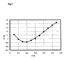
- the ( ⁇ d) was determined by comparing the equation (1) with the curve of the loss of the pressure of the main body versus time. Then, based on the resultant of the determined ( ⁇ d), the data regarding the resistance to the ventilation of a contaminated cloth ( ⁇ d) versus the ratio of the apertures of the pleats (P/H) were plotted on a graph. It is shown in FIG. 6 . It shows a curve (a regression curve) expressing the outline of these data.
- the specific ratio of the apertures of the pleats (P S /H S ) was defined as a reference by arbitrarily selecting it.
- the area for installing the main bodies of the pleated-type filters F that had the specific ratio of the apertures of the pleats (P S /H S ) was defined as (A S ), when they were installed in the apparatus for collecting dust, so that the filters were directed vertically, as in FIG. 1 .
- the resistance to the ventilation of the contaminated filtering cloth was defined as ( ⁇ d S ).
- the area for installing the main bodies of the pleated-type filters F that had the ratio of the apertures of the pleats (P/H) was defined as (A), and the resistance to the ventilation of the contaminated filtering cloth was defined as ( ⁇ d).
- the area of filtration can be (n) times smaller.
- the area (A) for installing the pleated-type filters is (m ⁇ n) times the area (A S ) for installing the pleated-type filters.
- the ratio of the apertures of the pleats (P/H), which is defined by the intervals (P) between the crests of adjacent pleats of the main body 2 and the heights (H) of its pleats, of the main body 2 of the pleated-type filter, range from 0.1 to 0.3. It is more preferable that the ratio of the apertures of the pleats (P/H) range from 0.15 to 0.25. The optimal value of it is 0.2.
- the amount of discharged air is less than the range of 1.3 ⁇ 1.5 (NL/m 2 )
- the performance for shaking off dust greatly decreases.
- the amount of discharged air is greater than the range
- the performance for shaking off dust is only slightly affected by the change of the amount of discharged air.
- the amount of discharged air increases, the cost of the operation increases.
- the result of the measurements is shown in FIG. 9 . From FIG. 9 , the following becomes clear. A large amount of secondary air is sucked into the main bodies 2 of the pleated-type filter based on the ejector effect caused by the compressed air that is blown into the main bodies 2 . Accordingly, the efficiency for shaking off the dust that accumulates in the main body 2 of the filter can be improved. As a result, it is preferable that the ratio (D/S) range from 0.3 to 0.6, since then the resistance to ventilation of a contaminated cloth ( ⁇ d) is minimized. It is more preferable that the ratio (D/S) range from 0.4 to 0.5.
- the curve of the resistance to ventilation of a contaminated cloth becomes flat. Namely, in this range the performance for shaking off the dust is not widely affected by the time of a pulse. Since the amount of the discharged air increases when the time of a pulse increases, the cost of the operation of the apparatus increases.
- the time of every pulse for jetting air range from 80 to 100 (msec). It is more preferable that the time of every pulse for jetting air be 100 (msec).
- the performance for shaking off the dust is not widely affected by the pressure of the compressed air. Since the amount of the discharged air increases when the pressure of the compressed air increases, the cost of the operation of the apparatus increases. Thus, it is preferable that the pressure of the compressed air range from 0.45 to 0.55 (MPa). It is more preferable that the pressure of the compressed air be 0.5 (MPa).
- the pressure of the compressed air range from 0.45 to 0.55 (MPa) and the time of a pulse for jetting air ranges from 80 to 100 (msec), and that it is more preferable that the time of a pulse for jetting air be 100 (msec).
- FIG. 1 shows an elevational and sectional view of the embodiment of the pleated-type filter of the present invention. It is used for the apparatus for collecting dust.
- FIG. 2 shows a side and sectional view of the pleated-type filter of FIG. 1 .
- FIG. 3 shows an elevational and sectional view of the main part of the apparatus for collecting dust.
- FIG. 4 shows the jet device for shaking off dust from filters of the apparatus for collecting dust.
- FIG. 5 is a schematic diagram showing the ratio of the apertures of the pleats (P/H).
- FIG. 6 is a graph showing the relationship between the ratio of the apertures of the pleats (P/H) of the main body of the pleated-type filter and the resistance to ventilation of a contaminated cloth ( ⁇ d).
- FIG. 7 is a graph showing a relationship between the ratio of the apertures of the pleats (P/H) of the main body of the pleated-type filter and the value of A/A S .
- FIG. 8 is a graph showing the relationship between the amount of discharged air per 1 m 2 of the area of the filtration of the main body of the pleated-type filter and the resistance to ventilation of a contaminated cloth ( ⁇ d).
- FIG. 9 is a graph showing the relationship between the ratio (D/S) and the resistance to ventilation of a contaminated cloth ( ⁇ d).
- the ratio (D/S) is defined by the diameter (D) of the upper opening of the main body of the pleated-type filter and the distance (S) between the upper surface of the pleated-type filter F and the jet port of the manifold of the jet device.
- FIG. 10 is a graph showing the relationship between the time of a pulse for jetting air and the resistance to ventilation of a contaminated cloth ( ⁇ d).
- FIG. 11 is a graph showing the relationship between the pressure of the compressed air used for jetting air and the resistance to ventilation of a contaminated cloth ( ⁇ d).
Landscapes
- Chemical & Material Sciences (AREA)
- Chemical Kinetics & Catalysis (AREA)
- Physics & Mathematics (AREA)
- Geometry (AREA)
- Filtering Of Dispersed Particles In Gases (AREA)
Abstract
Description
-
- Patent Document 1: Japanese Patent Publication Laid-open No. H07-16413
- Patent Document 2: Japanese Patent Publication Laid-open No. H08-309137
ΔP=(ζd+α×c×u×t)×μ×u (1)
-
- α is defined as a specific resistance to ventilation (m/kg) of a layer of dust. Namely, it is defined as a coefficient of a resistance to the ventilation of the layer of dust newly accumulated in the filter after the operation for shaking off dust is completed.
- c is defined as a concentration of dust (g/m3) that is determined based on the amount of the dust that has accumulated on the filtering cloth.
- u is defined as the rate of air (m/min) passing through a filtering cloth.
- t is time (min).
- μ is the viscosity of the air (Pa·s).
(P/H)=m(P S /H S) (2)
ζd=nζd S (3)
A/A S =m×n (4)
A/A S=(P/H×ζd)/(P S /H S ×ζd S) (5)
Claims (8)
Applications Claiming Priority (9)
| Application Number | Priority Date | Filing Date | Title |
|---|---|---|---|
| JP2006-200471 | 2006-07-24 | ||
| JP2006200471 | 2006-07-24 | ||
| JP2006226667 | 2006-08-23 | ||
| JP2006-226667 | 2006-08-23 | ||
| JP2006-229646 | 2006-08-25 | ||
| JP2006229646 | 2006-08-25 | ||
| JP2007056543A JP2008073683A (en) | 2006-07-24 | 2007-03-07 | Pleat-type filter for dust collector and dust collector |
| JP2007-056543 | 2007-03-07 | ||
| PCT/JP2007/063010 WO2008013024A1 (en) | 2006-07-24 | 2007-06-28 | Pleat type filter for dust collector and dust collector |
Publications (2)
| Publication Number | Publication Date |
|---|---|
| US20090183472A1 US20090183472A1 (en) | 2009-07-23 |
| US8062396B2 true US8062396B2 (en) | 2011-11-22 |
Family
ID=38981340
Family Applications (1)
| Application Number | Title | Priority Date | Filing Date |
|---|---|---|---|
| US12/374,979 Expired - Fee Related US8062396B2 (en) | 2006-07-24 | 2007-06-28 | Apparatus for collecting dust and a pleated-type filter therefor |
Country Status (3)
| Country | Link |
|---|---|
| US (1) | US8062396B2 (en) |
| JP (1) | JP2008073683A (en) |
| WO (1) | WO2008013024A1 (en) |
Cited By (1)
| Publication number | Priority date | Publication date | Assignee | Title |
|---|---|---|---|---|
| US20130055900A1 (en) * | 2010-03-19 | 2013-03-07 | Ralf Sauer | Vacuum Cleaner Filter Bag |
Families Citing this family (4)
| Publication number | Priority date | Publication date | Assignee | Title |
|---|---|---|---|---|
| NO345512B1 (en) * | 2019-02-22 | 2021-03-22 | Peakvent As | Method, device and system for air filtering and purifying |
| WO2020171718A1 (en) * | 2019-02-22 | 2020-08-27 | Peakvent As | Air filter device |
| US20220226764A1 (en) * | 2019-05-08 | 2022-07-21 | Donaldson Company, Inc. | Pulse air cleaner system with pulse tube extension |
| CN113813704B (en) * | 2021-09-16 | 2022-10-11 | 南昌大学 | Pleated filter cylinder device with air valve |
Citations (12)
| Publication number | Priority date | Publication date | Assignee | Title |
|---|---|---|---|---|
| JPS63319018A (en) | 1987-06-23 | 1988-12-27 | Amano Corp | Pulse jet type dust collecting filter |
| US4857192A (en) * | 1986-08-27 | 1989-08-15 | Nitto Electric Industrial Co., Ltd. | In phase corrugated plate membrane module support |
| JPH0716413A (en) | 1993-06-30 | 1995-01-20 | Osamu Asai | Dust collector having hollow filter |
| US5562746A (en) | 1994-04-11 | 1996-10-08 | Donaldson Company, Inc. | Air filter assembly for filtering air with particulate matter |
| JPH08309137A (en) | 1995-05-22 | 1996-11-26 | A M Shii:Kk | Cartridge filter element for dust collector |
| JPH10230121A (en) | 1997-02-17 | 1998-09-02 | Riyuuki Eng:Kk | Dust collector |
| JP2000042336A (en) | 1998-07-29 | 2000-02-15 | Kumakura Kogyo Kk | Cartridge filter |
| JP2001300237A (en) | 2000-04-28 | 2001-10-30 | Nippon Steel Corp | Method for collecting dust using bag filter type dust collector |
| US6517612B1 (en) * | 2001-10-29 | 2003-02-11 | Gore Enterprise Holdings, Inc. | Centrifugal filtration device |
| JP2004534646A (en) | 2001-07-12 | 2004-11-18 | ショイヒ ゲゼルシャフト ミット ベシュレンクテル ハフツング | Method and apparatus for dedusting a dust-containing waste gas filter |
| JP2005125179A (en) | 2003-10-22 | 2005-05-19 | Toray Fine Chemicals Co Ltd | Molded filter |
| US20080047430A1 (en) * | 2006-08-17 | 2008-02-28 | Japan Vilene Company, Ltd. | Filter element, method of manufacture and use |
Family Cites Families (2)
| Publication number | Priority date | Publication date | Assignee | Title |
|---|---|---|---|---|
| JP2652213B2 (en) * | 1988-08-31 | 1997-09-10 | 佐伯建設工業株式会社 | Super soft soil covering method |
| JP4110628B2 (en) * | 1997-09-11 | 2008-07-02 | 東レ株式会社 | Fabric and manufacturing method thereof |
-
2007
- 2007-03-07 JP JP2007056543A patent/JP2008073683A/en active Pending
- 2007-06-28 US US12/374,979 patent/US8062396B2/en not_active Expired - Fee Related
- 2007-06-28 WO PCT/JP2007/063010 patent/WO2008013024A1/en active Application Filing
Patent Citations (15)
| Publication number | Priority date | Publication date | Assignee | Title |
|---|---|---|---|---|
| US4857192A (en) * | 1986-08-27 | 1989-08-15 | Nitto Electric Industrial Co., Ltd. | In phase corrugated plate membrane module support |
| JPS63319018A (en) | 1987-06-23 | 1988-12-27 | Amano Corp | Pulse jet type dust collecting filter |
| JPH0716413A (en) | 1993-06-30 | 1995-01-20 | Osamu Asai | Dust collector having hollow filter |
| US5562746A (en) | 1994-04-11 | 1996-10-08 | Donaldson Company, Inc. | Air filter assembly for filtering air with particulate matter |
| JPH09511942A (en) | 1994-04-11 | 1997-12-02 | ドナルドソン・カンパニー・インコーポレーテッド | Air filter assembly for filtering air containing particles |
| JPH08309137A (en) | 1995-05-22 | 1996-11-26 | A M Shii:Kk | Cartridge filter element for dust collector |
| JPH10230121A (en) | 1997-02-17 | 1998-09-02 | Riyuuki Eng:Kk | Dust collector |
| JP2000042336A (en) | 1998-07-29 | 2000-02-15 | Kumakura Kogyo Kk | Cartridge filter |
| JP2001300237A (en) | 2000-04-28 | 2001-10-30 | Nippon Steel Corp | Method for collecting dust using bag filter type dust collector |
| JP2004534646A (en) | 2001-07-12 | 2004-11-18 | ショイヒ ゲゼルシャフト ミット ベシュレンクテル ハフツング | Method and apparatus for dedusting a dust-containing waste gas filter |
| US20040261375A1 (en) | 2001-07-12 | 2004-12-30 | Scheuch Gmbh | Method and device for cleaning filters for dust-laden waste gases |
| US6517612B1 (en) * | 2001-10-29 | 2003-02-11 | Gore Enterprise Holdings, Inc. | Centrifugal filtration device |
| JP2005507763A (en) | 2001-10-29 | 2005-03-24 | ゴア エンタープライズ ホールディングス,インコーポレイティド | Centrifugal filtration device |
| JP2005125179A (en) | 2003-10-22 | 2005-05-19 | Toray Fine Chemicals Co Ltd | Molded filter |
| US20080047430A1 (en) * | 2006-08-17 | 2008-02-28 | Japan Vilene Company, Ltd. | Filter element, method of manufacture and use |
Non-Patent Citations (1)
| Title |
|---|
| International Search Report, PCT/JP2007/063010. |
Cited By (4)
| Publication number | Priority date | Publication date | Assignee | Title |
|---|---|---|---|---|
| US20130055900A1 (en) * | 2010-03-19 | 2013-03-07 | Ralf Sauer | Vacuum Cleaner Filter Bag |
| US20130061566A1 (en) * | 2010-03-19 | 2013-03-14 | Ralf Sauer | Vacuum Cleaner Filter Bag |
| US10178932B2 (en) * | 2010-03-19 | 2019-01-15 | Eurofilters Holding N.V. | Vacuum cleaner filter bag |
| US10188248B2 (en) * | 2010-03-19 | 2019-01-29 | Eurofilters Holding N.V. | Vacuum cleaner filter bag |
Also Published As
| Publication number | Publication date |
|---|---|
| JP2008073683A (en) | 2008-04-03 |
| WO2008013024A1 (en) | 2008-01-31 |
| US20090183472A1 (en) | 2009-07-23 |
Similar Documents
| Publication | Publication Date | Title |
|---|---|---|
| US10898836B2 (en) | Filter with exterior and interior media components and method of filtering | |
| US8062396B2 (en) | Apparatus for collecting dust and a pleated-type filter therefor | |
| US3798878A (en) | Filter cleaning apparatus | |
| KR830001386B1 (en) | Bag filter with air diffuser combined with filter bag support | |
| JP7193868B2 (en) | Rectangular filter, assembly, and method for filtering | |
| AU2008203160B2 (en) | Airflow reducing and redirecting arrangement for industrial baghouse | |
| US20070241044A1 (en) | Fuel Filter | |
| US20200122073A1 (en) | Filter systems with dirty air chamber spacer elements and methods of using the same | |
| US9132370B2 (en) | Droplet precipitator | |
| US20140007771A1 (en) | Liquid drainage from coalescing filter medium with drainage channels | |
| KR101416563B1 (en) | Air purification equipment | |
| US7708794B2 (en) | Separator made of a fibrous porous material such as a felt | |
| US20110162336A1 (en) | Filter for Removing Particles from Gas Flows | |
| WO2023135080A1 (en) | Candle filter device | |
| WO2016083882A1 (en) | Filter element | |
| DK1838406T3 (en) | Folded air filter with opposite impulse air flow cleaning | |
| US20210060465A1 (en) | Retrofitting and use of rectangular filters, assembly and method for filtration | |
| SU1367843A3 (en) | Filtering device for cleaning air | |
| KR20190000650A (en) | Lower Cap for Dust Collector Filter and Cartridge Filer Having the Same | |
| JP6407130B2 (en) | Gas-liquid separation element for compressed gas and gas-liquid separation device | |
| TW202100223A (en) | Filter element | |
| JP4966884B2 (en) | Filtration water collecting device and gas discharge pipe | |
| KR101140129B1 (en) | Filter for compressed air | |
| US11752462B2 (en) | Effluent processing apparatus and method for a vehicle air brake charging system | |
| KR101947998B1 (en) | Carbon filter |
Legal Events
| Date | Code | Title | Description |
|---|---|---|---|
| AS | Assignment |
Owner name: SINTOKOGIO, LTD, JAPAN Free format text: ASSIGNMENT OF ASSIGNORS INTEREST;ASSIGNORS:AMANO, HIROYUKI;WATANABE, HIROAKI;IKENO, HIDENORI;AND OTHERS;REEL/FRAME:022159/0828 Effective date: 20090105 |
|
| FEPP | Fee payment procedure |
Free format text: PAYOR NUMBER ASSIGNED (ORIGINAL EVENT CODE: ASPN); ENTITY STATUS OF PATENT OWNER: LARGE ENTITY |
|
| STCF | Information on status: patent grant |
Free format text: PATENTED CASE |
|
| FPAY | Fee payment |
Year of fee payment: 4 |
|
| FEPP | Fee payment procedure |
Free format text: PAYOR NUMBER ASSIGNED (ORIGINAL EVENT CODE: ASPN); ENTITY STATUS OF PATENT OWNER: LARGE ENTITY Free format text: PAYER NUMBER DE-ASSIGNED (ORIGINAL EVENT CODE: RMPN); ENTITY STATUS OF PATENT OWNER: LARGE ENTITY |
|
| FEPP | Fee payment procedure |
Free format text: MAINTENANCE FEE REMINDER MAILED (ORIGINAL EVENT CODE: REM.); ENTITY STATUS OF PATENT OWNER: LARGE ENTITY |
|
| LAPS | Lapse for failure to pay maintenance fees |
Free format text: PATENT EXPIRED FOR FAILURE TO PAY MAINTENANCE FEES (ORIGINAL EVENT CODE: EXP.); ENTITY STATUS OF PATENT OWNER: LARGE ENTITY |
|
| STCH | Information on status: patent discontinuation |
Free format text: PATENT EXPIRED DUE TO NONPAYMENT OF MAINTENANCE FEES UNDER 37 CFR 1.362 |
|
| FP | Lapsed due to failure to pay maintenance fee |
Effective date: 20191122 |