US8066414B2 - LED lamp - Google Patents
LED lamp Download PDFInfo
- Publication number
- US8066414B2 US8066414B2 US12/199,472 US19947208A US8066414B2 US 8066414 B2 US8066414 B2 US 8066414B2 US 19947208 A US19947208 A US 19947208A US 8066414 B2 US8066414 B2 US 8066414B2
- Authority
- US
- United States
- Prior art keywords
- led lamp
- support
- lamp according
- retrofit led
- cover
- Prior art date
- Legal status (The legal status is an assumption and is not a legal conclusion. Google has not performed a legal analysis and makes no representation as to the accuracy of the status listed.)
- Active, expires
Links
Images


Classifications
-
- F—MECHANICAL ENGINEERING; LIGHTING; HEATING; WEAPONS; BLASTING
- F21—LIGHTING
- F21V—FUNCTIONAL FEATURES OR DETAILS OF LIGHTING DEVICES OR SYSTEMS THEREOF; STRUCTURAL COMBINATIONS OF LIGHTING DEVICES WITH OTHER ARTICLES, NOT OTHERWISE PROVIDED FOR
- F21V29/00—Protecting lighting devices from thermal damage; Cooling or heating arrangements specially adapted for lighting devices or systems
- F21V29/50—Cooling arrangements
- F21V29/70—Cooling arrangements characterised by passive heat-dissipating elements, e.g. heat-sinks
- F21V29/83—Cooling arrangements characterised by passive heat-dissipating elements, e.g. heat-sinks the elements having apertures, ducts or channels, e.g. heat radiation holes
-
- F—MECHANICAL ENGINEERING; LIGHTING; HEATING; WEAPONS; BLASTING
- F21—LIGHTING
- F21K—NON-ELECTRIC LIGHT SOURCES USING LUMINESCENCE; LIGHT SOURCES USING ELECTROCHEMILUMINESCENCE; LIGHT SOURCES USING CHARGES OF COMBUSTIBLE MATERIAL; LIGHT SOURCES USING SEMICONDUCTOR DEVICES AS LIGHT-GENERATING ELEMENTS; LIGHT SOURCES NOT OTHERWISE PROVIDED FOR
- F21K9/00—Light sources using semiconductor devices as light-generating elements, e.g. using light-emitting diodes [LED] or lasers
- F21K9/20—Light sources comprising attachment means
- F21K9/23—Retrofit light sources for lighting devices with a single fitting for each light source, e.g. for substitution of incandescent lamps with bayonet or threaded fittings
- F21K9/232—Retrofit light sources for lighting devices with a single fitting for each light source, e.g. for substitution of incandescent lamps with bayonet or threaded fittings specially adapted for generating an essentially omnidirectional light distribution, e.g. with a glass bulb
-
- F—MECHANICAL ENGINEERING; LIGHTING; HEATING; WEAPONS; BLASTING
- F21—LIGHTING
- F21V—FUNCTIONAL FEATURES OR DETAILS OF LIGHTING DEVICES OR SYSTEMS THEREOF; STRUCTURAL COMBINATIONS OF LIGHTING DEVICES WITH OTHER ARTICLES, NOT OTHERWISE PROVIDED FOR
- F21V29/00—Protecting lighting devices from thermal damage; Cooling or heating arrangements specially adapted for lighting devices or systems
- F21V29/50—Cooling arrangements
- F21V29/60—Cooling arrangements characterised by the use of a forced flow of gas, e.g. air
- F21V29/67—Cooling arrangements characterised by the use of a forced flow of gas, e.g. air characterised by the arrangement of fans
- F21V29/677—Cooling arrangements characterised by the use of a forced flow of gas, e.g. air characterised by the arrangement of fans the fans being used for discharging
-
- F—MECHANICAL ENGINEERING; LIGHTING; HEATING; WEAPONS; BLASTING
- F21—LIGHTING
- F21V—FUNCTIONAL FEATURES OR DETAILS OF LIGHTING DEVICES OR SYSTEMS THEREOF; STRUCTURAL COMBINATIONS OF LIGHTING DEVICES WITH OTHER ARTICLES, NOT OTHERWISE PROVIDED FOR
- F21V29/00—Protecting lighting devices from thermal damage; Cooling or heating arrangements specially adapted for lighting devices or systems
- F21V29/50—Cooling arrangements
- F21V29/70—Cooling arrangements characterised by passive heat-dissipating elements, e.g. heat-sinks
- F21V29/74—Cooling arrangements characterised by passive heat-dissipating elements, e.g. heat-sinks with fins or blades
- F21V29/75—Cooling arrangements characterised by passive heat-dissipating elements, e.g. heat-sinks with fins or blades with fins or blades having different shapes, thicknesses or spacing
-
- F—MECHANICAL ENGINEERING; LIGHTING; HEATING; WEAPONS; BLASTING
- F21—LIGHTING
- F21V—FUNCTIONAL FEATURES OR DETAILS OF LIGHTING DEVICES OR SYSTEMS THEREOF; STRUCTURAL COMBINATIONS OF LIGHTING DEVICES WITH OTHER ARTICLES, NOT OTHERWISE PROVIDED FOR
- F21V29/00—Protecting lighting devices from thermal damage; Cooling or heating arrangements specially adapted for lighting devices or systems
- F21V29/50—Cooling arrangements
- F21V29/70—Cooling arrangements characterised by passive heat-dissipating elements, e.g. heat-sinks
- F21V29/74—Cooling arrangements characterised by passive heat-dissipating elements, e.g. heat-sinks with fins or blades
- F21V29/76—Cooling arrangements characterised by passive heat-dissipating elements, e.g. heat-sinks with fins or blades with essentially identical parallel planar fins or blades, e.g. with comb-like cross-section
- F21V29/763—Cooling arrangements characterised by passive heat-dissipating elements, e.g. heat-sinks with fins or blades with essentially identical parallel planar fins or blades, e.g. with comb-like cross-section the planes containing the fins or blades having the direction of the light emitting axis
-
- F—MECHANICAL ENGINEERING; LIGHTING; HEATING; WEAPONS; BLASTING
- F21—LIGHTING
- F21V—FUNCTIONAL FEATURES OR DETAILS OF LIGHTING DEVICES OR SYSTEMS THEREOF; STRUCTURAL COMBINATIONS OF LIGHTING DEVICES WITH OTHER ARTICLES, NOT OTHERWISE PROVIDED FOR
- F21V29/00—Protecting lighting devices from thermal damage; Cooling or heating arrangements specially adapted for lighting devices or systems
- F21V29/50—Cooling arrangements
- F21V29/70—Cooling arrangements characterised by passive heat-dissipating elements, e.g. heat-sinks
- F21V29/74—Cooling arrangements characterised by passive heat-dissipating elements, e.g. heat-sinks with fins or blades
- F21V29/77—Cooling arrangements characterised by passive heat-dissipating elements, e.g. heat-sinks with fins or blades with essentially identical diverging planar fins or blades, e.g. with fan-like or star-like cross-section
- F21V29/777—Cooling arrangements characterised by passive heat-dissipating elements, e.g. heat-sinks with fins or blades with essentially identical diverging planar fins or blades, e.g. with fan-like or star-like cross-section the planes containing the fins or blades having directions perpendicular to the light emitting axis
-
- F—MECHANICAL ENGINEERING; LIGHTING; HEATING; WEAPONS; BLASTING
- F21—LIGHTING
- F21V—FUNCTIONAL FEATURES OR DETAILS OF LIGHTING DEVICES OR SYSTEMS THEREOF; STRUCTURAL COMBINATIONS OF LIGHTING DEVICES WITH OTHER ARTICLES, NOT OTHERWISE PROVIDED FOR
- F21V29/00—Protecting lighting devices from thermal damage; Cooling or heating arrangements specially adapted for lighting devices or systems
- F21V29/50—Cooling arrangements
- F21V29/502—Cooling arrangements characterised by the adaptation for cooling of specific components
- F21V29/506—Cooling arrangements characterised by the adaptation for cooling of specific components of globes, bowls or cover glasses
-
- F—MECHANICAL ENGINEERING; LIGHTING; HEATING; WEAPONS; BLASTING
- F21—LIGHTING
- F21V—FUNCTIONAL FEATURES OR DETAILS OF LIGHTING DEVICES OR SYSTEMS THEREOF; STRUCTURAL COMBINATIONS OF LIGHTING DEVICES WITH OTHER ARTICLES, NOT OTHERWISE PROVIDED FOR
- F21V3/00—Globes; Bowls; Cover glasses
- F21V3/02—Globes; Bowls; Cover glasses characterised by the shape
-
- F—MECHANICAL ENGINEERING; LIGHTING; HEATING; WEAPONS; BLASTING
- F21—LIGHTING
- F21Y—INDEXING SCHEME ASSOCIATED WITH SUBCLASSES F21K, F21L, F21S and F21V, RELATING TO THE FORM OR THE KIND OF THE LIGHT SOURCES OR OF THE COLOUR OF THE LIGHT EMITTED
- F21Y2107/00—Light sources with three-dimensionally disposed light-generating elements
- F21Y2107/30—Light sources with three-dimensionally disposed light-generating elements on the outer surface of cylindrical surfaces, e.g. rod-shaped supports having a circular or a polygonal cross section
-
- F—MECHANICAL ENGINEERING; LIGHTING; HEATING; WEAPONS; BLASTING
- F21—LIGHTING
- F21Y—INDEXING SCHEME ASSOCIATED WITH SUBCLASSES F21K, F21L, F21S and F21V, RELATING TO THE FORM OR THE KIND OF THE LIGHT SOURCES OR OF THE COLOUR OF THE LIGHT EMITTED
- F21Y2113/00—Combination of light sources
- F21Y2113/10—Combination of light sources of different colours
- F21Y2113/13—Combination of light sources of different colours comprising an assembly of point-like light sources
-
- F—MECHANICAL ENGINEERING; LIGHTING; HEATING; WEAPONS; BLASTING
- F21—LIGHTING
- F21Y—INDEXING SCHEME ASSOCIATED WITH SUBCLASSES F21K, F21L, F21S and F21V, RELATING TO THE FORM OR THE KIND OF THE LIGHT SOURCES OR OF THE COLOUR OF THE LIGHT EMITTED
- F21Y2115/00—Light-generating elements of semiconductor light sources
- F21Y2115/10—Light-emitting diodes [LED]
Definitions
- the increased desire for energy saving is accompanied by an increased demand to replace ordinary incandescent lamps, for example, of 40 W to 60 W, by energy-saving LED lamps, and preferably in a so-called retrofit, in which LED lamps can be used in ordinary systems with the most identical possible appearance.
- ordinary incandescent lamps for example, of 40 W to 60 W
- LED lamps can be used in ordinary systems with the most identical possible appearance.
- passive cooling cooling elements without forced convection by a fan
- Previous retrofit lamps operate with passive cooling and are therefore restricted to power dissipations of max 10 W.
- all cooling ribs may be arranged parallel to each other.
- the cooling ribs may be arranged angled to each other, especially with angular symmetry.
- several LEDs may be arranged uniformly or symmetrically on the surface of at least one hollow element.
- control electronics to control the at least one LED may be integrated in the lamp base.
- the at least one LED may have at least two LEDs of different color.
- the LED lamp may further comprise a signal receiver to receive signals to adjust color output.
- the LED lamp may further comprise a fan for active generation of an air stream through at least one of the hollow elements.
- FIG. 1 shows an LED lamp in a side view
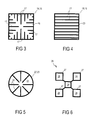
- FIG. 3 shows the support in a top view with cooling ribs according to a first embodiment
- FIG. 4 shows a support in a top view with cooling ribs according to a second embodiment
- FIG. 5 shows a support in a top view with cooling ribs according to a third embodiment
- the LED lamp may have a lamp base and at least one support connected to the lamp base, at least one LED being mounted on the support.
- the support also has at least one hollow element with at least two openings to permit air flow through a cavity of at least one hollow element.
- the support By forming the support as a hollow element with at least two openings, an air stream can be produced through the cavity of the cooling element during operation of the LED lamp, which cools the support and therefore the elements mounted on it. Consequently, lamps, especially retrofit LED lamps, can be provided with a higher power than 10 W in permanent operation even with passive cooling.
- a single-color (including white) LED can be used as LED, or several, especially different colored LEDs (including white).
- the support can be preferably designed, so that it stands perpendicular relative to the LED lamp, i.e., with its openings one above the other. Because of this, a chimney effect with increased air flow and therefore improved air cooling can be generated.
- the shape of the hollow element is not restricted to a specific shape or basic shape, as long as the shape permits air flow.
- An LED lamp in which the hollow element has a cylindrical basic shape, whose base surface and/or cover surface has at least one air passage opening, may be particularly preferred.
- an LED lamp in which the hollow element has the base shape of a parallelepiped, especially a cuboid, in which at least two opposite surfaces each have at least one air passage opening.
- openings can be present as an alternative or in addition at another site in the support, for example, in a side wall.
- the support need only have or form one hollow element. However, it can also be preferred if the support has or forms several hollow elements, for example, several cuboid and/or cylindrical hollow elements, especially when they are connected to each other by cooling ribs.
- At least one cooling rib especially a cooling fin, be arranged in at least one cavity.
- cooling ribs are arranged parallel to each other.
- cooling ribs are arranged angled to each other, especially angularly symmetric, for example, stellate in top view.
- LEDs especially all LEDs, may be preferably arranged uniformly (especially symmetrically) on the surface (especially outward-directed surface) of at least one hollow element. This achieves a situation, in which the LED lamp comes close in its emission characteristic to that of an incandescent lamp.
- An LED lamp may be preferred, in which control electronics to operate the at least one LED is integrated in the lamp base.
- control components can also or exclusively be mounted on the support.
- the LED has at least two LEDs of different color, especially for additive color mixing to white.
- LED clusters from the color combinations RGB, RGGB, RRGB, etc. are particularly advantageous.
- the control electronics can vary a pulse width control of the LEDs.
- the LED lamp preferably may have a signal receiver to receive corresponding control signals.
- the control signals can use radio infrared as medium, for example via a WLAN network (signal receiver is a WLAN receiver), via an SMS (signal receiver is a telephone-radio receiver, for example, a GSM receiver) and so forth.
- the LED lamp preferably may have a fan for active generation of an air stream through at least one hollow element.
- the fan preferably may sit on an air passage opening of a hollow element.
- An LED lamp having a control device for temperature-dependent control of fan power, may be also preferred.
- the LED lamp preferably also may have a cover to cover the support.
- the cover preferably may have a light-scattering property, has a base shape in the form/outline of a bulb of an ordinary incandescent lamp and/or has a phosphor, especially for wavelength conversion, for example, based on phosphorus.
- the cover preferably may have at least one air passage opening in the cover, especially an air outlet opening to blow out an air stream, especially in the upper area of the cover, but also, or in addition, an air inlet opening to draw in an air stream, especially in the lower area of the cover.
- the passage opening can also be provided on the lower end of the cover, so that blowing against the viewer is effectively prevented.
- the LED can also be flowed around from the outside.
- an LED lamp having at least one air passage opening in the lamp base may also be preferred, especially as an air inlet opening to draw in an air stream into the cavity of the at least one hollow element.
- FIG. 1 shows an LED lamp with a socket or a lamp base 2 , which includes a screw thread 3 , for example, according to E27 or E14.
- a support 4 on which several LEDs 5 are mounted and specifically in the peripheral direction, distributed as equally as possible on the outside, is electrically and mechanically connected to lamp base 2 .
- the support 4 is designed as a vertically standing hollow element, as further described in detail below.
- the support 4 has an air passage opening on the top and bottom (without figure) to permit an essentially vertical air stream through a cavity or internal space in it.
- the support 4 sits on a fan 6 , which covers the lower air passage opening. Air flow through support 4 is intensified by fan 6 .
- the support 4 and fan 6 are enclosed by a transparent cover 7 , which fits in a standardized outline for incandescent lamps, so that the user observes a trusted lamp shape, which increases product acceptance.
- air passage openings outward are provided in the LED lamp 1 .
- air intake openings (without figure) are provided laterally in base 2 and in the lower part of cover 7 , through which an incoming air stream 8 is produced from the outside into the LED lamp 1 or the intake side of fan 6 .
- the fan 6 blows the drawn-in cooling air 8 through the cavity of support 4 upward, in which the discharge stream 9 is released outward through a discharge channel 10 in cover 7 .
- the cover can be designed transparent or scattering, milky white and/or with a phosphor.
- LEDs 5 By the essentially uniform arrangement of LEDs 5 , a light characteristic close to an ordinary light bulb is produced.
- Primary optics for example, Argus lenses, can be used here.
- FIG. 2 shows the LED lamp from FIG. 1 as a simplified sectional view, for example, leaving out the cover.
- the cooling air 8 is guided through openings in the cover (without figure) and openings 11 in the base 2 to fan 6 and blown out through a cavity 12 of the support 4 upward as discharge stream 9 .
- Cooling fins 13 for reinforced cooling of the support 4 are arranged in cavity 12 .
- FIG. 3 shows in a top view a square support 14 (a cuboid support in three dimensions), which forms a hollow element 15 with a cavity 16 for passage of a cooling air stream.
- the support 14 and the cavity 15 enclose cooling fins 17 , which extend from the wall of support 14 into cavity 16 .
- the cooling fins 17 are formed from a well heat-conducting metal, copper or aluminum.
- the cooling fins 17 form four groups of straight and parallel cooling ribs with graded length, each of which start from a different side wall of support 14 .
- the center point of support 14 can correspond to a location on the longitudinal axis and the support 14 can extend accordingly along the longitudinal axis of the LED lamp, here perpendicular to the plane of the drawing.
- the LEDs (not shown) are mounted on the outside of the support 14 .
- the plate 17 can be connected to a metal core of the support 14 by heat-conducting contacts.
- FIG. 4 shows another variant of a support 18 in a view similar to FIG. 3 .
- the square-shaped support 18 has in a top view a cavity 20 with cooling fins 21 as individual hollow element 19 .
- the cooling fins 21 in contrast to FIG. 3 , however, are now all arranged parallel and extend from one side wall to the opposite side wall.
- FIG. 5 shows another variant of a support 22 in a view similar to FIG. 3 .
- the support 22 is now designed in a top view circular as a single hollow element 23 .
- the support 22 and hollow element 23 have in cavity 24 straight cooling fins 25 , which extend from the wall to the center in stellate fashion.
- the support 22 has a cylindrical basic shape or outside contour.
- This support 22 relative to the supports from FIG. 3 and FIG. 4 , has the advantage that LEDs can be arranged on the outside in the peripheral direction more uniformly distributed, for example, with radial symmetry.
Abstract
Description
- 1 LED lamp
- 2 Lamp base
- 3 Screw thread
- 4 Support
- 5 LED
- 6 Fan
- 7 Cover
- 8 Cooling air stream
- 9 Exhaust stream
- 10 Exhaust channel
- 11 Opening
- 12 Cavity
- 13 Cooling fin
- 14 Support
- 15 Hollow element
- 16 Cavity
- 17 Cooling fin
- 18 Support
- 19 Hollow element
- 20 Cavity
- 21 Cooling fin
- 22 Support
- 23 Hollow element
- 24 Cavity
- 25 Cooling fin
- 26 Support
- 27 Hollow element
- 28 Cavity
- L Longitudinal axis
Claims (20)
Applications Claiming Priority (3)
| Application Number | Priority Date | Filing Date | Title |
|---|---|---|---|
| DE102007040444A DE102007040444B8 (en) | 2007-08-28 | 2007-08-28 | Led lamp |
| DE102007040444 | 2007-08-28 | ||
| DE102007040444.3 | 2007-08-28 |
Publications (2)
| Publication Number | Publication Date |
|---|---|
| US20090059559A1 US20090059559A1 (en) | 2009-03-05 |
| US8066414B2 true US8066414B2 (en) | 2011-11-29 |
Family
ID=40298827
Family Applications (1)
| Application Number | Title | Priority Date | Filing Date |
|---|---|---|---|
| US12/199,472 Active 2028-10-18 US8066414B2 (en) | 2007-08-28 | 2008-08-27 | LED lamp |
Country Status (2)
| Country | Link |
|---|---|
| US (1) | US8066414B2 (en) |
| DE (1) | DE102007040444B8 (en) |
Cited By (26)
| Publication number | Priority date | Publication date | Assignee | Title |
|---|---|---|---|---|
| US20100289407A1 (en) * | 2009-05-12 | 2010-11-18 | Anderson Leroy E | Led room light |
| US20110089838A1 (en) * | 2009-10-20 | 2011-04-21 | Cree Led Lighting Solutions, Inc. | Heat sinks and lamp incorporating same |
| US20110090686A1 (en) * | 2009-10-20 | 2011-04-21 | Cree Led Lighting Solutions Inc. | Compact Heat Sinks and Solid State Lamp Incorporating Same |
| US20110089830A1 (en) * | 2009-10-20 | 2011-04-21 | Cree Led Lighting Solutions, Inc. | Heat sinks and lamp incorporating same |
| US20110170288A1 (en) * | 2010-01-11 | 2011-07-14 | Led Folio Corporation | Led retrofit unit having adjustable heads for street lighting |
| US20110199005A1 (en) * | 2010-02-17 | 2011-08-18 | Eric Bretschneider | Lighting unit having lighting strips with light emitting elements and a remote luminescent material |
| US20120086340A1 (en) * | 2010-10-08 | 2012-04-12 | Kenjiro Hashizume | Air-cooling illumination apparatus |
| US8164237B2 (en) * | 2010-07-29 | 2012-04-24 | GEM-SUN Technologies Co., Ltd. | LED lamp with flow guide function |
| US20120147600A1 (en) * | 2008-09-08 | 2012-06-14 | Intematix Corporation | Light emitting diode (led) lamps |
| US20120268936A1 (en) * | 2011-04-19 | 2012-10-25 | Cree, Inc. | Heat sink structures, lighting elements and lamps incorporating same, and methods of making same |
| US20130175915A1 (en) * | 2012-01-09 | 2013-07-11 | Tai-Her Yang | Electric luminous body having heat dissipater with axial and radial air aperture |
| US8616714B2 (en) | 2011-10-06 | 2013-12-31 | Intematix Corporation | Solid-state lamps with improved radial emission and thermal performance |
| US8710721B1 (en) * | 2012-12-12 | 2014-04-29 | Genesis Photonics Inc. | Light emitting device |
| US20140247606A1 (en) * | 2011-11-25 | 2014-09-04 | Sengled Optoelectronics Co., Ltd | Led lighting device including heat dissipation structure and method for making the same |
| US8992051B2 (en) | 2011-10-06 | 2015-03-31 | Intematix Corporation | Solid-state lamps with improved radial emission and thermal performance |
| US20160290571A1 (en) * | 2015-03-30 | 2016-10-06 | Linmore Led Labs, Inc. | Heat dissipating led light bar |
| US9470391B2 (en) | 2011-11-17 | 2016-10-18 | Osram Gmbh | LED light source module |
| US9605840B1 (en) | 2016-05-23 | 2017-03-28 | Green Inova Lighting Technology (Shenzhen) Limited | LED kit |
| US20170284648A1 (en) * | 2016-04-04 | 2017-10-05 | Shoichi Nakamura | Led illumination device |
| US10378749B2 (en) | 2012-02-10 | 2019-08-13 | Ideal Industries Lighting Llc | Lighting device comprising shield element, and shield element |
| US10415787B2 (en) * | 2018-01-11 | 2019-09-17 | Osram Sylvania Inc. | Vehicle LED lamp having recirculating air channels |
| US10948135B2 (en) | 2013-10-28 | 2021-03-16 | Next Lighting Corp. | Linear lighting apparatus |
| IT201900022209A1 (en) | 2019-11-26 | 2021-05-26 | Osram Gmbh | Lamp and corresponding procedure |
| US20210262651A1 (en) * | 2018-07-13 | 2021-08-26 | 10644137 Canada Inc. | High-performance high-power led lighting systems and methods thereof |
| US20230272903A1 (en) * | 2020-07-28 | 2023-08-31 | Lumileds Llc | Lighting device for mounting to an optical element and method of manufacture |
| US11959625B2 (en) * | 2019-07-15 | 2024-04-16 | 10644137 Canada Inc. | High-performance high-power LED lighting systems and methods thereof |
Families Citing this family (87)
| Publication number | Priority date | Publication date | Assignee | Title |
|---|---|---|---|---|
| US8807789B2 (en) * | 2009-10-16 | 2014-08-19 | Dialight Corporation | LED illumination device for projecting light downward and to the side |
| US8118447B2 (en) | 2007-12-20 | 2012-02-21 | Altair Engineering, Inc. | LED lighting apparatus with swivel connection |
| US8680754B2 (en) | 2008-01-15 | 2014-03-25 | Philip Premysler | Omnidirectional LED light bulb |
| US8360599B2 (en) | 2008-05-23 | 2013-01-29 | Ilumisys, Inc. | Electric shock resistant L.E.D. based light |
| US8324817B2 (en) | 2008-10-24 | 2012-12-04 | Ilumisys, Inc. | Light and light sensor |
| US8901823B2 (en) | 2008-10-24 | 2014-12-02 | Ilumisys, Inc. | Light and light sensor |
| US7938562B2 (en) | 2008-10-24 | 2011-05-10 | Altair Engineering, Inc. | Lighting including integral communication apparatus |
| US8653984B2 (en) | 2008-10-24 | 2014-02-18 | Ilumisys, Inc. | Integration of LED lighting control with emergency notification systems |
| US8214084B2 (en) | 2008-10-24 | 2012-07-03 | Ilumisys, Inc. | Integration of LED lighting with building controls |
| US20100187961A1 (en) * | 2009-01-27 | 2010-07-29 | Keith Scott | Phosphor housing for light emitting diode lamp |
| DE102009011350A1 (en) * | 2009-03-05 | 2010-09-09 | Osram Gesellschaft mit beschränkter Haftung | Lighting device with at least one heat sink |
| DE102009019227A1 (en) * | 2009-04-28 | 2011-01-13 | Ledon Lighting Jennersdorf Gmbh | LED lamp |
| EP2251584A1 (en) * | 2009-05-15 | 2010-11-17 | Koninklijke Philips Electronics N.V. | Electric lamp |
| US8941300B2 (en) | 2009-05-15 | 2015-01-27 | Koninklijke Philips N.V. | Electric lamp |
| US8186852B2 (en) | 2009-06-24 | 2012-05-29 | Elumigen Llc | Opto-thermal solution for multi-utility solid state lighting device using conic section geometries |
| DE202009015012U1 (en) | 2009-11-04 | 2010-01-07 | Hess Ag Form + Licht | LED lighting unit |
| US8466611B2 (en) * | 2009-12-14 | 2013-06-18 | Cree, Inc. | Lighting device with shaped remote phosphor |
| US9057511B2 (en) | 2010-03-03 | 2015-06-16 | Cree, Inc. | High efficiency solid state lamp and bulb |
| US20110227102A1 (en) * | 2010-03-03 | 2011-09-22 | Cree, Inc. | High efficacy led lamp with remote phosphor and diffuser configuration |
| US8632196B2 (en) * | 2010-03-03 | 2014-01-21 | Cree, Inc. | LED lamp incorporating remote phosphor and diffuser with heat dissipation features |
| US9275979B2 (en) * | 2010-03-03 | 2016-03-01 | Cree, Inc. | Enhanced color rendering index emitter through phosphor separation |
| US9310030B2 (en) * | 2010-03-03 | 2016-04-12 | Cree, Inc. | Non-uniform diffuser to scatter light into uniform emission pattern |
| US8931933B2 (en) * | 2010-03-03 | 2015-01-13 | Cree, Inc. | LED lamp with active cooling element |
| US9024517B2 (en) * | 2010-03-03 | 2015-05-05 | Cree, Inc. | LED lamp with remote phosphor and diffuser configuration utilizing red emitters |
| US10359151B2 (en) * | 2010-03-03 | 2019-07-23 | Ideal Industries Lighting Llc | Solid state lamp with thermal spreading elements and light directing optics |
| US9062830B2 (en) * | 2010-03-03 | 2015-06-23 | Cree, Inc. | High efficiency solid state lamp and bulb |
| US8562161B2 (en) * | 2010-03-03 | 2013-10-22 | Cree, Inc. | LED based pedestal-type lighting structure |
| US8882284B2 (en) | 2010-03-03 | 2014-11-11 | Cree, Inc. | LED lamp or bulb with remote phosphor and diffuser configuration with enhanced scattering properties |
| US9316361B2 (en) | 2010-03-03 | 2016-04-19 | Cree, Inc. | LED lamp with remote phosphor and diffuser configuration |
| US9625105B2 (en) * | 2010-03-03 | 2017-04-18 | Cree, Inc. | LED lamp with active cooling element |
| US9500325B2 (en) * | 2010-03-03 | 2016-11-22 | Cree, Inc. | LED lamp incorporating remote phosphor with heat dissipation features |
| WO2011119958A1 (en) | 2010-03-26 | 2011-09-29 | Altair Engineering, Inc. | Inside-out led bulb |
| EP2553320A4 (en) | 2010-03-26 | 2014-06-18 | Ilumisys Inc | Led light with thermoelectric generator |
| DE102010013310B4 (en) | 2010-03-29 | 2012-02-23 | Panasonic Electric Works Vossloh-Schwabe Gmbh | Operating circuit for operating a fan for a light module |
| DE102010013427B4 (en) * | 2010-03-30 | 2016-02-25 | Uv-Technik Speziallampen Gmbh | Lamp with openings in the base and gap between enveloping element and base |
| TWI408311B (en) * | 2010-05-25 | 2013-09-11 | Sunonwealth Electr Mach Ind Co | Lamp and heat sink thereof |
| US8201983B2 (en) * | 2010-06-01 | 2012-06-19 | Young Lighting Technology Inc. | Illuminating device |
| DE102010026335A1 (en) * | 2010-07-07 | 2012-01-12 | Star Right Limited | LED lamp for outdoor application, has control unit electrically connected to LED and with cooling fan that is attached to dissipative element, enabling cooling fan to allow airflow upwards and enabling LED to light up using delay circuit |
| US10451251B2 (en) | 2010-08-02 | 2019-10-22 | Ideal Industries Lighting, LLC | Solid state lamp with light directing optics and diffuser |
| US8523394B2 (en) | 2010-10-29 | 2013-09-03 | Ilumisys, Inc. | Mechanisms for reducing risk of shock during installation of light tube |
| US8487518B2 (en) * | 2010-12-06 | 2013-07-16 | 3M Innovative Properties Company | Solid state light with optical guide and integrated thermal guide |
| TWI457518B (en) * | 2010-12-13 | 2014-10-21 | Sunonwealth Electr Mach Ind Co | Lamp |
| BR112013016150A2 (en) | 2010-12-30 | 2018-07-10 | Elumigen Llc | lighting assembly that has adjacent light sources and light tubes. |
| US20120194054A1 (en) * | 2011-02-02 | 2012-08-02 | 3M Innovative Properties Company | Solid state light with optical diffuser and integrated thermal guide |
| US9234655B2 (en) | 2011-02-07 | 2016-01-12 | Cree, Inc. | Lamp with remote LED light source and heat dissipating elements |
| US9068701B2 (en) | 2012-01-26 | 2015-06-30 | Cree, Inc. | Lamp structure with remote LED light source |
| US11251164B2 (en) | 2011-02-16 | 2022-02-15 | Creeled, Inc. | Multi-layer conversion material for down conversion in solid state lighting |
| JP5475732B2 (en) * | 2011-02-21 | 2014-04-16 | 株式会社東芝 | Lighting device |
| DE102011007221B4 (en) * | 2011-04-12 | 2022-05-19 | Ledvance Gmbh | lighting device |
| CN102207252B (en) * | 2011-04-14 | 2013-03-20 | 厦门阳光恩耐照明有限公司 | LED bulb |
| CN103782088B (en) | 2011-06-09 | 2015-11-25 | 伊路米根有限责任公司 | Use the solid luminous device of the passage of heat in the housing |
| US8777463B2 (en) | 2011-06-23 | 2014-07-15 | Cree, Inc. | Hybrid solid state emitter printed circuit board for use in a solid state directional lamp |
| USD696436S1 (en) | 2011-06-23 | 2013-12-24 | Cree, Inc. | Solid state directional lamp |
| US8777455B2 (en) * | 2011-06-23 | 2014-07-15 | Cree, Inc. | Retroreflective, multi-element design for a solid state directional lamp |
| US9072171B2 (en) | 2011-08-24 | 2015-06-30 | Ilumisys, Inc. | Circuit board mount for LED light |
| US8746929B2 (en) | 2011-10-14 | 2014-06-10 | GE Lighting Solutions, LLC | Device with combined features of lighting and air purification |
| CN102494257A (en) * | 2011-12-30 | 2012-06-13 | 上海顿格电子贸易有限公司 | Wide-angle light-emitting diode (LED) ball bubble lamp capable of radiating heat by internal and external natural convection of air |
| US9184518B2 (en) | 2012-03-02 | 2015-11-10 | Ilumisys, Inc. | Electrical connector header for an LED-based light |
| US9488359B2 (en) | 2012-03-26 | 2016-11-08 | Cree, Inc. | Passive phase change radiators for LED lamps and fixtures |
| US9188322B2 (en) * | 2012-03-26 | 2015-11-17 | Asia Vital Components Co., Ltd. | Heat dissipation structure for LED lighting |
| DE102012205469A1 (en) * | 2012-04-03 | 2013-10-10 | Osram Gmbh | LIGHTING DEVICE AND METHOD FOR OPERATING AN ILLUMINATOR |
| FR2990590B1 (en) * | 2012-05-10 | 2017-08-04 | Sylvain Duclos | ELECTRIC BULB, WITH LIGHT-EMITTING DIODES, IN PARTICULAR OF HEADLAMP OF A MOTOR VEHICLE |
| WO2014008463A1 (en) | 2012-07-06 | 2014-01-09 | Ilumisys, Inc. | Power supply assembly for led-based light tube |
| US9271367B2 (en) | 2012-07-09 | 2016-02-23 | Ilumisys, Inc. | System and method for controlling operation of an LED-based light |
| US9097412B1 (en) | 2012-11-21 | 2015-08-04 | Robert M. Pinato | LED lightbulb having a heat sink with a plurality of thermal mounts each having two LED element to emit an even light distribution |
| CN202955537U (en) * | 2012-12-04 | 2013-05-29 | 上海三思电子工程有限公司 | LED (Light-Emitting Diode) bulb lamp capable of realizing wide-angle luminescence |
| US9285084B2 (en) | 2013-03-14 | 2016-03-15 | Ilumisys, Inc. | Diffusers for LED-based lights |
| US9328908B2 (en) * | 2013-04-16 | 2016-05-03 | Checkers Industrial Products, Llc | LED strobe light with integrated magnet and heat sink chimney |
| US8894252B2 (en) * | 2013-04-19 | 2014-11-25 | Technical Consumer Products, Inc. | Filament LED lamp |
| US9267650B2 (en) | 2013-10-09 | 2016-02-23 | Ilumisys, Inc. | Lens for an LED-based light |
| US20150103535A1 (en) * | 2013-10-14 | 2015-04-16 | Wen-Sung Hu | Air-Cooled and Moisture-Resistant LED Lamp and Bulb |
| WO2015112437A1 (en) | 2014-01-22 | 2015-07-30 | Ilumisys, Inc. | Led-based light with addressed leds |
| CN105940263B (en) * | 2014-01-29 | 2020-05-29 | 飞利浦照明控股有限公司 | LED bulb |
| US9360188B2 (en) | 2014-02-20 | 2016-06-07 | Cree, Inc. | Remote phosphor element filled with transparent material and method for forming multisection optical elements |
| JP6041158B2 (en) * | 2014-02-28 | 2016-12-07 | 岩崎電気株式会社 | LED lamp |
| JP5975303B2 (en) * | 2014-02-28 | 2016-08-23 | 岩崎電気株式会社 | LED lamp and heat sink used therefor |
| US9510400B2 (en) | 2014-05-13 | 2016-11-29 | Ilumisys, Inc. | User input systems for an LED-based light |
| US9651219B2 (en) | 2014-08-20 | 2017-05-16 | Elumigen Llc | Light bulb assembly having internal redirection element for improved directional light distribution |
| GB2551452B (en) | 2014-09-28 | 2018-06-20 | Zhejiang Super Lighting Electric Appliance Co Ltd | LED lamp bulb |
| JP3203081U (en) * | 2015-02-04 | 2016-03-10 | 嘉▲興▼山蒲照明▲電▼器有限公司Jiaxing Super Lighting Electric Appliance Co.,Ltd | Light bulb shaped LED lamp |
| USD755414S1 (en) | 2015-02-12 | 2016-05-03 | Tadd, LLC | LED lamp |
| USD755415S1 (en) | 2015-03-03 | 2016-05-03 | Tadd, LLC | LED lamp |
| CZ2015226A3 (en) * | 2015-03-31 | 2016-08-03 | Varroc Lighting Systems, s.r.o. | Light source cooler |
| US10161568B2 (en) | 2015-06-01 | 2018-12-25 | Ilumisys, Inc. | LED-based light with canted outer walls |
| WO2017218108A1 (en) * | 2016-06-15 | 2017-12-21 | Roca Richard | Improved led heating lamp and fan |
| US10066801B1 (en) * | 2017-10-04 | 2018-09-04 | Osram Sylvania Inc. | Vehicle lamp reflector having ventilation channel adjacent lamp capsule |
| WO2019127515A1 (en) * | 2017-12-29 | 2019-07-04 | 深圳市超频三科技股份有限公司 | Lamp and light source substrate |
Citations (18)
| Publication number | Priority date | Publication date | Assignee | Title |
|---|---|---|---|---|
| US20020176250A1 (en) * | 2001-05-26 | 2002-11-28 | Gelcore, Llc | High power led power pack for spot module illumination |
| US20040109318A1 (en) * | 2002-07-03 | 2004-06-10 | Nash Derek J. | Reflector assembly for automated luminaires |
| US6787999B2 (en) * | 2002-10-03 | 2004-09-07 | Gelcore, Llc | LED-based modular lamp |
| JP2004296245A (en) | 2003-03-26 | 2004-10-21 | Matsushita Electric Works Ltd | Led lamp |
| US6864513B2 (en) * | 2003-05-07 | 2005-03-08 | Kaylu Industrial Corporation | Light emitting diode bulb having high heat dissipating efficiency |
| US20050111234A1 (en) * | 2003-11-26 | 2005-05-26 | Lumileds Lighting U.S., Llc | LED lamp heat sink |
| US7144140B2 (en) * | 2005-02-25 | 2006-12-05 | Tsung-Ting Sun | Heat dissipating apparatus for lighting utility |
| DE202007002751U1 (en) | 2007-02-24 | 2007-04-26 | Chen, Bor-Jang, Pyng-Jenn City | Cooling device for lamp has several cooling fins inside base, holes through floor of base and heat-exchange tubes on switching plate |
| EP1047903B1 (en) | 1998-09-17 | 2007-06-27 | Koninklijke Philips Electronics N.V. | Led lamp |
| US20070201232A1 (en) * | 2006-02-27 | 2007-08-30 | Kuei-Fang Chen | Illumination apparatus having heat dissipating capability |
| US20070230184A1 (en) * | 2006-03-31 | 2007-10-04 | Shuy Geoffrey W | Heat exchange enhancement |
| US20070291473A1 (en) * | 2002-03-28 | 2007-12-20 | Neil Traynor | Methods and apparatus relating to improved visual recognition and safety |
| US20080007954A1 (en) * | 2006-07-05 | 2008-01-10 | Jia-Hao Li | Heat-Dissipating Structure For LED Lamp |
| US7476002B2 (en) * | 2003-07-02 | 2009-01-13 | S.C. Johnson & Son, Inc. | Color changing light devices with active ingredient and sound emission for mood enhancement |
| US20090021944A1 (en) * | 2007-07-18 | 2009-01-22 | Fu Zhun Precision Industry (Shen Zhen) Co., Ltd. | Led lamp |
| US7524089B2 (en) * | 2004-02-06 | 2009-04-28 | Daejin Dmp Co., Ltd. | LED light |
| US7607802B2 (en) * | 2007-07-23 | 2009-10-27 | Tamkang University | LED lamp instantly dissipating heat as effected by multiple-layer substrates |
| US7637628B2 (en) * | 2006-06-13 | 2009-12-29 | Light-Pod, Inc. | LED light pod with modular optics and heat dissipation structure |
-
2007
- 2007-08-28 DE DE102007040444A patent/DE102007040444B8/en not_active Expired - Fee Related
-
2008
- 2008-08-27 US US12/199,472 patent/US8066414B2/en active Active
Patent Citations (18)
| Publication number | Priority date | Publication date | Assignee | Title |
|---|---|---|---|---|
| EP1047903B1 (en) | 1998-09-17 | 2007-06-27 | Koninklijke Philips Electronics N.V. | Led lamp |
| US20020176250A1 (en) * | 2001-05-26 | 2002-11-28 | Gelcore, Llc | High power led power pack for spot module illumination |
| US20070291473A1 (en) * | 2002-03-28 | 2007-12-20 | Neil Traynor | Methods and apparatus relating to improved visual recognition and safety |
| US20040109318A1 (en) * | 2002-07-03 | 2004-06-10 | Nash Derek J. | Reflector assembly for automated luminaires |
| US6787999B2 (en) * | 2002-10-03 | 2004-09-07 | Gelcore, Llc | LED-based modular lamp |
| JP2004296245A (en) | 2003-03-26 | 2004-10-21 | Matsushita Electric Works Ltd | Led lamp |
| US6864513B2 (en) * | 2003-05-07 | 2005-03-08 | Kaylu Industrial Corporation | Light emitting diode bulb having high heat dissipating efficiency |
| US7476002B2 (en) * | 2003-07-02 | 2009-01-13 | S.C. Johnson & Son, Inc. | Color changing light devices with active ingredient and sound emission for mood enhancement |
| US20050111234A1 (en) * | 2003-11-26 | 2005-05-26 | Lumileds Lighting U.S., Llc | LED lamp heat sink |
| US7524089B2 (en) * | 2004-02-06 | 2009-04-28 | Daejin Dmp Co., Ltd. | LED light |
| US7144140B2 (en) * | 2005-02-25 | 2006-12-05 | Tsung-Ting Sun | Heat dissipating apparatus for lighting utility |
| US20070201232A1 (en) * | 2006-02-27 | 2007-08-30 | Kuei-Fang Chen | Illumination apparatus having heat dissipating capability |
| US20070230184A1 (en) * | 2006-03-31 | 2007-10-04 | Shuy Geoffrey W | Heat exchange enhancement |
| US7637628B2 (en) * | 2006-06-13 | 2009-12-29 | Light-Pod, Inc. | LED light pod with modular optics and heat dissipation structure |
| US20080007954A1 (en) * | 2006-07-05 | 2008-01-10 | Jia-Hao Li | Heat-Dissipating Structure For LED Lamp |
| DE202007002751U1 (en) | 2007-02-24 | 2007-04-26 | Chen, Bor-Jang, Pyng-Jenn City | Cooling device for lamp has several cooling fins inside base, holes through floor of base and heat-exchange tubes on switching plate |
| US20090021944A1 (en) * | 2007-07-18 | 2009-01-22 | Fu Zhun Precision Industry (Shen Zhen) Co., Ltd. | Led lamp |
| US7607802B2 (en) * | 2007-07-23 | 2009-10-27 | Tamkang University | LED lamp instantly dissipating heat as effected by multiple-layer substrates |
Non-Patent Citations (3)
| Title |
|---|
| English language abstract for JP 2004296245 A. |
| English Translation of Yakoya JP 2004-296245. * |
| German Office Action dated Jul. 13, 2010. |
Cited By (42)
| Publication number | Priority date | Publication date | Assignee | Title |
|---|---|---|---|---|
| US20120147600A1 (en) * | 2008-09-08 | 2012-06-14 | Intematix Corporation | Light emitting diode (led) lamps |
| US8952613B2 (en) * | 2009-05-12 | 2015-02-10 | Leroy E. Anderson | LED room light |
| US20100289407A1 (en) * | 2009-05-12 | 2010-11-18 | Anderson Leroy E | Led room light |
| US20110089838A1 (en) * | 2009-10-20 | 2011-04-21 | Cree Led Lighting Solutions, Inc. | Heat sinks and lamp incorporating same |
| US20110090686A1 (en) * | 2009-10-20 | 2011-04-21 | Cree Led Lighting Solutions Inc. | Compact Heat Sinks and Solid State Lamp Incorporating Same |
| US20110089830A1 (en) * | 2009-10-20 | 2011-04-21 | Cree Led Lighting Solutions, Inc. | Heat sinks and lamp incorporating same |
| US9030120B2 (en) | 2009-10-20 | 2015-05-12 | Cree, Inc. | Heat sinks and lamp incorporating same |
| US9217542B2 (en) | 2009-10-20 | 2015-12-22 | Cree, Inc. | Heat sinks and lamp incorporating same |
| US9243758B2 (en) | 2009-10-20 | 2016-01-26 | Cree, Inc. | Compact heat sinks and solid state lamp incorporating same |
| US20110170288A1 (en) * | 2010-01-11 | 2011-07-14 | Led Folio Corporation | Led retrofit unit having adjustable heads for street lighting |
| US8360607B2 (en) | 2010-02-17 | 2013-01-29 | Next Lighting Corp. | Lighting unit with heat-dissipating chimney |
| US8491165B2 (en) | 2010-02-17 | 2013-07-23 | Next Lighting Corp. | Lighting unit having lighting strips with light emitting elements and a remote luminescent material |
| US20110199769A1 (en) * | 2010-02-17 | 2011-08-18 | Eric Bretschneider | Lighting unit with heat-dissipating chimney |
| US8684566B2 (en) | 2010-02-17 | 2014-04-01 | Next Lighting, Corp. | Lighting unit with indirect light source |
| US20110199005A1 (en) * | 2010-02-17 | 2011-08-18 | Eric Bretschneider | Lighting unit having lighting strips with light emitting elements and a remote luminescent material |
| US8164237B2 (en) * | 2010-07-29 | 2012-04-24 | GEM-SUN Technologies Co., Ltd. | LED lamp with flow guide function |
| US20120086340A1 (en) * | 2010-10-08 | 2012-04-12 | Kenjiro Hashizume | Air-cooling illumination apparatus |
| US20120268936A1 (en) * | 2011-04-19 | 2012-10-25 | Cree, Inc. | Heat sink structures, lighting elements and lamps incorporating same, and methods of making same |
| US10030863B2 (en) * | 2011-04-19 | 2018-07-24 | Cree, Inc. | Heat sink structures, lighting elements and lamps incorporating same, and methods of making same |
| US8992051B2 (en) | 2011-10-06 | 2015-03-31 | Intematix Corporation | Solid-state lamps with improved radial emission and thermal performance |
| US8616714B2 (en) | 2011-10-06 | 2013-12-31 | Intematix Corporation | Solid-state lamps with improved radial emission and thermal performance |
| US9470391B2 (en) | 2011-11-17 | 2016-10-18 | Osram Gmbh | LED light source module |
| US9194572B2 (en) * | 2011-11-25 | 2015-11-24 | Sengled Optoelectronics Co., Ltd | LED lighting device including heat dissipation structure and method for making the same |
| US20140247606A1 (en) * | 2011-11-25 | 2014-09-04 | Sengled Optoelectronics Co., Ltd | Led lighting device including heat dissipation structure and method for making the same |
| US20130175915A1 (en) * | 2012-01-09 | 2013-07-11 | Tai-Her Yang | Electric luminous body having heat dissipater with axial and radial air aperture |
| US9500356B2 (en) * | 2012-01-09 | 2016-11-22 | Tai-Her Yang | Heat dissipater with axial and radial air aperture and application device thereof |
| US10378749B2 (en) | 2012-02-10 | 2019-08-13 | Ideal Industries Lighting Llc | Lighting device comprising shield element, and shield element |
| US8710721B1 (en) * | 2012-12-12 | 2014-04-29 | Genesis Photonics Inc. | Light emitting device |
| US11767951B2 (en) | 2013-10-28 | 2023-09-26 | Satco Products, Inc. | Linear lamp replacement |
| US10948135B2 (en) | 2013-10-28 | 2021-03-16 | Next Lighting Corp. | Linear lighting apparatus |
| US20160290571A1 (en) * | 2015-03-30 | 2016-10-06 | Linmore Led Labs, Inc. | Heat dissipating led light bar |
| US10054296B2 (en) * | 2015-03-30 | 2018-08-21 | Linmore Led Labs, Inc. | Heat dissipating LED light bar |
| US10174927B2 (en) * | 2016-04-04 | 2019-01-08 | Shoichi Nakamura | LED illumination device with heat sink having a portion of heat fins exposed to axial forced flow from a cooling fan |
| US20170284648A1 (en) * | 2016-04-04 | 2017-10-05 | Shoichi Nakamura | Led illumination device |
| US10018345B2 (en) | 2016-05-23 | 2018-07-10 | Green Inova Lighting Technology (Shenzhen) Limited | LED kit |
| US9605840B1 (en) | 2016-05-23 | 2017-03-28 | Green Inova Lighting Technology (Shenzhen) Limited | LED kit |
| US10415787B2 (en) * | 2018-01-11 | 2019-09-17 | Osram Sylvania Inc. | Vehicle LED lamp having recirculating air channels |
| US20210262651A1 (en) * | 2018-07-13 | 2021-08-26 | 10644137 Canada Inc. | High-performance high-power led lighting systems and methods thereof |
| US11959625B2 (en) * | 2019-07-15 | 2024-04-16 | 10644137 Canada Inc. | High-performance high-power LED lighting systems and methods thereof |
| IT201900022209A1 (en) | 2019-11-26 | 2021-05-26 | Osram Gmbh | Lamp and corresponding procedure |
| EP3828463A1 (en) | 2019-11-26 | 2021-06-02 | OSRAM GmbH | Lamp and corresponding method |
| US20230272903A1 (en) * | 2020-07-28 | 2023-08-31 | Lumileds Llc | Lighting device for mounting to an optical element and method of manufacture |
Also Published As
| Publication number | Publication date |
|---|---|
| DE102007040444B8 (en) | 2013-10-17 |
| US20090059559A1 (en) | 2009-03-05 |
| DE102007040444B4 (en) | 2013-03-07 |
| DE102007040444A1 (en) | 2009-03-05 |
Similar Documents
| Publication | Publication Date | Title |
|---|---|---|
| US8066414B2 (en) | LED lamp | |
| KR101659505B1 (en) | Electric lamp | |
| US8616714B2 (en) | Solid-state lamps with improved radial emission and thermal performance | |
| US9933148B2 (en) | LED light bulbs | |
| US9500356B2 (en) | Heat dissipater with axial and radial air aperture and application device thereof | |
| CN102341649B (en) | With the lighting device of at least one radiator | |
| US8992051B2 (en) | Solid-state lamps with improved radial emission and thermal performance | |
| JP5968911B2 (en) | Lighting device | |
| CN105940259B (en) | LED bulb | |
| US20130294068A1 (en) | Lamp with light emitting elements surrounding active cooling device | |
| KR101645154B1 (en) | Led lighting apparatus for tunnel | |
| US20130135868A1 (en) | Lighting device | |
| JP2011009210A (en) | Illumination device | |
| US20130176723A1 (en) | Solid-state lamps with improved radial emission and thermal performance | |
| EP2868966B1 (en) | A bulb with LEDs | |
| WO2013052749A2 (en) | Solid-state lamps with improved radial emission and thermal performance | |
| US20190063738A1 (en) | Led bulb | |
| CN113946083A (en) | Lighting device | |
| WO2014102642A1 (en) | Lighting assembly | |
| TWM457842U (en) | Illumination device | |
| CN103080647A (en) | Led lighting device cooled by a fan and a heat dissipating unit with arc-shaped fins | |
| TW201432196A (en) | Illumination device |
Legal Events
| Date | Code | Title | Description |
|---|---|---|---|
| AS | Assignment |
Owner name: OSRAM GESELLSCHAFT MIT BESCHRAENKTER HAFTUNG, GERM Free format text: ASSIGNMENT OF ASSIGNORS INTEREST;ASSIGNORS:PABST, WOLFGANG;STRAUSS, STEFFEN;REEL/FRAME:021560/0399;SIGNING DATES FROM 20080717 TO 20080721 Owner name: OSRAM GESELLSCHAFT MIT BESCHRAENKTER HAFTUNG, GERM Free format text: ASSIGNMENT OF ASSIGNORS INTEREST;ASSIGNORS:PABST, WOLFGANG;STRAUSS, STEFFEN;SIGNING DATES FROM 20080717 TO 20080721;REEL/FRAME:021560/0399 |
|
| STCF | Information on status: patent grant |
Free format text: PATENTED CASE |
|
| FEPP | Fee payment procedure |
Free format text: PAYOR NUMBER ASSIGNED (ORIGINAL EVENT CODE: ASPN); ENTITY STATUS OF PATENT OWNER: LARGE ENTITY |
|
| FPAY | Fee payment |
Year of fee payment: 4 |
|
| MAFP | Maintenance fee payment |
Free format text: PAYMENT OF MAINTENANCE FEE, 8TH YEAR, LARGE ENTITY (ORIGINAL EVENT CODE: M1552); ENTITY STATUS OF PATENT OWNER: LARGE ENTITY Year of fee payment: 8 |
|
| AS | Assignment |
Owner name: OSRAM AG, GERMANY Free format text: CHANGE OF NAME;ASSIGNOR:OSRAM GESELLSCHAFT MIT BESCHRAENKTER HAFTUNG;REEL/FRAME:053144/0163 Effective date: 20110719 Owner name: LEDVANCE GMBH, GERMANY Free format text: ASSIGNMENT OF ASSIGNORS INTEREST;ASSIGNOR:OSRAM GMBH;REEL/FRAME:053144/0291 Effective date: 20170207 Owner name: OSRAM GMBH, GERMANY Free format text: CHANGE OF NAME;ASSIGNOR:OSRAM AG;REEL/FRAME:053259/0743 Effective date: 20121025 |
|
| MAFP | Maintenance fee payment |
Free format text: PAYMENT OF MAINTENANCE FEE, 12TH YEAR, LARGE ENTITY (ORIGINAL EVENT CODE: M1553); ENTITY STATUS OF PATENT OWNER: LARGE ENTITY Year of fee payment: 12 |