US8070409B2 - Method and apparatus for transporting steel billets - Google Patents
Method and apparatus for transporting steel billets Download PDFInfo
- Publication number
- US8070409B2 US8070409B2 US12/258,484 US25848408A US8070409B2 US 8070409 B2 US8070409 B2 US 8070409B2 US 25848408 A US25848408 A US 25848408A US 8070409 B2 US8070409 B2 US 8070409B2
- Authority
- US
- United States
- Prior art keywords
- flexible member
- workpieces
- engaging member
- secondary flexible
- hanger
- Prior art date
- Legal status (The legal status is an assumption and is not a legal conclusion. Google has not performed a legal analysis and makes no representation as to the accuracy of the status listed.)
- Active, expires
Links
Images


Classifications
-
- B—PERFORMING OPERATIONS; TRANSPORTING
- B65—CONVEYING; PACKING; STORING; HANDLING THIN OR FILAMENTARY MATERIAL
- B65G—TRANSPORT OR STORAGE DEVICES, e.g. CONVEYORS FOR LOADING OR TIPPING, SHOP CONVEYOR SYSTEMS OR PNEUMATIC TUBE CONVEYORS
- B65G47/00—Article or material-handling devices associated with conveyors; Methods employing such devices
- B65G47/74—Feeding, transfer, or discharging devices of particular kinds or types
- B65G47/90—Devices for picking-up and depositing articles or materials
- B65G47/92—Devices for picking-up and depositing articles or materials incorporating electrostatic or magnetic grippers
Definitions
- the present invention relates to transporting metal objects and more particularly to a method and apparatus for transporting steel billets from a randomly oriented condition in a staging area to a conveying system for further processing of the billets.
- Metal billets and other elongated metal objects can be used for a wide range of manufacturing processes. This requires that these billets be moved or transported through the manufacturing processes from when they are formed to when they are processed to produce other products. As can be appreciated, movement of these billets, or elongated objects, from a storage area to a processing phase of a facility can be accomplished by many means. As with other manufacturing processes, robots can be used for the transportation of objects.
- U.S. Pat. No. 3,587,872 discloses a mechanical arm and control means therefor that can be used to pick and place objects wherein this patent is incorporated by reference herein as background material showing same.
- Billets and other elongated objects have been used in manufacturing for many years wherein these objects must be moved or transported from one process to the next, stored, removed from storage and even manipulated or orientated for certain operations between the creation of the billet and the final processing of the billet.
- many methods have been used to transport or move these objects which include manual movement, vibratory feeders, conveyors, bins and pushers. These devices can be utilized to move or transport the billets from a first position to a second position.
- the location and orientation of the billet must be known before the billet can be moved from the first position to a second or known position. Further, interengagement with a desired number of billets at the first position, when the billet is in a randomly oriented condition, requires either manual manipulation by an operator or the use of sensors or other vision-type features on the movement device to properly orient the device. In this respect, and with respect to traditional jaws or grippers utilized in pick and place style manipulators, the device must know the orientation of the billet to properly align the jaws of the movement device with respect to the billet such that the jaws can grasp the billet. Once the billet is grasped, it can be manipulated as is needed for the particular operation.
- the movement device need to sense the position of the billet, it also must be able to articulate the jaws to properly orient the jaws relative to the billet to grasp the billet.
- this articulation can require multi-axis equipment so that the jaws can be oriented relative to the billet.
- the need for both vision and multi-axis articulation can greatly increase the costs of the device and can also greatly reduce the reliability and longevity of the device. This is especially true in the harsh environment typically associated with billet processing
- a system to feed an elongated metallic workpiece to a manufacturing process includes an automatically orienting gripping mechanism to interengage with a randomly oriented elongated object, such as a metallic billet, and a movement device that transports the object to a subsequent processing point such as to a conveying system that can be used to feed subsequent operations.
- a system to feed elongated metallic workpieces to a manufacturing process wherein the elongated workpieces have a workpiece body extending along a workpiece axis between a first workpiece end and a second workpiece end.
- the system includes a storage hopper configured to hold a plurality of the workpieces that are randomly oriented and a movement device.
- the movement device includes a frame and a workpiece support joined to the frame wherein the workpiece support is moveable between a load position proximate the hopper and an unload position away from the load position.
- This workpiece support further includes an engaging surface and a flexible extension joining the engaging surface to the frame thereby allowing the engaging surface to move relative to the frame and a means for selectively producing an attractive force between the engaging surface and a workpiece to direct the engaging surface to a desired number of the workpieces regardless of the position of the workpieces when the engaging surface is in the load position.
- the attractive force means can selectively secure the desired number of workpieces relative to the engaging surface in the load position and release it in the unload position.
- the system can further include a self-alignment apparatus to generally align the workpiece axis of the desired workpiece relative to the conveyor axis near the unload position.
- the system can include a conveyor at the unload position wherein the conveyor has a first conveyor end and a second conveyor end with a drive line moving along a driveline axis from the first conveyor end to the second conveyor end such that the second conveyor end directs the workpieces into a process and the unload position is over the conveyor.
- the system can be configured to secure a single workpiece and in another embodiment two workpieces.
- the movement device can be a robotic arm.
- the movement device can be a linear actuator.
- the manufacturing process is an induction heating process.
- the self-alignment feature is a pair of angled baffles positioned on either side of the drive line at the unload position.
- the pair of angled baffles is adjustable transverse to the conveyor axis to accommodate different size workpieces.
- the attractive force includes magnetic.
- the attractive force includes a vacuum.
- FIG. 1A is a elevated layout view of a manufacturing operation including an embodiment of a system for transporting elongated objects according to the present invention wherein the system is shown in a load position;
- FIG. 1B is the elevated layout view of FIG. 1A wherein the system is shown in an unload position;
- FIG. 2 is a perspective view of the movement device as is shown in FIG. 1 ;
- FIG. 3 is an enlarged perspective view of a workpiece support including multiple engaging components
- FIG. 3A is a sectional view taken along lines 3 A- 3 A in FIG. 3 ;
- FIG. 4 is an enlarged perspective view of a workpiece support including a single engaging component
- FIG. 4A is a sectional view taken along lines 4 A- 4 A in FIG. 4 ;
- FIG. 5 is a perspective view of another embodiment of the present which includes an orientation device at least partially spaced from the unload position shown in FIG. 1B ;
- FIG. 6 is an enlarged perspective view of a workpiece support according to another aspect of the present invention which includes powered rotation;
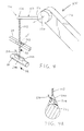
- FIG. 7 is a partially sectioned elevational view showing a workpiece support in relation to a conveying system above the unload position
- FIG. 8 is a partially sectioned elevational view showing the workpiece support in relation to a conveying system in the unload position
- FIG. 9 is a sectional view taken generally along lines 9 - 9 ;
- FIG. 10 is partially sectioned elevational view showing the workpiece support in relation to a conveying system in the unload position showing a workpiece having a different cross sectional configuration.
- FIGS. 1A and 1B show a manufacturing operation or system 10 that includes a storage hopper 20 and a manufacturing process 30 with a conveying system 40 capable of feeding a workpiece W into manufacturing process 30 .
- the manufacturing process can be a wide range of manufacturing processes including, but not limited to, a heating process to heat workpiece W.
- This heating process can be an induction heater and workpiece W can be a metal billet.
- the invention of this application should not be limited to the induction heating of metal billets.
- Manufacturing operation 10 further includes a movement device 50 configured to feed workpiece W to conveying system 40 .
- movement device 50 is configured to move a workpiece between a load position 60 ( FIG. 1A ) and an unload position 62 ( FIG. 1B ).
- the movement device can be any one of a number of motion devices including, but not limited to, pick and place devices, robotic arms, linear drives, and/or rotational drives configured to move a workpiece support 70 to position 60 such that the workpiece support can engage one or more workpieces W in hopper 20 , to remove the workpiece from hopper 20 and to move the workpiece towards position 62 wherein the workpiece can be deposited on conveying system 40 .
- the workpieces in hopper 20 can be controllably moved from the hopper to the conveyor such that workpiece W can be conveyed into a manufacturing operation.
- manufacturing operation 30 can be any one of a number of operations or multiple operations including an induction heating operation used to heat a metal billet for further processing in the manufacturing facility. Since the invention of this application has been found to work particularly well in connection with metal billets and induction heating, it is being described herein in connection with this application. However, as can be appreciated, the invention of this application is broader in its application.
- Hopper 20 can be any storage device used in manufacturing or other applications including a reusable containers and/or a disposable container 72 .
- storage hopper 20 can be a fixed hopper positioned on a surface such as the floor or a moving hopper wherein the storage hopper is, for example, rolled into position on a separate conveyor system, not shown.
- either style storage hopper can include the use of a disposable cardboard container mounted to a packing skid 74 such that a forklift can position a full hopper and remove an empty hopper as is needed.
- the hopper can include a tilting feature 76 to at least partially tilt the hopper for aiding in the positioning of the workpieces in the hopper when, for example, only a few workpieces are remaining in the hopper.
- the size and configuration of the storage hopper can vary greatly depending on the size of the workpiece and the production rate of the facility. As will be discussed in greater detail below, these differing sizes and configurations can impact the configuration of the workpiece support.
- movement device 50 is configured to move the workpiece support between load position 60 and unload position 62 such that the workpieces can be controllably transported from a storage condition to a processing condition regardless of the orientation of the workpiece in the hopper.
- Holder 70 accomplishes this by being configured to controllably secure and release one or more workpieces and; further, to engage a desired number of the workpieces for each cycle of the system from the load to the unload position automatically. Yet even further, this automatic engagement of the desired number of workpieces is achieved without manual manipulation, vision, sensors or powered actuation relative to the movement device. This allows movement device 50 to be a simple and reliable device and further simplifies the corresponding control or operating system such that costs are reduced and, repeatability and reliability are increased.
- movement device 50 is a multi-axis robot having a support pedestal 100 with rotating base 102 secured to pedestal 100 .
- Device 50 further includes a first arm 104 joined to base 102 by a first pivot connector 106 .
- Device 50 can further include a second arm 110 pivotally joined to arm 104 at a second pivot joint 112 .
- second arm 110 By including second arm 110 , the range and mobility of device 50 can be increased. Further, second arm 110 helps allow workpiece holder 70 to enter into hopper 20 .
- Workpiece holder 70 is joined to arm 110 and can also be joined by a pivoting or articulating joint such as a workpiece joint 120 . By including joint 120 , the range of motion of holder 70 is further increased.
- the movement device is controlled by an operating system 130 that controls the desired movement of the movement device.
- operating system 130 can also be configured to operate one or more other devices in system 10 .
- Operating system 130 can be any operating system known in the art including, but not limited to, a computer operating system.
- holder 70 includes a workpiece arm 150 joined at a first end 152 to joint 120 such that arm 150 extends to a distal end 154 .
- Arm 150 can be a rigid member as is shown in at least one embodiment of this application. However, is will be discussed in greater detail below, arm 150 also can be a flexible member.
- a workpiece support configuration 70 B wherein the workpiece support includes a quick change hanger arrangement 160 that can be used to quickly reconfigure system 10 according to the parameters of the manufacturing operation.
- hanger 160 can be used in combination with quick change lock blocks 168 to change the number of engagement members, the spacing between the members, the length of the members etc. which can be modified based on the hopper configuration and/or the workpiece configuration which will also be discussed in greater detail below.
- Hanger 160 and lock blocks 168 can use any quick change technology known in the art without detracting from the invention of this application.
- Workpiece holder 70 B is configured to engage two workpieces.
- Hanger 160 is joined to arm 150 by a flexible member 162 which can be used to increase the range of motion of the workpiece holder.
- Flexible members 164 and 166 extend between blocks 168 and the respective engagement members 174 and 176 wherein the length of members 164 and 166 can also be used to control the range of motion of holder 70 B.
- Engagement members 174 and 176 further include attraction and support devices 180 and 182 wherein members are spaced such that holder 70 B is configured to engage a single workpiece.
- engagement devices 180 and 182 can include a wide range of technologies used to locate and support (attract) randomly oriented workpieces. This includes permanent magnets, electro-magnets and other magnetic technologies, a vacuum, or any other method of attracting another object.
- Engagement devices 180 , 182 in this embodiment are electro-magnets positioned at or near engagement surfaces 184 and 186 , respectively, wherein these magnets are joined to operating system 130 by leads 170 and 172 which control when the electro-magnets are on and/or off. Since members 174 and 176 magnetically engage metal workpiece W, the members selectively secure themselves to the workpieces automatically based on attractive forces alone along with the movement device moving the holder within range of the workpieces.
- spacing D 1 between flexible members 164 and 166 and length D 2 of flexible members 164 and 166 can be configured such that each engagement device is not capable of engaging the same elongated object.
- spacing D 1 and length D 2 is based on the configuration and size of the workpiece.
- components 180 and 182 can be permanent magnets wherein these magnets are joined to a linear actuator such that they move relative to surfaces 184 and 186 , respectively. As these permanent magnets move away from engagement surfaces, the magnets loose their effect and the members are then in the “off” condition. Conversely, when the permanent magnets are in a position proximate to the corresponding engagement surface, the member is in the “on” condition. As with the other embodiments in this application, the permanent magnets can also be controlled by operating system 130 .
- some or all of the remaining components can be made from non-magnetizable materials to help prevent unwanted magnetization of these other components thereby preventing unwanted attractive forces.
- engagement devices 174 and 176 can automatically locate a respective billet without the need for sensors and/or vision components in movement device 50 .
- the size of storage hopper 20 will, at least in part, dictate the amount of motion that is necessary to allow engagement devices 174 and 176 to find a workpiece within the hopper.
- tilting device 76 can be used in connection with hopper 20 to minimize the range of motion necessary to direct the engagement members to the workpieces within the hopper. For example, larger hoppers could necessitate the need for longer flexible devices.
- the engagement devices can be simply lowered into the hopper and then automatically engage a workpiece from a randomly oriented pile of workpieces.
- movement device 50 can include a simple sensor in communication with operating system 130 to let the operating system know that a workpiece has been engaged and secured.
- workpiece support 70 C is shown.
- This embodiment includes hanger 160 and lock blocks 168 to allow for quick changeovers.
- workpiece W is shown which is an elongated member having a circular cross-sectional configuration.
- engagement member 200 includes a shaped engaging surface 202 configured to matingly engage with the outer cylindrical surface of workpiece W.
- workpiece support 70 C includes flexible member 162 and can further include a flexible member 163 configured to allow engagement member 200 to adequately move within the storage hopper to engage a workpiece. This particular configuration is designed to engage a single workpiece. However, more than one engagement member 200 could be mounted to hanger 160 without detracting from the invention of this application.
- engagement member 200 can includes a centrally located magnet 208 proximate to surface 202 to magnetically engage the workpiece when in load position 60 .
- magnet 208 can be an electro-magnet connected to operating system 130 by way of electrical connection 210 or an actuated permanent magnet, vacuum or any other attractive force technology.
- conveyor system 40 can include angled baffles 250 and 252 that are spaced from one another on either side of conveyor belt 254 .
- This conveyor system can be any known conveyor system and, therefore, it will not be discussed in greater detail in this application.
- Angled baffles 250 and 252 can be joined to conveyor 40 by way of adjustable brackets 260 wherein brackets 260 can include elongated slot 262 which can be used in connection with a fastener 264 to modify spacing S between the baffles based on the size of workpiece W.
- baffles 250 and 252 in combination with flexible members 162 , 164 and 166 , align workpiece W such that it is generally parallel to edges 270 and 272 of belt 254 when it reaches the belt.
- baffles 250 and 252 can be powered baffles connected to a linear actuation device (not shown) to allow quick adjustments to be made to spacing S. This powered system can also be connected to operating system 130 .
- workpiece holder 70 D is shown. This embodiment does not include a hanger assembly. Conversely holder 70 D includes a single engagement member 200 connected to a flexible member 222 which is joined directly to workpiece joint 120 .
- This embodiments can function similar to those discussed above; however, it further a rotational device 230 that can further help orient the workpiece holder and/or the workpiece during any point of the process.
- rotational device 230 can be either a powered rotational device and/or a freely rotating device which can be used to help orientation. Yet even further, rotational device 230 can include a locked and an unlocked condition. Again, these features will be discussed in greater detail below.
- rotational device 230 can be in an unlocked condition to allow the full and free movement of the engagement device relative to the movement device to help the alignment between the engagement member and the workpiece. Then, the rotational device can be mechanically moved to a set position to properly orient the workpiece relative to the conveyor belt before it reaches the conveyor.
- This arrangement is best suited for the workpiece support that includes a shaped engagement surface as is shown in FIG. 6 .
- the alignment or baffle structure can be spaced from the unload position.
- an alignment shoot 300 that can be positioned between load position 60 and unload position 62 and can include multiple alignment surfaces such as surfaces 302 , 304 and 306 .
- alignment device 300 As workpiece W is moved through alignment device 300 by the motion produced by movement device 50 , one or more of the surfaces of workpiece W engage one or more surfaces 302 , 304 and 306 which then begin to orient the workpiece relative to these known surfaces. This can be done in combination with selectively rotatable rotation device 230 or the other flexible members discussed above to align the workpiece.
- rotational device 230 can be unlocked to allow the free rotation of the workpiece relative to the alignment device. Then, once the workpiece is aligned, rotational device 230 can be locked. In addition, the flexibility of the flexible members could also be locked in yet another embodiment. As a result of this alignment feature, the orientation of the workpiece relative to the movement device would be known after the workpiece passes through the orientation device such that it can be positioned on the conveyor system without further orientation.
- rotational device 230 can provide, at least in part, the free rotational movement necessary to help align the workpiece with the conveying system as the workpiece engages baffles 250 and 252 .
- angle baffles 250 and 252 are adjusted based on the size and shape of workpiece W 2 wherein the square cross-sectional configuration of workpiece W 2 can be properly oriented to the conveyor.
- the strength of the magnet used in connection with any one of the work holders can be configured to only support a single billet which can also be used to ensure that only the desired number of workpieces is engaged by the workpiece holder in the load position.
Abstract
Description
Claims (28)
Priority Applications (1)
| Application Number | Priority Date | Filing Date | Title |
|---|---|---|---|
| US12/258,484 US8070409B2 (en) | 2007-11-05 | 2008-10-27 | Method and apparatus for transporting steel billets |
Applications Claiming Priority (2)
| Application Number | Priority Date | Filing Date | Title |
|---|---|---|---|
| US98543407P | 2007-11-05 | 2007-11-05 | |
| US12/258,484 US8070409B2 (en) | 2007-11-05 | 2008-10-27 | Method and apparatus for transporting steel billets |
Publications (2)
| Publication Number | Publication Date |
|---|---|
| US20090116940A1 US20090116940A1 (en) | 2009-05-07 |
| US8070409B2 true US8070409B2 (en) | 2011-12-06 |
Family
ID=40588235
Family Applications (1)
| Application Number | Title | Priority Date | Filing Date |
|---|---|---|---|
| US12/258,484 Active 2030-04-22 US8070409B2 (en) | 2007-11-05 | 2008-10-27 | Method and apparatus for transporting steel billets |
Country Status (1)
| Country | Link |
|---|---|
| US (1) | US8070409B2 (en) |
Cited By (2)
| Publication number | Priority date | Publication date | Assignee | Title |
|---|---|---|---|---|
| DE102019203435A1 (en) * | 2019-03-13 | 2020-09-17 | Volkswagen Aktiengesellschaft | Method for removing components arranged in layers in a transport container and device for carrying out the method |
| US20200407923A1 (en) * | 2019-06-27 | 2020-12-31 | B & B Metals, Inc. | Tie plate separator and method |
Families Citing this family (7)
| Publication number | Priority date | Publication date | Assignee | Title |
|---|---|---|---|---|
| US7717255B2 (en) * | 2006-10-27 | 2010-05-18 | Pearson Packaging Systems | End of arm tool, apparatus, and method of engaging an article |
| JP2011230239A (en) * | 2010-04-28 | 2011-11-17 | Honda Motor Co Ltd | Workpiece holding method |
| JP5837065B2 (en) * | 2011-06-29 | 2015-12-24 | 三菱電機株式会社 | Parts supply device |
| DE102012013030A1 (en) * | 2012-06-29 | 2014-04-24 | Liebherr-Verzahntechnik Gmbh | Device for the automatic removal of workpieces arranged in a container |
| DE102012013022A1 (en) * | 2012-06-29 | 2014-04-24 | Liebherr-Verzahntechnik Gmbh | Device for the automated handling of workpieces |
| CN105752683B (en) * | 2016-04-27 | 2018-03-16 | 福建师范大学福清分校 | A kind of the automatic of flow line tray picks up dress system |
| US11014226B2 (en) * | 2018-10-26 | 2021-05-25 | Toyota Motor Engineering & Manufacturing North America, Inc. | Automated pick and place apparatuses with object alignment systems |
Citations (22)
| Publication number | Priority date | Publication date | Assignee | Title |
|---|---|---|---|---|
| US3587872A (en) | 1969-04-28 | 1971-06-28 | Paul E Pauly | Mechanical arm and control means therefor |
| US3881605A (en) * | 1973-06-29 | 1975-05-06 | Ibm | Object orienting device to assist robot manipulator |
| US3926316A (en) * | 1975-02-14 | 1975-12-16 | Argil W Luttrell | Mobile sit-on toy crane |
| US3934920A (en) * | 1974-07-08 | 1976-01-27 | The Lodge & Shipley Company | Carriage for lifting and spreading rows of articles |
| US4266905A (en) * | 1979-04-20 | 1981-05-12 | Board Of Regents For Education Of The State Of Rhode Island | Apparatus for acquiring workpieces from a storage bin or the like |
| US4283165A (en) | 1978-09-04 | 1981-08-11 | Commissariat A L'energie Atomique | Motorized manipulator of the cable transmission type having an increased field of action |
| US4473247A (en) * | 1981-02-13 | 1984-09-25 | Matsushita Electric Industrial Co., Ltd. | Component mounting apparatus |
| US4482289A (en) * | 1980-09-11 | 1984-11-13 | Fujitsu Fanuc Limited | Robot hand of an industrial robot |
| US4501522A (en) | 1981-10-26 | 1985-02-26 | United Kingdom Atomic Energy Authority | Manipulator |
| US4539695A (en) * | 1984-01-06 | 1985-09-03 | The Perkin-Elmer Corporation | X-Ray lithography system |
| US4664434A (en) * | 1985-10-29 | 1987-05-12 | Harsco Corporation | Grouping head hoist |
| US4698775A (en) | 1985-05-17 | 1987-10-06 | Flexible Manufacturing Systems, Inc. | Self-contained mobile reprogrammable automation device |
| US4739872A (en) * | 1987-03-05 | 1988-04-26 | Amsted Industries Incorporated | Automated parts handling apparatus |
| US4806066A (en) | 1982-11-01 | 1989-02-21 | Microbot, Inc. | Robotic arm |
| JPH04283089A (en) * | 1991-03-06 | 1992-10-08 | Nippon Electric Glass Co Ltd | Handling method for plateform substance |
| US5207465A (en) * | 1991-10-24 | 1993-05-04 | Rich Donald S | Self-realigning vacuum pickup arrangement |
| US5261265A (en) * | 1992-06-22 | 1993-11-16 | Rwc, Inc. | Compliance apparatus and methods for gripping and transporting workpiece sheets such as appliance door blanks to be formed to and from a properly aligned forming position at a work station |
| US5308221A (en) * | 1990-08-02 | 1994-05-03 | Toyoda Koki Kabushiki Kaisha | Method and apparatus for controlling a robot having a floating hand |
| US6015174A (en) * | 1998-06-04 | 2000-01-18 | Eastman Kodak Company | Universal end effector for robotic applications |
| US6139078A (en) * | 1998-11-13 | 2000-10-31 | International Business Machines Corporation | Self-aligning end effector for small components |
| US6626630B1 (en) | 2002-06-24 | 2003-09-30 | Bakery Holdings Llc | Cartesian robot |
| US20060157476A1 (en) | 2003-01-24 | 2006-07-20 | Sintef Energiforskning As | Apparatus and a method for induction heating of pieces of electrically conducting and non-magnetic material |
-
2008
- 2008-10-27 US US12/258,484 patent/US8070409B2/en active Active
Patent Citations (22)
| Publication number | Priority date | Publication date | Assignee | Title |
|---|---|---|---|---|
| US3587872A (en) | 1969-04-28 | 1971-06-28 | Paul E Pauly | Mechanical arm and control means therefor |
| US3881605A (en) * | 1973-06-29 | 1975-05-06 | Ibm | Object orienting device to assist robot manipulator |
| US3934920A (en) * | 1974-07-08 | 1976-01-27 | The Lodge & Shipley Company | Carriage for lifting and spreading rows of articles |
| US3926316A (en) * | 1975-02-14 | 1975-12-16 | Argil W Luttrell | Mobile sit-on toy crane |
| US4283165A (en) | 1978-09-04 | 1981-08-11 | Commissariat A L'energie Atomique | Motorized manipulator of the cable transmission type having an increased field of action |
| US4266905A (en) * | 1979-04-20 | 1981-05-12 | Board Of Regents For Education Of The State Of Rhode Island | Apparatus for acquiring workpieces from a storage bin or the like |
| US4482289A (en) * | 1980-09-11 | 1984-11-13 | Fujitsu Fanuc Limited | Robot hand of an industrial robot |
| US4473247A (en) * | 1981-02-13 | 1984-09-25 | Matsushita Electric Industrial Co., Ltd. | Component mounting apparatus |
| US4501522A (en) | 1981-10-26 | 1985-02-26 | United Kingdom Atomic Energy Authority | Manipulator |
| US4806066A (en) | 1982-11-01 | 1989-02-21 | Microbot, Inc. | Robotic arm |
| US4539695A (en) * | 1984-01-06 | 1985-09-03 | The Perkin-Elmer Corporation | X-Ray lithography system |
| US4698775A (en) | 1985-05-17 | 1987-10-06 | Flexible Manufacturing Systems, Inc. | Self-contained mobile reprogrammable automation device |
| US4664434A (en) * | 1985-10-29 | 1987-05-12 | Harsco Corporation | Grouping head hoist |
| US4739872A (en) * | 1987-03-05 | 1988-04-26 | Amsted Industries Incorporated | Automated parts handling apparatus |
| US5308221A (en) * | 1990-08-02 | 1994-05-03 | Toyoda Koki Kabushiki Kaisha | Method and apparatus for controlling a robot having a floating hand |
| JPH04283089A (en) * | 1991-03-06 | 1992-10-08 | Nippon Electric Glass Co Ltd | Handling method for plateform substance |
| US5207465A (en) * | 1991-10-24 | 1993-05-04 | Rich Donald S | Self-realigning vacuum pickup arrangement |
| US5261265A (en) * | 1992-06-22 | 1993-11-16 | Rwc, Inc. | Compliance apparatus and methods for gripping and transporting workpiece sheets such as appliance door blanks to be formed to and from a properly aligned forming position at a work station |
| US6015174A (en) * | 1998-06-04 | 2000-01-18 | Eastman Kodak Company | Universal end effector for robotic applications |
| US6139078A (en) * | 1998-11-13 | 2000-10-31 | International Business Machines Corporation | Self-aligning end effector for small components |
| US6626630B1 (en) | 2002-06-24 | 2003-09-30 | Bakery Holdings Llc | Cartesian robot |
| US20060157476A1 (en) | 2003-01-24 | 2006-07-20 | Sintef Energiforskning As | Apparatus and a method for induction heating of pieces of electrically conducting and non-magnetic material |
Cited By (3)
| Publication number | Priority date | Publication date | Assignee | Title |
|---|---|---|---|---|
| DE102019203435A1 (en) * | 2019-03-13 | 2020-09-17 | Volkswagen Aktiengesellschaft | Method for removing components arranged in layers in a transport container and device for carrying out the method |
| DE102019203435B4 (en) * | 2019-03-13 | 2021-02-11 | Volkswagen Aktiengesellschaft | Method for removing components arranged in layers in a transport container and device for carrying out the method |
| US20200407923A1 (en) * | 2019-06-27 | 2020-12-31 | B & B Metals, Inc. | Tie plate separator and method |
Also Published As
| Publication number | Publication date |
|---|---|
| US20090116940A1 (en) | 2009-05-07 |
Similar Documents
| Publication | Publication Date | Title |
|---|---|---|
| US8070409B2 (en) | Method and apparatus for transporting steel billets | |
| EP2673118B1 (en) | Robot with gripper assembly | |
| US4789295A (en) | Article manipulator for robot | |
| JP7117193B2 (en) | ROBOT AND ROBOT SYSTEM INCLUDING THE SAME | |
| JP6122065B2 (en) | Robot system that suspends and conveys objects | |
| US6652217B2 (en) | System and method for separating double blanks | |
| US10406678B2 (en) | Apparatus and method for handling articles | |
| US20120205928A1 (en) | Gripper Assembly for Mechanical Device | |
| US10967523B2 (en) | Machine for the processing of linen items in an industrial laundry, a method for operating the machine, and an industrial laundry | |
| JP2003340772A (en) | Joint system head, joint system, and method for joining by supplying element | |
| EP0192994B1 (en) | Article manipulator for robot | |
| JP2003334661A (en) | Joining system head, joining system, and joining system by supplying element | |
| WO2021233888A1 (en) | Gripping tool | |
| CN115243811A (en) | Apparatus and method for rotating metal plate | |
| CN112824063A (en) | Workpiece taking-out device | |
| EP1437314A1 (en) | Method and apparatus for automatic palletizing of objects | |
| JP6470825B1 (en) | Placement mechanism and robot system | |
| CN114194803B (en) | Loading and unloading robot grabbing mechanism | |
| JP2855766B2 (en) | Handling robot | |
| KR20220081084A (en) | Automatic cargo transportation apparatus | |
| JP2020163479A (en) | De-palletize apparatus and de-palletize method | |
| CN112693876B (en) | Glue spreading barrel device capable of accurately taking and placing special-shaped glue spreading barrel from heat preservation box | |
| KR102602734B1 (en) | Gripper Device | |
| WO2021233889A1 (en) | A gripping tool | |
| CN109226545B (en) | Stop valve processing equipment |
Legal Events
| Date | Code | Title | Description |
|---|---|---|---|
| AS | Assignment |
Owner name: AJAX TOCCO MAGNETHERMIC CORP., OHIO Free format text: ASSIGNMENT OF ASSIGNORS INTEREST;ASSIGNORS:BURKE, THEODORE E.;AMERINE, ROBERT;REEL/FRAME:021743/0320;SIGNING DATES FROM 20081006 TO 20081024 Owner name: AJAX TOCCO MAGNETHERMIC CORP., OHIO Free format text: ASSIGNMENT OF ASSIGNORS INTEREST;ASSIGNORS:BURKE, THEODORE E.;AMERINE, ROBERT;SIGNING DATES FROM 20081006 TO 20081024;REEL/FRAME:021743/0320 |
|
| AS | Assignment |
Owner name: JPMORGAN CHASE BANK, N.A., AS ADMINISTRATIVE AGENT Free format text: SECURITY AGREEMENT;ASSIGNORS:AJAX TOCCO MAGNETHERMIC CORPORATION;ATBD, INC.;BLUE FALCON TRAVEL, INC.;AND OTHERS;REEL/FRAME:024079/0136 Effective date: 20100308 |
|
| AS | Assignment |
Owner name: AJAX TOCCO MAGNETHERMIC CORPORATION, OHIO Free format text: RELEASE OF ASSIGNMENT FOR SECURITY OF PATENTS;ASSIGNOR:JPMORGAN CHASE BANK, N.A., AS ADMINISTRATIVE AGENT;REEL/FRAME:026100/0611 Effective date: 20110407 Owner name: ATBD, INC., OHIO Free format text: RELEASE OF ASSIGNMENT FOR SECURITY OF PATENTS;ASSIGNOR:JPMORGAN CHASE BANK, N.A., AS ADMINISTRATIVE AGENT;REEL/FRAME:026100/0611 Effective date: 20110407 Owner name: BLUE FALCON TRAVEL, INC., OHIO Free format text: RELEASE OF ASSIGNMENT FOR SECURITY OF PATENTS;ASSIGNOR:JPMORGAN CHASE BANK, N.A., AS ADMINISTRATIVE AGENT;REEL/FRAME:026100/0611 Effective date: 20110407 Owner name: COLUMBIA NUT & BOLT LLC, NEW JERSEY Free format text: RELEASE OF ASSIGNMENT FOR SECURITY OF PATENTS;ASSIGNOR:JPMORGAN CHASE BANK, N.A., AS ADMINISTRATIVE AGENT;REEL/FRAME:026100/0611 Effective date: 20110407 Owner name: CONTROL TRANSFORMER, INC., OHIO Free format text: RELEASE OF ASSIGNMENT FOR SECURITY OF PATENTS;ASSIGNOR:JPMORGAN CHASE BANK, N.A., AS ADMINISTRATIVE AGENT;REEL/FRAME:026100/0611 Effective date: 20110407 Owner name: FECO, INC., OHIO Free format text: RELEASE OF ASSIGNMENT FOR SECURITY OF PATENTS;ASSIGNOR:JPMORGAN CHASE BANK, N.A., AS ADMINISTRATIVE AGENT;REEL/FRAME:026100/0611 Effective date: 20110407 Owner name: FORGING PARTS & MACHINING COMPANY, OHIO Free format text: RELEASE OF ASSIGNMENT FOR SECURITY OF PATENTS;ASSIGNOR:JPMORGAN CHASE BANK, N.A., AS ADMINISTRATIVE AGENT;REEL/FRAME:026100/0611 Effective date: 20110407 Owner name: GATEWAY INDUSTRIAL SUPPLY LLC, OHIO Free format text: RELEASE OF ASSIGNMENT FOR SECURITY OF PATENTS;ASSIGNOR:JPMORGAN CHASE BANK, N.A., AS ADMINISTRATIVE AGENT;REEL/FRAME:026100/0611 Effective date: 20110407 Owner name: GENERAL ALUMINUM MFG. COMPANY, OHIO Free format text: RELEASE OF ASSIGNMENT FOR SECURITY OF PATENTS;ASSIGNOR:JPMORGAN CHASE BANK, N.A., AS ADMINISTRATIVE AGENT;REEL/FRAME:026100/0611 Effective date: 20110407 Owner name: ILS TECHNOLOGY LLC, FLORIDA Free format text: RELEASE OF ASSIGNMENT FOR SECURITY OF PATENTS;ASSIGNOR:JPMORGAN CHASE BANK, N.A., AS ADMINISTRATIVE AGENT;REEL/FRAME:026100/0611 Effective date: 20110407 Owner name: INDUCTION MANAGEMENT SERVICES, LLC, OHIO Free format text: RELEASE OF ASSIGNMENT FOR SECURITY OF PATENTS;ASSIGNOR:JPMORGAN CHASE BANK, N.A., AS ADMINISTRATIVE AGENT;REEL/FRAME:026100/0611 Effective date: 20110407 Owner name: INTEGRATED HOLDING COMPANY, OHIO Free format text: RELEASE OF ASSIGNMENT FOR SECURITY OF PATENTS;ASSIGNOR:JPMORGAN CHASE BANK, N.A., AS ADMINISTRATIVE AGENT;REEL/FRAME:026100/0611 Effective date: 20110407 Owner name: INTEGRATED LOGISTICS HOLDING COMPANY, OHIO Free format text: RELEASE OF ASSIGNMENT FOR SECURITY OF PATENTS;ASSIGNOR:JPMORGAN CHASE BANK, N.A., AS ADMINISTRATIVE AGENT;REEL/FRAME:026100/0611 Effective date: 20110407 Owner name: INTEGRATED LOGISTICS SOLUTIONS, INC., OHIO Free format text: RELEASE OF ASSIGNMENT FOR SECURITY OF PATENTS;ASSIGNOR:JPMORGAN CHASE BANK, N.A., AS ADMINISTRATIVE AGENT;REEL/FRAME:026100/0611 Effective date: 20110407 Owner name: LALLEGRO, INC., OHIO Free format text: RELEASE OF ASSIGNMENT FOR SECURITY OF PATENTS;ASSIGNOR:JPMORGAN CHASE BANK, N.A., AS ADMINISTRATIVE AGENT;REEL/FRAME:026100/0611 Effective date: 20110407 Owner name: LEWIS & PARK SCREW & BOLT COMPANY, OHIO Free format text: RELEASE OF ASSIGNMENT FOR SECURITY OF PATENTS;ASSIGNOR:JPMORGAN CHASE BANK, N.A., AS ADMINISTRATIVE AGENT;REEL/FRAME:026100/0611 Effective date: 20110407 Owner name: PARK OHIO FORGED & MACHINED PRODUCTS LLC., OHIO Free format text: RELEASE OF ASSIGNMENT FOR SECURITY OF PATENTS;ASSIGNOR:JPMORGAN CHASE BANK, N.A., AS ADMINISTRATIVE AGENT;REEL/FRAME:026100/0611 Effective date: 20110407 Owner name: PARK-OHIO INDUSTRIES, INC., OHIO Free format text: RELEASE OF ASSIGNMENT FOR SECURITY OF PATENTS;ASSIGNOR:JPMORGAN CHASE BANK, N.A., AS ADMINISTRATIVE AGENT;REEL/FRAME:026100/0611 Effective date: 20110407 Owner name: PARK-OHIO PRODUCTS, INC., OHIO Free format text: RELEASE OF ASSIGNMENT FOR SECURITY OF PATENTS;ASSIGNOR:JPMORGAN CHASE BANK, N.A., AS ADMINISTRATIVE AGENT;REEL/FRAME:026100/0611 Effective date: 20110407 Owner name: PHARMACEUTICAL LOGISTICS, INC., OHIO Free format text: RELEASE OF ASSIGNMENT FOR SECURITY OF PATENTS;ASSIGNOR:JPMORGAN CHASE BANK, N.A., AS ADMINISTRATIVE AGENT;REEL/FRAME:026100/0611 Effective date: 20110407 Owner name: PHARMACY WHOLESALE LOGISTICS, INC., OHIO Free format text: RELEASE OF ASSIGNMENT FOR SECURITY OF PATENTS;ASSIGNOR:JPMORGAN CHASE BANK, N.A., AS ADMINISTRATIVE AGENT;REEL/FRAME:026100/0611 Effective date: 20110407 Owner name: P-O REALTY LLC, OHIO Free format text: RELEASE OF ASSIGNMENT FOR SECURITY OF PATENTS;ASSIGNOR:JPMORGAN CHASE BANK, N.A., AS ADMINISTRATIVE AGENT;REEL/FRAME:026100/0611 Effective date: 20110407 Owner name: PRECISION MACHINING CONNECTION LLC, OHIO Free format text: RELEASE OF ASSIGNMENT FOR SECURITY OF PATENTS;ASSIGNOR:JPMORGAN CHASE BANK, N.A., AS ADMINISTRATIVE AGENT;REEL/FRAME:026100/0611 Effective date: 20110407 Owner name: RB&W MANUFACTURING LLC, OHIO Free format text: RELEASE OF ASSIGNMENT FOR SECURITY OF PATENTS;ASSIGNOR:JPMORGAN CHASE BANK, N.A., AS ADMINISTRATIVE AGENT;REEL/FRAME:026100/0611 Effective date: 20110407 Owner name: RED BIRD, INC., OHIO Free format text: RELEASE OF ASSIGNMENT FOR SECURITY OF PATENTS;ASSIGNOR:JPMORGAN CHASE BANK, N.A., AS ADMINISTRATIVE AGENT;REEL/FRAME:026100/0611 Effective date: 20110407 Owner name: SNOW DRAGON LLC, OHIO Free format text: RELEASE OF ASSIGNMENT FOR SECURITY OF PATENTS;ASSIGNOR:JPMORGAN CHASE BANK, N.A., AS ADMINISTRATIVE AGENT;REEL/FRAME:026100/0611 Effective date: 20110407 Owner name: SOUTHWEST STEEL PROCESSING LLC, ARKANSAS Free format text: RELEASE OF ASSIGNMENT FOR SECURITY OF PATENTS;ASSIGNOR:JPMORGAN CHASE BANK, N.A., AS ADMINISTRATIVE AGENT;REEL/FRAME:026100/0611 Effective date: 20110407 Owner name: ST HOLDING CORP., OHIO Free format text: RELEASE OF ASSIGNMENT FOR SECURITY OF PATENTS;ASSIGNOR:JPMORGAN CHASE BANK, N.A., AS ADMINISTRATIVE AGENT;REEL/FRAME:026100/0611 Effective date: 20110407 Owner name: STMX, INC., OHIO Free format text: RELEASE OF ASSIGNMENT FOR SECURITY OF PATENTS;ASSIGNOR:JPMORGAN CHASE BANK, N.A., AS ADMINISTRATIVE AGENT;REEL/FRAME:026100/0611 Effective date: 20110407 Owner name: SUMMERSPACE, INC., OHIO Free format text: RELEASE OF ASSIGNMENT FOR SECURITY OF PATENTS;ASSIGNOR:JPMORGAN CHASE BANK, N.A., AS ADMINISTRATIVE AGENT;REEL/FRAME:026100/0611 Effective date: 20110407 Owner name: SUPPLY TECHNOLOGIES LLC, OHIO Free format text: RELEASE OF ASSIGNMENT FOR SECURITY OF PATENTS;ASSIGNOR:JPMORGAN CHASE BANK, N.A., AS ADMINISTRATIVE AGENT;REEL/FRAME:026100/0611 Effective date: 20110407 Owner name: SUPPLY TECHNOLOGIES (NY), INC., OHIO Free format text: RELEASE OF ASSIGNMENT FOR SECURITY OF PATENTS;ASSIGNOR:JPMORGAN CHASE BANK, N.A., AS ADMINISTRATIVE AGENT;REEL/FRAME:026100/0611 Effective date: 20110407 Owner name: THE AJAX MANUFACTURING COMPANY, OHIO Free format text: RELEASE OF ASSIGNMENT FOR SECURITY OF PATENTS;ASSIGNOR:JPMORGAN CHASE BANK, N.A., AS ADMINISTRATIVE AGENT;REEL/FRAME:026100/0611 Effective date: 20110407 Owner name: THE CLANCY BING COMPANY, OHIO Free format text: RELEASE OF ASSIGNMENT FOR SECURITY OF PATENTS;ASSIGNOR:JPMORGAN CHASE BANK, N.A., AS ADMINISTRATIVE AGENT;REEL/FRAME:026100/0611 Effective date: 20110407 Owner name: TOCCO, INC., OHIO Free format text: RELEASE OF ASSIGNMENT FOR SECURITY OF PATENTS;ASSIGNOR:JPMORGAN CHASE BANK, N.A., AS ADMINISTRATIVE AGENT;REEL/FRAME:026100/0611 Effective date: 20110407 Owner name: WB&R ACQUISITION COMPANY, INC., OHIO Free format text: RELEASE OF ASSIGNMENT FOR SECURITY OF PATENTS;ASSIGNOR:JPMORGAN CHASE BANK, N.A., AS ADMINISTRATIVE AGENT;REEL/FRAME:026100/0611 Effective date: 20110407 Owner name: RB&W LTD., OHIO Free format text: RELEASE OF ASSIGNMENT FOR SECURITY OF PATENTS;ASSIGNOR:JPMORGAN CHASE BANK, N.A., AS ADMINISTRATIVE AGENT;REEL/FRAME:026100/0611 Effective date: 20110407 Owner name: TW MANUFACTURING CO., OHIO Free format text: RELEASE OF ASSIGNMENT FOR SECURITY OF PATENTS;ASSIGNOR:JPMORGAN CHASE BANK, N.A., AS ADMINISTRATIVE AGENT;REEL/FRAME:026100/0611 Effective date: 20110407 Owner name: POVI L.L.C., OHIO Free format text: RELEASE OF ASSIGNMENT FOR SECURITY OF PATENTS;ASSIGNOR:JPMORGAN CHASE BANK, N.A., AS ADMINISTRATIVE AGENT;REEL/FRAME:026100/0611 Effective date: 20110407 |
|
| STCF | Information on status: patent grant |
Free format text: PATENTED CASE |
|
| AS | Assignment |
Owner name: JPMORGAN CHASE BANK, N.A., AS ADMINISTRATIVE AGENT Free format text: SECURITY AGREEMENT;ASSIGNORS:AJAX TOCCO MAGNETHERMIC CORPORATION;ILS TECHNOLOGY LLC;PARK-OHIO INDUSTRIES, INC.;AND OTHERS;REEL/FRAME:027923/0635 Effective date: 20120323 |
|
| FPAY | Fee payment |
Year of fee payment: 4 |
|
| MAFP | Maintenance fee payment |
Free format text: PAYMENT OF MAINTENANCE FEE, 8TH YEAR, LARGE ENTITY (ORIGINAL EVENT CODE: M1552); ENTITY STATUS OF PATENT OWNER: LARGE ENTITY Year of fee payment: 8 |
|
| MAFP | Maintenance fee payment |
Free format text: PAYMENT OF MAINTENANCE FEE, 12TH YEAR, LARGE ENTITY (ORIGINAL EVENT CODE: M1553); ENTITY STATUS OF PATENT OWNER: LARGE ENTITY Year of fee payment: 12 |