US8070684B2 - Method and system for evaluating valvular function - Google Patents
Method and system for evaluating valvular function Download PDFInfo
- Publication number
- US8070684B2 US8070684B2 US11/302,402 US30240205A US8070684B2 US 8070684 B2 US8070684 B2 US 8070684B2 US 30240205 A US30240205 A US 30240205A US 8070684 B2 US8070684 B2 US 8070684B2
- Authority
- US
- United States
- Prior art keywords
- heart valve
- doppler
- signals
- doppler signals
- blood flowing
- Prior art date
- Legal status (The legal status is an assumption and is not a legal conclusion. Google has not performed a legal analysis and makes no representation as to the accuracy of the status listed.)
- Expired - Fee Related, expires
Links
Images


Classifications
-
- A—HUMAN NECESSITIES
- A61—MEDICAL OR VETERINARY SCIENCE; HYGIENE
- A61B—DIAGNOSIS; SURGERY; IDENTIFICATION
- A61B8/00—Diagnosis using ultrasonic, sonic or infrasonic waves
- A61B8/06—Measuring blood flow
-
- A—HUMAN NECESSITIES
- A61—MEDICAL OR VETERINARY SCIENCE; HYGIENE
- A61B—DIAGNOSIS; SURGERY; IDENTIFICATION
- A61B5/00—Measuring for diagnostic purposes; Identification of persons
- A61B5/24—Detecting, measuring or recording bioelectric or biomagnetic signals of the body or parts thereof
- A61B5/316—Modalities, i.e. specific diagnostic methods
- A61B5/318—Heart-related electrical modalities, e.g. electrocardiography [ECG]
- A61B5/346—Analysis of electrocardiograms
- A61B5/349—Detecting specific parameters of the electrocardiograph cycle
- A61B5/352—Detecting R peaks, e.g. for synchronising diagnostic apparatus; Estimating R-R interval
-
- A—HUMAN NECESSITIES
- A61—MEDICAL OR VETERINARY SCIENCE; HYGIENE
- A61B—DIAGNOSIS; SURGERY; IDENTIFICATION
- A61B8/00—Diagnosis using ultrasonic, sonic or infrasonic waves
- A61B8/08—Detecting organic movements or changes, e.g. tumours, cysts, swellings
-
- A—HUMAN NECESSITIES
- A61—MEDICAL OR VETERINARY SCIENCE; HYGIENE
- A61B—DIAGNOSIS; SURGERY; IDENTIFICATION
- A61B8/00—Diagnosis using ultrasonic, sonic or infrasonic waves
- A61B8/48—Diagnostic techniques
- A61B8/488—Diagnostic techniques involving Doppler signals
Definitions
- the present invention relates generally to medical imaging systems, and more particularly to a method and apparatus for evaluating regurgitation of blood from heart valves.
- Regurgitation or the backward flow of blood through a defective heart valve, is a critical measurement used quite extensively in cardiology. Ideally, all the blood that is passed from one chamber of the heart to another chamber gets pumped out by the second chamber. Valves in the heart should prevent the flow of blood from a succeeding chamber back to a preceding chamber. For example, a mitral valve between the left atrium chamber of the heart stops flow back into the left ventricle chamber of the heart. However, in some diseased hearts, the valves operation might not be optimal. In such cases some amount of regurgitation, or back-flow, exists from a higher pressure succeeding chamber to a lower pressure preceding chamber.
- Doppler echocardiography is one ultrasound technique that is used to determine information about the motion of blood and tissue for the diagnosis and treatment of cardiac conditions.
- the motion information is obtained from recordings and measurements of Doppler data.
- the Doppler principle as used in Doppler echocardiography, is well known and generally involves exploiting an observed phenomenon that the frequency of reflected ultrasound pulses is altered by a moving object, such as moving tissue or blood cells.
- This alteration, or change, in frequency is generally referred to as a Doppler shift, with the magnitude of the frequency change, or Doppler shift, being related to the velocity of the moving object form which the ultrasound pulses are reflected.
- the polarity of the frequency change, or Doppler shift is related to the direction of motion relative to the ultrasound source: a positive frequency shift (increase) indicates the motion is towards the ultrasound sensor and a negative frequency shift (decrease) indicates that the motion is away from the ultrasound sensor.
- the magnitude and polarity of the Doppler shift can be used to track the magnitude and direction of moving objects.
- Intra-cardiac ultrasonic imaging a technique where a steerable catheter fitted with an ultrasound transducer on its tip is used to view the interior anatomy of a beating heart has significantly improved the definition and clarity of views of diseased valves.
- a drawback to intra-cardiac ultrasound imaging is the need to account for a field of view which is constantly in motion.
- an imaging catheter could also be in constant motion due to blood flow. This can cause measurements difficulties, due to the dynamic qualities involved, such as the dynamics of the field of view and the catheter.
- the position of the ultrasound imaging head, or transducer can be restricted to fields of view where the blood flow across a valve being studied is close to orthogonal to the ultrasound beam, where existing Doppler techniques have difficulty operating. It is also desirable, in many cases, to assign a quantitative value, or number, to regurgitation measurements and associated abnormal flow patterns, including turbulence.
- Embodiments disclosed herein address the above stated needs by providing methods and apparatus for improving measurement and quantification of regurgitation.
- the techniques monitor flow across a valve and evaluate regurgitation through the valve. Monitoring the flow may be performed either semi-automatically or automatically. Techniques to assess the flow even in the case where the flow across the valve is orthogonal to the imaging-line from the transducer are also disclosed.
- the techniques can be used with Doppler data collected using an ultrasound transducer attached to a steerable catheter used to view the interior anatomy of a heart to perform intra-cardiac ultrasonic imaging.
- an ultrasound scanner with Doppler capabilities processes and represents Doppler signal data in a color scale.
- the color scale can be determined in many different ways, for example through a functionality similar to a “look-up table.”
- the Doppler signal data is processed such that different colors are assigned to the signal based on its power level. For example, different power levels in the processed signal may be represented in two or more colors.
- the color scale may be either dynamically generated or previously set up in the system through any combination of hardware or software.
- An ultrasound scanner system may also capture and display an electrocardiogram (ECG) of a patient as well.
- ECG electrocardiogram
- signals from blood which can be identified by their received power levels and corresponding color, may be tracked.
- blood flow in the reverse direction may be determined, or estimated, for example, by utilizing correlation with the ECG to determine phases of the cardiac cycle.
- Tracking techniques may be applied to locate peak flows in either direction and the total flow in either direction may be determined, or estimated, per cardiac cycle to provide a numerical estimate of regurgitation.
- the overall bandwidth of the resulting Doppler signal is ascertained, again using the power levels to differentiate between tissue and blood, and the peak bandwidth at various points along the cardiac cycle are estimated and thus an estimation of regurgitation is obtained.
- bandwidth based estimates can also be used to judge overall turbulence in flow, such as flow in the atrial appendage etc.
- a user can indicate, either on the ECG or on the Doppler spectrum, an area of interest where reverse flow through the valve is to be determined or estimated.
- a user may outline an area in a Color Doppler image pertaining to flow around a valve.
- the base-line adjusted color Doppler representation of flow through a valve is captured as a color image.
- the relative width of the reverse flow which can be denoted by a different color to that of normal flow through the valve, may then be measured as an area and translated to volumetric flow assuming a conical volume extrapolation or such other area to volume extrapolated fit. The translation may be performed automatically.
- FIG. 1 is an illustration of an ultrasound sector.
- FIG. 2 is a display illustrating a Doppler signal that would be received from the individual components of the heart valve and blood.
- FIG. 3 is a block diagram illustrating another ultrasound sector.
- FIG. 4 is a Doppler signal display representing the Doppler signal that would be received from the individual components of the heart valve and blood.
- FIG. 5 is a block diagram illustrating an embodiment of a Doppler scanner system.
- FIG. 6 is a block diagram of the Doppler scanner system of FIG. 5 and includes a workstation.
- FIG. 7 is a block diagram of another embodiment of a Doppler scanner system.
- FIG. 8 is a block diagram of yet another embodiment of a Doppler scanner system.
- FIG. 9 is a block diagram illustrating another embodiment of a Doppler scanner system.
- FIG. 10 is a process flow diagram illustrating a system for determining regurgitation.
- FIG. 11 is a process flow diagram illustrating another embodiment of a system for determining regurgitation.
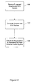
- FIG. 12 is a flow diagram illustrating a method of determining regurgitation.
- FIG. 13 is a flow diagram illustrating another method of determining regurgitation.
- Techniques are described below to improve the measurement and quantification of regurgitation. Techniques of monitoring flow across a valve and evaluating regurgitation through the valve either semi-automatically or automatically are described. Techniques to assess flow across a valve and evaluate regurgitation, even in the case where the flow across the valve is orthogonal to the imaging-line from the transducer, are also described. The techniques described include both semi-automated, and fully-automated estimation of regurgitation. Also, estimating regurgitation can be done real-time, when the data is being acquired, or off-line, that is, storing ultrasound data and processing it later.
- FIG. 1 is an illustration of an ultrasound sector 102 .
- the ultrasound is being used to examine portions of a heart valve.
- the heart valve 104 includes leaflets 106 with blood 108 flowing through the valve 104 and valve leaflets 106 .
- an ultrasound transceiver 110 includes an ultrasound transmitter and an ultrasound receiver, transmits an ultrasound beam 112 , or a plurality of beams.
- a single ultrasound beam can form the entire sector at once, or a narrow beam may be swept through an arc forming the sector, or multiple beams may be transmitted simultaneously to form the sector, or other techniques as is known to those of skill in the art.
- a single instance of an ultrasound beam 112 is illustrated within the sector 102 . As the ultrasound beam 112 propagates through the sector it interacts with the material within its path that includes the heart valve 104 , heart valve leaflets 106 and blood 108 .
- the ultrasound is “range gated” so that only the region of interest 120 around the heart valve leaflets 106 , and the surrounding blood 108 , are examined.
- the region of the sector 102 that the ultrasound beam 112 passes through before and after the area of interest, 122 and 124 respectively, are not examined and not displayed in the Doppler presentation.
- Doppler signals may be obtained from the area of interest 122 that includes a valve being evaluated wherein a relevant majority of the cross-section of the valve is included within the area of interest 120 .
- the signals may be processed to distinguish signals received from blood from those received from tissue, and then different colors may be assigned to the different signals.
- the signals can then be processed in different ways to obtain regurgitation.
- the processed Doppler signals can be correlated to an ECG signal to determine systole and diastole of the heart. The peak reverse flow at systole, such as in the case with interrogation of the atrio-ventricular valves, may then be measured.
- peak forward and reverse flow may be measured during a given cardiac cycle, where the cardiac cycle is identified by a periodic repetition of a peak value, or a pattern of flow, or a positive to negative flow translation in a given direction.
- Regurgitation may then be estimated using the ratio of reverse flow as a percentage of forward flow.
- the forward and reverse flows are given by the area under the respective forward flow and reverse flow curves, normalized for the angle between the ultrasound beam and the blood flow.
- FIG. 2 is a display illustrating a Doppler signal 202 that would be received from the individual components of the heart valve and blood.
- the display has a vertical axis 204 that represents velocity as measured by the Doppler shift of the ultrasound beam as it passes through the area of interest that includes the heart value leaflets and surrounding blood.
- the horizontal axis 206 represents time.
- the Doppler signal 202 includes Doppler information from both the heart tissue, primarily the heart leaflets, 208 and the blood 210 flowing through the leaflet.
- an ECG trace 220 is also included in FIG. 2 .
- the Doppler signals can be correlated to an ECG signal to determine systole and diastole of the heart.
- the peak reverse flow at systole such as in the case with interrogation of the atrio-ventricular valves, may then be measured.
- the spectral Doppler information can be obtained from the ultrasonic interrogation device either as a spectrum, that is digitized line data as a function of time, or digitized images, or the Doppler information may be obtained as an audio signal output which is subsequently digitized and processed to obtain a velocity-time profile Doppler display 202 .
- various frames, or a sampling of frames, that form a real time image may be analyzed as a function of the ECG 220 , with the ECG being utilized to denote the phases of the cardiac cycle.
- the presence or absence of a particular color, and hence directional flow, as indicated by the Doppler display 202 during a particular phase of the cardiac cycle can be detected.
- the number of pixels in the Doppler display that are assigned a particular color and the duration of persistence of that color through the cardiac cycle provides additional information regarding regurgitation.
- the color code for blood flow towards the transducer is graduated in a color scale from red to yellow for increasing velocity up to, for example, 0.8 m/sec.
- the display portion 230 showing regurgitation appears as a red/yellow colored flow emanating out of the atrio-ventricular valve in question.
- FIG. 3 is a block diagram illustrating an ultrasound sector 302 .
- an ultrasound transceiver 110 that includes an ultrasound transmitter and an ultrasound receiver, transmits an ultrasound beam 112 , or a plurality of beams, that are orthogonal to the direction of blood flow 304 .
- range gating techniques are used so that a region of interest 306 around the heart value leaflets 308 , and the surrounding blood 304 , are examined.
- FIG. 4 is a Doppler signal display 402 representing the Doppler signal that would be received from the individual components of the heart valve and blood. As shown in FIG. 4 , the display has a vertical axis 404 that represents velocity as measured by the Doppler bandwidth of backscattered signals. The horizontal axis 408 represents time.
- the Doppler display 402 includes Doppler information from both the heart tissue, primarily the heart leaflets 410 , and the blood 412 flowing through the leaflet. Techniques for estimating velocity based on Doppler bandwidths are known to those of skill in the art. See Tortoli P, Guidi G, Mantovani L, Newhouse V L, “Velocity magnitude estimation with linear arrays using Doppler bandwidth.” Ultrasonics.
- the overall Doppler bandwidth of the spectrum may be determined as a function of systole bandwidth 430 and diastole bandwidth 440 .
- a time-bandwidth profile may then be determined. Regurgitation can be estimated using the ratio of the flow velocity and time product.
- FIG. 5 is a block diagram illustrating an embodiment of a Doppler scanner system 502 constructed in accordance with the present invention.
- the system 502 includes an ultrasound scanner 504 , an ultrasonic transducer 506 , and a display 508 .
- the ultrasound scanner 504 can be capable of intercepting and interpreting Doppler signals.
- the ultrasound scanner 504 may include various circuits and subsystems for performing various functions.
- the ultrasound scanner 506 can include beamformer 510 and transmit/receive 512 circuits or subsystems.
- the ultrasound scanner 504 may also include a Doppler processor 514 , and color flow and other processor 516 .
- the Doppler processor 514 can process spectral Doppler signals as well as process Doppler bandwidth.
- the ultrasound scanner 504 may also include a scan converter 518 and a controller 520 .
- the ultrasound scanner 504 generates signals that are communicated to the ultrasonic transducer 506 .
- the ultrasonic transducer transmits signals and receives reflected signals from a desired sample 522 , for example from a human heart tissue and blood. Signals received by the ultrasonic transducer 506 are communicated to the ultrasound scanner 504 .
- the ultrasound scanner 504 processes the received signals, including color mapping, and the processed signal is provided to the display 508 for presentation to a user.
- the ultrasound scanner 504 processes the received signal and the display 508 includes a processor that processes the signal, for example to perform color mapping, before presentation to a user. Determining regurgitation can be performed in the ultrasound scanner 504 , a processor associated with the display 508 , or both.
- the ultrasound scanner 504 includes a combination of digital or analog electronics capable of generating necessary signals and processing such received signals so as to generate Doppler representations and determine regurgitation in accordance with the invention.
- processing of the Doppler signals and determining regurgitation may be performed in real-time, that is at the time the signals are captured, or off-line following the capture of the data.
- the ultrasonic transducer 506 can include, for example, one or more transducers that utilize piezoelectric properties to generate acoustic signals from electrical signals.
- the transducer may be a mechanical, sector, linear, or curved array design. In general, the type of transducer used is selected to be appropriate for the particular application such as an external application, trans-oesophageal, intra-vascular, intra-cardiac, or endocavitary applications.
- FIG. 6 is a block diagram of the Doppler scanner system of FIG. 5 and includes a workstation 630 .
- the workstation 630 may include hardware and/or software that is separate from the ultrasound scanner 504 .
- the workstation 630 may be in communication with the ultrasound scanner 504 , the display 508 , or both.
- video, audio, or both may be communicated between the ultrasound scanner 504 and the display 508 .
- Communication between the workstation 530 , the display 506 and the ultrasound scanner 504 can include video, audio, Electrocardiogram (ECG) signals, or other types of signals in either digital and/or analog format.
- ECG Electrocardiogram
- FIG. 7 is a block diagram of another embodiment of a Doppler scanner system.
- the workstation 630 communicates only with the ultrasound scanner 504 .
- FIG. 8 is a block diagram of yet another embodiment of a Doppler scanner system.
- the workstation 630 communicates only with the display 508 .
- FIG. 9 is a block diagram illustrating another embodiment of a Doppler scanner system 902 constructed in accordance with the present invention.
- the system 902 includes an ultrasound Doppler processor 904 , an ultrasonic transducer 906 , and a display and control 908 .
- the ultrasound Doppler processor 904 can be capable of intercepting and interpreting Doppler signals.
- the ultrasound Doppler processor 904 may include various circuits and subsystems for performing various functions.
- the ultrasound Doppler processor 906 can include beamformer 910 , transmit/receive 912 circuits or subsystems, and a controller 914 .
- the ultrasound Doppler processor 904 may generate signals that are communicated to the ultrasonic transducer 906 .
- the ultrasonic transducer transmits and receives signals from a desired sample 922 , for example from a human heart tissue and blood. Signals received by the ultrasonic transducer 906 are communicated to the ultrasound Doppler processor 904 .
- the ultrasound Doppler processor 904 processes the received signals, including color mapping, and the processed signal is communicated to the display 908 for presentation to a user.
- the ultrasound Doppler processor 904 does some processing of the received signal and the display 908 includes a process that does some processing of the signal, for example color mapping, before presentation to a user.
- the amount of regurgitation may be determined in the ultrasound Doppler processor 904 , or in a processor in the display 908 , or both. In addition, determination of regurgitation may be determined in a separate workstation, not shown.
- FIG. 10 is a process flow diagram illustrating a system for determining regurgitation.
- An ultrasound scanner 1002 and an ultrasound transducer 1004 obtain ultrasound information from a structure 1006 being imaged, such as a heart value.
- the ultrasound scanner 1002 communicates the ultrasound information to a Doppler processor 1008 .
- the Doppler processor 1008 processes the ultrasound information to differentiate signals received from tissue from those received from blood, and to determine the respective velocities.
- the Doppler processor may determine velocities using Doppler bandwidth estimation techniques.
- ECG processor 1010 Signals from the structure being imaged are also acquired by an ECG processor 1010 .
- the output of the ECG processor and the Doppler processor 1008 are communicated to an ECG Doppler correlator 1012 .
- the ECG Doppler correlator 1012 correlates the ECG and Doppler information, for example, to determine systole and diastole of the heart.
- the correlated information is communicated to a velocity-time curve estimator 1014 where estimates of the velocity, speed and direction, versus time are produced.
- the velocity-time curve estimates are then used in the regurgitation calculation engine 1016 .
- the ECG information, Doppler information, velocity-time curves, and regurgitation calculations may then be presented to a user on a display 1018 . It is noted that any combination of the ECG information, Doppler information, velocity-time curves, and regurgitation calculations may be displayed
- FIG. 11 is a process flow diagram illustrating another embodiment of a system for determining regurgitation.
- the exemplary system of FIG. 11 includes an ultrasound scanner 1002 , ultrasound transducer 1004 , structure being imaged 1006 , ECG processor 1010 , ECG Doppler correlator 1012 , velocity-time curve estimator 1014 , regurgitation calculation engine 1016 , and display that operate in a manner similar to that described in connection with the system illustrated in FIG. 10 .
- the system illustrated in FIG. 11 also includes a color Doppler processor 1102 and a color-angle compensation engine 1104 .
- the color Doppler processor 1102 receives ultrasound information from the ultrasound scanner 1002 and processes the information. Part of the processing by the color Doppler processor includes color coding the Doppler data to indicate speed and direction of flow in accordance with the color used to represent the data.
- the processed Doppler data is communicated to the ECG Doppler correlator 1012 .
- the color-angle compensation engine 1102 receives correlated ECG and Doppler information from the ECG Doppler correlator 1012 and adjusts the color and magnitude of the Doppler data to compensate for the angle between the beam of the ultrasound beam and the direction of the blood flow.
- the angle between the beam of the ultrasound beam and the direction of the blood flow may cause the measured Doppler shift, and corresponding velocity calculation, to be less than the actual Doppler shift that would occur if the angle between the beam and the direction of flow were zero, so that the beam and direction of flow are directly in-line with each other.
- the color-angle compensation engine 1104 adjusts the correlated ECG Doppler data magnitude, and corresponding color, to account for the errors due to the angle between the beam and direction of flow.
- the adjusted ECG Doppler data is communicated to the velocity-time curve estimator 1014 .
- FIG. 12 is a flow diagram illustrating a method of determining regurgitation.
- the method begins in block 1202 where processed Doppler data and ECG signals are received.
- the processed Doppler signals include Doppler data that has been processed to distinguish the power, of amplitude of the spectrum, of the Doppler signal. Color has been assigned in accordance with the Doppler signals received from different types of material and corresponding different signal strengths. For example, different colors can be assigned to Doppler signals received from portions of the heart value versus Doppler signals received from blood.
- Block 1204 Flow continues to Block 1204 .
- the processed Doppler signals and ECG signals are correlated. Correlating the signals can be used, for example, to judge, or determine, the systole and diastole of a heart. Flow then continues to block 1206 where regurgitation is determined by estimating the peak reverse flow through the heart at systole.
- FIG. 13 is a flow diagram illustrating another method of determining regurgitation.
- Flow begins in block 1302 where processed Doppler signals are received.
- the processed Doppler signals include Doppler data that has been processed to distinguish the power, of amplitude of the spectrum, of the Doppler signal and had color assigned in accordance with the Doppler signals received from different types of material. For example, different colors can be assigned to Doppler signals received from portions of the heart value versus Doppler signals received from blood.
- Flow continues to block 1304 .
- the processed Doppler signals are examined to determine the peak forward and reverse flows during a given cardiac cycle.
- the cardiac cycle may be determined in numerous ways. For example, the cardiac cycle may be determined by the periodic repetition of a peak value, or a pattern of flow, or a positive to negative transition in a given direction.
- the forward and reverse flows can be determined in various ways. For example the forward and reverse flows can be estimated by determining the area under the respective forward and reverse flow curves of the Doppler signals. It is beneficial to normalize, or correct, the flow curves according to the angle between the ultrasound beam and the direction of the blood flow.
- Each step in the above flow of determining the phases of the cardiac cycle, of detecting the peak flow velocities, and of judging the angle, can be performed automatically through appropriate processing on a computer, or can be manually performed by the user through the use of one or more user interface techniques, such as demarcating the point on a screen using a mouse or mouse button combination etc.
- DSP digital signal processor
- ASIC application specific integrated circuit
- FPGA field programmable gate array
- a general purpose processor may be a microprocessor, any conventional processor, controller, or micro controller.
- a processor may also be implemented as a combination of computing devices, e.g., a combination of a DSP and a microprocessor, a plurality of microprocessors, one or more microprocessors in conjunction with a DSP core, or any other such configuration.
- Software modules may reside in RAM memory, flash memory, ROM memory, EPROM memory, EEPROM memory, registers, hard disk, a removable disk, a CD-ROM, or any other form of storage medium known in the art.
Abstract
Description
Claims (43)
Priority Applications (1)
| Application Number | Priority Date | Filing Date | Title |
|---|---|---|---|
| US11/302,402 US8070684B2 (en) | 2005-12-14 | 2005-12-14 | Method and system for evaluating valvular function |
Applications Claiming Priority (1)
| Application Number | Priority Date | Filing Date | Title |
|---|---|---|---|
| US11/302,402 US8070684B2 (en) | 2005-12-14 | 2005-12-14 | Method and system for evaluating valvular function |
Publications (2)
| Publication Number | Publication Date |
|---|---|
| US20070167794A1 US20070167794A1 (en) | 2007-07-19 |
| US8070684B2 true US8070684B2 (en) | 2011-12-06 |
Family
ID=38264142
Family Applications (1)
| Application Number | Title | Priority Date | Filing Date |
|---|---|---|---|
| US11/302,402 Expired - Fee Related US8070684B2 (en) | 2005-12-14 | 2005-12-14 | Method and system for evaluating valvular function |
Country Status (1)
| Country | Link |
|---|---|
| US (1) | US8070684B2 (en) |
Cited By (2)
| Publication number | Priority date | Publication date | Assignee | Title |
|---|---|---|---|---|
| US20120136242A1 (en) * | 2010-11-08 | 2012-05-31 | Vasonova, Inc. | Endovascular navigation system and method |
| US10835201B2 (en) | 2017-10-31 | 2020-11-17 | Edwards Lifesciences Corporation | Non-invasive wearable heart valve monitor |
Families Citing this family (4)
| Publication number | Priority date | Publication date | Assignee | Title |
|---|---|---|---|---|
| JP4987295B2 (en) * | 2005-12-26 | 2012-07-25 | 株式会社東芝 | Ultrasonic diagnostic equipment |
| US8696579B2 (en) | 2010-06-04 | 2014-04-15 | Siemens Medical Solutions Usa, Inc. | Cardiac flow quantification with volumetric imaging data |
| US10966686B2 (en) * | 2017-07-14 | 2021-04-06 | Samsung Medison Co., Ltd. | Ultrasound diagnosis apparatus and method of operating the same |
| CN116869571B (en) * | 2023-09-07 | 2023-11-07 | 深圳华声医疗技术股份有限公司 | Ultrasonic heart reflux automatic detection and evaluation method, system and device |
Citations (109)
| Publication number | Priority date | Publication date | Assignee | Title |
|---|---|---|---|---|
| US4161121A (en) | 1976-04-05 | 1979-07-17 | Varian Associates, Inc. | Ultrasonic imaging system |
| US4241610A (en) | 1979-02-05 | 1980-12-30 | Varian Associates, Inc. | Ultrasonic imaging system utilizing dynamic and pseudo-dynamic focusing |
| US4462408A (en) | 1982-05-17 | 1984-07-31 | Advanced Technology Laboratories, Inc. | Ultrasonic endoscope having elongated array mounted in manner allowing it to remain flexible |
| US4519260A (en) | 1982-02-18 | 1985-05-28 | The Board Of Trustees Of The Leland Stanford Junior University | Ultrasonic transducers and applications thereof |
| US4576177A (en) | 1983-02-18 | 1986-03-18 | Webster Wilton W Jr | Catheter for removing arteriosclerotic plaque |
| US4605009A (en) | 1983-04-06 | 1986-08-12 | Universite Francois Rabelais | Ultrasonic sweep echography and display endoscopic probe |
| US4841977A (en) | 1987-05-26 | 1989-06-27 | Inter Therapy, Inc. | Ultra-thin acoustic transducer and balloon catheter using same in imaging array subassembly |
| US4890268A (en) | 1988-12-27 | 1989-12-26 | General Electric Company | Two-dimensional phased array of ultrasonic transducers |
| US4917097A (en) | 1987-10-27 | 1990-04-17 | Endosonics Corporation | Apparatus and method for imaging small cavities |
| US4951677A (en) | 1988-03-21 | 1990-08-28 | Prutech Research And Development Partnership Ii | Acoustic imaging catheter and the like |
| US5002059A (en) | 1989-07-26 | 1991-03-26 | Boston Scientific Corporation | Tip filled ultrasound catheter |
| US5090956A (en) | 1983-10-31 | 1992-02-25 | Catheter Research, Inc. | Catheter with memory element-controlled steering |
| US5105819A (en) | 1988-09-01 | 1992-04-21 | Kon-Tron Elektronik AG | Ultrasound endoscope device |
| US5152294A (en) | 1989-12-14 | 1992-10-06 | Aloka Co., Ltd. | Three-dimensional ultrasonic scanner |
| US5158087A (en) | 1992-01-31 | 1992-10-27 | Hewlett-Packard Company | Differential temperature measurement for ultrasound transducer thermal control |
| US5170793A (en) | 1990-02-07 | 1992-12-15 | Kabushiki Kaisha Toshiba | Ultrasonic probe |
| US5195968A (en) | 1990-02-02 | 1993-03-23 | Ingemar Lundquist | Catheter steering mechanism |
| US5254088A (en) | 1990-02-02 | 1993-10-19 | Ep Technologies, Inc. | Catheter steering mechanism |
| US5279559A (en) | 1992-03-06 | 1994-01-18 | Aai Corporation | Remote steering system for medical catheter |
| US5307816A (en) | 1991-08-21 | 1994-05-03 | Kabushiki Kaisha Toshiba | Thrombus resolving treatment apparatus |
| US5309914A (en) | 1991-04-17 | 1994-05-10 | Kabushiki Kaisha Toshiba | Ultrasonic imaging apparatus |
| US5325860A (en) | 1991-11-08 | 1994-07-05 | Mayo Foundation For Medical Education And Research | Ultrasonic and interventional catheter and method |
| US5345938A (en) | 1991-09-30 | 1994-09-13 | Kabushiki Kaisha Toshiba | Diagnostic apparatus for circulatory systems |
| US5357550A (en) | 1991-09-09 | 1994-10-18 | Kabushiki Kaisha Toshiba | Apparatus for diagnosing vascular systems in organism |
| US5358478A (en) | 1990-02-02 | 1994-10-25 | Ep Technologies, Inc. | Catheter steering assembly providing asymmetric left and right curve configurations |
| US5364351A (en) | 1992-11-13 | 1994-11-15 | Ep Technologies, Inc. | Catheter steering mechanism |
| US5372138A (en) | 1988-03-21 | 1994-12-13 | Boston Scientific Corporation | Acousting imaging catheters and the like |
| US5385148A (en) | 1993-07-30 | 1995-01-31 | The Regents Of The University Of California | Cardiac imaging and ablation catheter |
| US5409010A (en) * | 1992-05-19 | 1995-04-25 | Board Of Regents Of The University Of Washington | Vector doppler medical devices for blood velocity studies |
| US5438997A (en) | 1991-03-13 | 1995-08-08 | Sieben; Wayne | Intravascular imaging apparatus and methods for use and manufacture |
| US5456258A (en) | 1993-12-20 | 1995-10-10 | Fuji Photo Optical Co., Ltd. | Catheter type ultrasound probe |
| US5470350A (en) | 1993-04-02 | 1995-11-28 | Siemens Aktiengesellschaft | System for the treatment of pathological tissue having a catheter with a pressure sensor |
| US5477858A (en) * | 1986-07-30 | 1995-12-26 | Siemens Medical Systems, Inc. | Ultrasound blood flow/tissue imaging system |
| US5499630A (en) | 1993-11-22 | 1996-03-19 | Kabushiki Kaisha Toshiba | Catheter type ultrasound probe |
| US5515853A (en) | 1995-03-28 | 1996-05-14 | Sonometrics Corporation | Three-dimensional digital ultrasound tracking system |
| US5515856A (en) | 1994-08-30 | 1996-05-14 | Vingmed Sound A/S | Method for generating anatomical M-mode displays |
| US5560362A (en) | 1994-06-13 | 1996-10-01 | Acuson Corporation | Active thermal control of ultrasound transducers |
| US5588432A (en) | 1988-03-21 | 1996-12-31 | Boston Scientific Corporation | Catheters for imaging, sensing electrical potentials, and ablating tissue |
| US5622174A (en) | 1992-10-02 | 1997-04-22 | Kabushiki Kaisha Toshiba | Ultrasonic diagnosis apparatus and image displaying system |
| US5662116A (en) | 1995-09-12 | 1997-09-02 | Fuji Photo Optical Co., Ltd. | Multi-plane electronic scan ultrasound probe |
| US5697965A (en) | 1996-04-01 | 1997-12-16 | Procath Corporation | Method of making an atrial defibrillation catheter |
| US5699805A (en) | 1996-06-20 | 1997-12-23 | Mayo Foundation For Medical Education And Research | Longitudinal multiplane ultrasound transducer underfluid catheter system |
| US5704361A (en) | 1991-11-08 | 1998-01-06 | Mayo Foundation For Medical Education And Research | Volumetric image ultrasound transducer underfluid catheter system |
| US5713363A (en) | 1991-11-08 | 1998-02-03 | Mayo Foundation For Medical Education And Research | Ultrasound catheter and method for imaging and hemodynamic monitoring |
| US5715817A (en) | 1993-06-29 | 1998-02-10 | C.R. Bard, Inc. | Bidirectional steering catheter |
| US5722403A (en) | 1996-10-28 | 1998-03-03 | Ep Technologies, Inc. | Systems and methods using a porous electrode for ablating and visualizing interior tissue regions |
| US5749364A (en) | 1996-06-21 | 1998-05-12 | Acuson Corporation | Method and apparatus for mapping pressure and tissue properties |
| US5788636A (en) | 1997-02-25 | 1998-08-04 | Acuson Corporation | Method and system for forming an ultrasound image of a tissue while simultaneously ablating the tissue |
| US5795299A (en) | 1997-01-31 | 1998-08-18 | Acuson Corporation | Ultrasonic transducer assembly with extended flexible circuits |
| US5797848A (en) | 1997-01-31 | 1998-08-25 | Acuson Corporation | Ultrasonic transducer assembly with improved electrical interface |
| US5800356A (en) | 1997-05-29 | 1998-09-01 | Advanced Technology Laboratories, Inc. | Ultrasonic diagnostic imaging system with doppler assisted tracking of tissue motion |
| US5807324A (en) | 1996-04-01 | 1998-09-15 | Procath Corporation | Steerable catheter |
| US5846205A (en) | 1997-01-31 | 1998-12-08 | Acuson Corporation | Catheter-mounted, phased-array ultrasound transducer with improved imaging |
| US5888577A (en) | 1997-06-30 | 1999-03-30 | Procath Corporation | Method for forming an electrophysiology catheter |
| US5891088A (en) | 1990-02-02 | 1999-04-06 | Ep Technologies, Inc. | Catheter steering assembly providing asymmetric left and right curve configurations |
| US5906579A (en) | 1996-08-16 | 1999-05-25 | Smith & Nephew Endoscopy, Inc. | Through-wall catheter steering and positioning |
| US5916168A (en) | 1997-05-29 | 1999-06-29 | Advanced Technology Laboratories, Inc. | Three dimensional M-mode ultrasonic diagnostic imaging system |
| US5921978A (en) | 1997-06-20 | 1999-07-13 | Ep Technologies, Inc. | Catheter tip steering plane marker |
| US5928276A (en) | 1998-06-11 | 1999-07-27 | Griffin, Iii; Joseph C. | Combined cable and electrophysiology catheters |
| US5931863A (en) | 1997-12-22 | 1999-08-03 | Procath Corporation | Electrophysiology catheter |
| US5935102A (en) | 1993-05-14 | 1999-08-10 | C. R. Bard | Steerable electrode catheter |
| US5938616A (en) | 1997-01-31 | 1999-08-17 | Acuson Corporation | Steering mechanism and steering line for a catheter-mounted ultrasonic transducer |
| US5954654A (en) | 1997-01-31 | 1999-09-21 | Acuson Corporation | Steering mechanism and steering line for a catheter-mounted ultrasonic transducer |
| US6013072A (en) | 1997-07-09 | 2000-01-11 | Intraluminal Therapeutics, Inc. | Systems and methods for steering a catheter through body tissue |
| US6033378A (en) | 1990-02-02 | 2000-03-07 | Ep Technologies, Inc. | Catheter steering mechanism |
| US6144870A (en) | 1996-10-21 | 2000-11-07 | Procath Corporation | Catheter with improved electrodes and method of fabrication |
| US6171248B1 (en) | 1997-02-27 | 2001-01-09 | Acuson Corporation | Ultrasonic probe, system and method for two-dimensional imaging or three-dimensional reconstruction |
| US6190353B1 (en) | 1995-10-13 | 2001-02-20 | Transvascular, Inc. | Methods and apparatus for bypassing arterial obstructions and/or performing other transvascular procedures |
| US6210333B1 (en) | 1999-10-12 | 2001-04-03 | Acuson Corporation | Medical diagnostic ultrasound system and method for automated triggered intervals |
| US6224556B1 (en) | 1998-11-25 | 2001-05-01 | Acuson Corporation | Diagnostic medical ultrasound system and method for using a sparse array |
| US6228028B1 (en) | 1996-11-07 | 2001-05-08 | Tomtec Imaging Systems Gmbh | Method and apparatus for ultrasound image reconstruction |
| US6261246B1 (en) | 1997-09-29 | 2001-07-17 | Scimed Life Systems, Inc. | Intravascular imaging guidewire |
| US6293943B1 (en) | 1995-06-07 | 2001-09-25 | Ep Technologies, Inc. | Tissue heating and ablation systems and methods which predict maximum tissue temperature |
| US6306097B1 (en) | 1999-06-17 | 2001-10-23 | Acuson Corporation | Ultrasound imaging catheter guiding assembly with catheter working port |
| US6310828B1 (en) | 1997-07-18 | 2001-10-30 | Tomtec Imaging Systems Gmbh | Method and device for sensing ultrasound images |
| US6358208B1 (en) | 1998-11-21 | 2002-03-19 | Philipp Lang | Assessment of cardiovascular performance using ultrasound methods and devices that interrogate interstitial fluid |
| US6360027B1 (en) | 1996-02-29 | 2002-03-19 | Acuson Corporation | Multiple ultrasound image registration system, method and transducer |
| US6368275B1 (en) | 1999-10-07 | 2002-04-09 | Acuson Corporation | Method and apparatus for diagnostic medical information gathering, hyperthermia treatment, or directed gene therapy |
| US6385489B1 (en) | 1998-09-25 | 2002-05-07 | Ep Medsystems, Inc. | Triple array defibrillation catheter and method of using the same |
| US6398731B1 (en) | 1997-07-25 | 2002-06-04 | Tomtec Imaging Systems Gmbh | Method for recording ultrasound images of moving objects |
| US6423002B1 (en) | 1999-06-24 | 2002-07-23 | Acuson Corporation | Intra-operative diagnostic ultrasound multiple-array transducer probe and optional surgical tool |
| US6440488B2 (en) | 1999-12-03 | 2002-08-27 | Ep Medsystems, Inc. | Flexible electrode catheter and process for manufacturing the same |
| US6443894B1 (en) | 1999-09-29 | 2002-09-03 | Acuson Corporation | Medical diagnostic ultrasound system and method for mapping surface data for three dimensional imaging |
| US6475149B1 (en) | 2001-09-21 | 2002-11-05 | Acuson Corporation | Border detection method and system |
| US6475148B1 (en) | 2000-10-25 | 2002-11-05 | Acuson Corporation | Medical diagnostic ultrasound-aided drug delivery system and method |
| US6482161B1 (en) | 2000-06-29 | 2002-11-19 | Acuson Corporation | Medical diagnostic ultrasound system and method for vessel structure analysis |
| US6491633B1 (en) | 2000-03-10 | 2002-12-10 | Acuson Corporation | Medical diagnostic ultrasound system and method for contrast agent image beamformation |
| US6503202B1 (en) | 2000-06-29 | 2003-01-07 | Acuson Corp. | Medical diagnostic ultrasound system and method for flow analysis |
| US6517488B1 (en) | 2000-06-29 | 2003-02-11 | Acuson Corporation | Medical diagnostic ultrasound system and method for identifying constrictions |
| US6527717B1 (en) | 2000-03-10 | 2003-03-04 | Acuson Corporation | Tissue motion analysis medical diagnostic ultrasound system and method |
| US20030045796A1 (en) | 2001-08-31 | 2003-03-06 | Friedman Zvi M. | Ultrasonic monitoring system and method |
| US6532378B2 (en) | 2000-01-14 | 2003-03-11 | Ep Medsystems, Inc. | Pulmonary artery catheter for left and right atrial recording |
| US6544181B1 (en) * | 1999-03-05 | 2003-04-08 | The General Hospital Corporation | Method and apparatus for measuring volume flow and area for a dynamic orifice |
| US6554770B1 (en) | 1998-11-20 | 2003-04-29 | Acuson Corporation | Medical diagnostic ultrasound imaging methods for extended field of view |
| US6589182B1 (en) | 2001-02-12 | 2003-07-08 | Acuson Corporation | Medical diagnostic ultrasound catheter with first and second tip portions |
| US6605043B1 (en) | 1998-11-19 | 2003-08-12 | Acuson Corp. | Diagnostic medical ultrasound systems and transducers utilizing micro-mechanical components |
| US6607488B1 (en) | 2000-03-02 | 2003-08-19 | Acuson Corporation | Medical diagnostic ultrasound system and method for scanning plane orientation |
| US6607528B1 (en) | 1999-06-22 | 2003-08-19 | Senorx, Inc. | Shapeable electrosurgical scalpel |
| US6612992B1 (en) | 2000-03-02 | 2003-09-02 | Acuson Corp | Medical diagnostic ultrasound catheter and method for position determination |
| US6645147B1 (en) | 1998-11-25 | 2003-11-11 | Acuson Corporation | Diagnostic medical ultrasound image and system for contrast agent imaging |
| US6648875B2 (en) | 2001-05-04 | 2003-11-18 | Cardiac Pacemakers, Inc. | Means for maintaining tension on a steering tendon in a steerable catheter |
| US6709396B2 (en) | 2002-07-17 | 2004-03-23 | Vermon | Ultrasound array transducer for catheter use |
| US20040097805A1 (en) | 2002-11-19 | 2004-05-20 | Laurent Verard | Navigation system for cardiac therapies |
| US20040127798A1 (en) * | 2002-07-22 | 2004-07-01 | Ep Medsystems, Inc. | Method and system for using ultrasound in cardiac diagnosis and therapy |
| US20040249282A1 (en) | 2003-06-09 | 2004-12-09 | Bjorn Olstad | System and method for extracting information based on ultrasound-located landmarks |
| US20040254483A1 (en) * | 2003-01-24 | 2004-12-16 | Proteus Biomedical, Inc. | Methods and systems for measuring cardiac parameters |
| US6908434B1 (en) | 2002-01-16 | 2005-06-21 | Ep Medsystems, Inc. | Ultrasound imaging catheter isolation system with temperature sensor |
| US6923768B2 (en) | 2002-03-11 | 2005-08-02 | Siemens Aktiengesellschaft | Method and apparatus for acquiring and displaying a medical instrument introduced into a cavity organ of a patient to be examined or treated |
| US20050203390A1 (en) | 1999-08-23 | 2005-09-15 | Hans Torp | Method and apparatus for providing real-time calculation and display of tissue deformation in ultrasound imaging |
-
2005
- 2005-12-14 US US11/302,402 patent/US8070684B2/en not_active Expired - Fee Related
Patent Citations (123)
| Publication number | Priority date | Publication date | Assignee | Title |
|---|---|---|---|---|
| US4161121A (en) | 1976-04-05 | 1979-07-17 | Varian Associates, Inc. | Ultrasonic imaging system |
| US4241610A (en) | 1979-02-05 | 1980-12-30 | Varian Associates, Inc. | Ultrasonic imaging system utilizing dynamic and pseudo-dynamic focusing |
| US4519260A (en) | 1982-02-18 | 1985-05-28 | The Board Of Trustees Of The Leland Stanford Junior University | Ultrasonic transducers and applications thereof |
| US4462408A (en) | 1982-05-17 | 1984-07-31 | Advanced Technology Laboratories, Inc. | Ultrasonic endoscope having elongated array mounted in manner allowing it to remain flexible |
| US4576177A (en) | 1983-02-18 | 1986-03-18 | Webster Wilton W Jr | Catheter for removing arteriosclerotic plaque |
| US4605009A (en) | 1983-04-06 | 1986-08-12 | Universite Francois Rabelais | Ultrasonic sweep echography and display endoscopic probe |
| US5090956A (en) | 1983-10-31 | 1992-02-25 | Catheter Research, Inc. | Catheter with memory element-controlled steering |
| US5477858A (en) * | 1986-07-30 | 1995-12-26 | Siemens Medical Systems, Inc. | Ultrasound blood flow/tissue imaging system |
| US4841977A (en) | 1987-05-26 | 1989-06-27 | Inter Therapy, Inc. | Ultra-thin acoustic transducer and balloon catheter using same in imaging array subassembly |
| US4917097A (en) | 1987-10-27 | 1990-04-17 | Endosonics Corporation | Apparatus and method for imaging small cavities |
| US4951677A (en) | 1988-03-21 | 1990-08-28 | Prutech Research And Development Partnership Ii | Acoustic imaging catheter and the like |
| US5588432A (en) | 1988-03-21 | 1996-12-31 | Boston Scientific Corporation | Catheters for imaging, sensing electrical potentials, and ablating tissue |
| US5372138A (en) | 1988-03-21 | 1994-12-13 | Boston Scientific Corporation | Acousting imaging catheters and the like |
| US5105819A (en) | 1988-09-01 | 1992-04-21 | Kon-Tron Elektronik AG | Ultrasound endoscope device |
| US4890268A (en) | 1988-12-27 | 1989-12-26 | General Electric Company | Two-dimensional phased array of ultrasonic transducers |
| US5002059A (en) | 1989-07-26 | 1991-03-26 | Boston Scientific Corporation | Tip filled ultrasound catheter |
| US5152294A (en) | 1989-12-14 | 1992-10-06 | Aloka Co., Ltd. | Three-dimensional ultrasonic scanner |
| US5395327A (en) | 1990-02-02 | 1995-03-07 | Ep Technologies, Inc. | Catheter steering mechanism |
| US5358478A (en) | 1990-02-02 | 1994-10-25 | Ep Technologies, Inc. | Catheter steering assembly providing asymmetric left and right curve configurations |
| US5531686A (en) | 1990-02-02 | 1996-07-02 | Ep Technologies, Inc. | Catheter steering mechanism |
| US5891088A (en) | 1990-02-02 | 1999-04-06 | Ep Technologies, Inc. | Catheter steering assembly providing asymmetric left and right curve configurations |
| US6033378A (en) | 1990-02-02 | 2000-03-07 | Ep Technologies, Inc. | Catheter steering mechanism |
| US5336182A (en) | 1990-02-02 | 1994-08-09 | Ep Technologies, Inc. | Catheter steering mechanism |
| US6485455B1 (en) | 1990-02-02 | 2002-11-26 | Ep Technologies, Inc. | Catheter steering assembly providing asymmetric left and right curve configurations |
| US5195968A (en) | 1990-02-02 | 1993-03-23 | Ingemar Lundquist | Catheter steering mechanism |
| US5254088A (en) | 1990-02-02 | 1993-10-19 | Ep Technologies, Inc. | Catheter steering mechanism |
| US5170793A (en) | 1990-02-07 | 1992-12-15 | Kabushiki Kaisha Toshiba | Ultrasonic probe |
| US5438997A (en) | 1991-03-13 | 1995-08-08 | Sieben; Wayne | Intravascular imaging apparatus and methods for use and manufacture |
| US5309914A (en) | 1991-04-17 | 1994-05-10 | Kabushiki Kaisha Toshiba | Ultrasonic imaging apparatus |
| US5307816A (en) | 1991-08-21 | 1994-05-03 | Kabushiki Kaisha Toshiba | Thrombus resolving treatment apparatus |
| US5357550A (en) | 1991-09-09 | 1994-10-18 | Kabushiki Kaisha Toshiba | Apparatus for diagnosing vascular systems in organism |
| US5345938A (en) | 1991-09-30 | 1994-09-13 | Kabushiki Kaisha Toshiba | Diagnostic apparatus for circulatory systems |
| US5345940A (en) | 1991-11-08 | 1994-09-13 | Mayo Foundation For Medical Education And Research | Transvascular ultrasound hemodynamic and interventional catheter and method |
| US6039693A (en) | 1991-11-08 | 2000-03-21 | Mayo Foundation For Medical Education And Research | Volumetric image ultrasound transducer underfluid catheter system |
| US6306096B1 (en) | 1991-11-08 | 2001-10-23 | Mayo Foundation For Medical Education And Research | Volumetric image ultrasound transducer underfluid catheter system |
| US5325860A (en) | 1991-11-08 | 1994-07-05 | Mayo Foundation For Medical Education And Research | Ultrasonic and interventional catheter and method |
| US5713363A (en) | 1991-11-08 | 1998-02-03 | Mayo Foundation For Medical Education And Research | Ultrasound catheter and method for imaging and hemodynamic monitoring |
| US5704361A (en) | 1991-11-08 | 1998-01-06 | Mayo Foundation For Medical Education And Research | Volumetric image ultrasound transducer underfluid catheter system |
| US5158087A (en) | 1992-01-31 | 1992-10-27 | Hewlett-Packard Company | Differential temperature measurement for ultrasound transducer thermal control |
| US5279559A (en) | 1992-03-06 | 1994-01-18 | Aai Corporation | Remote steering system for medical catheter |
| US5409010A (en) * | 1992-05-19 | 1995-04-25 | Board Of Regents Of The University Of Washington | Vector doppler medical devices for blood velocity studies |
| US5701897A (en) | 1992-10-02 | 1997-12-30 | Kabushiki Kaisha Toshiba | Ultrasonic diagnosis apparatus and image displaying system |
| US5622174A (en) | 1992-10-02 | 1997-04-22 | Kabushiki Kaisha Toshiba | Ultrasonic diagnosis apparatus and image displaying system |
| US5456664A (en) | 1992-11-13 | 1995-10-10 | Ep Technologies, Inc. | Catheter steering mechanism |
| US5364351A (en) | 1992-11-13 | 1994-11-15 | Ep Technologies, Inc. | Catheter steering mechanism |
| US5470350A (en) | 1993-04-02 | 1995-11-28 | Siemens Aktiengesellschaft | System for the treatment of pathological tissue having a catheter with a pressure sensor |
| US5935102A (en) | 1993-05-14 | 1999-08-10 | C. R. Bard | Steerable electrode catheter |
| US5715817A (en) | 1993-06-29 | 1998-02-10 | C.R. Bard, Inc. | Bidirectional steering catheter |
| US5385148A (en) | 1993-07-30 | 1995-01-31 | The Regents Of The University Of California | Cardiac imaging and ablation catheter |
| US5499630A (en) | 1993-11-22 | 1996-03-19 | Kabushiki Kaisha Toshiba | Catheter type ultrasound probe |
| US5456258A (en) | 1993-12-20 | 1995-10-10 | Fuji Photo Optical Co., Ltd. | Catheter type ultrasound probe |
| US5560362A (en) | 1994-06-13 | 1996-10-01 | Acuson Corporation | Active thermal control of ultrasound transducers |
| US5515856A (en) | 1994-08-30 | 1996-05-14 | Vingmed Sound A/S | Method for generating anatomical M-mode displays |
| US5515853A (en) | 1995-03-28 | 1996-05-14 | Sonometrics Corporation | Three-dimensional digital ultrasound tracking system |
| US6293943B1 (en) | 1995-06-07 | 2001-09-25 | Ep Technologies, Inc. | Tissue heating and ablation systems and methods which predict maximum tissue temperature |
| US5662116A (en) | 1995-09-12 | 1997-09-02 | Fuji Photo Optical Co., Ltd. | Multi-plane electronic scan ultrasound probe |
| US6190353B1 (en) | 1995-10-13 | 2001-02-20 | Transvascular, Inc. | Methods and apparatus for bypassing arterial obstructions and/or performing other transvascular procedures |
| US6360027B1 (en) | 1996-02-29 | 2002-03-19 | Acuson Corporation | Multiple ultrasound image registration system, method and transducer |
| US5807324A (en) | 1996-04-01 | 1998-09-15 | Procath Corporation | Steerable catheter |
| US5697965A (en) | 1996-04-01 | 1997-12-16 | Procath Corporation | Method of making an atrial defibrillation catheter |
| US5699805A (en) | 1996-06-20 | 1997-12-23 | Mayo Foundation For Medical Education And Research | Longitudinal multiplane ultrasound transducer underfluid catheter system |
| US5749364A (en) | 1996-06-21 | 1998-05-12 | Acuson Corporation | Method and apparatus for mapping pressure and tissue properties |
| US5906579A (en) | 1996-08-16 | 1999-05-25 | Smith & Nephew Endoscopy, Inc. | Through-wall catheter steering and positioning |
| US6144870A (en) | 1996-10-21 | 2000-11-07 | Procath Corporation | Catheter with improved electrodes and method of fabrication |
| US5722403A (en) | 1996-10-28 | 1998-03-03 | Ep Technologies, Inc. | Systems and methods using a porous electrode for ablating and visualizing interior tissue regions |
| US6228028B1 (en) | 1996-11-07 | 2001-05-08 | Tomtec Imaging Systems Gmbh | Method and apparatus for ultrasound image reconstruction |
| US5846205A (en) | 1997-01-31 | 1998-12-08 | Acuson Corporation | Catheter-mounted, phased-array ultrasound transducer with improved imaging |
| US5954654A (en) | 1997-01-31 | 1999-09-21 | Acuson Corporation | Steering mechanism and steering line for a catheter-mounted ultrasonic transducer |
| US6228032B1 (en) | 1997-01-31 | 2001-05-08 | Acuson Corporation | Steering mechanism and steering line for a catheter-mounted ultrasonic transducer |
| US5795299A (en) | 1997-01-31 | 1998-08-18 | Acuson Corporation | Ultrasonic transducer assembly with extended flexible circuits |
| US5797848A (en) | 1997-01-31 | 1998-08-25 | Acuson Corporation | Ultrasonic transducer assembly with improved electrical interface |
| US5938616A (en) | 1997-01-31 | 1999-08-17 | Acuson Corporation | Steering mechanism and steering line for a catheter-mounted ultrasonic transducer |
| US5788636A (en) | 1997-02-25 | 1998-08-04 | Acuson Corporation | Method and system for forming an ultrasound image of a tissue while simultaneously ablating the tissue |
| US6171248B1 (en) | 1997-02-27 | 2001-01-09 | Acuson Corporation | Ultrasonic probe, system and method for two-dimensional imaging or three-dimensional reconstruction |
| US5800356A (en) | 1997-05-29 | 1998-09-01 | Advanced Technology Laboratories, Inc. | Ultrasonic diagnostic imaging system with doppler assisted tracking of tissue motion |
| US5916168A (en) | 1997-05-29 | 1999-06-29 | Advanced Technology Laboratories, Inc. | Three dimensional M-mode ultrasonic diagnostic imaging system |
| US5921978A (en) | 1997-06-20 | 1999-07-13 | Ep Technologies, Inc. | Catheter tip steering plane marker |
| US5888577A (en) | 1997-06-30 | 1999-03-30 | Procath Corporation | Method for forming an electrophysiology catheter |
| US6013072A (en) | 1997-07-09 | 2000-01-11 | Intraluminal Therapeutics, Inc. | Systems and methods for steering a catheter through body tissue |
| US6310828B1 (en) | 1997-07-18 | 2001-10-30 | Tomtec Imaging Systems Gmbh | Method and device for sensing ultrasound images |
| US6398731B1 (en) | 1997-07-25 | 2002-06-04 | Tomtec Imaging Systems Gmbh | Method for recording ultrasound images of moving objects |
| US6261246B1 (en) | 1997-09-29 | 2001-07-17 | Scimed Life Systems, Inc. | Intravascular imaging guidewire |
| US5931863A (en) | 1997-12-22 | 1999-08-03 | Procath Corporation | Electrophysiology catheter |
| US6173205B1 (en) | 1997-12-22 | 2001-01-09 | Procath Corporation | Electrophysiology catheter |
| US6085117A (en) | 1997-12-22 | 2000-07-04 | Procath Corporation | Method of defibrillating employing coronary sinus and external patch electrodes |
| US5928276A (en) | 1998-06-11 | 1999-07-27 | Griffin, Iii; Joseph C. | Combined cable and electrophysiology catheters |
| US6385489B1 (en) | 1998-09-25 | 2002-05-07 | Ep Medsystems, Inc. | Triple array defibrillation catheter and method of using the same |
| US6605043B1 (en) | 1998-11-19 | 2003-08-12 | Acuson Corp. | Diagnostic medical ultrasound systems and transducers utilizing micro-mechanical components |
| US6554770B1 (en) | 1998-11-20 | 2003-04-29 | Acuson Corporation | Medical diagnostic ultrasound imaging methods for extended field of view |
| US6358208B1 (en) | 1998-11-21 | 2002-03-19 | Philipp Lang | Assessment of cardiovascular performance using ultrasound methods and devices that interrogate interstitial fluid |
| US6645147B1 (en) | 1998-11-25 | 2003-11-11 | Acuson Corporation | Diagnostic medical ultrasound image and system for contrast agent imaging |
| US6224556B1 (en) | 1998-11-25 | 2001-05-01 | Acuson Corporation | Diagnostic medical ultrasound system and method for using a sparse array |
| US6544181B1 (en) * | 1999-03-05 | 2003-04-08 | The General Hospital Corporation | Method and apparatus for measuring volume flow and area for a dynamic orifice |
| US20030109785A1 (en) * | 1999-03-05 | 2003-06-12 | The General Hospital Corporation | Method and apparatus for measuring volume flow and area for a dynamic orifice |
| US6306097B1 (en) | 1999-06-17 | 2001-10-23 | Acuson Corporation | Ultrasound imaging catheter guiding assembly with catheter working port |
| US6607528B1 (en) | 1999-06-22 | 2003-08-19 | Senorx, Inc. | Shapeable electrosurgical scalpel |
| US6423002B1 (en) | 1999-06-24 | 2002-07-23 | Acuson Corporation | Intra-operative diagnostic ultrasound multiple-array transducer probe and optional surgical tool |
| US20050203390A1 (en) | 1999-08-23 | 2005-09-15 | Hans Torp | Method and apparatus for providing real-time calculation and display of tissue deformation in ultrasound imaging |
| US6443894B1 (en) | 1999-09-29 | 2002-09-03 | Acuson Corporation | Medical diagnostic ultrasound system and method for mapping surface data for three dimensional imaging |
| US6368275B1 (en) | 1999-10-07 | 2002-04-09 | Acuson Corporation | Method and apparatus for diagnostic medical information gathering, hyperthermia treatment, or directed gene therapy |
| US6210333B1 (en) | 1999-10-12 | 2001-04-03 | Acuson Corporation | Medical diagnostic ultrasound system and method for automated triggered intervals |
| US6440488B2 (en) | 1999-12-03 | 2002-08-27 | Ep Medsystems, Inc. | Flexible electrode catheter and process for manufacturing the same |
| US6532378B2 (en) | 2000-01-14 | 2003-03-11 | Ep Medsystems, Inc. | Pulmonary artery catheter for left and right atrial recording |
| US6612992B1 (en) | 2000-03-02 | 2003-09-02 | Acuson Corp | Medical diagnostic ultrasound catheter and method for position determination |
| US6607488B1 (en) | 2000-03-02 | 2003-08-19 | Acuson Corporation | Medical diagnostic ultrasound system and method for scanning plane orientation |
| US6527717B1 (en) | 2000-03-10 | 2003-03-04 | Acuson Corporation | Tissue motion analysis medical diagnostic ultrasound system and method |
| US6491633B1 (en) | 2000-03-10 | 2002-12-10 | Acuson Corporation | Medical diagnostic ultrasound system and method for contrast agent image beamformation |
| US20030158483A1 (en) | 2000-03-10 | 2003-08-21 | Acuson Corporation | Tissue motion analysis medical diagnostic ultrasound system and method |
| US6517488B1 (en) | 2000-06-29 | 2003-02-11 | Acuson Corporation | Medical diagnostic ultrasound system and method for identifying constrictions |
| US6503202B1 (en) | 2000-06-29 | 2003-01-07 | Acuson Corp. | Medical diagnostic ultrasound system and method for flow analysis |
| US6482161B1 (en) | 2000-06-29 | 2002-11-19 | Acuson Corporation | Medical diagnostic ultrasound system and method for vessel structure analysis |
| US6475148B1 (en) | 2000-10-25 | 2002-11-05 | Acuson Corporation | Medical diagnostic ultrasound-aided drug delivery system and method |
| US6589182B1 (en) | 2001-02-12 | 2003-07-08 | Acuson Corporation | Medical diagnostic ultrasound catheter with first and second tip portions |
| US6648875B2 (en) | 2001-05-04 | 2003-11-18 | Cardiac Pacemakers, Inc. | Means for maintaining tension on a steering tendon in a steerable catheter |
| US20030045796A1 (en) | 2001-08-31 | 2003-03-06 | Friedman Zvi M. | Ultrasonic monitoring system and method |
| US6475149B1 (en) | 2001-09-21 | 2002-11-05 | Acuson Corporation | Border detection method and system |
| US6908434B1 (en) | 2002-01-16 | 2005-06-21 | Ep Medsystems, Inc. | Ultrasound imaging catheter isolation system with temperature sensor |
| US6923768B2 (en) | 2002-03-11 | 2005-08-02 | Siemens Aktiengesellschaft | Method and apparatus for acquiring and displaying a medical instrument introduced into a cavity organ of a patient to be examined or treated |
| US6709396B2 (en) | 2002-07-17 | 2004-03-23 | Vermon | Ultrasound array transducer for catheter use |
| US20040127798A1 (en) * | 2002-07-22 | 2004-07-01 | Ep Medsystems, Inc. | Method and system for using ultrasound in cardiac diagnosis and therapy |
| US20040097805A1 (en) | 2002-11-19 | 2004-05-20 | Laurent Verard | Navigation system for cardiac therapies |
| US20040254483A1 (en) * | 2003-01-24 | 2004-12-16 | Proteus Biomedical, Inc. | Methods and systems for measuring cardiac parameters |
| US20040249282A1 (en) | 2003-06-09 | 2004-12-09 | Bjorn Olstad | System and method for extracting information based on ultrasound-located landmarks |
Non-Patent Citations (45)
Cited By (6)
| Publication number | Priority date | Publication date | Assignee | Title |
|---|---|---|---|---|
| US20120136242A1 (en) * | 2010-11-08 | 2012-05-31 | Vasonova, Inc. | Endovascular navigation system and method |
| US9119551B2 (en) * | 2010-11-08 | 2015-09-01 | Vasonova, Inc. | Endovascular navigation system and method |
| US10368830B2 (en) | 2010-11-08 | 2019-08-06 | Arrow International Inc. | Endovascular navigation system and method |
| US11445996B2 (en) | 2010-11-08 | 2022-09-20 | Teleflex Life Sciences Limited | Endovascular navigation system and method |
| US10835201B2 (en) | 2017-10-31 | 2020-11-17 | Edwards Lifesciences Corporation | Non-invasive wearable heart valve monitor |
| US11723621B2 (en) | 2017-10-31 | 2023-08-15 | Edwards Lifesciences Corporation | Heart valve monitoring |
Also Published As
| Publication number | Publication date |
|---|---|
| US20070167794A1 (en) | 2007-07-19 |
Similar Documents
| Publication | Publication Date | Title |
|---|---|---|
| US6544181B1 (en) | Method and apparatus for measuring volume flow and area for a dynamic orifice | |
| US7245746B2 (en) | Ultrasound color characteristic mapping | |
| US8094893B2 (en) | Segmentation tool for identifying flow regions in an image system | |
| JP4574551B2 (en) | Ultrasonic diagnostic equipment | |
| US20110208056A1 (en) | Volumetric Quantification for Ultrasound Diagnostic Imaging | |
| US20040249281A1 (en) | Method and apparatus for extracting wall function information relative to ultrasound-located landmarks | |
| US8070684B2 (en) | Method and system for evaluating valvular function | |
| WO2009118798A1 (en) | Ultrasonograph | |
| JP4602906B2 (en) | Ultrasonic diagnostic equipment | |
| US6258031B1 (en) | Ultrasound diagnostic apparatus | |
| RU2569695C2 (en) | Analysing mitral insufficiency by ultrasonic imaging | |
| WO2015125353A1 (en) | Ultrasonic diagnostic device | |
| WO2021042298A1 (en) | Vti measuring device and method | |
| US8926516B2 (en) | Ultrasound imaging apparatus and method of ultrasound imaging | |
| EP1003051A2 (en) | Ultrasonic imaging apparatus | |
| US20210369236A1 (en) | Methods and systems for performing transvalvular pressure quantification | |
| RU2589627C2 (en) | Automated identification of position of regurgitation hole of mitral valve on ultrasonic image | |
| CN115770062A (en) | Ultrasonic data processing method and imaging device | |
| JP2009039277A (en) | Ultrasonic diagnostic apparatus | |
| US11642098B2 (en) | Ultrasonic imaging apparatus and method of controlling the same | |
| US11109841B2 (en) | Method and system for simultaneously presenting doppler signals of a multi-gated doppler signal corresponding with different anatomical structures | |
| Mele et al. | A semiautomated objective technique for applying the proximal isovelocity surface area method to quantitate mitral regurgitation: clinical studies with the digital flow map | |
| US20220079550A1 (en) | Methods and systems for monitoring a function of a heart | |
| Kitabatake et al. | Current development in Doppler echocardiography: the real-time two-dimensional Doppler flow imaging system | |
| Veyrat et al. | Flow mapping of regurgitant jets in mitral valve prolapse |
Legal Events
| Date | Code | Title | Description |
|---|---|---|---|
| AS | Assignment |
Owner name: EP MEDSYSTEMS, INC., NEW JERSEY Free format text: ASSIGNMENT OF ASSIGNORS INTEREST;ASSIGNOR:KRISHNA, PRAVEEN DALA;REEL/FRAME:017173/0906 Effective date: 20060214 |
|
| AS | Assignment |
Owner name: KELTIC FINANCIAL PARTNERS, LP, NEW YORK Free format text: SECURITY AGREEMENT;ASSIGNOR:EP MEDSYSTEMS, INC.;REEL/FRAME:020599/0373 Effective date: 20080228 Owner name: KELTIC FINANCIAL PARTNERS, LP,NEW YORK Free format text: SECURITY AGREEMENT;ASSIGNOR:EP MEDSYSTEMS, INC.;REEL/FRAME:020599/0373 Effective date: 20080228 |
|
| AS | Assignment |
Owner name: KELTIC FINANCIAL PARTNERS, LP, NEW YORK Free format text: RELEASE BY SECURED PARTY;ASSIGNOR:EP MEDSYSTEMS, INC.;REEL/FRAME:021243/0030 Effective date: 20080710 Owner name: KELTIC FINANCIAL PARTNERS, LP,NEW YORK Free format text: RELEASE BY SECURED PARTY;ASSIGNOR:EP MEDSYSTEMS, INC.;REEL/FRAME:021243/0030 Effective date: 20080710 |
|
| AS | Assignment |
Owner name: EP MEDSYSTEMS LLC, MINNESOTA Free format text: MERGER;ASSIGNOR:EP MEDSYSTEMS, INC.;REEL/FRAME:025852/0708 Effective date: 20080703 |
|
| AS | Assignment |
Owner name: ST. JUDE MEDICAL, ATRIAL FIBRILLATION DIVISION, IN Free format text: ASSIGNMENT OF ASSIGNORS INTEREST;ASSIGNOR:EP MEDSYSTEMS LLC;REEL/FRAME:025923/0450 Effective date: 20080708 |
|
| STCF | Information on status: patent grant |
Free format text: PATENTED CASE |
|
| FEPP | Fee payment procedure |
Free format text: PAT HOLDER NO LONGER CLAIMS SMALL ENTITY STATUS, ENTITY STATUS SET TO UNDISCOUNTED (ORIGINAL EVENT CODE: STOL); ENTITY STATUS OF PATENT OWNER: LARGE ENTITY |
|
| FPAY | Fee payment |
Year of fee payment: 4 |
|
| FEPP | Fee payment procedure |
Free format text: MAINTENANCE FEE REMINDER MAILED (ORIGINAL EVENT CODE: REM.); ENTITY STATUS OF PATENT OWNER: LARGE ENTITY |
|
| LAPS | Lapse for failure to pay maintenance fees |
Free format text: PATENT EXPIRED FOR FAILURE TO PAY MAINTENANCE FEES (ORIGINAL EVENT CODE: EXP.); ENTITY STATUS OF PATENT OWNER: LARGE ENTITY |
|
| STCH | Information on status: patent discontinuation |
Free format text: PATENT EXPIRED DUE TO NONPAYMENT OF MAINTENANCE FEES UNDER 37 CFR 1.362 |
|
| FP | Lapsed due to failure to pay maintenance fee |
Effective date: 20191206 |