US8071243B2 - Fuel cell system - Google Patents
Fuel cell system Download PDFInfo
- Publication number
- US8071243B2 US8071243B2 US12/095,829 US9582906A US8071243B2 US 8071243 B2 US8071243 B2 US 8071243B2 US 9582906 A US9582906 A US 9582906A US 8071243 B2 US8071243 B2 US 8071243B2
- Authority
- US
- United States
- Prior art keywords
- pressure
- fuel cell
- space
- gas
- cell system
- Prior art date
- Legal status (The legal status is an assumption and is not a legal conclusion. Google has not performed a legal analysis and makes no representation as to the accuracy of the status listed.)
- Active, expires
Links
Images


Classifications
-
- H—ELECTRICITY
- H01—ELECTRIC ELEMENTS
- H01M—PROCESSES OR MEANS, e.g. BATTERIES, FOR THE DIRECT CONVERSION OF CHEMICAL ENERGY INTO ELECTRICAL ENERGY
- H01M8/00—Fuel cells; Manufacture thereof
- H01M8/02—Details
- H01M8/0202—Collectors; Separators, e.g. bipolar separators; Interconnectors
- H01M8/0258—Collectors; Separators, e.g. bipolar separators; Interconnectors characterised by the configuration of channels, e.g. by the flow field of the reactant or coolant
- H01M8/026—Collectors; Separators, e.g. bipolar separators; Interconnectors characterised by the configuration of channels, e.g. by the flow field of the reactant or coolant characterised by grooves, e.g. their pitch or depth
-
- H—ELECTRICITY
- H01—ELECTRIC ELEMENTS
- H01M—PROCESSES OR MEANS, e.g. BATTERIES, FOR THE DIRECT CONVERSION OF CHEMICAL ENERGY INTO ELECTRICAL ENERGY
- H01M8/00—Fuel cells; Manufacture thereof
- H01M8/06—Combination of fuel cells with means for production of reactants or for treatment of residues
-
- H—ELECTRICITY
- H01—ELECTRIC ELEMENTS
- H01M—PROCESSES OR MEANS, e.g. BATTERIES, FOR THE DIRECT CONVERSION OF CHEMICAL ENERGY INTO ELECTRICAL ENERGY
- H01M8/00—Fuel cells; Manufacture thereof
- H01M8/02—Details
- H01M8/0202—Collectors; Separators, e.g. bipolar separators; Interconnectors
- H01M8/0267—Collectors; Separators, e.g. bipolar separators; Interconnectors having heating or cooling means, e.g. heaters or coolant flow channels
-
- H—ELECTRICITY
- H01—ELECTRIC ELEMENTS
- H01M—PROCESSES OR MEANS, e.g. BATTERIES, FOR THE DIRECT CONVERSION OF CHEMICAL ENERGY INTO ELECTRICAL ENERGY
- H01M8/00—Fuel cells; Manufacture thereof
- H01M8/02—Details
- H01M8/0271—Sealing or supporting means around electrodes, matrices or membranes
-
- H—ELECTRICITY
- H01—ELECTRIC ELEMENTS
- H01M—PROCESSES OR MEANS, e.g. BATTERIES, FOR THE DIRECT CONVERSION OF CHEMICAL ENERGY INTO ELECTRICAL ENERGY
- H01M8/00—Fuel cells; Manufacture thereof
- H01M8/04—Auxiliary arrangements, e.g. for control of pressure or for circulation of fluids
-
- H—ELECTRICITY
- H01—ELECTRIC ELEMENTS
- H01M—PROCESSES OR MEANS, e.g. BATTERIES, FOR THE DIRECT CONVERSION OF CHEMICAL ENERGY INTO ELECTRICAL ENERGY
- H01M8/00—Fuel cells; Manufacture thereof
- H01M8/04—Auxiliary arrangements, e.g. for control of pressure or for circulation of fluids
- H01M8/04082—Arrangements for control of reactant parameters, e.g. pressure or concentration
- H01M8/04089—Arrangements for control of reactant parameters, e.g. pressure or concentration of gaseous reactants
-
- H—ELECTRICITY
- H01—ELECTRIC ELEMENTS
- H01M—PROCESSES OR MEANS, e.g. BATTERIES, FOR THE DIRECT CONVERSION OF CHEMICAL ENERGY INTO ELECTRICAL ENERGY
- H01M8/00—Fuel cells; Manufacture thereof
- H01M8/04—Auxiliary arrangements, e.g. for control of pressure or for circulation of fluids
- H01M8/04223—Auxiliary arrangements, e.g. for control of pressure or for circulation of fluids during start-up or shut-down; Depolarisation or activation, e.g. purging; Means for short-circuiting defective fuel cells
- H01M8/04225—Auxiliary arrangements, e.g. for control of pressure or for circulation of fluids during start-up or shut-down; Depolarisation or activation, e.g. purging; Means for short-circuiting defective fuel cells during start-up
-
- H—ELECTRICITY
- H01—ELECTRIC ELEMENTS
- H01M—PROCESSES OR MEANS, e.g. BATTERIES, FOR THE DIRECT CONVERSION OF CHEMICAL ENERGY INTO ELECTRICAL ENERGY
- H01M8/00—Fuel cells; Manufacture thereof
- H01M8/04—Auxiliary arrangements, e.g. for control of pressure or for circulation of fluids
- H01M8/04223—Auxiliary arrangements, e.g. for control of pressure or for circulation of fluids during start-up or shut-down; Depolarisation or activation, e.g. purging; Means for short-circuiting defective fuel cells
- H01M8/04228—Auxiliary arrangements, e.g. for control of pressure or for circulation of fluids during start-up or shut-down; Depolarisation or activation, e.g. purging; Means for short-circuiting defective fuel cells during shut-down
-
- H—ELECTRICITY
- H01—ELECTRIC ELEMENTS
- H01M—PROCESSES OR MEANS, e.g. BATTERIES, FOR THE DIRECT CONVERSION OF CHEMICAL ENERGY INTO ELECTRICAL ENERGY
- H01M8/00—Fuel cells; Manufacture thereof
- H01M8/04—Auxiliary arrangements, e.g. for control of pressure or for circulation of fluids
- H01M8/04298—Processes for controlling fuel cells or fuel cell systems
- H01M8/04313—Processes for controlling fuel cells or fuel cell systems characterised by the detection or assessment of variables; characterised by the detection or assessment of failure or abnormal function
- H01M8/0432—Temperature; Ambient temperature
- H01M8/04328—Temperature; Ambient temperature of anode reactants at the inlet or inside the fuel cell
-
- H—ELECTRICITY
- H01—ELECTRIC ELEMENTS
- H01M—PROCESSES OR MEANS, e.g. BATTERIES, FOR THE DIRECT CONVERSION OF CHEMICAL ENERGY INTO ELECTRICAL ENERGY
- H01M8/00—Fuel cells; Manufacture thereof
- H01M8/04—Auxiliary arrangements, e.g. for control of pressure or for circulation of fluids
- H01M8/04298—Processes for controlling fuel cells or fuel cell systems
- H01M8/04313—Processes for controlling fuel cells or fuel cell systems characterised by the detection or assessment of variables; characterised by the detection or assessment of failure or abnormal function
- H01M8/0432—Temperature; Ambient temperature
- H01M8/04335—Temperature; Ambient temperature of cathode reactants at the inlet or inside the fuel cell
-
- H—ELECTRICITY
- H01—ELECTRIC ELEMENTS
- H01M—PROCESSES OR MEANS, e.g. BATTERIES, FOR THE DIRECT CONVERSION OF CHEMICAL ENERGY INTO ELECTRICAL ENERGY
- H01M8/00—Fuel cells; Manufacture thereof
- H01M8/04—Auxiliary arrangements, e.g. for control of pressure or for circulation of fluids
- H01M8/04298—Processes for controlling fuel cells or fuel cell systems
- H01M8/04313—Processes for controlling fuel cells or fuel cell systems characterised by the detection or assessment of variables; characterised by the detection or assessment of failure or abnormal function
- H01M8/0438—Pressure; Ambient pressure; Flow
- H01M8/04388—Pressure; Ambient pressure; Flow of anode reactants at the inlet or inside the fuel cell
-
- H—ELECTRICITY
- H01—ELECTRIC ELEMENTS
- H01M—PROCESSES OR MEANS, e.g. BATTERIES, FOR THE DIRECT CONVERSION OF CHEMICAL ENERGY INTO ELECTRICAL ENERGY
- H01M8/00—Fuel cells; Manufacture thereof
- H01M8/04—Auxiliary arrangements, e.g. for control of pressure or for circulation of fluids
- H01M8/04298—Processes for controlling fuel cells or fuel cell systems
- H01M8/04313—Processes for controlling fuel cells or fuel cell systems characterised by the detection or assessment of variables; characterised by the detection or assessment of failure or abnormal function
- H01M8/0438—Pressure; Ambient pressure; Flow
- H01M8/04395—Pressure; Ambient pressure; Flow of cathode reactants at the inlet or inside the fuel cell
-
- H—ELECTRICITY
- H01—ELECTRIC ELEMENTS
- H01M—PROCESSES OR MEANS, e.g. BATTERIES, FOR THE DIRECT CONVERSION OF CHEMICAL ENERGY INTO ELECTRICAL ENERGY
- H01M8/00—Fuel cells; Manufacture thereof
- H01M8/04—Auxiliary arrangements, e.g. for control of pressure or for circulation of fluids
- H01M8/04298—Processes for controlling fuel cells or fuel cell systems
- H01M8/04694—Processes for controlling fuel cells or fuel cell systems characterised by variables to be controlled
- H01M8/04746—Pressure; Flow
- H01M8/04753—Pressure; Flow of fuel cell reactants
-
- H—ELECTRICITY
- H01—ELECTRIC ELEMENTS
- H01M—PROCESSES OR MEANS, e.g. BATTERIES, FOR THE DIRECT CONVERSION OF CHEMICAL ENERGY INTO ELECTRICAL ENERGY
- H01M8/00—Fuel cells; Manufacture thereof
- H01M8/24—Grouping of fuel cells, e.g. stacking of fuel cells
- H01M8/241—Grouping of fuel cells, e.g. stacking of fuel cells with solid or matrix-supported electrolytes
-
- H—ELECTRICITY
- H01—ELECTRIC ELEMENTS
- H01M—PROCESSES OR MEANS, e.g. BATTERIES, FOR THE DIRECT CONVERSION OF CHEMICAL ENERGY INTO ELECTRICAL ENERGY
- H01M8/00—Fuel cells; Manufacture thereof
- H01M8/24—Grouping of fuel cells, e.g. stacking of fuel cells
- H01M8/2457—Grouping of fuel cells, e.g. stacking of fuel cells with both reactants being gaseous or vaporised
-
- H—ELECTRICITY
- H01—ELECTRIC ELEMENTS
- H01M—PROCESSES OR MEANS, e.g. BATTERIES, FOR THE DIRECT CONVERSION OF CHEMICAL ENERGY INTO ELECTRICAL ENERGY
- H01M8/00—Fuel cells; Manufacture thereof
- H01M8/24—Grouping of fuel cells, e.g. stacking of fuel cells
- H01M8/2465—Details of groupings of fuel cells
- H01M8/2483—Details of groupings of fuel cells characterised by internal manifolds
-
- H—ELECTRICITY
- H01—ELECTRIC ELEMENTS
- H01M—PROCESSES OR MEANS, e.g. BATTERIES, FOR THE DIRECT CONVERSION OF CHEMICAL ENERGY INTO ELECTRICAL ENERGY
- H01M8/00—Fuel cells; Manufacture thereof
- H01M8/10—Fuel cells with solid electrolytes
- H01M2008/1095—Fuel cells with polymeric electrolytes
-
- H—ELECTRICITY
- H01—ELECTRIC ELEMENTS
- H01M—PROCESSES OR MEANS, e.g. BATTERIES, FOR THE DIRECT CONVERSION OF CHEMICAL ENERGY INTO ELECTRICAL ENERGY
- H01M4/00—Electrodes
- H01M4/86—Inert electrodes with catalytic activity, e.g. for fuel cells
- H01M4/88—Processes of manufacture
- H01M4/8875—Methods for shaping the electrode into free-standing bodies, like sheets, films or grids, e.g. moulding, hot-pressing, casting without support, extrusion without support
-
- H—ELECTRICITY
- H01—ELECTRIC ELEMENTS
- H01M—PROCESSES OR MEANS, e.g. BATTERIES, FOR THE DIRECT CONVERSION OF CHEMICAL ENERGY INTO ELECTRICAL ENERGY
- H01M8/00—Fuel cells; Manufacture thereof
- H01M8/04—Auxiliary arrangements, e.g. for control of pressure or for circulation of fluids
- H01M8/04007—Auxiliary arrangements, e.g. for control of pressure or for circulation of fluids related to heat exchange
- H01M8/04029—Heat exchange using liquids
-
- H—ELECTRICITY
- H01—ELECTRIC ELEMENTS
- H01M—PROCESSES OR MEANS, e.g. BATTERIES, FOR THE DIRECT CONVERSION OF CHEMICAL ENERGY INTO ELECTRICAL ENERGY
- H01M8/00—Fuel cells; Manufacture thereof
- H01M8/04—Auxiliary arrangements, e.g. for control of pressure or for circulation of fluids
- H01M8/04298—Processes for controlling fuel cells or fuel cell systems
- H01M8/04313—Processes for controlling fuel cells or fuel cell systems characterised by the detection or assessment of variables; characterised by the detection or assessment of failure or abnormal function
- H01M8/04537—Electric variables
- H01M8/04544—Voltage
- H01M8/04559—Voltage of fuel cell stacks
-
- H—ELECTRICITY
- H01—ELECTRIC ELEMENTS
- H01M—PROCESSES OR MEANS, e.g. BATTERIES, FOR THE DIRECT CONVERSION OF CHEMICAL ENERGY INTO ELECTRICAL ENERGY
- H01M8/00—Fuel cells; Manufacture thereof
- H01M8/06—Combination of fuel cells with means for production of reactants or for treatment of residues
- H01M8/0662—Treatment of gaseous reactants or gaseous residues, e.g. cleaning
- H01M8/0668—Removal of carbon monoxide or carbon dioxide
-
- Y—GENERAL TAGGING OF NEW TECHNOLOGICAL DEVELOPMENTS; GENERAL TAGGING OF CROSS-SECTIONAL TECHNOLOGIES SPANNING OVER SEVERAL SECTIONS OF THE IPC; TECHNICAL SUBJECTS COVERED BY FORMER USPC CROSS-REFERENCE ART COLLECTIONS [XRACs] AND DIGESTS
- Y02—TECHNOLOGIES OR APPLICATIONS FOR MITIGATION OR ADAPTATION AGAINST CLIMATE CHANGE
- Y02E—REDUCTION OF GREENHOUSE GAS [GHG] EMISSIONS, RELATED TO ENERGY GENERATION, TRANSMISSION OR DISTRIBUTION
- Y02E60/00—Enabling technologies; Technologies with a potential or indirect contribution to GHG emissions mitigation
- Y02E60/30—Hydrogen technology
- Y02E60/50—Fuel cells
Definitions
- the present invention relates to a fuel cell system. More particularly, the present invention relates to a fuel cell system capable of preventing degradation of electrodes due to repeated start-up and stop.
- DSS Daily Start & Stop or Daily Start-up & Shut-down
- the operation of the fuel cell system is carried out during daytime and is stopped during midnight so that electricity and heating expenses are reduced and carbon dioxide is effectively reduced.
- the operation of the fuel cell system is frequently stopped.
- electrocatalyst is degraded due to reaction gases remaining within a stack or air entering from outside during a state where the fuel cell system is not generating an electric power and hence performance of a fuel cell is deteriorated.
- the present invention has been made to solve the above described problems, and an object of the present invention is to provide a fuel cell system which is capable of achieving high energy efficiency and of surely preventing degradation of an electrode during the state where the fuel cell system is not generating an electric power, even when the fuel cell system repeats start-up and stop.
- the present inventors intensively studied a method of preventing degradation of the electrodes during the state where the fuel cell system is not generating the electric power. As a result, they found the following.
- the anode potential is substantially equal to that of hydrogen electrode unless extreme dissolution of impurities such as metal species takes place, and so, the potential of vs. Standard Hydrogen Electrode (vs. SHE) is approximately zero. Therefore, the open circuit voltage is substantially equal to the cathode potential (vs. SHE). It is considered that the cathode potential (vs. SHE) is susceptible to the adsorbing species present at the cathode, and is hybrid potential in chemical reactions represented by (formula 1) to (formula 5) (see Reference Document: H. Wroblowa, et al., J. Electroanal.
- Oxidization of Pt takes place as represented by (formula 4) if the electrode potential is above +0.88V (vs. SHE). If the oxidization of Pt takes place, then catalytic activity of Pt deteriorates, and Pt is dissolved from the electrode into water.
- Patent document 1 Patent document 2 disclose a method of preventing occurrence of the open circuit, but do not disclose that the potential of each electrode is made +0.88V or lower.
- the anode or the cathode may be purged using water or a humidified inert gas. But, this is not intended to maintain the potential (vs. SHE) of each electrode to a certain value or lower. Even if the inert gas is filled in the interior of the cell, the potential of the anode and the potential of the cathode are unable to be decreased positively. Even if the inert gas has been used for replacement, oxygen gradually enters from outside because pipe connecting portions and the like are commonly incompletely sealed, so that both of the electrodes have voltages in a range of about +0.93V to +1.1 V (vs. SHE). If the potential rises, then the electrode is oxidized or dissolved and thus its performance deteriorates. To prevent degradation of the electrodes, it is necessary to surely decrease their potentials.
- power generation may be carried out in a state where gas supply to the cathode is stopped or while re-circulating the gas in the cathode and while supplying the hydrogen-containing gas to the anode (e.g., patent document 3, patent document 4, patent document 5).
- This method arises a need for continued operation of a hydrogen generator until complete stop, or for a power generation system equipped with hydrogen infrastructure.
- Such a configuration is limited to practices for special uses, and causes a significant increase in hydrogen which is not consumed for power generation, reducing energy efficiency. It is therefore desirable to protect the electrodes without reducing energy efficiency.
- the operation of fuel cell system may be stopped while replacing an oxidizing gas (oxygen-containing gas) at the cathode with the inert gas, holding a fuel gas (hydrogen-containing gas) at the anode, and maintaining the potential of each electrode at a lower level.
- an oxidizing gas oxygen-containing gas
- a fuel gas hydrogen-containing gas
- maintaining the potential of each electrode at a lower level in this method, in the start-up state, it is necessary to treat the inert gas held at the cathode during the stop state.
- nitrogen or the like is used as the inert gas, a nitrogen infrastructure (cylinder, etc) is needed. It is desirable to protect the electrodes during the state where the fuel cell system is not generating the electric power, using a simplest possible configuration.
- the present inventors conceived that after stop of power generation in the fuel cell, a material gas is supplied to the anode and air is supplied to the cathode to make up for pressure decrease in the cathode and pressure decrease in the anode, according to the pressure decrease in the interior of the fuel cell.
- a fuel cell system of the present invention comprises a fuel cell including a polymer electrolyte membrane, and an anode and a cathode which sandwich the polymer electrolyte membrane; a fuel gas passage through which a fuel gas is supplied to the anode and is discharged from the anode; an oxidizing gas passage through which an oxidizing gas is supplied to the cathode and is discharged from the cathode; an inert gas supply device which supplies an inert gas to the fuel gas passage; and an air supply device which supplies air to the oxidizing gas passage; wherein the fuel gas passage and the oxidizing gas passage are closed during a state where the fuel cell system is not generating an electric power; wherein the inert gas supply device is configured to supply the inert gas to an anode space which is substantially isolated from outside, the anode space including the closed fuel gas passage and a space connected to the closed fuel gas passage, during the state where the fuel cell system is not generating the electric power; and wherein the air supply device is configured
- the closing means may be any devices such as valves or gates.
- the passages may be closed by the stopped supply devices.
- an anode space which is substantially isolated from outside, the anode space including the closed fuel gas passage and a space connected to the closed fuel gas passage refers to, for example, a passage for the fuel gas which is comprised of an anode side passage in the interior of the cell of the fuel cell and having both ends sealed, and passages connected to the interior of the closed passage and sealed from outside.
- the anode space is substantially isolated (sealed) from outside and is configured not to permit gas flow between the anode space and an outside space of the passages unless the anode space is unsealed.
- a cathode space which is substantially isolated from outside, the cathode space including the closed oxidizing gas passage and a space connected to the closed oxidizing gas passage refers to, for example, a passage for the oxidizing gas which is comprised of a cathode side passage in the interior of the cell of the fuel cell and having both ends sealed, and passages connected to the interior of the closed passage and sealed from outside.
- the cathode space is substantially isolated (sealed) from outside and is configured not to permit gas flow between the cathode space and an outside space of the passages unless the cathode space is unsealed.
- the pressure decreases in the anode space and in the cathode space, because of gas consumption due to, for example, cross leak, or temperature decrease.
- the inert gas is supplied to the anode space and the air is supplied to the cathode space so that the pressure is not decreased in the anode space and in the cathode space.
- oxygen is consumed and only nitrogen remains, and therefore the electrode potential can be suppressed to a low one. Since the gases are supplied to the interior of the fuel cell to make up for the pressure decrease, pressure difference between the interior of the fuel cell and atmosphere is not generated, making it possible to minimize the entry of oxygen into the anode space. Since the entry of oxygen is prevented, an increase in the electrode potential is more effectively suppressed.
- the potential (vs. SHE) of each electrode can be maintained at +0.88V or lower so that degradation of the electrode can be surely prevented.
- the prevention of the pressure decrease may lead to the prevention of damage to the polymer electrolyte membrane or electrical short between the electrodes. It is not necessary to supply hydrogen to the anode space and to the cathode space. Since it is not necessary to operate the hydrogen generator or consume hydrogen supplied from the hydrogen infrastructure during the state where the fuel cell system is not generating the electric power, enabling achievement of high energy efficiency. Since a special cylinder or the like for purging the cathode space with the inert gas is omitted, a configuration can be advantageously simplified. It should be noted that the present invention is useful in the configuration in which the inert gas is supplied from the cylinder.
- the fuel cell system of the present invention may further comprise a gas purifier which purifies a material gas; and a hydrogen generator which generates the fuel gas from the material gas.
- the inert gas may be the material gas which has been purified in the gas purifier.
- the cylinder or the like may be omitted. This makes it possible to effectively reduce the size of the system and improve efficiency. Since the impurities contained in the material gas are removed by the gas purifier, degradation of the electrodes due to the impurities can be prevented.
- the anode space may have a volume larger than a volume of the cathode space.
- the anode space and the cathode space respectively may have volumes set so that a reducing agent is more in amount than an oxidizing agent in a space which is a sum of the anode space and the cathode space, under a condition in which temperature of the fuel cell system is stabilized after power generation is stopped.
- the anode space may have a volume which is not smaller than a volume of the cathode space and is not larger than three times as large as the volume of the cathode space.
- the reducing agent e.g., hydrogen
- the oxidizing agent e.g., oxygen
- the fuel cell system may further comprise a buffer unit provided in the anode space.
- the buffer unit is able to store the fuel gas so that the reducing agent (e.g., hydrogen) can be made sufficient in amount in the anode space. Therefore, the reducing agent can be easily made more in amount than the oxidizing agent in the interior of the fuel cell under the state where the fuel cell system is not generating the electric power.
- the reducing agent e.g., hydrogen
- the fuel cell system of the present invention may further comprise a controller; a first on-off valve which is provided to be able to open and close a supply side of the fuel gas passage; a second on-off valve which is provided to be able to open and close a discharge side of the fuel gas passage; a third on-off valve which is provided to be able to open and close a supply side of the oxidizing gas passage; and a fourth on-off valve which is provided to be able to open and close a discharge side of the oxidizing gas passage.
- the controller may be configured to cause the first on-off valve and the second on-off valve to be closed to close the fuel gas passage during the state where the fuel cell system is not generating the electric power.
- the controller may be configured to cause the third on-off valve and the fourth on-off valve to be closed to close the oxidizing gas passage during the state where the fuel cell system is not generating the electric power.
- the on-off valves provided in the fuel gas passage and the oxidizing gas passage are able to simply and easily close the associated passages.
- the fuel cell system of the present invention may further comprise a controller.
- the inert gas supply device may include a fifth on-off valve.
- the air supply device may include a sixth on-off valve.
- the controller may be configured to cause the fifth on-off valve to be opened and closed to control supply of the inert gas to the anode space during the state where the fuel cell system is not generating the electric power.
- the controller may be configured to cause the sixth on-off valve to be opened and closed to control supply of the air to the cathode space during the state where the fuel cell system is not generating the electric power.
- the controller is able to simply and easily control the supply of the inert gas to the anode space and the supply of the air to the cathode space by opening and closing the on-off valves.
- the fuel cell system of the present invention may further comprise a controller; and a pressure detector configured to directly or indirectly detect a pressure in the anode space or a pressure in the cathode space.
- the controller may be configured to control supply of the inert gas from the inert gas supply device to the anode space and supply of the air from the air supply device to the cathode space, based on a detection result of the pressure detector, during the state where the fuel cell system is not generating the electric power.
- the supply of the inert gas to the anode space and the supply of the air to the cathode space can be controlled based on the pressure in the anode space or the pressure in the cathode space which has been actually detected. Therefore, the pressure decrease in the anode space and the pressure decrease in the cathode space can be prevented surely.
- the controller may be configured to control the inert gas supply device to supply the inert gas to the anode space until an anode space pressure which is a pressure in an interior of the anode space substantially becomes equal to a supply pressure of the inert gas, when the anode space pressure is a first pressure or more lower than the supply pressure of the inert gas.
- the controller may be configured to control the air supply device to supply the air to the cathode space until a cathode space pressure which is a pressure in an interior of the cathode space substantially becomes equal to an ambient pressure, when the cathode space pressure is a second pressure or more lower than the ambient pressure.
- the controller may be configured to control the inert gas supply device to supply the inert gas to the anode space until an anode space pressure which is a pressure in an interior of the anode space substantially becomes equal to a supply pressure of the inert gas, when the anode space pressure is a first pressure or more lower than an ambient pressure.
- the controller may be configured to control the air supply device to supply the air to the cathode space until a cathode space pressure which is a pressure in an interior of the cathode space substantially becomes equal to an ambient pressure, when the cathode space pressure is a second pressure or more lower than the ambient pressure.
- the controller may be configured to control the inert gas supply device to supply the inert gas to the anode space until an anode space pressure which is a pressure in an interior of the anode space substantially becomes equal to a supply pressure of the inert gas, when the anode space pressure is a first pressure or more lower than a standard atmospheric pressure.
- the controller may be configured to control the air supply device to supply the air to the cathode space until a cathode space pressure which is a pressure in an interior of the cathode space substantially becomes equal to an ambient pressure, when the cathode space pressure is a second pressure or more lower than the standard atmospheric pressure.
- the supply of the inert gas to the anode space and the supply of the air to the cathode space can be controlled, based on the pressure difference between the pressure in the anode space or the pressure in the cathode space and the pressure in the outside space. Therefore, entry of undesired air into the anode space and the cathode space can be surely prevented.
- the first pressure and the second pressure may be each set to a value not lower than 5 kPa and not higher than 20 kPa.
- the fuel cell system of the present invention may further comprise a controller; and a temperature detector which directly or indirectly detects a temperature of the anode space or a temperature of the cathode space.
- the controller may be configured to control supply of the inert gas to the anode space and supply of the air to the cathode space, based on a detection result of the temperature detector, during the state where the fuel cell system is not generating the electric power.
- the supply of the inert gas to the anode space and the supply of the air to the cathode space can be controlled based on the temperature of the anode space or the temperature of the cathode space. Since it is not necessary to detect the pressures, the configuration of the system can be simplified.
- the controller of the present invention may be configured to control the inert gas supply device to supply the inert gas to the anode space and to control the air supply device to supply the air to the cathode space, every time the detection result of the temperature detector decreases by a first temperature difference.
- the first temperature difference may be not smaller than 5° C. and not larger than 20° C.
- the fuel cell system of the present invention may further comprise a controller; and a timer which measures a time period that lapses after power generation is stopped.
- the controller may be configured to control supply of the inert gas to the anode space and supply of the air to the cathode space, based on a measurement result of the timer, after power generation is stopped.
- the hydrogen generator may include a burner.
- the hydrogen generator may be configured such that the burner combusts a gas guided from an interior of the anode space to the burner in a start-up state.
- the present invention has the above described configuration, and achieves the following effects. That is, the fuel cell system can be provided, which is capable of achieving high energy efficiency and is capable of surely preventing degradation of electrodes during a state where the fuel cell system is not generating an electric power, even when the fuel cell system repeats start-up and stop.
- FIG. 1 is a view showing an example of a schematic configuration of an internal structure of a polymer electrolyte fuel cell according to an embodiment 1 of the present invention
- FIG. 2 is a perspective view schematically showing a structure of a fuel cell (stack) formed by stacking cells;
- FIG. 3 is a block diagram showing an example of a schematic configuration of a hardware of a fuel cell system according to the embodiment 1 of the present invention
- FIG. 4 is a block diagram showing a schematic configuration of a control system of the fuel cell system according to the embodiment 1 of the present invention.
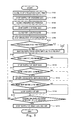
- FIG. 5 is a flowchart showing a stop operation of the fuel cell system according to the embodiment 1 of the present invention.
- FIG. 6 is a flowchart showing a start-up operation of the fuel cell system according to the embodiment 1 of the present invention.
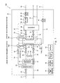
- FIG. 7 is a block diagram showing an example of a schematic configuration of a hardware of a fuel cell system according to an embodiment 2 of the present invention.
- FIG. 8 is a block diagram showing an example of a schematic configuration of a hardware of a fuel cell system according to an embodiment 3 of the present invention.
- FIG. 9 is a block diagram showing an example of a schematic configuration of a hardware of a fuel cell system according to an embodiment 4 of the present invention.
- FIG. 10 is a block diagram showing an example of a schematic configuration of a hardware of a fuel cell system according to an embodiment 5 of the present invention.
- FIG. 11 is a block diagram showing an example of a schematic configuration of a hardware of a fuel cell system according to an embodiment 6 of the present invention.
- FIG. 12 is a flowchart showing a stop operation of the fuel cell system according to the embodiment 6 of the present invention.
- the temperature of the fuel cell gradually decreases.
- cross leak of reaction gases via a polymer electrolyte membrane occurs.
- hydrogen in an anode space and oxygen in a cathode space react with each other and are consumed, generating water. Also, hydrogen and oxygen are sometimes consumed due to self-discharge, etc. Because of the temperature decrease and the consumption of the reaction gases, the pressure in the interior of the fuel cell decreases.
- the anode space basically contains plenty of hydrogen and is in a reduction atmosphere.
- An inert gas which is incapable of decreasing the electrode potential, is supplied to reduce a pressure difference between the anode space and an outside space, thereby obviating a risk that oxygen in air enters and increase the potential.
- the cathode side is basically in an oxidization atmosphere because of the presence of oxygen derived from air. If the cathode space is isolated from an outside space, oxygen remaining within the cathode space reacts with hydrogen derived from the anode to generate water, so that a gas other than oxygen, such as nitrogen, remains there. Air contains as major components oxygen and nitrogen.
- the electrode potential can be surely decreased and thereby degradation of the electrodes is prevented.
- a special cylinder or the like for purging the cathode space with the inert gas may be omitted, and thus a configuration can be simplified. Since the gas with the amount for making up for the pressure decrease is supplied both to the anode space and to the cathode space, there is not generated a pressure difference between these spaces and atmosphere, so that an amount of entry of oxygen can be minimized. By preventing the pressure decrease, damage to the polymer electrolyte membrane or electrical short between the electrodes can be prevented.
- a reducing agent e.g., hydrogen
- an oxidizing agent e.g., oxygen
- a simple way to make hydrogen more in amount than oxygen is to make the anode space larger in volume than the cathode space.
- the ratio between the volumes varies depending on the temperature or composition of the gases supplied to the anode and to the cathode (including a partial pressure of steam), the temperature in a power generation state or in an operation stop state, etc.
- the volumes can be calculated according to the following formulae. In the calculation below, it is assumed that gases comply with ideal gas equations, for the sake of simplicity.
- the volume decreases as the temperature decreases under the condition in which the amount of substances and the pressure are constant. If the gases are consumed through the reaction, the volume decreases.
- the temperature of the fuel cell decreases and the fuel cell is in a stable state (operation stop state). It is assumed that the temperature of the interior of the fuel cell in the operation stop state is a room temperature (e.g., 25° C.).
- the oxidizing gas gas supplied to the cathode: air
- the oxidizing gas is humidified up to a saturated water vapor pressure during the operation.
- n 25 c 25 ⁇ (1 ⁇ PW 25 )
- the gases (anode gases) in the anode space in the operation state mainly includes hydrogen, steam, and carbon dioxide.
- PW 25 , PN, and PO are constants.
- an actually measured value can be used as a constant. Therefore, by compensating for the temperature difference between a 70 and c 25 , a volume ratio between the anode space and the cathode space is obtained.
- the volume (theoretical value) of the anode space is substantially equal to the volume of the cathode space. If hydrogen is more in amount, then the electrode potential is less likely to increase. As the size of the anode space increases, the size of the fuel cell system increases, hydrogen which will be wastefully consumed becomes necessary. Considering an actual reaction speed, a speed of cross leak in the polymer electrolyte membrane, a ratio of gasses which are not consumed in the reaction, etc, the volume of the anode space is suitably not smaller than the volume of the cathode space and not larger than three times as large as the volume of the cathode space, in actuality.
- the electrode potential can be surely maintained to be lower than +0.88V during the state where the fuel cell system is not generating the electric power. Thereby, degradation of the electrodes can be prevented, and as a result, life of the electrodes can be improved. Also, with such a configuration, it is expected that degradation of the electrodes is prevented even when a stop period continues about one month. Inflow and outflow of leaking air and leaking hydrogen are nonnegligible depending on a capability of closing devices (e.g., closing valves). In that case, it is desirable to further increase the volume of the anode space to increase the amount of hydrogen. Based on experience, it is desired that the volume of the anode space be larger than the volume of the cathode space.
- the volume of the anode space is preferably not smaller than the volume of the cathode space and not larger than three times as large as the volume of the cathode space. More preferably, the volume of the anode space is not smaller than 1.5 times as large as the volume of the cathode space and not larger than three times as large as the volume of the cathode space.
- FIG. 1 is a view showing an example of a schematic configuration of the internal structure of the polymer electrolyte fuel cell according to the embodiment 1 of the present invention. As shown in FIG. 1
- the polymer electrolyte fuel cell includes a polymer electrolyte membrane 11 , a catalyst layer 12 a , a catalyst layer 12 c , a gas diffusion layer 13 a , a gas diffusion layer 13 c , an electrically-conductive separator 16 a , an electrically-conductive separator 16 c , a MEA gasket 17 a , a MEA gasket 17 c , and a separator gasket 18 .
- the catalyst layer 12 a and the catalyst layer 12 c are respectively disposed in close contact with both surfaces of the polymer electrolyte membrane 11 .
- the gas diffusion layer 13 a and the gas diffusion layer 13 c have gas permeability and electrical conductivity and are respectively disposed in close contact with outer surfaces (surfaces on the opposite side of the polymer electrolyte membrane 11 ) of the catalyst later 12 a and the catalyst layer 12 c .
- the gas diffusion layer 13 a and the catalyst layer 12 a form an electrode (anode) 14 a
- the gas diffusion layer 13 c and the catalyst layer 12 c form an electrode (cathode) 14 c.
- the electrode 14 a , the electrode 14 c , and the polymer electrolyte membrane 11 form an MEA (membrane electrode assembly) 15 .
- the MEA 15 is sandwiched between the pair of electrically-conductive separator 16 a and electrically-conductive separator 16 c .
- the electrically-conductive separator 16 a and the electrically-conductive separator 16 c serve to mechanically fasten the MEA 15 , and to electrically connect adjacent MEAs 15 in series.
- the MEA 15 and the electrically-conductive separator 16 a are sealed by the MEA gasket 17 a
- the MEA 15 and the electrically-conductive separator 16 c are sealed by the MEA gasket 17 c
- the electrically-conductive separator 16 a and the electrically-conductive separator 16 c are adapted to be in contact with the electrically-conductive separator 16 c and the electrically-conductive separator 16 a of associated adjacent cells 19 on their surfaces which are on the opposite side of the MEA 15 .
- the electrically-conductive separator 16 a and the electrically-conductive separator 16 c are sealed by the separator gasket 18 .
- An anode gas passage 20 a and a cathode gas passage 20 c are formed on the surface of the electrically-conductive separator 16 a which is in contact with the MEA 15 and the surface of the electrically-conductive separator 16 c which is in contact with the MEA 15 , respectively, to supply reaction gases to the electrodes and to carry away the gases generated through the reaction and surplus gases.
- Gas inlets of the anode gas passages 20 a are respectively connected to anode-side supply manifolds which are not shown.
- Gas outlets of the anode gas passages 20 a are respectively connected to anode-side discharge manifolds which are not shown.
- the anode-side supply manifolds, the anode gas passages 20 a , and the anode-side discharge manifolds form an anode-side gas passage 97 which is one passage in the interior of the fuel cell.
- Gas inlets of the cathode gas passages 20 c are respectively connected to cathode-side supply manifolds which are not shown.
- Gas outlets of the cathode gas passages 20 c are respectively connected to cathode-side discharge manifolds which are not shown.
- the cathode-side supply manifolds, the cathode gas passages 20 c , and the cathode-side discharge manifolds form a cathode-side gas passage 98 which is one passage in the interior of the fuel cell.
- a cooling water passage 21 is formed on each of the electrically-conductive separator 16 a and the electrically-conductive separator 16 c to be located at an interface between adjacent cells 19 . Cooling water is flowed in the cooling water passage 21 . The cooling water removes heat generated in the MEA 15 , via the electrically-conductive separator 16 a and the electrically-conductive separator 16 c.
- the cell 19 is preferably manufactured as follows. Carbon powder comprised of acetylene black (Denka Black produced by Denki Kagaku Co. Ltd, particle diameter of 35 nm) is mixed with an aqueous dispersion (D1 produced by DAIKIN INDUSTRIES, Ltd.) of polytetrafluoroethylene (PTFE) to produce a water-repellent ink containing 20 wt % of PTFE as a dry weight. The ink is applied onto and impregnated in a carbon paper (TGPHO60H produced by TORAY Co. Ltd) which is a base material of the gas diffusion layer. The carbon paper impregnated with the ink is subjected to thermal treatment at 300° C. using a hot air drier to produce the gas diffusion layer 13 a and the gas diffusion layer 13 c (about 200 ⁇ m).
- acetylene black Diska Black produced by Denki Kagaku Co. Ltd, particle diameter of 35 nm
- D1 aqueous dispersion
- a catalyst body 50 wt % is Pt
- Ketjen Black Ketjen Black EC, particle diameter of 30 nm manufactured by Ketjen Black International Co., Ltd
- 33 wt part (polymer dry weight) of perfluorosulfonic acid ionomer 5 wt % of Nafion dispersion liquid manufactured by Aldrich Co Ltd. in US
- the resulting mixture is molded to form the catalyst layer 12 a and the catalyst layer 12 c (10 to 20 ⁇ m).
- the gas diffusion layers 13 a and 13 c and the catalyst layers 12 a and 12 c which have been produced as described above are joined to the both surfaces of the polymer electrolyte membrane 11 (Nafion 112 membrane manufactured by Dupont Co. Ltd. in US), thus manufacturing the MEA 15 .
- rubber-made gasket plates (MEA gasket 17 a and MEA gasket 17 c ) are joined to outer peripheral regions of the polymer electrolyte membrane 11 of the MEA 15 manufactured as described above, to form manifold holes for the cooling water, the fuel gas, and the oxidizing gas to flow therethrough.
- the electrically-conductive separators 16 a and 16 c are formed of graphite plates each of which has an outside dimension of (20 cm ⁇ 32 cm ⁇ 1.3 mm), is impregnated with phenol resin and is provided with a groove-like gas passage and a groove-like cooling water passage having a depth of 0.5 mm.
- the separator gasket 18 is made of, for example, at least one material selectable from a group consisting of fluorocarbon rubber, polyisoprene, butyl rubber, ethylene-propylene rubber, silicone rubber, nitrile rubber, thermoplastic elastomer, liquid crystal polymer, polyimide resin, polyether ether ketone resin, polyetherimide resin, polyphenylene sulfide resin, terephthalamido resin, polyethersulfonic resin, polysulfonic resin, sybdiotactic polystyrene resin polymethyl pentene resin, denaturation polyphenyleneether resin, polyacetal resin, polypropylene resin, fluorocarbon resin, and polyethylene telephthalete resin (including a composite material containing two or more kinds of these materials). In view of durability, fluorocarbon rubber is preferable.
- the MEA 15 , the electrically-conductive separator 16 a and the electrically-conductive separator 16 c , and the separator gasket 18 are stacked to manufacture the cell 19 .
- FIG. 2 is a perspective view schematically showing a structure of a fuel cell (stack) formed by stacking cells.
- a fuel cell 30 includes a plurality of stacked cells 19 , a pair of current collecting plate 31 a and current collecting plate 31 c , a pair of insulating plates 32 , and a pair of end plates 33 .
- the voltage per cell is typically as low as +0.75V. Therefore, in the fuel cell 30 , the plurality of cells 19 are stacked in series to be able to achieve a high voltage.
- An electric current is taken out from the fuel cell 30 through the current collecting plates 31 a and 31 c .
- the insulating plates 32 serve to electrically insulate the cells 19 from outside.
- the end plates 33 serve to fasten and mechanically retain the fuel cell 30 including the stacked cells 19 .
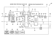
- FIG. 3 is a block diagram showing an example of a schematic configuration of the hardware of the fuel cell system according to the embodiment 1 of the present invention.
- a fuel cell system 40 of the present embodiment includes as major components, the fuel cell 30 , a gas purifier 41 , a hydrogen generator 42 , a burner 43 , a blower 44 , a filter 45 , a humidifier 46 , a pump 47 , an outer casing 48 , a controller 49 , and an input/output device 50 .
- the burner 43 is disposed to be able to supply combustion heat to the hydrogen generator 42 .
- a gas inlet of the gas purifier 41 is coupled through an unpurified material gas supply pipe 51 to a gas main tap which is not shown.
- An on-off valve 52 is provided in the unpurified material gas supply pipe 51 to open and close a passage of the unpurified material gas supply pipe 51 .
- a gas outlet of the gas purifier 41 is coupled to a gas inlet of the hydrogen generator 42 through a purified material gas supply pipe 53 .
- a start end of a purified material gas bypass pipe 54 is coupled to the purified material gas supply pipe 53 .
- a gas outlet of the hydrogen generator 42 is coupled to an anode-side gas inlet of the fuel cell 30 through a fuel gas supply pipe 55 .
- An on-off valve (first on-off valve) 56 is provided in the fuel gas supply pipe 55 to open and close a passage of the fuel gas supply pipe 55 .
- a start end of the fuel gas bypass pipe 57 is coupled to the fuel gas supply pipe 55 in a location between the hydrogen generator 42 and the on-off valve 56
- a terminal end of the purified material gas bypass pipe 54 is coupled to the fuel gas supply pipe 55 in a location between the on-off valve 56 and the fuel cell 30 .
- An on-off valve (fifth on-off valve) 58 is provided in the purified material gas bypass pipe 54 to open and close a passage of the purified material gas bypass pipe 54 .
- An anode space pressure detector 59 a is attached on the fuel gas supply pipe 55 in a location between a portion of the fuel gas supply pipe 55 connected to the purified material gas bypass pipe 54 and the fuel cell 30 to detect a pressure in the interior of the passage.
- An anode-side gas outlet of the fuel cell 30 is coupled to a gas inlet of the burner 43 through an off gas pipe 60 .
- An on-off valve (second on-off valve) 61 is provided in the off gas pipe 60 to open and close a passage of the off gas pipe 60 .
- a terminal end of the fuel gas bypass pipe 57 is coupled to the off gas pipe 60 in a location between the on-off valve 61 and the burner 43 .
- the fuel gas bypass pipe 57 connects the fuel gas supply pipe 55 to the off gas pipe 60 so as to bypass the fuel cell 30 .
- An on-off valve 62 is provided in the fuel gas bypass pipe 57 to open and close a passage of the fuel gas bypass pipe 57 .
- a combustion exhaust gas discharge pipe 63 is coupled to a gas outlet of the burner 43 to be able to discharge an exhaust gas from the burner 43 to outside the fuel cell system.
- the unpurified material gas supply pipe 51 , the purified material gas supply pipe 53 , the fuel gas supply pipe 55 , the anode-side gas passage 97 , the off gas pipe 60 , and the combustion exhaust gas discharge pipe 63 form a fuel gas passage in the present embodiment.
- the purified material gas bypass pipe 54 and the on-off valve 58 constitute an inert gas supply device in the present embodiment.
- An anode space 111 in the present embodiment is defined by passages which are substantially isolated (sealed) from outside by closing the on-off valve 56 , the on-off valve 61 , and the on-off valve 58 (closing devices), to be specific, the interior of a portion of the fuel gas supply pipe 55 which extends from the on-off valve 56 to the anode-side gas inlet of the fuel cell 30 , the interior of a portion of the purified material gas bypass pipe 54 which extends from the on-off valve 58 to the fuel gas supply pipe 55 , the anode-side gas passage 97 , the interior of a portion of the off-gas pipe 60 which extends from the anode-side gas outlet of the fuel cell 30 to the on-off valve 61 , and the interior of a pipe coupling the anode space pressure detector 59 a to the fuel gas supply pipe 55 (part indicated by double lines in FIG. 3 ).
- An oxidizing gas intake pipe 64 is coupled to a gas inlet of the blower 44 so that the blower 44 can take in air from outside.
- a gas outlet of the blower 44 is coupled to a gas inlet of a filter 45 through an unpurified oxidizing gas supply pipe 65 .
- a gas outlet of the filter 45 is coupled to an oxidizing gas inlet of the humidifier 46 through a purified oxidizing gas supply pipe 66 .
- a start end of the purified oxidizing gas bypass pipe 67 is coupled to the purified oxidizing gas supply pipe 66 .
- a cathode-side gas inlet of the fuel cell 30 is coupled to an oxidizing gas outlet of the humidifier 46 through a humidified oxidizing gas supply pipe 68 .
- An on-off valve (third on-off valve) 69 is provided in the humidified oxidizing gas supply pipe 68 to open and close a passage of the humidified oxidizing gas supply pipe 68 .
- a terminal end of the purified oxidizing gas bypass pipe 67 is coupled to the humidified oxidizing gas supply pipe 68 in a location between the on-off valve 69 and the fuel cell 30 , and a cathode space pressure detector 59 c is attached on the humidified oxidizing gas supply pipe 68 in a location between the fuel cell 30 and a connecting portion of the purified oxidizing gas bypass pipe 67 connected to the humidified oxidizing gas supply pipe 68 to detect a pressure in the interior of the passage.
- An on-off valve (sixth on-off valve) 70 is provided in the purified oxidizing gas bypass pipe 67 to open and close a passage of the purified oxidizing gas bypass pipe 67 .
- a cathode-side gas outlet of the fuel cell 30 is coupled to an exhaust oxidizing gas inlet of the humidifier 46 through an oxidizing gas discharge pipe 71 .
- An on-off valve (fourth on-off valve) 72 is provided in the oxidizing gas discharge pipe 71 to open and close a passage of the oxidizing gas discharge pipe 71 .
- An exhaust oxidizing gas discharge pipe 73 is coupled to an exhaust oxidizing gas outlet of the humidifier 46 to be able to discharge the exhaust oxidizing gas discharged from the humidifier to outside the system.
- the oxidizing gas intake pipe 64 , the unpurified oxidizing gas supply pipe 65 , the purified oxidizing gas supply pipe 66 , the humidified oxidizing gas supply pipe 68 , the cathode-side gas passage 98 , the oxidizing gas discharge pipe 71 , and the exhaust oxidizing gas discharge pipe 73 form an oxidizing gas passage of the present embodiment.
- the purified oxidizing gas bypass pipe 67 and the on-off valve 70 constitute an air supply device of the present embodiment.
- a cathode space 112 in the present embodiment is defined by passages which are substantially isolated (sealed) from outside by closing the on-off valve 69 , the on-off valve 72 , and the on-off valve 70 (closing devices), to be specific, the interior of a portion of the humidified oxidizing gas supply pipe 68 which extends from the on-off valve 69 to the cathode-side gas inlet of the fuel cell 30 , the interior of a portion of the purified oxidizing gas bypass pipe 67 which extends from the on-off valve 70 to the humidified oxidizing gas supply pipe 68 , the cathode-side gas passage 98 , the interior of a portion of the oxidizing gas discharge pipe 71 which extends from the cathode-side gas outlet of the fuel cell 30 to the on-off valve 72 , the interior of a pipe coupling the cathode space pressure detector 59 c to the humidified oxidizing gas supply pipe 68 (part indicated by a double line in FIG. 3
- a first method is as follows.
- a first gas e.g., nitrogen
- a second gas e.g., hydrogen
- Time taken for the second gas to flow out from the anode space and time taken for the second gas to flow out from the cathode space are measured and thereby the size of the anode space and the size of the cathode space are compared.
- a second method is as follows.
- a third method is as follows. A portion corresponding to the anode space or the cathode space is disassembled from the system and water is filled into the anode space and the cathode space. The volume of the anode space and the volume of the cathode space are measured, for example, 1) by measuring the amount of water filled thereinto, 2) by measuring the amount of water flowing out therefrom, or 3) by measuring increases in weights of the portion.
- a cooling water inlet of a pump 47 is coupled through a cooling water intake pipe 74 to a cooling water outlet of a hot water storing tank which is not shown.
- a cooling water outlet of the pump 47 is coupled to a cooling water inlet of the fuel cell 30 through a cooling water supply pipe 75 .
- a cooling water outlet of the fuel cell 30 is coupled to a cooling water inlet of the humidifier 46 through a cooling water discharge pipe 76 .
- a cooling water outlet of the humidifier 46 is coupled through a cooling water re-supply pipe 77 to a cooling water inlet of the hot water storing tank which is not shown.
- a hydrocarbon based gas such as a natural gas or a propane gas
- a city gas 13A which is a mixture gas of methane, ethane, propane, and butane may be used.
- air is used as the oxidizing gas, but any mixture gas may be used so long as it is a mixture of the oxidizing agent and the inert gas.
- a gas odorant such as TBM (tertiary butyl mercaptan), DMS (dimethyl sulfide), or THT (tetrahydrotiophene) is used.
- the humidifier 46 means for flowing the oxidizing gas in hot water, means for blowing water into the oxidizing gas, etc may be used.
- a total enthalpy heat exchange type humidifier is adapted to transfer water and heat from the exhaust gas to the oxidizing gas supplied from the oxidizing gas intake pipe 64 and thereafter to transfer water and heat from the cooling water to the oxidizing gas when the exhaust gas and the cooling water pass through the humidifier 46 .
- any valves may be used so long as they are able to close the passages of the associated pipes.
- an electromagnetic valve, a power-driven ball valve, etc may be used.
- any detectors may be used so long as they are able to detect the pressures of gases in the passages inside the associated pipes.
- pressure sensors using diaphragm may be used.
- the inert gas the material gas which has been purified by the gas purifier 41 may be used.
- the material gas contains, as a major component, the methane gas, it does not substantially have a reactivity to the polymer electrolyte fuel cell used in the present embodiment, and therefore may be used as the inert gas.
- the inert gas is not necessarily the material gas, and any gases may be used so long as they do not cause electrode reaction (do not contribute to oxidization and reduction reactions of the electrodes) do not degrade the electrodes, and are chemically stable, in the interior of the fuel cell in a stop state.
- the inert gas the city gas such as 13A, natural gas, methane gas, ethane gas, propane gas, butane gas, nitrogen, argon may be used.
- a cylinder is preferably equipped. Hydrogen gas is incapable of being used as the inert gas.
- a gas which has been purified by removing odorants (S component) which are impurities contained in the city gas is used as the inert gas. It should be noted that the removal of the impurities is performed to prevent poisoning of Pt contained in the catalyst layer.
- FIG. 4 is a block diagram showing a schematic configuration of the control system of the fuel cell system according to the embodiment 1 of the present invention.
- the control system of the fuel cell system of the present embodiment comprises a controller 49 including a control unit 80 , a memory 81 , and a timer 82 .
- the control unit 80 is configured to receive signals from the timer 82 and the input/output device 50 and to store calculation results or the like in the memory 81 as desired.
- the control unit 80 is configured to receive detection signals from a temperature detector (not shown) attached on the hydrogen generator 42 , the anode space pressure detector 59 a , the cathode space pressure detector 59 c , and a voltage measuring unit 96 and to control the operations of the burner 43 , the on-off valve 52 , the on-off valve 56 , the on-off valve 58 , the on-off valve 61 , the on-off valve 62 , the on-off valve 69 , the on-off valve 70 , the on-off valve 72 , the blower 44 , the pump 47 , and the electric power circuit unit 95 , based on programs stored in the memory 81 and parameter values received from the input/output device 50 .
- control unit 80 for example, a CPU is used.
- memory 81 for example, an internal memory is used.
- timer 82 for example, a clock circuit with a calendar is used.
- one controller 49 and one control unit 80 are equipped to be able to execute centralized control, but a plurality of controllers 49 and control units 80 may be equipped to be able to execute distributed control.
- the material gas is taken in from outside through the unpurified material gas supply pipe 51 , and is purified in the gas purifier 41 for removing substances which negatively affect the fuel cell. Thereafter, the gas is guided to the hydrogen generator 42 through the purified material gas supply pipe 53 .
- the material gas is pressurized in the main gas tap and is supplied.
- the flow rate of the material gas is controlled by a needle valve (or booster pump, etc) which is not shown and is provided in the unpurified material gas supply pipe 51 in a location between the on-off valve 52 and the gas purifier 41 .
- the hydrogen generator 42 generates the fuel gas containing at least hydrogen from the material gas through a steam-reforming reaction.
- the fuel gas is guided from the hydrogen generator 42 to the anode side of the fuel cell 30 through the fuel gas supply pipe 55 .
- hydrogen is generated through a reaction or the like indicated by (chemical formula 6). Carbon monoxide generated concurrently with hydrogen is removed to reach 10 ppm or less through a shift reaction indicated by (chemical formula 7) and a carbon monoxide selective oxidization reaction indicated by (chemical formula 8).
- a reaction for generating the fuel gas from the material gas is an endothermic reaction as indicated by (chemical formula 6). Combustion heat generated in the burner 43 is used as heat required for the reaction.
- the fuel gas which has passed through the fuel cell 30 , is guided to the burner 43 through the off gas pipe 60 and combusted therein.
- An exhaust gas from the burner 43 is discharged outside the fuel cell system through the combustion exhaust gas discharge pipe 63 .
- the controller 49 closes the on-off valve 56 , and the on-off valve 61 , and opens the on-off valve 62 provided in the fuel gas bypass pipe 57 . Under such control, the fuel gas is guided to the off gas pipe 60 so as to bypass the fuel cell 30 and is combusted in the burner 43 .
- the combustion heat from the burner 43 is used to increase the temperature of the hydrogen generator 42 , an endothermic reaction for generating the fuel gas from the material gas, etc.
- the oxidizing gas (air) is taken into the blower 44 from outside through the oxidizing gas intake pipe 64 , is pressurized therein, and is supplied to the filter 45 . After the impurities are removed from the oxidizing gas in the filter 45 , the oxidizing gas is humidified in the humidifier 46 to take in moisture necessary for the fuel cell and is guided to the cathode side of the fuel cell 30 through the humidified oxidizing gas supply pipe 68 .
- the exhaust oxidizing gas discharged from the fuel cell 30 is guided to the humidifier 46 through the oxidizing gas discharge pipe 71 .
- the exhaust oxidizing gas has high-temperature and contains plenty of moisture.
- the exhaust oxidizing gas supplies water and heat to the oxidizing gas in the humidifier 46 .
- the exhaust oxidizing gas discharged from the humidifier 46 is discharged outside the fuel cell system through the exhaust oxidizing gas discharge pipe 73 .
- the pump 47 takes in the cooling water from the hot water storing tank through the cooling water intake pipe 74 .
- the cooling water is supplied to the fuel cell 30 through the cooling water supply pipe 75 .
- the cooling water discharged from the fuel cell 30 is supplied to the humidifier 46 through the cooling water discharge pipe 76 .
- the cooling water discharged from the fuel cell 30 has a high temperature.
- the cooling water supplies moisture and heat to the oxidizing gas in the humidifier 46 .
- the cooling water discharged from the humidifier 46 is returned to the hot water storing tank through the cooling water re-supply pipe 77 .
- the flow of the cooling water in the fuel cell 30 of the fuel cell allows the fuel cell 30 generating heat to be kept at a constant temperature.
- the heat generated in the fuel cell 30 of the fuel cell is stored in the hot water storing tank and used for supplying hot water, etc.
- the temperature of the fuel cell 30 is 70° C.
- fuel gas utilization rate (Uf) is 75%
- oxygen utilization rate (Uo) is 50%.
- the fuel gas and the air are humidified to have a dew point of 66° C. and a dew point of 66° C., respectively.
- An electric current having a certain voltage is taken out as an electric power from the electric power circuit unit 95 .
- the electric current is controlled to have a current density of 0.2 A/cm 2 with respect to an apparent area of the electrode.
- the operation of the pump 47 is controlled so that the temperature of water in the cooling water intake pipe 74 is 60° C. and the temperature of water in the cooling water re-supply pipe 77 is 68° C.
- the electric power and heat are generated using the fuel gas supplied to the anode side and the oxidizing gas supplied to the cathode side.
- the controller 49 determines the amount of electric power to be supplied from an electric power system and the amount of electric power (target value of electric power generated in power generation) generated in and supplied from the fuel cell 30 .
- the controller 49 sends to the devices such as the pump and the blower so that the electric power generated in power generation changes at a constant speed (rate: e.g., 1 W/second) to reach the target value of electric power generated in power generation.
- the voltage of the fuel cell 30 is monitored in the voltage measuring unit 96 .
- a command is sent to the devices so that changing of the electric power generated in power generation is stopped.
- the electric power circuit unit 95 converts a DC electric power taken out from the fuel cell 30 into an AC electric power, and is connected to an electric power line used at home, etc by so-called power system interconnection.
- Oxygen-containing gas such as air is flowed in the cathode gas passage 20 c , while the fuel gas containing hydrogen is flowed in the anode gas passage 20 a .
- Hydrogen in the fuel gas diffuses in the gas diffusion layer 13 a and reaches the catalyst layer 12 a .
- the catalyst layer 12 a hydrogen is separated into hydrogen ions and electrons. The electrons are migrated to the cathode side through an external circuit.
- the hydrogen ions migrate to the cathode side through the polymer electrolyte membrane 11 , and reach the catalyst layer 12 c .
- oxygen reacts with electrons and is converted into oxygen ions which further react with hydrogen ions to generate water.
- the oxygen-containing gas and the fuel gas react with each other in the MEA 15 and in its vicinity, thereby generating water, and an electromotive force is generated between the catalyst layer 12 a and the catalyst layer 12 c .
- heat as well as water is generated, causing the temperature of the MEA 15 to rise. The generated heat is carried away outside the fuel cell 30 by the cooling water flowing in the cooling water passage 21 .
- the fuel cell of the present embodiment is configured to cause the gas diffusion electrodes to electrically react the fuel gas containing at least hydrogen and the oxidizing gas containing oxygen such as air to generate electricity and heat simultaneously.
- the reactions indicated by (chemical formula 9) and (chemical formula 10) occur in the catalyst layer 12 a and the catalyst layer 12 c , respectively, and the reaction indicated by (chemical formula 11) occurs in the entire fuel cell.
- H 2 ⁇ 2H + +2 e ⁇ (chemical formula 9) 1 ⁇ 2O 2 +2H + +2 e ⁇ ⁇ H 2 O (chemical formula 10)
- the fuel gas containing at least hydrogen causes the reaction (hereinafter referred to as an anode reaction) indicated by (chemical formula 9).
- the hydrogen ions which have migrated through the polymer electrolyte membrane 11 , causes the reaction (hereinafter referred to as a cathode reaction) indicated by (chemical formula 10) with the oxidizing gas in the catalyst layer 12 c to generate water while generating electricity and heat.
- the side associated with the fuel gas such as hydrogen is the anode side (region indicated by a in the drawing) and the side associated with the oxidizing gas such as air is the cathode side (region indicated by c in the drawing).
- the polymer electrolyte membrane 11 has the fixed electric charge, and the hydrogen ions are present as counter ions of the fixed electric charge.
- the polymer electrolyte membrane 11 is required to be able to cause the hydrogen ions to selectively permeate therethrough.
- the polymer electrolyte membrane 11 is required to retain moisture. This is because, the moisture contained in the polymer electrolyte membrane 11 makes it possible that the fixed electric charge fixed within the polymer electrolyte membrane 11 are ionized, and hydrogen which are the counter ions of the fixed electric charge are ionized and migrate.
- FIG. 5 is a flowchart showing a stop operation of the fuel cell system according to the embodiment 1 of the present invention.
- the stop operation of the fuel cell system of the present invention will be described with reference to FIG. 5 .
- the controller 49 detects this, and determines whether the power generation in the fuel cell 30 should be continued or the power generation in the fuel cell 10 is stopped and all of the requested electric power should be supplied from external equipment (system). If it is determined that the power generation in the fuel cell 30 should be continued, the controller 49 sends a command to the devices such as the pump and the blower so that the electric power to be generated changes (increases or decreases) with a constant change rate up to a target value which is a desired electric power generated in the power generation. On the other hand, if it is determined that the power generation in the fuel cell 30 should be stopped, the controller 49 starts the stop operation (start). When the stop operation is started, a first stop step is initially performed.
- the controller 49 receives a current time from the timer 82 and stores it as a stop operation start time (step S 10 ).
- the supply of the oxidizing gas from the blower is stopped (step S 102 ), and the on-off valve 69 and the on-off valve 72 are closed to close the oxidizing gas passage (step S 103 ).
- the on-off valve 70 is closed and is closed at the time of step 103 .
- the cathode space 112 is isolated from outside.
- the supply of the fuel gas from the hydrogen generator 42 is stopped (step S 104 ).
- the on-off valve 56 and the on-off valve 61 are closed, and the fuel gas passage is closed (step S 105 ).
- the on-off valve 58 is closed and is closed at the time of step S 105 .
- the anode space 111 is isolated from outside and the power generation is stopped (i.e., taking out an electric current is stopped).
- circulation of the cooling water is stopped (step S 106 ).
- the potential of the anode and the potential of the cathode in the stop state be maintained at about ⁇ 0V (vs.
- the SHE by stopping the operation of the fuel cell 30 under the condition where the fuel cell contains least possible oxygen, and that the cathode and the anode be tightly closed in this order.
- it is a waste of the material gas if it is used during a state where the fuel cell system is not generating the electric power (electric current is not taken out from the fuel cell 30 ). For this reason, it is most desirable that the cathode and the anode be tightly closed in the above described order substantially simultaneously.
- the first stop step is terminated. After the first stop step is terminated, a second stop step is performed.
- a second stop step the supply of the fuel gas and the supply of the oxidizing gas are in a stopped state, the temperature of the fuel cell 30 decreases, and the pressure in the anode space 111 and the pressure in the cathode space 112 decrease.
- the main cause of the pressure decrease is that cross leak via the polymer electrolyte membrane 11 occurs and causes hydrogen and oxygen to be consumed through the reaction, and steam is condensed due to temperature decrease.
- the controller 49 causes the anode space pressure detector 59 a to detect the pressure (anode space pressure) in the anode space 111 , and causes the cathode space pressure detector 59 c to detect the pressure (cathode space pressure) in the cathode space 112 .
- step S 1107 it is determined whether or not the anode space pressure is lower than a first pressure. If it is determined YES in step S 107 , the on-off valve 58 is opened. At this time, the on-off valve 52 is fully opened, and the needle valve (not shown) which is provided in the unpurified material gas supply pipe 51 in the location between the on-off valve 52 and the gas purifier 41 is fully opened as well (the pump is in a stopped state and is fully opened in a case where the booster pump or the like is used instead of the needle valve).
- the material gas (inert gas), which has been purified in the gas purifier 41 is supplied to the anode space 111 through the purified material gas bypass pipe 54 (step S 108 ), and it is determined whether or not to stop supply of the inert gas. If it is determined NO in step S 107 , then it is determined whether or not to stop the supply of the inert gas.
- the first pressure is set to a value which is 5 kPa lower than an ambient pressure.
- the ambient pressure may be an atmospheric pressure around the fuel cell system which is detected by an ambient pressure detector (not shown).
- 101.3 kPa one atmosphere: standard atmospheric pressure
- the reason why the first pressure is set to the value which is 5 kPa lower than the ambient pressure is that an operation pressure of an actual low-pressure loss type fuel cell system is commonly not higher than a value in a range of 5 to 10 kPa, and a burden placed on a sealing part can be reduced by eliminating a negative pressure with a pressure lower than the operation pressure.
- the first pressure may be lower in order to reduce the number of times the on-off valve 58 is opened and closed. In this case, a value which is 20 kPa lower than the ambient pressure is a lower limit value in view of a general proof pressure of the sealing part.
- the anode space pressure detector 59 a may be configured to detect a difference pressure (negative pressure) between the ambient pressure and the anode space pressure. In such a configuration, the on-off valve 58 is controlled based on comparison between the negative pressure and the first pressure, and thereby substantially similar effects can be achieved.
- the first pressure may be decided based on the supply pressure of the material gas as a reference, rather than the ambient pressure. For example, the first pressure may be set to a value which is 5 kPa lower than the supply pressure of the material gas.
- step S 109 it is determined whether or not the anode space pressure is not lower than the ambient pressure. If it is determined YES in step S 109 , the on-off valve 58 is closed and the supply of the material gas (inert gas) is stopped (step S 10 ). After the step S 110 , determination as to the cathode space pressure is performed. If it is determined NO in step S 109 , then determination as to the cathode space pressure is performed.
- step S 11 it is determined whether or not the cathode space pressure is lower than a second pressure (step S 11 ). If it is determined YES in step S 111 , the on-off valve 70 is opened and the oxidizing gas (air) which has been purified in the filter 45 is supplied to the cathode space 112 through the purified oxidizing gas bypass pipe 67 (step S 112 ), and it is determined whether or not to stop air supply. If it determined NO in step S 111 , then it is determined whether or not stop air supply. In step S 112 , the blower 44 is in a stopped state, but the amount of air to be supplied is small. So, the air flows into the cathode space 112 through a clearance of a scroll of the blower 44 .
- the second pressure is set to a value which is 5 kPa lower than an ambient pressure.
- the ambient pressure may be an atmospheric pressure around the fuel cell system which is detected by an ambient pressure detector (not shown).
- 101.3 kPa one atmosphere
- the reason why the second pressure is set to a value which is 5 kPa lower than the ambient pressure is that the operation pressure of the actual low-pressure loss type fuel cell system is commonly not higher than a value in a range of 5 to 10 kPa, and a burden placed on the sealing part can be reduced by eliminating a negative pressure with a pressure lower than the operation pressure.
- the second pressure may be lower in order to reduce the number of times the on-off valve 70 is opened and closed.
- a value which is 20 kPa lower than the ambient pressure is a lower limit value in view of the general proof pressure of the sealing part.
- the cathode space pressure detector 59 c may be configured to detect a difference pressure (negative pressure) between the ambient pressure and the cathode space pressure.
- the on-off valve 70 is controlled based on comparison between the negative pressure and the second pressure, and thereby substantially similar effects can be achieved.
- the first pressure and the second pressure may be equal to each other or different from each other.
- step S 113 it is determined whether or not the cathode space pressure is not lower than the ambient pressure. If it is determined YES in step s 113 , the on-off valve 70 is closed, and supply of the air is stopped (step S 114 ). After step S 114 , it is determined whether or not to stop the operation. If it is determined NO in step S 114 , then it is determined whether or not to stop supply of the inert gas and supply of air.
- step S 115 it is determined whether or not a specified time period has lapsed after start of the stop operation.
- the time period is calculated using the stop operation start time stored in step S 101 and the current time received from the timer 82 . If the time period is longer than a specified time period (e.g., one hour), the supply of the inert gas and the supply of the air are stopped (step S 116 ), and the fuel cell system enters a stand-by state (end). On the other hand, if the time period is not longer the specified time period, the process returns to step S 107 .
- a specified time period e.g., one hour
- the second stop step if the pressure in the interior of the fuel cell 30 becomes a predetermined value or less, gas supply is repeatedly performed. As a result of such an operation, a concentration of hydrogen in the fuel gas decreases and hydrogen and the purified material gas finally fills in the anode space 111 . Air gradually flows in the cathode space 112 . Oxygen in the air cross-leaks and is consumed through a reaction with hydrogen. Finally, nitrogen substantially fills in the cathode space 112 . Such an operation makes it possible to prevent damage to the components of the fuel cell 30 or the entry of oxygen into the fuel cell, which may be caused by the pressure change.
- FIG. 6 is a flowchart showing a start-up operation of the fuel cell system according to the embodiment 1 of the present invention.
- the start-up operation of the fuel cell system of the present invention will be described with reference to FIG. 6 .
- the controller 49 detects this, and determines whether all of the requested electric power should be supplied from the system or power generation in the fuel cell should be carried out. If it is determined that the power generation in the fuel cell should be started, the controller 49 starts a start-up operation (start).
- the controller 49 receives a current time from the timer 82 and stores it as a start-up operation start time (step S 201 ).
- the on-off valve 56 and the on-off valve 62 are closed, and the on-off valve 52 , the on-off valve 58 and the on-off valve 61 are opened.
- the material gas which has been purified by the gas purifier 41 is supplied to the interior of the anode space 111 through the purified material gas bypass pipe 54 (step S 202 ).
- the gas remaining in the anode space 111 is purged by the purified material gas and is combusted in the burner 43 (step S 203 ).
- Combustion heat from the burner 43 is used to increase the temperature of the hydrogen generator 42 .
- step S 203 it is determined whether or not to stop the supply of the material gas to the anode.
- the supply of the material gas to the anode is stopped at the time point when an integrated flow rate of the material gas reaches an amount that is approximately three times as large as the volume of the anode space.
- a specified time period taken for the accumulated flow rate to reach the amount that is approximately three times as large as the volume of the anode space is decided in advance through a simulation experiment, on assumption that that the supply pressure of the material gas and the length and width of the pipes, and others are constant. Control is executed so that the supply of the material gas is stopped when the specified time period (e.g., five min) decided in the experiment lapses.
- the specified time period e.g., five min
- the time period that lapses from when the start-up operation has started is calculated using the start-up operation start time stored in step S 201 and the current time received from the timer 82 in step S 201 , and it is determined whether or not the time period is longer than the specified time period (step S 204 ). If it is determined that the time period is not longer than the specified time period, the process returns to step S 204 . On the other hand, if it is determined that the time period is longer than the specified time period, the on-off valve 58 and the on-off valve 61 are closed, so that the supply of the material gas to the anode is stopped (step S 205 ). Alternatively, the control may be executed based on a detection result of an integrated flow rate meter, instead of the time period of flow of the gases.
- step S 206 When the supply of the material gas to the anode is stopped, the on-off valve 62 is opened (step S 206 ), so that the material gas is sent to the hydrogen generator 42 and generation of the fuel gas is started therein (step S 207 ).
- step S 207 the fuel gas from the hydrogen generator 42 is directly sent to the burner through the fuel gas bypass pipe 57 so as not to pass through the fuel cell 30 .
- the fuel gas emitted from the hydrogen generator 42 in the start-up state contains plenty of carbon monoxide. Such an operation makes it possible to prevent poisoning of the catalyst due to carbon monoxide in the interior of the fuel cell 30 .
- step S 208 it is determined whether or not a composition of the fuel gas is stable. If the composition is stable and the concentration of carbon monoxide is sufficiently decreased, the on-off valve 62 is closed, and simultaneously the on-off valve 56 and the on-off valve 61 are opened, so that the fuel gas is supplied to the anode (step S 209 ). In addition, the on-off valve 69 and the on-off valve 72 are opened, and the blower 39 is driven, so that the oxidizing gas is supplied to the cathode (step S 210 ). Under the condition in which the fuel gas and the oxidizing gas are supplied to the fuel cell 30 and the load is connected to the fuel cell 30 , power generation is started (step S 211 ), and a sequence of the start-up operation ends.
- the volume of the anode space be not smaller than the volume of the cathode space. If the volume of the anode space and the volume of the cathode space are equal, consumption of oxygen and consumption of hydrogen due to cross leak are substantially balanced, and substantially all oxygen has been consumed in the operation stop state. By removing oxygen causing degradation of the electrode, degradation of the electrode due to oxidization or dissolution can be suppressed, and the cell performance can be maintained for a long time period.
- the on-off valves it is desirable to adjust arrangement of the on-off valves, the length and cross-sectional areas of the pipes between the on-off valves, the volumes of the gas passages and others of the fuel cell 30 so that the volume of the anode space is made larger than the volume of the cathode space.
- the volume of the anode space it is desired that the volume of the anode space be not smaller than the volume of the cathode space.
- the volume of the anode space be not larger than three times as large as the volume of the cathode space.
- the fuel gas passage and the oxidizing gas passage are closed to form a tightly closed anode space and a tightly closed cathode space, respectively.
- the pressure decreases in the anode space and in the cathode space, because of gas consumption due to, for example, cross leak, or temperature decrease.
- the inert gas is supplied to the anode space and the air is supplied to the cathode space so that the pressure is not decreased in the anode space and in the cathode space.
- oxygen is consumed and only nitrogen remains, and therefore the electrode potential can be suppressed to a low one.
- the gas is supplied to the interior of the fuel cell so as to make up for the pressure decrease, there is not generated a pressure difference between the interior of the fuel cell and atmosphere, making it possible to minimize the entry of oxygen into the anode space. Since the entry of oxygen is prevented, an increase in the electrode potential can be more effectively suppressed. As a result, degradation of the electrode can be surely prevented.
- the prevention of the pressure decrease may lead to the prevention of damage to the polymer electrolyte membrane or electrical short between the electrodes. Since it is not necessary to supply hydrogen to the anode space and to the cathode space, it is not necessary to operate the hydrogen generator or consume hydrogen supplied from the hydrogen infrastructure during the state where the fuel cell system is not generating the electric power, enabling achievement of high energy efficiency. Since a special cylinder or the like for purging the cathode space with the inert gas may be omitted, a configuration can be advantageously simplified.
- the material gas is used as the inert gas in the fuel cell system of the present embodiment, a cylinder or the like therefor may be omitted. This effectively reduces the size of the system and improves efficiency. Since the impurities contained in the material gas are removed in the gas purifier, degradation of the electrodes due to the impurities can be prevented.
- the volume of the anode space and the volume of the cathode space are set so that the reducing agent in the fuel gas is more in amount than the oxidizing agent in the oxidizing gas in the interior of the anode space and in the interior of the cathode space.
- the reducing agent e.g., hydrogen
- the oxidizing agent e.g., oxygen
- the on-off valve 56 , the on-off valve 61 , the on-off valve 69 , and the on-off valve 72 which are provided in the fuel gas passage and the oxidizing gas passage are able to simply and easily close the associated passages.
- the controller since the controller opens and closes the on-off valve 58 and the on-off valve 70 for supplying the inert gas and the air, respectively, the supply of the inert gas to the anode space and the supply of the oxidizing gas to the cathode space can be simply and easily controlled.
- the supply of the inert gas to the anode space and the supply of the air to the cathode space can be controlled based on the pressure in the anode space or the pressure in the cathode space which has been actually detected. Furthermore, the supply of the inert gas to the anode space and the supply of the air to the cathode space can be controlled based on the pressure difference between the pressure in the anode space or the pressure in the cathode space and the pressure in the outside space. Therefore, entry of undesired air into the anode space and into the cathode space can be surely prevented.
- the first pressure and the second pressure are each set to a value which is not lower than 5 kPa and not higher than 20 kPa, the pressure difference does not become excessively large. So, a large burden is not placed on the sealing part of the system. As a result, the life of the system can be increased.
- the gas in the start-up state, the gas is guided from the interior of the anode space to the burner and is combusted in the burner.
- the material gas supplied to the anode space is not directly released into air, and hence safety is improved.
- the material gas supplied to the anode space is used to increase the temperature of the hydrogen generator, energy efficiency is increased.
- the supply of the inert gas and the supply of the air are controlled based on the detection results of the pressure in the anode space and the pressure in the cathode space.
- the pressure in the anode space or the pressure in the cathode space can be estimated based on the time period that lapses after the stop of power generation.
- the control unit 80 may calculate the time period that lapses after the stop of the power generation based on the time received from the timer 82 , and control the supply of the inert gas and the supply of the air based on the calculated time period. In such a configuration, simpler control can be achieved.
- the controller 49 causes the on-off valve 58 and the on-off valve 70 to be opened and closed to control the supply of the inert gas and the supply of the air, respectively
- the control executed by the controller 49 is not always necessary.
- the pressure in the anode space and the pressure in the cathode space can be kept in a predetermined range.
- the check valves are valves for preventing back flow and are capable of supplying the gases to the anode space and to the cathode space while preventing the outflow of the gases out of the anode space and the cathode space.
- the inert gas or the air is supplied to the anode space or to the cathode space side.
- a desirable configuration is that, at the time when the pressure difference becomes smaller (e.g., 0 kPa), the passages are closed.
- the pressure detecting means since the pressure detecting means may be omitted, and the control using a computer and others may be omitted, configuration can be further simplified.
- the monitoring of the pressures and the supply of the gases are stopped when the specified time period has lapsed after the start of the stop operation
- the monitoring of the pressures and the supply of the gases may be executed all the time during the stand-by state.
- the monitoring of the pressures and the supply of the gases are executed in cases where the power generation is stopped during the operation of the fuel cell system
- the monitoring of the pressures and the supply of the gases may be executed during a sequence of a termination process of the operation in cases where the operation of the fuel cell system is completely terminated (power supplies of the entire control system including the controller, the sensors and others are completely tuned off).
- a buffer unit 90 is provided in the purified material gas bypass pipe 54 of the fuel cell system 40 of the embodiment 1 in a location between the on-off valve 58 and the fuel gas supply pipe 55 .
- the other configuration and operation are similar to those of the fuel cell system 40 of the embodiment 1. Therefore, the same or corresponding components as those of the embodiment 1 are identified by the same reference numerals and will not be further described. Since similar effects are achieved with the operation similar to that of the embodiment 1, the operation of the present embodiment will not be further described, either.
- characteristic configuration and effects of the present embodiment will be described.
- FIG. 7 is a block diagram showing an example of a schematic configuration of a hardware of the fuel cell system according to the embodiment 2 of the present invention.
- the buffer unit 90 is connected to the purified material gas bypass pipe 54 to form a part of the passage and has a cross-sectional area larger than those of the pipes to increase a volume of its internal space.
- the buffer unit 90 is capable of storing therein a fuel gas generated during the operation.
- the buffer unit 90 forms a part of the anode space 111 . Therefore, the amount of the reducing agent (e.g., hydrogen) can be made sufficient in the anode space 111 .
- the reducing agent e.g., hydrogen
- the reducing agent can be easily made more in amount than the oxidizing agent in the interior of the fuel cell during the state where the fuel cell system is not generating the electric power. Therefore, decrease in the electrode potential can be surely prevented during the state where the fuel cell system is not generating the electric power, and thus degradation of the electrode can be surely prevented.
- a buffer unit 91 is provided in the fuel gas supply pipe 55 of the fuel cell system 40 of the embodiment 1 in a location between the on-off valve 58 and the fuel cell 30 , and the purified material gas bypass pipe 54 is connected to a buffer space 67 .
- the other configuration and operation are similar to those of the fuel cell system 40 of the embodiment 1. Therefore, the same or corresponding components as those of the embodiment 1 are identified by the same reference numerals and will not be further described. Since similar effects are achieved with the operation similar to that of the embodiment 1, the operation of the present embodiment will not be further described, either.
- characteristic configuration and effects of the present embodiment will be described.
- FIG. 8 is a block diagram showing an example of a schematic configuration of a hardware of the fuel cell system according to the embodiment 3 of the present invention.
- the buffer unit 91 is connected to the fuel gas supply pipe 55 to form a part of the passage and has a cross-sectional area larger than those of the pipes to increase a volume of its internal space.
- the buffer unit 91 is capable of storing therein a fuel gas generated during the operation.
- the buffer unit 91 forms a part of the anode space 111 . Therefore, the amount of the reducing agent (e.g., hydrogen) can be made sufficient in the anode space 111 .
- the reducing agent e.g., hydrogen
- the reducing agent can be easily made more in amount than the oxidizing agent in the interior of the fuel cell. Therefore, decrease in the electrode potential can be surely prevented during the state where the fuel cell system is not generating the electric power, and thus degradation of the electrodes can be surely prevented.
- a buffer unit 92 is provided in the interior of the fuel cell 30 of the fuel cell system 40 of the embodiment 1.
- the other configuration and operation are similar to those of the fuel cell system 40 of the embodiment 1. Therefore, the same or corresponding components as those of the embodiment 1 are identified by the same reference numerals and will not be further described. Since similar effects are achieved with the operation similar to that of the embodiment 1, the operation of the present embodiment will not be further described, either.
- characteristic configuration and effects of the present embodiment will be described.
- FIG. 9 is a block diagram showing an example of a schematic configuration of a hardware of the fuel cell system according to the embodiment 4 of the present invention.
- the buffer unit 92 is connected to the fuel gas passage in the interior of the fuel cell 30 to form a part of the passage.
- the location of the buffer unit 92 in the interior of the fuel cell 30 is not particularly limited. Nonetheless, in order to save a space, it is desirable to increase a diameter of a through-gas passage (manifold) present in a direction in which layers are stacked in the fuel cell 30 .
- the buffer unit 92 is capable of storing therein a fuel gas generated during the operation.
- the buffer unit 92 forms a part of the anode space 111 . Therefore, the amount of the reducing agent (e.g., hydrogen) can be made sufficient in the anode space 111 .
- the reducing agent e.g., hydrogen
- the buffer unit 92 the reducing agent can be easily made more in amount than the oxidizing agent in the interior of the fuel cell. Therefore, decrease in the electrode potential can be surely prevented during the state where the fuel cell system is not generating the electric power, and thus degradation of the electrodes can be surely prevented.
- the purified oxidizing gas bypass pipe 67 in the fuel cell system 40 of the embodiment 1 is replaced by an air supply pipe 93 .
- the other configuration and operation are similar to those of the fuel cell system 40 of the embodiment 1. Therefore, the same or corresponding components as those of the embodiment 1 are identified by the same reference numerals and will not be further described. Since similar effects are achieved with the operation similar to that of the embodiment 1, the operation of the present embodiment will not be further described, either.
- characteristic configuration and effects of the present embodiment will be described.
- FIG. 10 is a block diagram showing an example of a schematic configuration of a hardware of the fuel cell system according to the embodiment 5 of the present invention.
- the air supply pipe 93 has one end that opens in atmosphere and an opposite end that is connected to the humidified oxidizing gas supply pipe 68 in a location between the on-off valve 69 and the fuel cell 30 .
- An on-off valve 70 is provided in the air supply pipe 93 . By opening the on-off valve 70 , air is supplied from the air supply pipe 93 to the cathode space 112 . With such a configuration, an intake pressure loss of the air supplied to the cathode space 112 is made small. Even when the cathode space 112 has a negative pressure, the pressure is restored as soon as the on-off valve 70 is opened. Therefore, physical damage to the polymer electrolyte membrane 11 can be reduced.
- a fuel cell system 104 of the present embodiment the cathode space pressure detector 59 c and the anode space pressure detector 59 a of the fuel cell system 40 of the embodiment 1 are replaced by a temperature detector 94 .
- the other configuration and operation are similar to those of the fuel cell system 40 of the embodiment 1. Therefore, the same or corresponding components as those of the embodiment 1 are identified by the same reference numerals and will not be further described. Since similar effects are achieved with the start-up operation similar to that of the embodiment 1, the start-up operation of the present embodiment will not be further described, either.
- characteristic configuration, stop operation and effects of the present embodiment will be described.
- FIG. 11 is a block diagram showing an example of a schematic configuration of a hardware of the fuel cell system according to the embodiment 6 of the present invention.
- the temperature detector 94 detects a surface temperature of the fuel cell 30 and sends a detection result to the controller 49 .
- the supply of the inert gas to the anode space 111 and the supply of the air to the cathode space 112 are controlled.
- the temperature detector 94 may be any detector so long as it is capable of directly or indirectly detecting the temperature of the gas in the interior of the anode space 111 and the temperature of the gas in the interior of the cathode space 112 , and its attachment location is not limited.
- the temperature detector 94 may be configured to detect the temperature in the interior of the fuel cell 30 (stack).
- the temperature detector 94 may be attached on the hydrogen generator 42 so that a pressure change in the anode space 111 and a pressure change in the cathode space 112 are estimated indirectly from the temperature of the hydrogen generator 42 .
- the relationship between the surface temperature of the fuel cell 30 and the pressure change in the anode space 111 and the pressure change in the cathode space 112 is obtained in advance through an experiment using a tester machine having the same system configuration. With the same system configuration, the relationship between the temperature and the pressure is substantially the same.
- the temperature at the time point when the pressure in the anode space 111 and the pressure in the cathode space 112 reach limit pressures (e.g., pressure difference between the ambient pressure and the limit pressures is 5 kPa) which do not place substantial burden on the sealing part and the like is recorded, and at that time point, the on-off valve 58 and the on-off valve 70 are opened, so that the supply of the inert gas to the anode space 111 and the supply of the air to the cathode space 112 are started.
- the on-off valve 58 is closed to stop supply of the inert gas.
- a time period inert gas supply time period e.g., 10 sec
- a time period air supply time period: e.g., 15 sec
- the control is executed based on the experimental result so that the inert gas is supplied to the anode space only during the inert gas supply time period and the air is supplied to the cathode space only during the air supply time period at the time point when the temperature reaches the recorded temperature.
- Such an operation makes it possible to maintain the pressure in the anode space and the pressure in the cathode space in a range where a substantial burden is not placed on the sealing part and others even in the configuration in which the pressures are not actually detected.
- the recorded temperatures are 65° C., 60° C., 55° C., . . . which decease on 5° C. basis from the operation temperature (e.g., 70° C.).
- change in the temperature and pressure in the interior of the anode space and change in the temperature and pressure in the interior of the cathode space may be calculated according to theoretical formulae.
- the gases may be supplied every time the temperature decreases by a first temperature.
- the first temperature is preferably not lower than 5° C. and not higher than 20° C. in view of a theoretical relationship between the temperature and the pressure, stiffness of the sealing part, etc.
- FIG. 12 is a flowchart showing a stop operation of the fuel cell system according to the embodiment 6 of the present invention. With reference to FIG. 12 , the stop operation of the fuel cell system of the present invention will be described.
- the controller 49 starts the stop operation (start) when it determines that the power generation in the fuel cell 30 should be stopped.
- start When the stop operation is started, a first stop step is initially performed.
- the first stop step is identical to that of the embodiment 1 and therefore will not be further described.
- a second stop step is started.
- the supply of the fuel gas and the supply of the oxidizing gas are in a stopped state, the temperature of the fuel cell 30 decrease, and the pressure in the anode space and the pressure in the cathode space decrease.
- the main cause of the pressure decrease is that cross leak via the polymer electrolyte membrane 11 occurs and causes hydrogen and oxygen to be consumed through the reaction, and steam is condensed due to the temperature decrease.
- the controller 49 causes the temperature detector 94 to detect the surface temperature of the fuel cell 30 .
- a surface temperature T of the fuel cell 30 is stored as T 1 (step S 307 ). It is determined whether or not the surface temperature T is 5° C. or more lower than T 1 (step S 308 ).
- step S 308 the controller 49 updates T 1 to the surface temperature T, receives a current time from the timer 82 , and stores it as a gas supply start time (step S 309 ).
- the on-off valve 58 and the on-off valve 70 are opened, so that the material gas (inert gas) which has been purified in the gas purifier 41 is supplied to the anode space 111 through the purified material gas bypass pipe 54 and the oxidizing gas (air) which has been purified in the filter 45 is supplied to the cathode space 112 through the purified oxidizing gas bypass pipe 67 (step S 310 ).
- the time period that lapses from the start of the gas supply is calculated from the gas supply start time stored in step S 309 and the current time received from the timer 82 in step S 309 . If the time period is longer than the inert gas supply time period, the on-off valve 58 is closed to stop the supply of the inert gas (step S 311 to step S 312 ). If the time period is longer than the air supply time period, the on-off valve 70 is closed to stop supply of the air (step S 313 to step S 314 ). It is determined whether or not the stack surface temperature T is not higher than the operation stop temperature (e.g., 30° C.) (step S 315 ).
- the operation stop temperature e.g., 30° C.
- step S 315 If it is determined YES in step S 315 , the supply of the inert gas and the supply of the air are stopped (step S 316 ), and the operation is stopped (end). On the other hand, if it is determined NO in step S 315 , the process returns to step S 308 .
- the gas supply is performed repeatedly every time the surface temperature of the fuel cell 30 decreases by the predetermined temperature (first temperature).
- first temperature the predetermined temperature
- a concentration of hydrogen in the fuel gas decreases and hydrogen and the purified material gas finally fills in the anode space 111 .
- Air gradually flows into the cathode space 112 .
- oxygen in the air is consumed through a reaction with hydrogen because of occurrence of cross-leaks.
- nitrogen substantially fills in the cathode space 112 .
- Such an operation makes it possible to prevent damage to the components of the fuel cell 30 or the entry of oxygen into the fuel cell, which may be caused by the pressure change. As a result, the life of the fuel cell system is improved.
- the control since the control is executed based on the temperature of the anode space 111 or the temperature of the cathode space 112 , detection of the pressures may be omitted, and the configuration of the system can be simplified. Furthermore, the gases are supplied every time the temperature of the anode space 111 and the temperature of the cathode space 112 decrease by the predetermined temperature (e.g., 5° C.), the control becomes easier.
- the predetermined temperature e.g., 5° C.
- the fuel cell system of the present embodiment is useful as a fuel cell system which is capable of achieving high energy efficiency and is capable of surely preventing degradation of electrodes during a state where the fuel cell system is not generating an electric power, even when the fuel cell system repeats start-up and stop.
Abstract
Description
- Patent document 1: Japanese Laid-Open Patent Application Publication No. Hei. 5-251101
- Patent document 2: Japanese Laid-Open Patent Application Publication No. Hei. 8-222258
- Patent document 3: Japanese Laid-Open Patent Application Publication No. 2000-260454
- Patent document 4: Japanese Laid-Open Patent Application Publication No. 2003-115317
- Patent document 5: Japanese Laid-Open Patent Application Publication No. 2004-186137
- Patent document 6: Japanese Laid-Open Patent Application Publication No. 2003-536232
O2+4H++4e −⇄2H2O +1.23V (chemical formula 1)
PtO2+2H++2e −⇄Pt(OH)2 +1.11V (chemical formula 2)
Pt(OH)2+2H++2e −⇄Pt+2H2O +0.98V (chemical formula 3)
PtO2+2H++2e −⇄2H2O+Pt+0.88V (chemical formula 4)
O2+2H++2e −⇄H2O2 +0.68V (chemical formula 5)
-
- 11 polymer electrolyte membrane
- 12 catalyst layer
- 13 gas diffusion layer
- 14 electrode
- 15 MEA
- 16 electrically-conductive separator
- 17 MEA gasket
- 18 separator gasket
- 19 cell
- 20 a anode gas passage
- 20 c cathode gas passage
- 21 cooling water passage
- 30 fuel cell
- 31 current collecting plate
- 32 insulating plate
- 33 end plate
- 40 fuel cell system
- 41 gas purifier
- 42 hydrogen generator
- 43 burner
- 44 blower
- 45 filter
- 46 humidifier
- 47 pump
- 48 outer casing
- 49 controller
- 50 input/output device
- 51 unpurified material gas supply pipe
- 52 on-off valve
- 53 purified material gas supply pipe
- 54 purified material gas bypass pipe
- 55 fuel gas supply pipe
- 56 on-off valve
- 57 fuel gas bypass pipe
- 58 on-off valve
- 59 a anode space pressure detector
- 59 c cathode space pressure detector
- 60 off gas pipe
- 61 on-off valve
- 62 on-off valve
- 63 combustion exhaust gas discharge pipe
- 64 oxidized gas intake pipe
- 65 unpurified oxidizing gas supply pipe
- 67 purified oxidizing gas bypass pipe
- 68 humidified oxidizing gas supply pipe
- 69 on-off valve
- 70 on-off valve
- 71 oxidizing gas discharge pipe
- 72 on-off valve
- 73 exhaust oxidizing gas discharge pipe
- 74 cooling water intake pipe
- 75 cooling water supply pipe
- 76 cooling water discharge pipe
- 77 cooling water re-supply pipe
- 80 control unit
- 81 memory
- 82 timer
- 90 buffer unit
- 91 buffer unit
- 92 buffer unit
- 93 air supply pipe
- 94 temperature detector
- 95 electric power circuit unit
- 96 voltage measuring unit
- 97 anode side gas passage
- 98 cathode side gas passage
- 100 fuel cell system
- 101 fuel cell system
- 102 fuel cell system
- 103 fuel cell system
- 104 fuel cell system
- 111 anode space
- 112 cathode space
n 25 =c 25×(1−PW 25)
c=n 25 ÷PN
o=c×PO
h=o×2
a 70 =h÷PH 70
a 70 /c 25=2PO(1−PW 25)/PN/PH 70
CH4+H2O→3H2+CO(−203.0 kJ/mol) (chemical formula 6)
CO+H2O→CO2+H2 (chemical formula 7)
CO+½O2→CO2 (chemical formula 8)
H2→2H++2e − (chemical formula 9)
½O2+2H++2e −→H2O (chemical formula 10)
H2+½O2→H2O (chemical formula 11)
Claims (16)
Applications Claiming Priority (3)
| Application Number | Priority Date | Filing Date | Title |
|---|---|---|---|
| JP2005-348768 | 2005-12-02 | ||
| JP2005348768 | 2005-12-02 | ||
| PCT/JP2006/323663 WO2007063826A1 (en) | 2005-12-02 | 2006-11-28 | Fuel cell system |
Publications (2)
| Publication Number | Publication Date |
|---|---|
| US20090047555A1 US20090047555A1 (en) | 2009-02-19 |
| US8071243B2 true US8071243B2 (en) | 2011-12-06 |
Family
ID=38092159
Family Applications (1)
| Application Number | Title | Priority Date | Filing Date |
|---|---|---|---|
| US12/095,829 Active 2029-03-28 US8071243B2 (en) | 2005-12-02 | 2006-11-28 | Fuel cell system |
Country Status (5)
| Country | Link |
|---|---|
| US (1) | US8071243B2 (en) |
| JP (1) | JP4468994B2 (en) |
| KR (1) | KR101351692B1 (en) |
| CN (1) | CN101322274B (en) |
| WO (1) | WO2007063826A1 (en) |
Cited By (3)
| Publication number | Priority date | Publication date | Assignee | Title |
|---|---|---|---|---|
| US20090325034A1 (en) * | 2006-12-14 | 2009-12-31 | Susumu Kobayashi | Separator for humidifier, humidifier, and fuel cell system comprising the humidifier |
| US20100136445A1 (en) * | 2008-03-12 | 2010-06-03 | Junji Morita | Fuel cell system |
| US20110138883A1 (en) * | 2009-12-11 | 2011-06-16 | Gm Global Technology Operations, Inc. | Injector flow measurement for fuel cell applications |
Families Citing this family (27)
| Publication number | Priority date | Publication date | Assignee | Title |
|---|---|---|---|---|
| WO2008126353A1 (en) * | 2007-03-14 | 2008-10-23 | Panasonic Corporation | Fuel cell system and fuel cell system operation method |
| JP5011005B2 (en) * | 2007-06-29 | 2012-08-29 | 本田技研工業株式会社 | Control device for fuel cell reformer |
| JP5613374B2 (en) * | 2009-01-22 | 2014-10-22 | パナソニック株式会社 | Fuel cell system |
| JP2010176993A (en) * | 2009-01-28 | 2010-08-12 | Mitsubishi Heavy Ind Ltd | Shutdown method of solid polymer fuel cell system and solid polymer fuel cell system |
| FR2941093A1 (en) * | 2009-02-27 | 2010-07-16 | Michelin Soc Tech | Electrical energy producing system for transport vehicle i.e. motor vehicle, has fuel gas supply circuit whose inner volume is larger than inner volume of combustive gas supply circuit |
| FR2941094A1 (en) * | 2009-02-27 | 2010-07-16 | Michelin Soc Tech | Electricity supplying system for motor vehicle, has supply circuit comprising set of elements that are arranged between valve and network of fluid distribution channels, and fuel gas supply circuit provided with additional storage chamber |
| JP2011054288A (en) * | 2009-08-31 | 2011-03-17 | Mitsubishi Heavy Ind Ltd | Polymer electrolyte fuel cell power generation system |
| JPWO2011055523A1 (en) * | 2009-11-04 | 2013-03-21 | パナソニック株式会社 | Fuel cell system |
| TW201125202A (en) * | 2010-01-08 | 2011-07-16 | Iner Aec Executive Yuan | A method for fuel cell system control and a fuel cell system using the same |
| JP2011192619A (en) * | 2010-03-17 | 2011-09-29 | Fuji Electric Co Ltd | Fuel cell generating apparatus, and method of operating the same |
| JP5557579B2 (en) * | 2010-04-02 | 2014-07-23 | 本田技研工業株式会社 | Fuel cell system |
| DE112010005582T5 (en) * | 2010-05-20 | 2013-05-02 | Utc Power Corporation | Quick restart of a fuel cell generator as an alternative to idling |
| JP5505874B2 (en) * | 2010-06-23 | 2014-05-28 | 日産自動車株式会社 | Fuel cell system |
| US9711812B2 (en) * | 2010-07-13 | 2017-07-18 | Toyota Jidosha Kabushiki Kaisha | Piping unit for fuel cell, fuel cell unit equipped with piping unit and fuel cell system |
| TWI395368B (en) * | 2010-07-28 | 2013-05-01 | Iner Aec Executive Yuan | A method for fuel cell system control and a fuel cell system using the same |
| JP5694117B2 (en) * | 2010-11-22 | 2015-04-01 | 本田技研工業株式会社 | Fuel cell |
| KR20120080881A (en) * | 2011-01-10 | 2012-07-18 | 삼성에스디아이 주식회사 | Fuel cell system and method for controlling reaction condition of fuel in fuel cell |
| US20140242487A1 (en) * | 2011-10-04 | 2014-08-28 | Nissan Motor Co., Ltd. | Fuel cell system |
| US10409234B2 (en) * | 2011-11-28 | 2019-09-10 | Kyocera Corporation | Power control apparatus, power control system, and power control method |
| JP5817577B2 (en) * | 2012-02-13 | 2015-11-18 | 株式会社デンソー | Fuel cell device |
| DE102012006948A1 (en) * | 2012-04-05 | 2013-10-10 | Daimler Ag | Fuel cell stack assembly with at least one multifunctional endplate |
| KR101417526B1 (en) | 2012-12-28 | 2014-07-08 | 현대자동차주식회사 | Fuel cell stack for preventing deterioration of end cell |
| US10439239B2 (en) * | 2015-06-18 | 2019-10-08 | GM Global Technology Operations LLC | Shutdown method of fuel cell stack and fuel cell system therefor |
| CA3009613C (en) * | 2015-12-15 | 2019-05-07 | Nissan Motor Co., Ltd. | Fuel cell system and control method for fuel cell system |
| FR3117684B1 (en) * | 2020-12-11 | 2023-03-31 | Commissariat Energie Atomique | Method of operating in hot standby mode of a SOFC fuel cell or a SOEC reactor. |
| JP7208287B2 (en) * | 2021-03-19 | 2023-01-18 | 本田技研工業株式会社 | FUEL CELL SYSTEM AND METHOD OF CONTROLLING FUEL CELL SYSTEM |
| DE102022205645A1 (en) * | 2022-06-02 | 2023-12-07 | Robert Bosch Gesellschaft mit beschränkter Haftung | Fuel cell system and method for starting a fuel cell system |
Citations (8)
| Publication number | Priority date | Publication date | Assignee | Title |
|---|---|---|---|---|
| US5013617A (en) * | 1989-12-29 | 1991-05-07 | International Fuel Cells Corporation | Air ejector system for fuel cell passivation |
| US5419978A (en) * | 1994-03-17 | 1995-05-30 | International Fuel Cells Corporation | Phosphoric acid fuel cell passivation with natural gas |
| JPH08190929A (en) | 1995-01-10 | 1996-07-23 | Toshiba Corp | Fuel cell power generating plant |
| JP2001332281A (en) | 2000-05-24 | 2001-11-30 | Fuji Electric Co Ltd | Solid polyelectrolyte fuel cell power generation system and its operation method |
| US20030068540A1 (en) | 2001-09-19 | 2003-04-10 | Tetsuya Ueda | Fuel cell power generation system and method of controlling fuel cell power generation |
| JP2003303608A (en) | 2002-02-07 | 2003-10-24 | Matsushita Electric Ind Co Ltd | Fuel cell generation system, control method of fuel cell generation system |
| JP2005222707A (en) | 2004-02-03 | 2005-08-18 | Matsushita Electric Ind Co Ltd | Fuel cell system and operation method |
| JP2005267910A (en) | 2004-03-16 | 2005-09-29 | Matsushita Electric Ind Co Ltd | Fuel cell system, and control method of the same |
Family Cites Families (2)
| Publication number | Priority date | Publication date | Assignee | Title |
|---|---|---|---|---|
| US6124054A (en) * | 1998-12-23 | 2000-09-26 | International Fuel Cells, Llc | Purged anode low effluent fuel cell |
| CN1225052C (en) * | 2001-10-12 | 2005-10-26 | 上海神力科技有限公司 | Cotrol device capable of making low power proton exchange membrane fuel cell safely operate |
-
2006
- 2006-11-28 WO PCT/JP2006/323663 patent/WO2007063826A1/en active Application Filing
- 2006-11-28 JP JP2007547941A patent/JP4468994B2/en active Active
- 2006-11-28 CN CN2006800453274A patent/CN101322274B/en active Active
- 2006-11-28 KR KR1020087015032A patent/KR101351692B1/en active IP Right Grant
- 2006-11-28 US US12/095,829 patent/US8071243B2/en active Active
Patent Citations (8)
| Publication number | Priority date | Publication date | Assignee | Title |
|---|---|---|---|---|
| US5013617A (en) * | 1989-12-29 | 1991-05-07 | International Fuel Cells Corporation | Air ejector system for fuel cell passivation |
| US5419978A (en) * | 1994-03-17 | 1995-05-30 | International Fuel Cells Corporation | Phosphoric acid fuel cell passivation with natural gas |
| JPH08190929A (en) | 1995-01-10 | 1996-07-23 | Toshiba Corp | Fuel cell power generating plant |
| JP2001332281A (en) | 2000-05-24 | 2001-11-30 | Fuji Electric Co Ltd | Solid polyelectrolyte fuel cell power generation system and its operation method |
| US20030068540A1 (en) | 2001-09-19 | 2003-04-10 | Tetsuya Ueda | Fuel cell power generation system and method of controlling fuel cell power generation |
| JP2003303608A (en) | 2002-02-07 | 2003-10-24 | Matsushita Electric Ind Co Ltd | Fuel cell generation system, control method of fuel cell generation system |
| JP2005222707A (en) | 2004-02-03 | 2005-08-18 | Matsushita Electric Ind Co Ltd | Fuel cell system and operation method |
| JP2005267910A (en) | 2004-03-16 | 2005-09-29 | Matsushita Electric Ind Co Ltd | Fuel cell system, and control method of the same |
Non-Patent Citations (1)
| Title |
|---|
| Translation of JP 08-190929 (publication date Jul. 23, 1996). * |
Cited By (6)
| Publication number | Priority date | Publication date | Assignee | Title |
|---|---|---|---|---|
| US20090325034A1 (en) * | 2006-12-14 | 2009-12-31 | Susumu Kobayashi | Separator for humidifier, humidifier, and fuel cell system comprising the humidifier |
| US8277985B2 (en) * | 2006-12-14 | 2012-10-02 | Panasonic Corporation | Separator including an elastic layer for use in humidifying device, humidifying device, and fuel cell system including humidifying device |
| US20100136445A1 (en) * | 2008-03-12 | 2010-06-03 | Junji Morita | Fuel cell system |
| US8728674B2 (en) * | 2008-03-12 | 2014-05-20 | Panasonic Corporation | Fuel cell system with controlled stop process for a shut-down operation |
| US20110138883A1 (en) * | 2009-12-11 | 2011-06-16 | Gm Global Technology Operations, Inc. | Injector flow measurement for fuel cell applications |
| US8387441B2 (en) * | 2009-12-11 | 2013-03-05 | GM Global Technology Operations LLC | Injector flow measurement for fuel cell applications |
Also Published As
| Publication number | Publication date |
|---|---|
| KR20080072058A (en) | 2008-08-05 |
| CN101322274A (en) | 2008-12-10 |
| CN101322274B (en) | 2010-11-10 |
| WO2007063826A1 (en) | 2007-06-07 |
| JPWO2007063826A1 (en) | 2009-05-07 |
| KR101351692B1 (en) | 2014-01-14 |
| US20090047555A1 (en) | 2009-02-19 |
| JP4468994B2 (en) | 2010-05-26 |
Similar Documents
| Publication | Publication Date | Title |
|---|---|---|
| US8071243B2 (en) | Fuel cell system | |
| US8039154B2 (en) | Fuel cell system, method of starting fuel cell system | |
| JP5003792B2 (en) | Fuel cell system | |
| JP5049413B2 (en) | Fuel cell system and operation method thereof | |
| JP5109259B2 (en) | Fuel cell system | |
| US8765314B2 (en) | Fuel cell system and method for stopping operation of fuel cell system | |
| JP4661055B2 (en) | Fuel cell system and operation method | |
| JP2009526367A (en) | System and method of shutdown for fuel cell system operation and corrosion prevention | |
| JP4687039B2 (en) | Polymer electrolyte fuel cell system | |
| JP2004172105A (en) | Operation method of fuel cell system and fuel cell system | |
| JP4872181B2 (en) | Fuel cell system and operation method thereof | |
| CA2518419C (en) | Fuel cell system, method of starting fuel cell system | |
| JP4617647B2 (en) | Fuel cell system and operation method thereof | |
| JP4772293B2 (en) | Fuel cell system | |
| JP5678278B2 (en) | Fuel cell system and operation method | |
| JP2006066107A (en) | Fuel cell system and shutdown method thereof | |
| JP5370342B2 (en) | Fuel cell system and operation method | |
| JP2006066106A (en) | Fuel cell system and starting method of the fuel cell system | |
| JP2005222708A (en) | Fuel cell | |
| JP2005174829A (en) | Fuel cell system and operation method therefor | |
| US20100239922A1 (en) | Fuel cell system and method of driving the same |
Legal Events
| Date | Code | Title | Description |
|---|---|---|---|
| AS | Assignment |
Owner name: MATSUSHITA ELECTRIC INDUSTRIAL CO., LTD., JAPAN Free format text: ASSIGNMENT OF ASSIGNORS INTEREST;ASSIGNORS:SUGAWARA, YASUSHI;URATA, TAKAYUKI;UMEDA, TAKAHIRO;AND OTHERS;REEL/FRAME:021258/0484;SIGNING DATES FROM 20080512 TO 20080513 Owner name: MATSUSHITA ELECTRIC INDUSTRIAL CO., LTD., JAPAN Free format text: ASSIGNMENT OF ASSIGNORS INTEREST;ASSIGNORS:SUGAWARA, YASUSHI;URATA, TAKAYUKI;UMEDA, TAKAHIRO;AND OTHERS;SIGNING DATES FROM 20080512 TO 20080513;REEL/FRAME:021258/0484 |
|
| AS | Assignment |
Owner name: PANASONIC CORPORATION, JAPAN Free format text: CHANGE OF NAME;ASSIGNOR:MATSUSHITA ELECTRIC INDUSTRIAL CO., LTD.;REEL/FRAME:021832/0215 Effective date: 20081001 Owner name: PANASONIC CORPORATION,JAPAN Free format text: CHANGE OF NAME;ASSIGNOR:MATSUSHITA ELECTRIC INDUSTRIAL CO., LTD.;REEL/FRAME:021832/0215 Effective date: 20081001 |
|
| FEPP | Fee payment procedure |
Free format text: PAYOR NUMBER ASSIGNED (ORIGINAL EVENT CODE: ASPN); ENTITY STATUS OF PATENT OWNER: LARGE ENTITY |
|
| STCF | Information on status: patent grant |
Free format text: PATENTED CASE |
|
| FPAY | Fee payment |
Year of fee payment: 4 |
|
| MAFP | Maintenance fee payment |
Free format text: PAYMENT OF MAINTENANCE FEE, 8TH YEAR, LARGE ENTITY (ORIGINAL EVENT CODE: M1552); ENTITY STATUS OF PATENT OWNER: LARGE ENTITY Year of fee payment: 8 |
|
| MAFP | Maintenance fee payment |
Free format text: PAYMENT OF MAINTENANCE FEE, 12TH YEAR, LARGE ENTITY (ORIGINAL EVENT CODE: M1553); ENTITY STATUS OF PATENT OWNER: LARGE ENTITY Year of fee payment: 12 |