US8071957B1 - Soft chemical ionization source - Google Patents
Soft chemical ionization source Download PDFInfo
- Publication number
- US8071957B1 US8071957B1 US12/400,831 US40083109A US8071957B1 US 8071957 B1 US8071957 B1 US 8071957B1 US 40083109 A US40083109 A US 40083109A US 8071957 B1 US8071957 B1 US 8071957B1
- Authority
- US
- United States
- Prior art keywords
- needles
- ions
- ionization source
- center post
- counterelectrode
- Prior art date
- Legal status (The legal status is an assumption and is not a legal conclusion. Google has not performed a legal analysis and makes no representation as to the accuracy of the status listed.)
- Expired - Fee Related, expires
Links
Images


Classifications
-
- H—ELECTRICITY
- H01—ELECTRIC ELEMENTS
- H01J—ELECTRIC DISCHARGE TUBES OR DISCHARGE LAMPS
- H01J49/00—Particle spectrometers or separator tubes
- H01J49/02—Details
- H01J49/10—Ion sources; Ion guns
- H01J49/16—Ion sources; Ion guns using surface ionisation, e.g. field-, thermionic- or photo-emission
- H01J49/168—Ion sources; Ion guns using surface ionisation, e.g. field-, thermionic- or photo-emission field ionisation, e.g. corona discharge
Definitions
- This invention relates generally to methods and systems for ionization of a sample. More specifically, this invention comprises methods and systems for generating reagent ions to interact with a sample to produce ions from the sample.
- Conventional sensors can exploit molecular charge, size, shape, or other specific characteristics to distinguish one ionized chemical from others and provide identification.
- a device particularly if it were handheld, that could ionize chemicals as vapors, liquids or solids whether they be in air or other gases, in solutions, or on surfaces would, therefore, be desirable to extend the capabilities of many ion-dependent sensors. It would also be desirable if, as a consequence of ionization, the device did not fragment the chemical into an abundance of different ions, which can make detection and identification more difficult.
- a very wide range of chemicals can be ionized using a two step process.
- reactant ions such as O 2 ⁇ or H + (H 2 O) n are created.
- many chemicals are subsequently ionized, and these ions can then be detected.
- Radioactive elements such as 63 Ni, can be used to ionize chemicals, particularly in handheld detectors.
- the owner or users of the device are burdened with logistical matters, such as licensing, reporting, and disposal requirements, involving the use of radioactive material.
- Non-radioactive ionization sources such as gas discharge devices, eliminate such logistical concerns, but pose a different set of challenges. For example, power consumption and size may not be consistent with intended usage. It can be very difficult to control the discharge so that over long periods of usage only the desired ions are produced and the undesirable ions are not produced. Degradation of performance must be avoided from parts that wear out as a consequence of the discharge. Furthermore, there are many types of gas discharge devices, each having its own power and configuration requirements that can limit utility in a desired application. Finally, the need for helium or other bottled gas may render a particular device impractical for handheld, portable applications.
- a pin-to-plane discharge device in a chamber having air flowing through may produce mostly ions of little utility, such as NO 2 ⁇ , NO 3 ⁇ , and only some O 2 ⁇ .
- a soft chemical ionization source can significantly improve the amounts of reactant or reagent ions produced.
- Various embodiments of the SCIS do not incorporate chambers, but all include at least one needle made from tungsten or stainless steel rod.
- the operating conditions for the SCIS embodiments include maintaining a constant glow discharge at high voltage, low current.
- the SCIS produces a discharge having types of ions that can be optimized for ionization of samples.
- the SCIS embodiments provide a different approach to the problem of generating reactant ions from prior art embodiments as described in, for example, U.S. Pat. No. 6,949,741, wherein the reactant ion O 2 ⁇ is a minor constituent of the ion mix produced.
- O 3 ⁇ accounts for 35% to 70% of the total ions produced, representing a significant increase in the capability to ionize samples.
- a SCIS can be small, require low power, reliably produce different ions depending on the operating conditions and configuration, and produce ions that ionize many sample chemicals in different phases in air, or solutions, or on surfaces. It is desirable to have a SCIS that can ionize samples or analytes that are gases, liquids or solids and that can be in air or other gases, in solution or suspension or on solid supports or materials. It is also desirable to have a device that produces a sufficient quantity of ions from samples or analytes such that the ions can be detected by using laboratory or hand-held ion detectors.
- aerodynamic or ion optic means to control the reagent ion movement to the sample. Further, it is desirable to generate reagent ions and to control the clustering of such ions to maximize the amount of ions available to react with samples or analytes.
- an ionization source has a housing having a center post extending therefrom, a plurality of needles extending from the housing, and a counterelectrode ring extending around the housing.
- the plurality of needles extend substantially parallel to the center post.
- the number of needles has an effect on the shape and type of ions in the discharge.
- the center post is positioned substantially in the center of the plurality of needles.
- the plurality of needles are each coupled to an electrical supply.
- the center post and the plurality of needles extend through the counterelectrode ring.
- the plurality of needles, the center post (which can serve as a passive electrode when no voltage is applied to it), and the counterelectrode can all be insulated from each other.
- a first voltage can be applied to the plurality of needles to form a gas discharge.
- the counterelectrode ring can be coupled to an electrical supply and a second voltage can be applied to the counterelectrode ring.
- the center post may also be coupled to an electrical supply.
- a third voltage applied to the center post can shape the cloud of reagent or reactant ions produced by the gas discharge.
- a method for producing ions from a target comprises applying a first voltage to electrify a plurality of needles arranged in an array around a center post, wherein a counterelectrode extends around the plurality of insulated needles; and exposing the center post, the plurality of needles, and the counterelectrode to a gas.
- the electrified plurality of needles react with the gas to generate reagent or reactant ions, and the reagent or reactant ions cause ions to discharge from the target analyte.
- an ionization source assembly has a tube having a first end and a second end, wherein a gas comprising a sample flows into the first end of the tube.
- An ionization source is attached to the tube and has a center post extending therefrom.
- a plurality of needles extend from the ionization source in a direction substantially parallel to the center post, wherein the center post is positioned substantially in the center of the plurality of needles.
- the plurality of needles are coupled to an electrical supply.
- a counterelectrode ring extends around the ionization source. The center post and the plurality of needles extend through the counterelectrode ring.
- the counterelectrode ring can be coupled to an electrical supply and a second voltage can be applied to the counterelectrode ring.
- a first voltage applied to the plurality of needles forms a gas discharge.
- the center post, the plurality of needles, and the counterelectrode ring are positioned inside the tube and exposed to the gas comprising the sample entering the first end of the tube. The interaction of the reagent ions in the gas discharge and the sample produces ions that exit from the second end of the tube.
- FIG. 1 shows a perspective view of a SCIS device according to an exemplary embodiment.
- FIG. 2 shows a cross-sectional view of the device shown in FIG. 1 according to an exemplary embodiment.
- FIG. 3 shows a perspective view of a dual ionization source device according to an exemplary embodiment.
- FIG. 4 shows how an ionization source ionizes samples that are subsequently detected according to an exemplary embodiment.
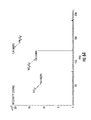
- FIG. 5 shows positive ions produced by the ionization source at a high energy according to an exemplary embodiment.
- FIG. 6A shows negative ions produced by an ionization source configuration that provides significant amounts of energy to air surrounding the discharge according to an exemplary embodiment.
- FIG. 6B shows negative ions produced by another ionization source configuration that provides significant amounts of energy to air surrounding the discharge according to an exemplary embodiment.
- FIG. 7A shows positive ions produced by an ionization source configuration that provides a useful amount of energy to air surrounding the discharge according to an exemplary embodiment.
- FIG. 7B shows negative ions produced by an ionization source configuration that provides a useful amount of energy to air surrounding the discharge according to an exemplary embodiment.
- FIG. 8A shows positive ions produced by two ionization sources on the same platform according to an exemplary embodiment.
- FIG. 8B shows negative ions produced by two ionization sources on the same platform according to an exemplary embodiment.
- FIG. 9A shows DMMP (positive ions) obtained using two ionization sources on the same platform according to an exemplary embodiment.
- FIG. 9B shows DPM (negative ions) obtained using two ionization sources on the same platform according to an exemplary embodiment.
- FIG. 9C shows MES (positive ions) obtained using two ionization sources on the same platform according to an exemplary embodiment.
- FIG. 10A shows the presence of negative ions generated from GB gas in various concentrations according to an exemplary embodiment.
- FIG. 10B shows the presence of positive and negative ions generated from a GD liquid drop on an inert disc according to an exemplary embodiment.
- FIG. 10C shows negative ions generated from a GA liquid drop absorbed into concrete according to an exemplary embodiment.
- FIG. 11B shows a positive ion mass spectrum of ions created by reagent ions from an SCIS device directed onto solid 3,4 dinitrotoluene according to an exemplary embodiment.
- FIGS. 12A and 12B show an ionization source mounted in tubes for ionization of gaseous and/or aerosol samples according to an exemplary embodiment.
- FIG. 12C shows a SCIS creating ions from solid, liquid, or vapor samples according to an exemplary embodiment.
- FIG. 13 shows an SCIS with an electrified mesh screen according to an exemplary embodiment.
- FIGS. 14A to 14C show an SCIS placed behind a device designed to prevent an operator from touching the SCIS according to an exemplary embodiment.
- FIG. 15A shows a frontal perspective view of an SCIS mounted on two printed circuit boards.
- FIG. 15B shows a rear perspective view of an SCIS mounted on two printed circuit boards.
- a soft chemical ionization source includes several components. As described herein, a SCIS may be referred to as an ionization source, a SCIS device, or the SCIS may be incorporated in an ionization source assembly.
- An array of needles protrude from an end of the SCIS device. Each needle has a sharpened point at its distal end. Each needle also has an insulating material that electrically insulates the needle from other needles. This insulating material can be positioned away from the sharpened point.
- a center post In the center of the array of needles is a center post having a shaped tip. This center post may be electrically floating or be attached to a source of voltage.
- the center post may not have any insulation, but is electrically insulated from the needles by the insulating material on each needle.
- the center post must also be insulated from the counterelectrode.
- the insulated needles and the center post are housed within a metal tube known as a counterelectrode. Electrical connectors are coupled to each needle and, if needed, to the center post, such that different voltages and currents (pulsed or unpulsed) can be applied to the needles, the center post, and the counterelectrode.
- the counterelectrode may extend to cover the needles, or an additional open tube may be added to cover the needles. Such coverings change the types, distributions, and amounts of ions formed in the gas discharge.
- At least one ion optic lens can be used in front of the needles to focus and/or to accelerate ions generated in the needle region towards a sample or an analyte.
- Air or other gases can flow around the center post and needle array towards the tips of the needles. Additionally, air or other gases can be introduced beyond the tips of the needles.
- two or more of these SCIS devices can be assembled on one platform to increase the amount of reagent ions produced and to provide simultaneous streams of positive and negative reagent ions.
- the SCIS device can be located within a tube with sample air moving towards, perpendicular to, or away from the device.
- the SCIS device has a flow of energy whereby the reagent ions produce mostly molecular ions from sample molecules.
- the production of these molecular ions may be advantageous because most of the sample molecules are converted to a single ion, rather than a multiplicity of ions, thereby maximizing sensitivity and lowering the minimum amount of a material that can be detected by a given sensor, i.e., the limit of detection.
- the SCIS device examines a sizable target area (on the order of at least one cm 2 ) that is representative of the volume of air, liquid, or solid surface being examined.
- the sample or analyte ions produced can be collected aerodynamically or with the aid of electric lenses that direct the ions to ion detection and identification means, such as an ion mobility spectrometer, a differential mobility spectrometer, or a mass spectrometer. Accordingly, the methods and devices described herein can perform positive ion, negative ion, or simultaneous positive ion and negative ion atmospheric pressure chemical ionization on sample chemicals in air, in liquids or on solids.
- a SCIS device 100 comprises a plurality of needles 110 , each having a distal end 120 .
- the distal end 120 can have a sharpened point or be slightly rounded.
- a sharpened point on distal end 120 of needle 110 is sharpened at an angle greater than 10°, measured from the axis of the needle.
- the needle 110 can be constructed from a material that preferably will not pit or corrode with usage, such as tungsten or stainless steel. After the material is formed into the needle 110 , it may be coated with platinum. As the diameter of the needle 110 increases, the ion output decreases. In one exemplary embodiment, the diameter of needle 110 is 0.04 inches. The needles 110 can have this exemplary diameter regardless of its length.
- the needles 110 can be arranged in a variety of configurations within a counterelectrode 130 in the device 100 .
- the arrangement of needles 110 can be in a circular array or, when using four needles, along the corners of a square.
- four needles 110 are used in the array, but any number of needles can be used.
- seven needles are used.
- the needles 110 within the array can be spaced about 0.18 to 0.25 inches from each other.
- the needles 110 can be arranged substantially parallel to each other or flare out relative to each other. Additionally, the distal ends 120 of each needle 110 are preferably within the same plane.
- the needles 110 are substantially enclosed by an insulating material 140 that may be directly applied and bonded to the needle 110 .
- the insulating material 140 may be wrapped or fitted around the needle 110 such that the needle end opposite the distal end 120 is completely covered.
- the insulating material 140 may be made of Teflon tubing or other suitable insulating material.
- An end 150 of the insulating material 140 closest to the distal end 120 of the needle 110 can optionally be tapered.
- the needles 110 are exposed extending from the insulation material 140 to the distal ends 120 of the needles 110 .
- a needle length of about 0.25 inches is bare from the insulation material 140 to the end of the needle 110 .
- the needle 110 can be attached to a wire so that the needle 110 can be electrified.
- the needle 110 is attached to a wire at the end opposite the distal end 120 .
- FIG. 2 shows a cross-sectional view of the device in FIG. 1 through the line A-A.
- a device 200 has insulating material 240 with needles 210 extending therefrom.
- a center post 260 is positioned substantially in the center of the array of needles 210 .
- the center post 260 can be made of the same material as the needles 210 .
- An end 270 of the center post 260 is not sharpened; rather it is rounded into a hemisphere, ball, or tear-drop shape.
- the center post 260 can have a diameter larger than the diameter of needles 210 . For example, in one embodiment where the diameter of each needle 210 is 0.04 inches, the diameter of the center post 260 can be 0.125 inches.
- the center post 260 can be positioned equidistant from the needles 210 .
- the center post 260 can be about 0.125 inches from each needle 210 .
- the end 270 of the center post 260 can be positioned such that it does not extend as far from the device 200 as the needles 210 .
- the end 270 of the center post 260 is set behind the end of the needles 210 by about 0.125 inches.
- the positioning of the center post 260 can be adjusted based on the plane defined by the ends of the needles 210 .
- the center post 260 has no need for insulation.
- the center post 260 can be covered with insulating material up to the bottom of the curved portion.
- the center post 260 can be coupled to a wire so that the center post 260 can be electrified if necessary.
- the wire is coupled to the center post 260 at an end opposite the end 270 . Removal of the center post 260 can eliminate the discharge between the needles 210 and the counterelectrode 230 . Adjustment of position of the center post 260 can influence the shape and direction of the field around the center post 260 and needles 210 .
- the counterelectrode 230 can also influence the discharge.
- the counterelectrode 230 is made of a metal tube.
- the counterelectrode 230 houses the array of insulated needles 210 and a center post 260 .
- the counterelectrode 230 can have an insulating inner side 280 so that the needles 210 will not arc from the needle 210 to the inside of the counterelectrode 230 .
- An end 290 of the counterelectrode 230 can be positioned in front of the needles 210 , in the same plane as the ends of the needles 210 , or behind the needles 210 .
- a back plate can be used instead of a tube configuration for the counterelectrode 230 .
- a separate tube can be positioned over the needles 210 to confine the discharged plasma.
- This separate tube can be connected to the counterelectrode 230 or it can be a removable tube that fits over the needles 210 and the counterelectrode 230 .
- Positioning the tube over or beyond the needles 210 can significantly change the composition of reactant ions produced and the ions made from samples or analytes.
- by physically changing the spatial distances among the needles, the center post, and the counterelectrode different reactant ions in a variety of distributions and quantities can be formed. Further, by changing the potentials applied to each of these three elements, the types, distributions, and quantities of reactant ions can be changed.
- the same voltage amount can be applied to all needles 210 .
- different voltages, continuous or pulsed, DC or AC, as square waves or other forms can be applied to different needles 210 to achieve different reactant ion compositions.
- the voltage can be in the range of about 3 to 9 kV.
- Air flow can be in the range of about 0.0 to 8.0 L/minute.
- a significant “ion wind” may be produced when the device 200 is turned on in the absence of airflow. This ion wind can be sufficient to deliver ions to a surface, depending upon the application.
- a gas can flow around the center post 260 and needles 210 .
- the gas is ambient air, though it is understood that any gas can be used. However, because ambient air is used, a source of another gas, such as a tank of helium, is not needed to produce the ions.
- the gas can be present in the environment in which the device 200 is being used.
- the device 200 can have one or more capillary tubes that can push or pull the gas through the device 200 to the region about the center post 260 and needles 210 . These tubes or other types of pathways can be positioned between the center post 260 and the needles 210 .
- the addition of a gas containing chemicals that can bind to, or react with, the ions formed by the discharge device can be beneficial in the detection of such ions by providing separation from similar species or from interferents.
- Different configurations of one or more SCIS devices can produce different results. Two or more SCIS devices can be positioned close to one another such that the amount of ions produced from the combination is greater than the aggregate amount of ions produced by those SCIS devices separately.
- FIG. 3 a dual SCIS device configuration is shown. In this configuration, a first reagent ionization source device 300 and a second reagent ionization source device 305 positioned on a platform 320 are directed at a sample (not shown) positioned beyond the end of the arrays of needles 310 , 315 .
- the first device 300 and the second device 305 can be in a parallel alignment. Each device 300 , 305 can be run at the same potential and polarity or at different potentials and polarities. If different polarities are used for each device 300 , 305 , positive and negative ions can be produced simultaneously.
- each device 300 , 305 can have opposite polarity. By positioning the devices in close proximity to each other, the ion distribution can be changed and the amount of ions produced can be increased at least four to six times. This configuration also produces more ions at less power. The configuration also results in a shift from ion clusters H + (H 2 O) 2-4 to H + (H 2 O) 1-2 . This declustering can be useful because a positive ion is more likely to react with sample molecules if it is surrounded by less water molecules. This effect is shown in FIGS. 8A , 8 B, 9 A, 9 B, and 9 C, as compared to FIGS. 7A and 7B . FIGS.
- FIGS. 7A and 7B show positive and negative ions, respectively, produced by a single ionization source first operated in positive mode, then in negative mode.
- FIGS. 8A and 8B show positive ions and negative ions, respectively, produced by two ionization sources on the same platform according to an exemplary embodiment.
- FIGS. 9A and 9B show DMMP (positive ions) and DPM (negative ions) obtained using two ionization sources on the same platform.
- FIG. 9C shows MES (positive ions) obtained using two ionization sources on the same platform.
- FIGS. 7A and 7B show different positive ion and negative ion clusters and amounts than those shown in FIGS. 8A , 8 B, 9 A, 9 B, and 9 C.
- changing operating voltages can raise or lower all ions produced, or can increase one type of ion, while reducing the amount of other ions. For example, if the potential on a positive ionization source is zero, and the potential on a negative ionization source is varied from ⁇ 3.2 kV to ⁇ 7.8 kV, then an ion peak at 32 amu (O 2 ) and the ion peak at 60 amu (CO 3 ⁇ ) both decrease linearly as the potential changes from ⁇ 3.2 kV to ⁇ 7.8 kV.
- a negative ion peak at 32 amu is three times larger than all other ion peaks combined and six times larger than the ion peak at 60 amu.
- There are only traces of O 3 ⁇ , NO 2 ⁇ , and NO 3 ⁇ (combined 5% of the O 2 ⁇ peak).
- each ionization source can act like a point source in that it produces a three dimensional cloud or field of ions that reaches in front of, around, and behind the needles. Hence, there is little degradation in the number of ions produced and, as the ionization source is moved relative to a target, there is little difficulty in ions reaching the target. Also, this means that the ion source can be either perpendicular or parallel to the sample or surface upon which the sample resides and still produce sample ions. If the two ionization sources have opposite polarities, then the positive ions predominate on one side, the negative ions predominate on the other side, and a volume around the center line has both types of ions. In an alternative embodiment, an ion optic lens can be used to focus the ions.
- Ambient air 420 can flow around a center post 460 and needle array 410 of an SCIS device 400 towards a target sample surface 430 .
- the center post 460 and needle array 410 of the SCIS device 400 ionize the ambient air 420 to produce reagent ions 440 in the vicinity of the target sample surface 430 .
- the reagent ions can be present in the vicinity of the center post 460 and needles 410 , whereby this field is directed to interact with the sample surface 430 .
- the field is a spherical region centered about the center post 460 having a diameter of about four inches.
- the reagent ions 440 interact with the un-ionized chemicals or gas at the target sample surface 430 to discharge sample ions 450 .
- the flow of ambient air 420 around the center post 460 is not necessary for the production of ions.
- Ambient air 420 around the needle array 410 is usually sufficient for ion production.
- the discharged ions 450 can be directed to ion collection, transmission, transfer, detection, and/or identification means.
- an ion optic lens 470 can be used to focus and/or to accelerate ions generated in the needle region towards the sample surface 430 .
- positive ions are shown, though it is recognized that a similar process is used for negative ions.
- the SCIS device can be used to produce both positive and negative ions, as well as mainly positive ions or mainly negative ions. In one embodiment, the SCIS device can produce more than 90% positive ions. In another embodiment, the SCIS device can produce more than 90% negative ions. Also, although ambient air is used in this exemplary embodiment, other types of reagent gases can be used.
- FIGS. 5 , 6 A, 6 B, 7 A, and 7 B SCISs produced ions that were detected by a time-of-flight (TOF) mass spectrometer and the spectra are plotted as intensity versus mass-to-charge ratio (m/z).
- FIGS. 5 , 6 A, and 6 B show spectra obtained by placing a tube or sheath over the needles.
- FIG. 5 shows positive ions produced by the ionization source at a high energy.
- FIGS. 6A and 6B show negative ions produced by an ionization source configuration that provides significant amounts of energy to air surrounding the discharge. Confining the discharge leads to the formation of ions requiring more energy to produce.
- FIGS. 7A and 7B show positive ions and negative ions, respectively, produced by an ionization source configuration, not having a sheath or tube over the needles, that provides an amount of energy to air surrounding the discharge to create enough ions without using a lot of power.
- selectivity can be achieved by using a different gas that has a different ionization potential.
- gases include, but are not limited to, helium, ammonia (10.2 eV), acetone (9.7 eV), and di n-propylamine (7.8 eV).
- Reactant ions from each of these gases would ionize chemicals having ionization potentials less than that of the respective gas. Accordingly, selectivity can be based on ionization potential.
- the ions in the gas can combine with the sample or analyte ions to produce ion/molecular clusters that can aid in analyte ion identification and separation.
- FIGS. 9A and 9B show DMMP (positive ions) and DPM (negative ions) obtained using two ionization sources on the same platform
- FIG. 9C shows MES (positive ions) obtained using two ionization sources on the same platform
- FIGS. 11A and 11B show a negative ion mass spectrum and a positive ion mass spectrum, respectively, of ions created by reagent ions from an SCIS device directed onto solid 3,4 dinitrotoluene.
- FIGS. 10A to 10C subsequent detection by this spectrometer is shown.
- FIG. 10A shows the presence of negative ions generated from GB gas (sarin) in various concentrations, ranging from 170 parts per trillion to 180 parts per billion
- FIG. 10B shows the presence of positive and negative ions generated from GD (soman) on a inert disc
- FIG. 10C shows negative ions generated from GA (tabun) absorbed into concrete.
- the SCIS device can be used in detecting, for example, parts per trillion of chemical warfare agents (CWAs) in the form of vapor; liquid CWAs on plastic surfaces, solid porous concrete, and other surfaces; and solid explosives.
- CWAs chemical warfare agents
- FIG. 12A shows an ionization source mounted in tubes for ionization of gaseous and/or aerosol samples.
- a SCIS 1200 is mounted in a tube 1210 having air flow plus a sample into a first end 1220 of the tube 1210 . Accordingly, ions exit the tube 1210 at a second end 1230 .
- FIG. 12B shows an ionization source mounted in tubes for ionization of gaseous and/or aerosol samples, according to an alternative embodiment.
- a SCIS 1201 is mounted in a tube 1211 . Air flow plus a sample enters the tube 1211 at a first end 1221 .
- a passageway 1241 can be used to provide air of a different composition than that of the air flow in the first end 1221 . For example, a dopant or other chemical that binds to, or reacts with the sample molecules can be added this way in order to modify the properties of the sample ions for detection.
- the generated ions exit the tube 1211 at a second end 1231 .
- FIG. 12C shows a SCIS 1212 for creating ions from a solid examination target 1250 , a liquid examination target 1251 , or a vapor examination target 1252 .
- a wire mesh screen 1320 can be used with a SCIS device 1300 .
- the screen is positioned around an array of needles 1310 and projects forward past the needles 1310 .
- the screen 1320 can enhance the amount of ions detected at about one inch from the end of the screen by about 25% relative to the same configuration without the screen 1320 .
- an SCIS device 1400 can be positioned behind a shield 1410 designed to prevent an operator from touching the SCIS device 1400 to ensure the performance of the SCIS device 1400 is not affected.
- FIG. 14A shows a frontal perspective view of the shield 1410
- FIG. 14B shows a closer frontal perspective view of shield 1410
- FIG. 14C shows a rear perspective view of shield 1410 .
- Shield 1410 has an upper surface 1420 , two side surfaces 1430 , and a lower surface 1440 that form an enclosure.
- a vertical support 1450 extending from the upper surface 1420 to the lower surface 1440 holds the SCIS device 1400 in position with the enclosure.
- the shield 1410 has two vertical supports 1450 .
- the shield configuration can be varied depending upon the number of SCIS devices. Additionally, the orientation of the support can also be varied.
- the enclosure has a plurality of vertical members 1460 extending from the upper surface 1420 to the lower surface 1440 , a plurality of horizontal members 1470 extending from one side surface 1430 to the other side surface 1430 . It is intended that the spacing, number, and configuration of vertical members 1460 and horizontal members 1470 can vary depending on the intended purpose and the configuration of the SCIS device.
- the needles, center post, counterelectrode, and insulation can be mounted on two small printed circuit boards.
- this configuration makes a SCIS device 1500 very easy to integrate into a system or platform from an installation and replacement perspective in that no wiring or soldering is needed—the device is simply fastened over electrical contacts.
- the construction of the SCIS device 1500 is divided into a forward plane 1550 and an aft plane 1560 .
- the forward plane 1550 has a metal ring 1530 at a first potential.
- the forward plane 1550 is 1.0 inch ⁇ 0.5 inches.
- the aft plane 1560 has four needles 1510 to which a high voltage potential is applied (relative to the metal ring 1530 ).
- the aft plane 1560 is 0.5 inches ⁇ 0.5 inches.
- the planes are separated by insulating hardware affording the ability to adjust the distance between planes 1550 , 1560 (and consequently the distance between the needles 1510 and the metal ring 1530 ). This allows the adjustment of the potential at which the SCIS device 1500 fires, as well as the current necessary to maintain ion production.
- the spacing between needles 1510 , and the spacing between needles 1510 and the center post 1520 can be tightly controlled during printed circuit board manufacture. The overall part count, size, complexity, and manufacturability of the SCIS device 1500 are significantly reduced.
Abstract
Description
Claims (8)
Priority Applications (1)
| Application Number | Priority Date | Filing Date | Title |
|---|---|---|---|
| US12/400,831 US8071957B1 (en) | 2009-03-10 | 2009-03-10 | Soft chemical ionization source |
Applications Claiming Priority (1)
| Application Number | Priority Date | Filing Date | Title |
|---|---|---|---|
| US12/400,831 US8071957B1 (en) | 2009-03-10 | 2009-03-10 | Soft chemical ionization source |
Publications (1)
| Publication Number | Publication Date |
|---|---|
| US8071957B1 true US8071957B1 (en) | 2011-12-06 |
Family
ID=45034397
Family Applications (1)
| Application Number | Title | Priority Date | Filing Date |
|---|---|---|---|
| US12/400,831 Expired - Fee Related US8071957B1 (en) | 2009-03-10 | 2009-03-10 | Soft chemical ionization source |
Country Status (1)
| Country | Link |
|---|---|
| US (1) | US8071957B1 (en) |
Cited By (4)
| Publication number | Priority date | Publication date | Assignee | Title |
|---|---|---|---|---|
| CN103928287A (en) * | 2014-04-17 | 2014-07-16 | 桂林电子科技大学 | Ion source and air pump integration device and application thereof |
| CN104752148A (en) * | 2013-12-30 | 2015-07-01 | 同方威视技术股份有限公司 | Corona discharge assembly and ion migration spectrometer provided with same |
| US20150206726A1 (en) * | 2009-08-19 | 2015-07-23 | Parisa A. Ariya | Method and system for the quantitative chemical speciation of heavy metals and other toxic pollutants |
| CN111540666A (en) * | 2020-04-20 | 2020-08-14 | 清华大学深圳国际研究生院 | Ion wind generating device and application thereof |
Citations (123)
| Publication number | Priority date | Publication date | Assignee | Title |
|---|---|---|---|---|
| US3708661A (en) * | 1970-02-21 | 1973-01-02 | Philips Corp | Corona discharge for electro-static charging |
| US4000918A (en) | 1975-10-20 | 1977-01-04 | General Signal Corporation | Ferrule for liquid tight flexible metal conduit |
| US4159423A (en) | 1976-10-01 | 1979-06-26 | Hitachi, Ltd. | Chemical ionization ion source |
| US4209696A (en) | 1977-09-21 | 1980-06-24 | Fite Wade L | Methods and apparatus for mass spectrometric analysis of constituents in liquids |
| US4256335A (en) | 1977-05-23 | 1981-03-17 | Nielsen Jr Anker J | Positive locking terminal bushings for flexible tubing |
| US4271357A (en) | 1978-05-26 | 1981-06-02 | Pye (Electronic Products) Limited | Trace vapor detection |
| US4300004A (en) | 1978-12-23 | 1981-11-10 | Bayer Aktiengesellschaft | Process for the preparation of dichlorobenzenes |
| US4318028A (en) | 1979-07-20 | 1982-03-02 | Phrasor Scientific, Inc. | Ion generator |
| US4468468A (en) | 1981-06-27 | 1984-08-28 | Bayer Aktiengesellschaft | Process for the selective analysis of individual trace-like components in gases and liquid |
| US4531056A (en) | 1983-04-20 | 1985-07-23 | Yale University | Method and apparatus for the mass spectrometric analysis of solutions |
| US4542293A (en) | 1983-04-20 | 1985-09-17 | Yale University | Process and apparatus for changing the energy of charged particles contained in a gaseous medium |
| US4546253A (en) | 1982-08-20 | 1985-10-08 | Masahiko Tsuchiya | Apparatus for producing sample ions |
| GB2127212B (en) | 1982-08-20 | 1987-08-12 | Tsuchiya Masahiko | Apparatus for producing sample ions |
| US4789783A (en) | 1987-04-02 | 1988-12-06 | Cook Robert D | Discharge ionization detector |
| US4855595A (en) | 1986-07-03 | 1989-08-08 | Allied-Signal Inc. | Electric field control in ion mobility spectrometry |
| US4888482A (en) * | 1987-03-30 | 1989-12-19 | Hitachi, Ltd. | Atmospheric pressure ionization mass spectrometer |
| US4948962A (en) | 1988-06-10 | 1990-08-14 | Hitachi, Ltd. | Plasma ion source mass spectrometer |
| US4974648A (en) | 1989-02-27 | 1990-12-04 | Steyr-Daimler-Puch Ag | Implement for lopping felled trees |
| US4976920A (en) | 1987-07-14 | 1990-12-11 | Adir Jacob | Process for dry sterilization of medical devices and materials |
| US4977320A (en) | 1990-01-22 | 1990-12-11 | The Rockefeller University | Electrospray ionization mass spectrometer with new features |
| US4999492A (en) | 1989-03-23 | 1991-03-12 | Seiko Instruments, Inc. | Inductively coupled plasma mass spectrometry apparatus |
| US5142143A (en) | 1990-10-31 | 1992-08-25 | Extrel Corporation | Method and apparatus for preconcentration for analysis purposes of trace constitutes in gases |
| US5141532A (en) | 1990-09-28 | 1992-08-25 | The Regents Of The University Of Michigan | Thermal modulation inlet for gas chromatography system |
| US5164704A (en) | 1990-03-16 | 1992-11-17 | Ericsson Radio Systems B.V. | System for transmitting alarm signals with a repetition |
| US5168068A (en) | 1989-06-20 | 1992-12-01 | President And Fellows Of Harvard College | Adsorbent-type gas monitor |
| US5171525A (en) | 1987-02-25 | 1992-12-15 | Adir Jacob | Process and apparatus for dry sterilization of medical devices and materials |
| US5192865A (en) | 1992-01-14 | 1993-03-09 | Cetac Technologies Inc. | Atmospheric pressure afterglow ionization system and method of use, for mass spectrometer sample analysis systems |
| US5280175A (en) | 1991-09-17 | 1994-01-18 | Bruker Saxonia Analytik Gmbh | Ion mobility spectrometer drift chamber |
| US5305015A (en) | 1990-08-16 | 1994-04-19 | Hewlett-Packard Company | Laser ablated nozzle member for inkjet printhead |
| US5304797A (en) | 1992-02-27 | 1994-04-19 | Hitachi, Ltd. | Gas analyzer for determining impurity concentration of highly-purified gas |
| US5306910A (en) | 1992-04-10 | 1994-04-26 | Millipore Corporation | Time modulated electrified spray apparatus and process |
| US5338931A (en) | 1992-04-23 | 1994-08-16 | Environmental Technologies Group, Inc. | Photoionization ion mobility spectrometer |
| US5412209A (en) | 1991-11-27 | 1995-05-02 | Hitachi, Ltd. | Electron beam apparatus |
| US5412208A (en) | 1994-01-13 | 1995-05-02 | Mds Health Group Limited | Ion spray with intersecting flow |
| US5485016A (en) | 1993-04-26 | 1996-01-16 | Hitachi, Ltd. | Atmospheric pressure ionization mass spectrometer |
| US5541519A (en) | 1991-02-28 | 1996-07-30 | Stearns; Stanley D. | Photoionization detector incorporating a dopant and carrier gas flow |
| US5559326A (en) | 1995-07-28 | 1996-09-24 | Hewlett-Packard Company | Self generating ion device for mass spectrometry of liquids |
| US5581081A (en) | 1993-12-09 | 1996-12-03 | Hitachi, Ltd. | Method and apparatus for direct coupling of liquid chromatograph and mass spectrometer, liquid chromatograph-mass spectrometry, and liquid chromatograph mass spectrometer |
| US5587581A (en) | 1995-07-31 | 1996-12-24 | Environmental Technologies Group, Inc. | Method and an apparatus for an air sample analysis |
| US5625184A (en) | 1995-05-19 | 1997-04-29 | Perseptive Biosystems, Inc. | Time-of-flight mass spectrometry analysis of biomolecules |
| GB2288061B (en) | 1994-03-10 | 1997-10-15 | Bruker Franzen Analytik Gmbh | Electrospraying method for mass spectrometric analysis |
| US5684300A (en) * | 1991-12-03 | 1997-11-04 | Taylor; Stephen John | Corona discharge ionization source |
| US5736740A (en) | 1995-04-25 | 1998-04-07 | Bruker-Franzen Analytik Gmbh | Method and device for transport of ions in gas through a capillary |
| US5747799A (en) | 1995-06-02 | 1998-05-05 | Bruker-Franzen Analytik Gmbh | Method and device for the introduction of ions into the gas stream of an aperture to a mass spectrometer |
| US5750988A (en) | 1994-07-11 | 1998-05-12 | Hewlett-Packard Company | Orthogonal ion sampling for APCI mass spectrometry |
| US5753910A (en) | 1996-07-12 | 1998-05-19 | Hewlett-Packard Company | Angled chamber seal for atmospheric pressure ionization mass spectrometry |
| US5756994A (en) | 1995-12-14 | 1998-05-26 | Micromass Limited | Electrospray and atmospheric pressure chemical ionization mass spectrometer and ion source |
| US5798146A (en) | 1995-09-14 | 1998-08-25 | Tri-Star Technologies | Surface charging to improve wettability |
| US5828062A (en) | 1997-03-03 | 1998-10-27 | Waters Investments Limited | Ionization electrospray apparatus for mass spectrometry |
| US5838002A (en) | 1996-08-21 | 1998-11-17 | Chem-Space Associates, Inc | Method and apparatus for improved electrospray analysis |
| US5873523A (en) | 1996-02-29 | 1999-02-23 | Yale University | Electrospray employing corona-assisted cone-jet mode |
| US5892364A (en) | 1997-09-11 | 1999-04-06 | Monagle; Matthew | Trace constituent detection in inert gases |
| US5903804A (en) | 1996-09-30 | 1999-05-11 | Science Applications International Corporation | Printer and/or scanner and/or copier using a field emission array |
| US5945678A (en) | 1996-05-21 | 1999-08-31 | Hamamatsu Photonics K.K. | Ionizing analysis apparatus |
| US5965884A (en) | 1998-06-04 | 1999-10-12 | The Regents Of The University Of California | Atmospheric pressure matrix assisted laser desorption |
| US5986259A (en) | 1996-04-23 | 1999-11-16 | Hitachi, Ltd. | Mass spectrometer |
| US6040575A (en) | 1998-01-23 | 2000-03-21 | Analytica Of Branford, Inc. | Mass spectrometry from surfaces |
| US6060705A (en) | 1997-12-10 | 2000-05-09 | Analytica Of Branford, Inc. | Electrospray and atmospheric pressure chemical ionization sources |
| US6107628A (en) | 1998-06-03 | 2000-08-22 | Battelle Memorial Institute | Method and apparatus for directing ions and other charged particles generated at near atmospheric pressures into a region under vacuum |
| US6124675A (en) | 1998-06-01 | 2000-09-26 | University Of Montreal | Metastable atom bombardment source |
| US6147345A (en) | 1997-10-07 | 2000-11-14 | Chem-Space Associates | Method and apparatus for increased electrospray ion production |
| US6207954B1 (en) | 1997-09-12 | 2001-03-27 | Analytica Of Branford, Inc. | Multiple sample introduction mass spectrometry |
| US6223584B1 (en) | 1999-05-27 | 2001-05-01 | Rvm Scientific, Inc. | System and method for vapor constituents analysis |
| US6225623B1 (en) | 1996-02-02 | 2001-05-01 | Graseby Dynamics Limited | Corona discharge ion source for analytical instruments |
| WO2001033605A2 (en) | 1999-10-29 | 2001-05-10 | Rijksuniversiteit Groningen | Atmospheric pressure photoionization (appi): a new ionization method for liquid chromatography-mass spectrometry |
| US6239428B1 (en) | 1999-03-03 | 2001-05-29 | Massachusetts Institute Of Technology | Ion mobility spectrometers and methods |
| US6278111B1 (en) | 1995-08-21 | 2001-08-21 | Waters Investments Limited | Electrospray for chemical analysis |
| US6309610B1 (en) | 1998-05-27 | 2001-10-30 | Science Applications International Corporation | Non-thermal plasma apparatus utilizing dielectrically-coated electrodes for treating effluent gas |
| US20020011560A1 (en) | 2000-06-09 | 2002-01-31 | Sheehan Edward W. | Apparatus and method for focusing ions and charged particles at atmospheric pressure |
| US6359275B1 (en) | 1999-07-14 | 2002-03-19 | Agilent Technologies, Inc. | Dielectric conduit with end electrodes |
| US6455846B1 (en) | 1999-10-14 | 2002-09-24 | Battelle Memorial Institute | Sample inlet tube for ion source |
| US6462338B1 (en) | 1998-09-02 | 2002-10-08 | Shimadzu Corporation | Mass spectrometer |
| US6465776B1 (en) | 2000-06-02 | 2002-10-15 | Board Of Regents, The University Of Texas System | Mass spectrometer apparatus for analyzing multiple fluid samples concurrently |
| US6486469B1 (en) | 1999-10-29 | 2002-11-26 | Agilent Technologies, Inc. | Dielectric capillary high pass ion filter |
| US20020175278A1 (en) | 2001-05-25 | 2002-11-28 | Whitehouse Craig M. | Atmospheric and vacuum pressure MALDI ion source |
| US20020185593A1 (en) | 2001-04-26 | 2002-12-12 | Bruker Saxonia Analytik Gmbh | Ion mobility spectrometer with non-radioactive ion source |
| US20020185595A1 (en) | 2001-05-18 | 2002-12-12 | Smith Richard D. | Ionization source utilizing a multi-capillary inlet and method of operation |
| US6495823B1 (en) | 1999-07-21 | 2002-12-17 | The Charles Stark Draper Laboratory, Inc. | Micromachined field asymmetric ion mobility filter and detection system |
| US6512224B1 (en) | 1999-07-21 | 2003-01-28 | The Charles Stark Draper Laboratory, Inc. | Longitudinal field driven field asymmetric ion mobility filter and detection system |
| US20030038236A1 (en) | 1999-10-29 | 2003-02-27 | Russ Charles W. | Atmospheric pressure ion source high pass ion filter |
| US6537817B1 (en) | 1993-05-31 | 2003-03-25 | Packard Instrument Company | Piezoelectric-drop-on-demand technology |
| US6583408B2 (en) | 2001-05-18 | 2003-06-24 | Battelle Memorial Institute | Ionization source utilizing a jet disturber in combination with an ion funnel and method of operation |
| US6583407B1 (en) | 1999-10-29 | 2003-06-24 | Agilent Technologies, Inc. | Method and apparatus for selective ion delivery using ion polarity independent control |
| US6593570B2 (en) | 2000-05-24 | 2003-07-15 | Agilent Technologies, Inc. | Ion optic components for mass spectrometers |
| US6610986B2 (en) | 2001-10-31 | 2003-08-26 | Ionfinity Llc | Soft ionization device and applications thereof |
| US20030197121A1 (en) | 2002-03-08 | 2003-10-23 | Frantisek Turecek | Preparative separation of mixtures by mass spectrometry |
| US6649907B2 (en) | 2001-03-08 | 2003-11-18 | Wisconsin Alumni Research Foundation | Charge reduction electrospray ionization ion source |
| US6683301B2 (en) | 2001-01-29 | 2004-01-27 | Analytica Of Branford, Inc. | Charged particle trapping in near-surface potential wells |
| US6690004B2 (en) | 1999-07-21 | 2004-02-10 | The Charles Stark Draper Laboratory, Inc. | Method and apparatus for electrospray-augmented high field asymmetric ion mobility spectrometry |
| US6727496B2 (en) | 2001-08-14 | 2004-04-27 | Sionex Corporation | Pancake spectrometer |
| US6750449B2 (en) | 1999-02-25 | 2004-06-15 | Clemson University | Sampling and analysis of airborne particulate matter by glow discharge atomic emission and mass spectrometries |
| US20040161856A1 (en) | 2003-02-18 | 2004-08-19 | Robert Handly | Chemical agent monitoring system |
| US6784424B1 (en) | 2001-05-26 | 2004-08-31 | Ross C Willoughby | Apparatus and method for focusing and selecting ions and charged particles at or near atmospheric pressure |
| US6815668B2 (en) | 1999-07-21 | 2004-11-09 | The Charles Stark Draper Laboratory, Inc. | Method and apparatus for chromatography-high field asymmetric waveform ion mobility spectrometry |
| US6818889B1 (en) | 2002-06-01 | 2004-11-16 | Edward W. Sheehan | Laminated lens for focusing ions from atmospheric pressure |
| US6822225B2 (en) | 2002-09-25 | 2004-11-23 | Ut-Battelle Llc | Pulsed discharge ionization source for miniature ion mobility spectrometers |
| US20040245458A1 (en) | 2003-06-07 | 2004-12-09 | Sheehan Edward W. | Ion enrichment aperture arrays |
| US6852970B2 (en) | 2002-11-08 | 2005-02-08 | Hitachi, Ltd. | Mass spectrometer |
| US6852969B2 (en) | 2001-01-29 | 2005-02-08 | Clemson University | Atmospheric pressure, glow discharge, optical emission source for the direct sampling of liquid media |
| US6867415B2 (en) | 2000-08-24 | 2005-03-15 | Newton Scientific, Inc. | Sample introduction interface for analytical processing |
| US20050056775A1 (en) | 2003-04-04 | 2005-03-17 | Jeol Usa, Inc. | Atmospheric pressure ion source |
| US6878930B1 (en) | 2003-02-24 | 2005-04-12 | Ross Clark Willoughby | Ion and charged particle source for production of thin films |
| US6888132B1 (en) | 2002-06-01 | 2005-05-03 | Edward W Sheehan | Remote reagent chemical ionization source |
| US20050196871A1 (en) | 2003-04-04 | 2005-09-08 | Jeol Usa, Inc. | Method for atmospheric pressure analyte ionization |
| US6943347B1 (en) | 2002-10-18 | 2005-09-13 | Ross Clark Willoughby | Laminated tube for the transport of charged particles contained in a gaseous medium |
| US6949740B1 (en) | 2002-09-13 | 2005-09-27 | Edward William Sheehan | Laminated lens for introducing gas-phase ions into the vacuum systems of mass spectrometers |
| US6998605B1 (en) | 2000-05-25 | 2006-02-14 | Agilent Technologies, Inc. | Apparatus for delivering ions from a grounded electrospray assembly to a vacuum chamber |
| US7005634B2 (en) | 2001-03-29 | 2006-02-28 | Anelva Corporation | Ionization apparatus |
| US7053367B2 (en) | 2001-11-07 | 2006-05-30 | Hitachi High-Technologies Corporation | Mass spectrometer |
| US7057168B2 (en) | 1999-07-21 | 2006-06-06 | Sionex Corporation | Systems for differential ion mobility analysis |
| US7064320B2 (en) | 2004-09-16 | 2006-06-20 | Hitachi, Ltd. | Mass chromatograph |
| US7078068B2 (en) | 2001-10-15 | 2006-07-18 | Astaris L.L.C. | Methods for coagulating collagen using phosphate brine solutions |
| US7083112B2 (en) | 1991-04-24 | 2006-08-01 | Aerogen, Inc. | Method and apparatus for dispensing liquids as an atomized spray |
| US7087898B2 (en) | 2000-06-09 | 2006-08-08 | Willoughby Ross C | Laser desorption ion source |
| US7091493B2 (en) | 2003-02-26 | 2006-08-15 | Yamanashi Tlo Co., Ltd. | Method of and apparatus for ionizing sample gas |
| US7095019B1 (en) | 2003-05-30 | 2006-08-22 | Chem-Space Associates, Inc. | Remote reagent chemical ionization source |
| US20060249671A1 (en) | 2005-05-05 | 2006-11-09 | Eai Corporation | Method and device for non-contact sampling and detection |
| US20070114389A1 (en) | 2005-11-08 | 2007-05-24 | Karpetsky Timothy P | Non-contact detector system with plasma ion source |
| US7253406B1 (en) | 2002-06-01 | 2007-08-07 | Chem-Space Associates, Incorporated | Remote reagent chemical ionization source |
| US7274015B2 (en) | 2001-08-08 | 2007-09-25 | Sionex Corporation | Capacitive discharge plasma ion source |
| US20080296493A1 (en) | 2007-06-02 | 2008-12-04 | Ross Clark Willoughby | Enriichment tube for sampling ions |
| US20090294660A1 (en) * | 2008-05-30 | 2009-12-03 | Craig Whitehouse | Single and multiple operating mode ion sources with atmospheric pressure chemical ionization |
| US20100059689A1 (en) | 2007-01-17 | 2010-03-11 | Shigeyoshi Horiike | Ionization emitter, ionization apparatus, and method for manufacturing ionization emitter |
-
2009
- 2009-03-10 US US12/400,831 patent/US8071957B1/en not_active Expired - Fee Related
Patent Citations (143)
| Publication number | Priority date | Publication date | Assignee | Title |
|---|---|---|---|---|
| US3708661A (en) * | 1970-02-21 | 1973-01-02 | Philips Corp | Corona discharge for electro-static charging |
| US4000918A (en) | 1975-10-20 | 1977-01-04 | General Signal Corporation | Ferrule for liquid tight flexible metal conduit |
| US4159423A (en) | 1976-10-01 | 1979-06-26 | Hitachi, Ltd. | Chemical ionization ion source |
| US4256335A (en) | 1977-05-23 | 1981-03-17 | Nielsen Jr Anker J | Positive locking terminal bushings for flexible tubing |
| US4209696A (en) | 1977-09-21 | 1980-06-24 | Fite Wade L | Methods and apparatus for mass spectrometric analysis of constituents in liquids |
| US4271357A (en) | 1978-05-26 | 1981-06-02 | Pye (Electronic Products) Limited | Trace vapor detection |
| US4300004A (en) | 1978-12-23 | 1981-11-10 | Bayer Aktiengesellschaft | Process for the preparation of dichlorobenzenes |
| US4318028A (en) | 1979-07-20 | 1982-03-02 | Phrasor Scientific, Inc. | Ion generator |
| US4468468A (en) | 1981-06-27 | 1984-08-28 | Bayer Aktiengesellschaft | Process for the selective analysis of individual trace-like components in gases and liquid |
| GB2127212B (en) | 1982-08-20 | 1987-08-12 | Tsuchiya Masahiko | Apparatus for producing sample ions |
| US4546253A (en) | 1982-08-20 | 1985-10-08 | Masahiko Tsuchiya | Apparatus for producing sample ions |
| US4542293A (en) | 1983-04-20 | 1985-09-17 | Yale University | Process and apparatus for changing the energy of charged particles contained in a gaseous medium |
| US4531056A (en) | 1983-04-20 | 1985-07-23 | Yale University | Method and apparatus for the mass spectrometric analysis of solutions |
| US4855595A (en) | 1986-07-03 | 1989-08-08 | Allied-Signal Inc. | Electric field control in ion mobility spectrometry |
| US5171525A (en) | 1987-02-25 | 1992-12-15 | Adir Jacob | Process and apparatus for dry sterilization of medical devices and materials |
| US4888482A (en) * | 1987-03-30 | 1989-12-19 | Hitachi, Ltd. | Atmospheric pressure ionization mass spectrometer |
| US4789783A (en) | 1987-04-02 | 1988-12-06 | Cook Robert D | Discharge ionization detector |
| US4976920A (en) | 1987-07-14 | 1990-12-11 | Adir Jacob | Process for dry sterilization of medical devices and materials |
| US4948962A (en) | 1988-06-10 | 1990-08-14 | Hitachi, Ltd. | Plasma ion source mass spectrometer |
| US4974648A (en) | 1989-02-27 | 1990-12-04 | Steyr-Daimler-Puch Ag | Implement for lopping felled trees |
| US4999492A (en) | 1989-03-23 | 1991-03-12 | Seiko Instruments, Inc. | Inductively coupled plasma mass spectrometry apparatus |
| US5168068A (en) | 1989-06-20 | 1992-12-01 | President And Fellows Of Harvard College | Adsorbent-type gas monitor |
| US4977320A (en) | 1990-01-22 | 1990-12-11 | The Rockefeller University | Electrospray ionization mass spectrometer with new features |
| US5164704A (en) | 1990-03-16 | 1992-11-17 | Ericsson Radio Systems B.V. | System for transmitting alarm signals with a repetition |
| US5305015A (en) | 1990-08-16 | 1994-04-19 | Hewlett-Packard Company | Laser ablated nozzle member for inkjet printhead |
| US5141532A (en) | 1990-09-28 | 1992-08-25 | The Regents Of The University Of Michigan | Thermal modulation inlet for gas chromatography system |
| US5142143A (en) | 1990-10-31 | 1992-08-25 | Extrel Corporation | Method and apparatus for preconcentration for analysis purposes of trace constitutes in gases |
| US5541519A (en) | 1991-02-28 | 1996-07-30 | Stearns; Stanley D. | Photoionization detector incorporating a dopant and carrier gas flow |
| US7083112B2 (en) | 1991-04-24 | 2006-08-01 | Aerogen, Inc. | Method and apparatus for dispensing liquids as an atomized spray |
| US5280175A (en) | 1991-09-17 | 1994-01-18 | Bruker Saxonia Analytik Gmbh | Ion mobility spectrometer drift chamber |
| US5412209A (en) | 1991-11-27 | 1995-05-02 | Hitachi, Ltd. | Electron beam apparatus |
| US5684300A (en) * | 1991-12-03 | 1997-11-04 | Taylor; Stephen John | Corona discharge ionization source |
| US5192865A (en) | 1992-01-14 | 1993-03-09 | Cetac Technologies Inc. | Atmospheric pressure afterglow ionization system and method of use, for mass spectrometer sample analysis systems |
| US5304797A (en) | 1992-02-27 | 1994-04-19 | Hitachi, Ltd. | Gas analyzer for determining impurity concentration of highly-purified gas |
| US5436446A (en) | 1992-04-10 | 1995-07-25 | Waters Investments Limited | Analyzing time modulated electrospray |
| US5306910A (en) | 1992-04-10 | 1994-04-26 | Millipore Corporation | Time modulated electrified spray apparatus and process |
| US5338931A (en) | 1992-04-23 | 1994-08-16 | Environmental Technologies Group, Inc. | Photoionization ion mobility spectrometer |
| US5485016A (en) | 1993-04-26 | 1996-01-16 | Hitachi, Ltd. | Atmospheric pressure ionization mass spectrometer |
| US6537817B1 (en) | 1993-05-31 | 2003-03-25 | Packard Instrument Company | Piezoelectric-drop-on-demand technology |
| US5581081A (en) | 1993-12-09 | 1996-12-03 | Hitachi, Ltd. | Method and apparatus for direct coupling of liquid chromatograph and mass spectrometer, liquid chromatograph-mass spectrometry, and liquid chromatograph mass spectrometer |
| US5412208A (en) | 1994-01-13 | 1995-05-02 | Mds Health Group Limited | Ion spray with intersecting flow |
| GB2288061B (en) | 1994-03-10 | 1997-10-15 | Bruker Franzen Analytik Gmbh | Electrospraying method for mass spectrometric analysis |
| US5750988A (en) | 1994-07-11 | 1998-05-12 | Hewlett-Packard Company | Orthogonal ion sampling for APCI mass spectrometry |
| US5736740A (en) | 1995-04-25 | 1998-04-07 | Bruker-Franzen Analytik Gmbh | Method and device for transport of ions in gas through a capillary |
| US5625184A (en) | 1995-05-19 | 1997-04-29 | Perseptive Biosystems, Inc. | Time-of-flight mass spectrometry analysis of biomolecules |
| US5747799A (en) | 1995-06-02 | 1998-05-05 | Bruker-Franzen Analytik Gmbh | Method and device for the introduction of ions into the gas stream of an aperture to a mass spectrometer |
| US5559326A (en) | 1995-07-28 | 1996-09-24 | Hewlett-Packard Company | Self generating ion device for mass spectrometry of liquids |
| US5587581A (en) | 1995-07-31 | 1996-12-24 | Environmental Technologies Group, Inc. | Method and an apparatus for an air sample analysis |
| US6278111B1 (en) | 1995-08-21 | 2001-08-21 | Waters Investments Limited | Electrospray for chemical analysis |
| US5798146A (en) | 1995-09-14 | 1998-08-25 | Tri-Star Technologies | Surface charging to improve wettability |
| US5756994A (en) | 1995-12-14 | 1998-05-26 | Micromass Limited | Electrospray and atmospheric pressure chemical ionization mass spectrometer and ion source |
| US6225623B1 (en) | 1996-02-02 | 2001-05-01 | Graseby Dynamics Limited | Corona discharge ion source for analytical instruments |
| US5873523A (en) | 1996-02-29 | 1999-02-23 | Yale University | Electrospray employing corona-assisted cone-jet mode |
| US5986259A (en) | 1996-04-23 | 1999-11-16 | Hitachi, Ltd. | Mass spectrometer |
| US5945678A (en) | 1996-05-21 | 1999-08-31 | Hamamatsu Photonics K.K. | Ionizing analysis apparatus |
| US5753910A (en) | 1996-07-12 | 1998-05-19 | Hewlett-Packard Company | Angled chamber seal for atmospheric pressure ionization mass spectrometry |
| US5838002A (en) | 1996-08-21 | 1998-11-17 | Chem-Space Associates, Inc | Method and apparatus for improved electrospray analysis |
| US5903804A (en) | 1996-09-30 | 1999-05-11 | Science Applications International Corporation | Printer and/or scanner and/or copier using a field emission array |
| US5828062A (en) | 1997-03-03 | 1998-10-27 | Waters Investments Limited | Ionization electrospray apparatus for mass spectrometry |
| US5892364A (en) | 1997-09-11 | 1999-04-06 | Monagle; Matthew | Trace constituent detection in inert gases |
| US6207954B1 (en) | 1997-09-12 | 2001-03-27 | Analytica Of Branford, Inc. | Multiple sample introduction mass spectrometry |
| US6147345A (en) | 1997-10-07 | 2000-11-14 | Chem-Space Associates | Method and apparatus for increased electrospray ion production |
| US6060705A (en) | 1997-12-10 | 2000-05-09 | Analytica Of Branford, Inc. | Electrospray and atmospheric pressure chemical ionization sources |
| US6600155B1 (en) | 1998-01-23 | 2003-07-29 | Analytica Of Branford, Inc. | Mass spectrometry from surfaces |
| US6204500B1 (en) | 1998-01-23 | 2001-03-20 | Analytica Of Branford, Inc. | Mass spectrometry from surfaces |
| US6040575A (en) | 1998-01-23 | 2000-03-21 | Analytica Of Branford, Inc. | Mass spectrometry from surfaces |
| US6309610B1 (en) | 1998-05-27 | 2001-10-30 | Science Applications International Corporation | Non-thermal plasma apparatus utilizing dielectrically-coated electrodes for treating effluent gas |
| US6124675A (en) | 1998-06-01 | 2000-09-26 | University Of Montreal | Metastable atom bombardment source |
| US6107628A (en) | 1998-06-03 | 2000-08-22 | Battelle Memorial Institute | Method and apparatus for directing ions and other charged particles generated at near atmospheric pressures into a region under vacuum |
| US5965884A (en) | 1998-06-04 | 1999-10-12 | The Regents Of The University Of California | Atmospheric pressure matrix assisted laser desorption |
| US6462338B1 (en) | 1998-09-02 | 2002-10-08 | Shimadzu Corporation | Mass spectrometer |
| US6750449B2 (en) | 1999-02-25 | 2004-06-15 | Clemson University | Sampling and analysis of airborne particulate matter by glow discharge atomic emission and mass spectrometries |
| US6239428B1 (en) | 1999-03-03 | 2001-05-29 | Massachusetts Institute Of Technology | Ion mobility spectrometers and methods |
| US6223584B1 (en) | 1999-05-27 | 2001-05-01 | Rvm Scientific, Inc. | System and method for vapor constituents analysis |
| US6359275B1 (en) | 1999-07-14 | 2002-03-19 | Agilent Technologies, Inc. | Dielectric conduit with end electrodes |
| US20070084999A1 (en) | 1999-07-21 | 2007-04-19 | The Charles Stark Draper Laboratory, Inc. | Method and apparatus for electrospray-augmented high field asymmetric ion mobility spectrometry |
| US6972407B2 (en) | 1999-07-21 | 2005-12-06 | The Charles Stark Draper Laboratory, Inc. | Method and apparatus for electrospray augmented high field asymmetric ion mobility spectrometry |
| US6815668B2 (en) | 1999-07-21 | 2004-11-09 | The Charles Stark Draper Laboratory, Inc. | Method and apparatus for chromatography-high field asymmetric waveform ion mobility spectrometry |
| US7057168B2 (en) | 1999-07-21 | 2006-06-06 | Sionex Corporation | Systems for differential ion mobility analysis |
| US6690004B2 (en) | 1999-07-21 | 2004-02-10 | The Charles Stark Draper Laboratory, Inc. | Method and apparatus for electrospray-augmented high field asymmetric ion mobility spectrometry |
| US6495823B1 (en) | 1999-07-21 | 2002-12-17 | The Charles Stark Draper Laboratory, Inc. | Micromachined field asymmetric ion mobility filter and detection system |
| US6512224B1 (en) | 1999-07-21 | 2003-01-28 | The Charles Stark Draper Laboratory, Inc. | Longitudinal field driven field asymmetric ion mobility filter and detection system |
| US6455846B1 (en) | 1999-10-14 | 2002-09-24 | Battelle Memorial Institute | Sample inlet tube for ion source |
| WO2001033605A3 (en) | 1999-10-29 | 2002-01-03 | Univ Groningen | Atmospheric pressure photoionization (appi): a new ionization method for liquid chromatography-mass spectrometry |
| US7112786B2 (en) | 1999-10-29 | 2006-09-26 | Agilent Technologies, Inc. | Atmospheric pressure ion source high pass ion filter |
| US20030038236A1 (en) | 1999-10-29 | 2003-02-27 | Russ Charles W. | Atmospheric pressure ion source high pass ion filter |
| US6534765B1 (en) | 1999-10-29 | 2003-03-18 | Mds Inc. | Atmospheric pressure photoionization (APPI): a new ionization method for liquid chromatography-mass spectrometry |
| US6583407B1 (en) | 1999-10-29 | 2003-06-24 | Agilent Technologies, Inc. | Method and apparatus for selective ion delivery using ion polarity independent control |
| US20030034452A1 (en) | 1999-10-29 | 2003-02-20 | Fischer Steven M. | Dielectric capillary high pass ion filter |
| US6486469B1 (en) | 1999-10-29 | 2002-11-26 | Agilent Technologies, Inc. | Dielectric capillary high pass ion filter |
| WO2001033605A2 (en) | 1999-10-29 | 2001-05-10 | Rijksuniversiteit Groningen | Atmospheric pressure photoionization (appi): a new ionization method for liquid chromatography-mass spectrometry |
| US6593570B2 (en) | 2000-05-24 | 2003-07-15 | Agilent Technologies, Inc. | Ion optic components for mass spectrometers |
| US7041966B2 (en) | 2000-05-25 | 2006-05-09 | Agilent Technologies, Inc. | Apparatus for delivering ions from a grounded electrospray assembly to a vacuum chamber |
| US7259368B2 (en) | 2000-05-25 | 2007-08-21 | Agilent Technologies, Inc. | Apparatus for delivering ions from a grounded electrospray assembly to a vacuum chamber |
| US6998605B1 (en) | 2000-05-25 | 2006-02-14 | Agilent Technologies, Inc. | Apparatus for delivering ions from a grounded electrospray assembly to a vacuum chamber |
| US6465776B1 (en) | 2000-06-02 | 2002-10-15 | Board Of Regents, The University Of Texas System | Mass spectrometer apparatus for analyzing multiple fluid samples concurrently |
| US7087898B2 (en) | 2000-06-09 | 2006-08-08 | Willoughby Ross C | Laser desorption ion source |
| US20020011560A1 (en) | 2000-06-09 | 2002-01-31 | Sheehan Edward W. | Apparatus and method for focusing ions and charged particles at atmospheric pressure |
| US6744041B2 (en) | 2000-06-09 | 2004-06-01 | Edward W Sheehan | Apparatus and method for focusing ions and charged particles at atmospheric pressure |
| US6867415B2 (en) | 2000-08-24 | 2005-03-15 | Newton Scientific, Inc. | Sample introduction interface for analytical processing |
| US6683301B2 (en) | 2001-01-29 | 2004-01-27 | Analytica Of Branford, Inc. | Charged particle trapping in near-surface potential wells |
| US6852969B2 (en) | 2001-01-29 | 2005-02-08 | Clemson University | Atmospheric pressure, glow discharge, optical emission source for the direct sampling of liquid media |
| US6649907B2 (en) | 2001-03-08 | 2003-11-18 | Wisconsin Alumni Research Foundation | Charge reduction electrospray ionization ion source |
| US7005634B2 (en) | 2001-03-29 | 2006-02-28 | Anelva Corporation | Ionization apparatus |
| US20020185593A1 (en) | 2001-04-26 | 2002-12-12 | Bruker Saxonia Analytik Gmbh | Ion mobility spectrometer with non-radioactive ion source |
| US20020185595A1 (en) | 2001-05-18 | 2002-12-12 | Smith Richard D. | Ionization source utilizing a multi-capillary inlet and method of operation |
| US6583408B2 (en) | 2001-05-18 | 2003-06-24 | Battelle Memorial Institute | Ionization source utilizing a jet disturber in combination with an ion funnel and method of operation |
| US20020175278A1 (en) | 2001-05-25 | 2002-11-28 | Whitehouse Craig M. | Atmospheric and vacuum pressure MALDI ion source |
| US6784424B1 (en) | 2001-05-26 | 2004-08-31 | Ross C Willoughby | Apparatus and method for focusing and selecting ions and charged particles at or near atmospheric pressure |
| US7274015B2 (en) | 2001-08-08 | 2007-09-25 | Sionex Corporation | Capacitive discharge plasma ion source |
| US6727496B2 (en) | 2001-08-14 | 2004-04-27 | Sionex Corporation | Pancake spectrometer |
| US7078068B2 (en) | 2001-10-15 | 2006-07-18 | Astaris L.L.C. | Methods for coagulating collagen using phosphate brine solutions |
| US6610986B2 (en) | 2001-10-31 | 2003-08-26 | Ionfinity Llc | Soft ionization device and applications thereof |
| US7053367B2 (en) | 2001-11-07 | 2006-05-30 | Hitachi High-Technologies Corporation | Mass spectrometer |
| US20030197121A1 (en) | 2002-03-08 | 2003-10-23 | Frantisek Turecek | Preparative separation of mixtures by mass spectrometry |
| US7253406B1 (en) | 2002-06-01 | 2007-08-07 | Chem-Space Associates, Incorporated | Remote reagent chemical ionization source |
| US6888132B1 (en) | 2002-06-01 | 2005-05-03 | Edward W Sheehan | Remote reagent chemical ionization source |
| US6818889B1 (en) | 2002-06-01 | 2004-11-16 | Edward W. Sheehan | Laminated lens for focusing ions from atmospheric pressure |
| US6949740B1 (en) | 2002-09-13 | 2005-09-27 | Edward William Sheehan | Laminated lens for introducing gas-phase ions into the vacuum systems of mass spectrometers |
| US6822225B2 (en) | 2002-09-25 | 2004-11-23 | Ut-Battelle Llc | Pulsed discharge ionization source for miniature ion mobility spectrometers |
| US6943347B1 (en) | 2002-10-18 | 2005-09-13 | Ross Clark Willoughby | Laminated tube for the transport of charged particles contained in a gaseous medium |
| US6852970B2 (en) | 2002-11-08 | 2005-02-08 | Hitachi, Ltd. | Mass spectrometer |
| US20040161856A1 (en) | 2003-02-18 | 2004-08-19 | Robert Handly | Chemical agent monitoring system |
| US6878930B1 (en) | 2003-02-24 | 2005-04-12 | Ross Clark Willoughby | Ion and charged particle source for production of thin films |
| US7091493B2 (en) | 2003-02-26 | 2006-08-15 | Yamanashi Tlo Co., Ltd. | Method of and apparatus for ionizing sample gas |
| US6949741B2 (en) | 2003-04-04 | 2005-09-27 | Jeol Usa, Inc. | Atmospheric pressure ion source |
| US7112785B2 (en) | 2003-04-04 | 2006-09-26 | Jeol Usa, Inc. | Method for atmospheric pressure analyte ionization |
| US20050196871A1 (en) | 2003-04-04 | 2005-09-08 | Jeol Usa, Inc. | Method for atmospheric pressure analyte ionization |
| US20050056775A1 (en) | 2003-04-04 | 2005-03-17 | Jeol Usa, Inc. | Atmospheric pressure ion source |
| US7095019B1 (en) | 2003-05-30 | 2006-08-22 | Chem-Space Associates, Inc. | Remote reagent chemical ionization source |
| US6914243B2 (en) | 2003-06-07 | 2005-07-05 | Edward W. Sheehan | Ion enrichment aperture arrays |
| US7060976B2 (en) | 2003-06-07 | 2006-06-13 | Chem-Space Associates | Ion enrichment aperture arrays |
| US20040245458A1 (en) | 2003-06-07 | 2004-12-09 | Sheehan Edward W. | Ion enrichment aperture arrays |
| US7064320B2 (en) | 2004-09-16 | 2006-06-20 | Hitachi, Ltd. | Mass chromatograph |
| US7429731B1 (en) | 2005-05-05 | 2008-09-30 | Science Applications International Corporation | Method and device for non-contact sampling and detection |
| US7138626B1 (en) | 2005-05-05 | 2006-11-21 | Eai Corporation | Method and device for non-contact sampling and detection |
| US20060249671A1 (en) | 2005-05-05 | 2006-11-09 | Eai Corporation | Method and device for non-contact sampling and detection |
| US7586092B1 (en) | 2005-05-05 | 2009-09-08 | Science Applications International Corporation | Method and device for non-contact sampling and detection |
| US20070114389A1 (en) | 2005-11-08 | 2007-05-24 | Karpetsky Timothy P | Non-contact detector system with plasma ion source |
| US7576322B2 (en) | 2005-11-08 | 2009-08-18 | Science Applications International Corporation | Non-contact detector system with plasma ion source |
| US20100059689A1 (en) | 2007-01-17 | 2010-03-11 | Shigeyoshi Horiike | Ionization emitter, ionization apparatus, and method for manufacturing ionization emitter |
| US20080296493A1 (en) | 2007-06-02 | 2008-12-04 | Ross Clark Willoughby | Enriichment tube for sampling ions |
| US20090294660A1 (en) * | 2008-05-30 | 2009-12-03 | Craig Whitehouse | Single and multiple operating mode ion sources with atmospheric pressure chemical ionization |
Non-Patent Citations (54)
| Title |
|---|
| "Principles of DC and RF Plasma Spraying" [online], 1 p., Retrieved from the Internet: http://wiv.vdi-bezirksverein.de/HenneVDI.pdf. |
| Akishev, Yu, et al., "Negative Corona, Glow and Spark Discharges in Ambient Air and Transitions Between Them," Plasma Sources Sci. Technol., vol. 14, pp. S18-S25 (2005). |
| Alousi, A., et al., "Improved Transport of Atmospheric Pressure Ions Into a Mass Spectrometer," The Proceedings of the 50th ASMS Conference on Mass Spectrometry and Allied Topics, Orlando Florida, Jun. 2-6, 2002. |
| Application as Filed for U.S. Appl. No. 11/455,334, filed Jun. 19, 2006, 10 pp. |
| Application as Filed for U.S. Appl. No. 11/544,252, filed Oct. 7, 2006, 49 pp. |
| Application as Filed for U.S. Appl. No. 11/594,401, filed Nov. 8, 2006, 23 pp. |
| Application as Filed for U.S. Appl. No. 11/987,632, filed Dec. 3, 2007, 46 pp. |
| Application as Filed for U.S. Appl. No. 12/153,358, filed May 16, 2008, 46 pp. |
| Application as Filed for U.S. Appl. No. 12/200,941, filed Aug. 29, 2008, 21 pp. |
| Application as Filed for U.S. Appl. No. 12/344,872, filed Dec. 29, 2008, 39 pp. |
| Becker, K. H., et al., "Non-Equilibrium Air Plasmas at Atmospheric Pressure," Institute of Physics Publishing, Philadelphia, Pennsylvania, 42 pp., 2005 (Cover, Copyright Page, Table of Contents, and pp. 276-277, 286-293, and 328-350). |
| Benocci, R., et al., "I-V Characteristics and Photocurrents of a He Corona Discharge Under Flow Conditions," J. Phys. D: Appl. Phys., vol. 37, pp. 709-714 (2004). |
| Beres, S.A., et al., "A New Type of Argon Ionisation Detector," Analyst, vol. 112, pp. 91-95, Jan. 1987. |
| Bokman, C. Fredrik, "Analytical Aspects of Atmospheric Pressure Ionization in Mass Spectrometry," Acta Universitatis Upsaliensis, Comprehensive Summaries of Uppsala Dissertations from the Faculty of Science and Technology, vol. 748, 46 pp., 2002. |
| Bruins, A.P., "Mass Spectrometry With Ion Sources Operating at Atmospheric Pressure," Mass Spectrometry Reviews, vol. 10, pp. 53-77, 1991. |
| Chemi-Ionization-Mass Spectrometry Terms, "Chemi-Ionization" [online], Dec. 26, 2005 [retrieved on Apr. 28, 2006], 1 p., Retrieved from the Internet: http://www.msterms.com/wiki/index.php?title=Chemi-Ionization. |
| Cody, et al., "DART(TM): Direct Analysis in Real Time for Drugs, Explosives, Chemical Agents, and More . . . ," Sanibel Conference (American Society for Mass Spectrometry Sanibel Conference on Mass Spectrometry in Forensic Science and Counter-Terrorism), Clearwater, Florida, 39 pp., Jan. 28-Feb. 1, 2004. |
| Cody, et al., "DART™: Direct Analysis in Real Time for Drugs, Explosives, Chemical Agents, and More . . . ," Sanibel Conference (American Society for Mass Spectrometry Sanibel Conference on Mass Spectrometry in Forensic Science and Counter-Terrorism), Clearwater, Florida, 39 pp., Jan. 28-Feb. 1, 2004. |
| Cody, R. B., et al., "Versatile New Ion Source for the Analysis of Materials in Open Air Under Ambient Conditions," Anal. Chem. 77, pp. 2297-2302 (2005). |
| Duckworth, D. C., et al., "Radio Frequency Powered Glow Discharge Atomization/Ionization Source for Solids Mass Spectrometry," Analytical Chemistry, vol. 61, No. 17, pp. 1879-1886, Sep. 1, 1989. |
| Feng, X., et al., "Single Isolated Droplets with Net Charge as a Source of Ions," J. Am. Soc. Mass Spectrom, 11, pp. 393-399 (2000). |
| Guimbaud, C., et al., "An APCI Ion Source to Monitor HNO3 Under Ambient Air Conditions" [online], 1 p., Retrieved from the Internet: http://lch.web.psi.ch/pdf/anrepo3/19.pdf. |
| Hanley, Luke, et al., "Surface Mass Spectrometry of Molecular Species," Journal of Mass Spectrometry, vol. 34, pp. 705-723 (1999). |
| Hanson, Eric, "How an Ink Jet Printer Works" [online], [retrieved on May 15, 2008], 5 pp., Retrieved from the Internet: http://www.imaging.org/resources/web-tutorials/inkjet-files/inkjet.cfm. |
| Hart, K. J., et al., "Reaction of Analyte Ions With Neutral Chemical Ionization Gas," Journal of the American Society for Mass Spectrometry, vol. 3, No. 5, pp. 549-557, 1992 (ISSN 1044-0305). |
| Hartley, F. T., et al., "NBC Detection in Air and Water," Micro/Nano 8, pp. 1, 2, and 8 (Dec. 2003). |
| Klesper, H., et al., "Intensity Increase in ESI MS by Means of Focusing the Spray Cloud onto the MS Orifice," The Proceeding of the 50th ASMS Conference on Mass Spectrometry and Allied Topics, Orlando, Florida, Jun. 2-6, 2002. |
| Laroussi, M., and Lu, X., "Room-Temperature Atmospheric Pressure Plasma Plume for Biomedical Applications," Applied Physics Letters 87, 113902, Sep. 8, 2005. |
| Le, Hue P., "Progress and Trends in Ink-Jet Printing Technology" [online], Journal of Imaging Science and Technology, vol. 42, No. 1, Jan./Feb., 1998 [retrieved on May 15, 2008], 28 pp, Retrieved from the Internet: http://www.imaging.org/resources/web-tutorials/inkjet.cfm. |
| Lee, T. D., et al. "Electrohydrodynamic Emission Mass Spectra of Peptides," Proceedings of the 37th ASMS Conference on Mass Spectrometry and Allied Topics, Miami Beach, Florida, May 21-26, 1989. |
| Lee, T. D., et al., "An EHD Source for the Mass Spectral Analysis of Peptides," Proceedings of the 36th ASMS Conference on Mass Spectrometry and Allied Topics, San Francisco, California, Jun. 5-10, 1988. |
| Leparoux, et al., "Investigation of Non-Oxide Nanoparticles by RF Induction Plasma Processing-Synthesis, Modelling and In-Situ Monitoring," EMPA-Thun, Materials Technology, 1 p. |
| Lin, B., Sunner, J., "Ion Transport by Viscous Gas Flow Through Capillaries," J. Am. Soc. Mass Spectrom. 5, pp. 873-885 (1994). |
| Lovelock, J.E. and Lipsky, S.R., "Electron Affinity Spectroscopy-A New Method for the Identification of Functional Groups in Chemical Compounds Separated by Gas Chromatography," J. Amer. Chem. Soc., vol. 82, pp. 431-433, Jan. 20, 1960. |
| Lovelock, J.E., "A Sensitive Detector for Gas Chromatrography," Journal of Chromatography, vol. 1, pp. 35-46, 1958. |
| Lovelock, J.E., "Measurement of Low Vapour Concentrations by Collision with Excited Rare Gas Atoms," Nature, vol. 181, pp. 1460-1462, 1958. |
| Mahoney, J. F., et al., "A Theoretical and Experimental Basis for Producing Very High Mass Biomolecular Ions by Electrohydrodynamic Emission," 22nd IEEE Industry Applications Society Annual Metting, Atlanta, Georgia, Oct. 18-23, 1987. |
| Mahoney, J. F., et al., "Electrohydrodynamic Ion Source Design for Mass Spectrometry: Ionization, Ion Optics and Desolvation," Proceedings of the 38th ASMS Conference on Mass Spectrometry and Allied Topics, Tucson, Arizona, Jun. 3-8, 1990. |
| McEwen, C. N., et al., "Analysis of Solids, Liquids, and Biological Tissues Using Solids Probe Introduction at Atmospheric Pressure . . . ," Anal. Chem. 77, pp. 7826-7831 (2005). |
| Niessen, W.M.A. and van der Greef, J., "Liquid Chromatography-Mass Spectrometry Principles and Applications," Marcel Dekker, Inc., New York, New York, pp. 339-341, Copyright 1992. |
| Olivares, J. A., et al., "On-Line Mass Spectrometric Detection for Capillary Zone Electrophoresis," Anal. Chem. 59, pp. 1230-1232 (1987). |
| Potjewyd, J., "Focusing of Ions in Atmospheric Pressure Gases Using Electrostatic Fields," Ph.D. Thesis, University of Toronto (1983). |
| Schneider, B. B., et al., "An Atmospheric Pressure Ion Lens that Improves Nebulizer Assisted Electrospray Ion Sources," J. Am. Soc. Mass Spectrom. 13, pp. 906-913 (2002). |
| Schneider, B. B., et al., "An Atmospheric Pressure Ion Lens to Improve Electrospray Ionization at Low Solution Flow-Rates," Rapid Commun. Mass Spectrom 15, pp. 2168-2175 (2001). |
| Scott, R.P.W., "Gas Chromatography Detectors" [online], Part of the Chrom. Ed. Series, Subsection: Macro Argon Detector, Copyright 2002-2005 [retrieved on Apr. 28, 2006], 10 pp., Retrieved from the Internet: http://www.chromatography-online.org/GC-Detectors/Ionization-Detectors/Macro-Argon/rs54.html. |
| Scott, R.P.W., "Gas Chromatography Detectors" [online], Part of the Chrom. Ed. Series, Subsection: Micro Argon Detector, Copyright 2002-2005 [retrieved on May 11, 2006], 6 pp., Retrieved from the Internet: http://www.chromatography-online.org/GC-Detectors/Ionization-Detectors/Micro-Argon/rs59.html. |
| Scott, R.P.W., "Gas Chromatography Detectors" [online], Part of the Chrom. Ed. Series, Subsection: The Helium Detector, Copyright 2002-2005 [retrieved on Apr. 28, 2006], 8 pp., Retrieved from the Internet: http://www.chromatography-online.org/GC-Detectors/Ionization-Detectors/Helium/rs64.html. |
| Scott, R.P.W., "Gas Chromatography Detectors" [online], Part of the Chrom. Ed. Series, Subsection: Thermal Argon Detector, Copyright 2002-2005 [retrieved on Apr. 28, 2006], 7 pp., Retrieved from the Internet: http://www.chromatography-online.org/GC-Detectors/Ionization-Detectors/Thermal-Argon/rs61.html. |
| Sheehan, Edward W., et al., "Atmospheric Pressure Focusing," Proceedings of the 52nd ASMS Conference on Mass Spectrometry and Allied Topics, Nashville, Tennessee, 2 pp., May 23-27, 2004. |
| Smith, R. D., et al., "Capillary Zone Electrophoresis-Mass Spectrometry Using an Electrospray Ionization Interface," Anal. Chem. 60, pp. 436-441 (1988). |
| Stach, J., et al., "Ion Mobility Spectrometry-Basic Elements and Applications," International Journal for Ion Mobility Spectrometry, IJIMS 5(2002)1, pp. 1-21, 2002. |
| Steinfeld, Jeffrey I., et al., "Explosives Detection: A Challenge for Physical Chemistry," Annual Review of Physical Chemistry, vol. 49, pp. 203-232, Oct. 1998. |
| Willoughby, R., Sheehan, E., Mitrovich, A., "A Global View of LC/MS," Global View Publishing, pp. 64-65, 470-471, Copyright 2002. |
| Willoughby, Ross C., et al., "Transmission of Ions Through Conductance Pathways from Atmospheric Pressure," Proceedings of the 52nd ASMS Conference on Mass Spectrometry and Allied Topics, Nashville, Tennessee, 2 pp., May 23-27, 2004. |
Cited By (8)
| Publication number | Priority date | Publication date | Assignee | Title |
|---|---|---|---|---|
| US20150206726A1 (en) * | 2009-08-19 | 2015-07-23 | Parisa A. Ariya | Method and system for the quantitative chemical speciation of heavy metals and other toxic pollutants |
| US9627188B2 (en) * | 2009-08-19 | 2017-04-18 | Mcgill University | Method and system for the quantitative chemical speciation of heavy metals and other toxic pollutants |
| CN104752148A (en) * | 2013-12-30 | 2015-07-01 | 同方威视技术股份有限公司 | Corona discharge assembly and ion migration spectrometer provided with same |
| US20150188295A1 (en) * | 2013-12-30 | 2015-07-02 | Nuctech Company Limited | Corona discharge assembly, ion mobility spectrometer, computer program and computer readable storage medium |
| US9337626B2 (en) * | 2013-12-30 | 2016-05-10 | Nuctech Company Limited | Corona discharge assembly, ion mobility spectrometer, computer program and computer readable storage medium |
| CN104752148B (en) * | 2013-12-30 | 2017-10-10 | 同方威视技术股份有限公司 | Corona discharge component, ionic migration spectrometer, the method using corona discharge component progress corona discharge |
| CN103928287A (en) * | 2014-04-17 | 2014-07-16 | 桂林电子科技大学 | Ion source and air pump integration device and application thereof |
| CN111540666A (en) * | 2020-04-20 | 2020-08-14 | 清华大学深圳国际研究生院 | Ion wind generating device and application thereof |
Similar Documents
| Publication | Publication Date | Title |
|---|---|---|
| Brandt et al. | Dielectric barrier discharges applied for optical spectrometry | |
| US20070272852A1 (en) | Differential mobility spectrometer analyzer and pre-filter apparatus, methods, and systems | |
| Jafari | Low-temperature plasma ionization ion mobility spectrometry | |
| EP3069375B1 (en) | Concentric apci surface ionization ion source, ion guide, and method of use | |
| Zilch et al. | Charge separation in the aerodynamic breakup of micrometer-sized water droplets | |
| Harris et al. | Simulations and experimental investigation of atmospheric transport in an ambient metastable-induced chemical ionization source | |
| US8519330B2 (en) | Systems and methods for laser assisted sample transfer to solution for chemical analysis | |
| US20020125423A1 (en) | Charge reduction electrospray ionization ion source | |
| US8637813B2 (en) | System and method for laser assisted sample transfer to solution for chemical analysis | |
| CN102103970B (en) | Microwave plasma generator and proton transfer mass spectrometer | |
| US20060022132A1 (en) | Ion drift-chemical ionization mass spectrometry | |
| CA2113463C (en) | Gas detection device and method | |
| US8071957B1 (en) | Soft chemical ionization source | |
| CN103236394B (en) | Based on atmospheric pressure desorption ion source and the application thereof of microwave plasma | |
| CA3098958A1 (en) | Multiple gas flow ionizer | |
| Chen et al. | Bipolar ionization source for ion mobility spectrometry based on vacuum ultraviolet radiation induced photoemission and photoionization | |
| CN102636553A (en) | Paper-based electrospray ion mobility spectrometry analysis method | |
| Drees et al. | Stepwise optimization of a Flexible Microtube Plasma (FµTP) as an ionization source for Ion Mobility Spectrometry | |
| Keelor et al. | An effective approach for coupling direct analysis in real time with atmospheric pressure drift tube ion mobility spectrometry | |
| Zhang et al. | Surface desorption dielectric-barrier discharge ionization mass spectrometry | |
| CN108593756B (en) | Quick detection device of trace steroid in water | |
| US20060054804A1 (en) | Method and apparatus for performing ion mobility spectrometry | |
| US20090032699A1 (en) | Ion mobility spectrometer and method for determining an analyte substance or an analyte substance mixture in the presence of a dopant mixture by means of an ion mobility spectrometer | |
| Broekaert et al. | Spectrochemical analysis with DC glow discharges at atmospheric pressure | |
| Yim et al. | Direct determination of gold in rock samples using collision cell quadrupole ICP-MS |
Legal Events
| Date | Code | Title | Description |
|---|---|---|---|
| AS | Assignment |
Owner name: SCIENCE APPLICATIONS INTERNATIONAL CORPORATION, CA Free format text: ASSIGNMENT OF ASSIGNORS INTEREST;ASSIGNORS:LUDWIG, JOHN HENRY;KARPETSKY, TIMOTHY PAUL;SCHWARZ, DANIEL LEE;AND OTHERS;REEL/FRAME:022369/0597 Effective date: 20090309 |
|
| STCF | Information on status: patent grant |
Free format text: PATENTED CASE |
|
| AS | Assignment |
Owner name: LEIDOS, INC., VIRGINIA Free format text: CHANGE OF NAME;ASSIGNOR:SCIENCE APPLICATIONS INTERNATIONAL CORPORATION;REEL/FRAME:032696/0546 Effective date: 20130927 |
|
| FPAY | Fee payment |
Year of fee payment: 4 |
|
| SULP | Surcharge for late payment | ||
| AS | Assignment |
Owner name: CITIBANK, N.A., DELAWARE Free format text: SECURITY INTEREST;ASSIGNOR:LEIDOS, INC.;REEL/FRAME:039809/0801 Effective date: 20160816 Owner name: CITIBANK, N.A., DELAWARE Free format text: SECURITY INTEREST;ASSIGNOR:LEIDOS, INC.;REEL/FRAME:039818/0272 Effective date: 20160816 |
|
| FEPP | Fee payment procedure |
Free format text: MAINTENANCE FEE REMINDER MAILED (ORIGINAL EVENT CODE: REM.); ENTITY STATUS OF PATENT OWNER: LARGE ENTITY |
|
| LAPS | Lapse for failure to pay maintenance fees |
Free format text: PATENT EXPIRED FOR FAILURE TO PAY MAINTENANCE FEES (ORIGINAL EVENT CODE: EXP.); ENTITY STATUS OF PATENT OWNER: LARGE ENTITY |
|
| STCH | Information on status: patent discontinuation |
Free format text: PATENT EXPIRED DUE TO NONPAYMENT OF MAINTENANCE FEES UNDER 37 CFR 1.362 |
|
| AS | Assignment |
Owner name: LEIDOS, INC., VIRGINIA Free format text: RELEASE BY SECURED PARTY;ASSIGNOR:CITIBANK, N.A., AS COLLATERAL AGENT;REEL/FRAME:051632/0742 Effective date: 20200117 Owner name: LEIDOS, INC., VIRGINIA Free format text: RELEASE BY SECURED PARTY;ASSIGNOR:CITIBANK, N.A., AS COLLATERAL AGENT;REEL/FRAME:051632/0819 Effective date: 20200117 |
|
| FP | Lapsed due to failure to pay maintenance fee |
Effective date: 20191206 |