US8072766B2 - Portable device for transmitting signal - Google Patents
Portable device for transmitting signal Download PDFInfo
- Publication number
- US8072766B2 US8072766B2 US12/175,860 US17586008A US8072766B2 US 8072766 B2 US8072766 B2 US 8072766B2 US 17586008 A US17586008 A US 17586008A US 8072766 B2 US8072766 B2 US 8072766B2
- Authority
- US
- United States
- Prior art keywords
- portable device
- circuit board
- disposed
- resin member
- switch
- Prior art date
- Legal status (The legal status is an assumption and is not a legal conclusion. Google has not performed a legal analysis and makes no representation as to the accuracy of the status listed.)
- Expired - Fee Related, expires
Links
Images


Classifications
-
- H—ELECTRICITY
- H04—ELECTRIC COMMUNICATION TECHNIQUE
- H04B—TRANSMISSION
- H04B1/00—Details of transmission systems, not covered by a single one of groups H04B3/00 - H04B13/00; Details of transmission systems not characterised by the medium used for transmission
- H04B1/02—Transmitters
- H04B1/03—Constructional details, e.g. casings, housings
- H04B1/034—Portable transmitters
- H04B1/0346—Hand-held transmitters
-
- G—PHYSICS
- G07—CHECKING-DEVICES
- G07C—TIME OR ATTENDANCE REGISTERS; REGISTERING OR INDICATING THE WORKING OF MACHINES; GENERATING RANDOM NUMBERS; VOTING OR LOTTERY APPARATUS; ARRANGEMENTS, SYSTEMS OR APPARATUS FOR CHECKING NOT PROVIDED FOR ELSEWHERE
- G07C9/00—Individual registration on entry or exit
- G07C9/00174—Electronically operated locks; Circuits therefor; Nonmechanical keys therefor, e.g. passive or active electrical keys or other data carriers without mechanical keys
- G07C9/00944—Details of construction or manufacture
-
- H—ELECTRICITY
- H01—ELECTRIC ELEMENTS
- H01H—ELECTRIC SWITCHES; RELAYS; SELECTORS; EMERGENCY PROTECTIVE DEVICES
- H01H13/00—Switches having rectilinearly-movable operating part or parts adapted for pushing or pulling in one direction only, e.g. push-button switch
- H01H13/70—Switches having rectilinearly-movable operating part or parts adapted for pushing or pulling in one direction only, e.g. push-button switch having a plurality of operating members associated with different sets of contacts, e.g. keyboard
- H01H13/86—Switches having rectilinearly-movable operating part or parts adapted for pushing or pulling in one direction only, e.g. push-button switch having a plurality of operating members associated with different sets of contacts, e.g. keyboard characterised by the casing, e.g. sealed casings or casings reducible in size
-
- G—PHYSICS
- G07—CHECKING-DEVICES
- G07C—TIME OR ATTENDANCE REGISTERS; REGISTERING OR INDICATING THE WORKING OF MACHINES; GENERATING RANDOM NUMBERS; VOTING OR LOTTERY APPARATUS; ARRANGEMENTS, SYSTEMS OR APPARATUS FOR CHECKING NOT PROVIDED FOR ELSEWHERE
- G07C9/00—Individual registration on entry or exit
- G07C9/00174—Electronically operated locks; Circuits therefor; Nonmechanical keys therefor, e.g. passive or active electrical keys or other data carriers without mechanical keys
- G07C2009/00968—Electronically operated locks; Circuits therefor; Nonmechanical keys therefor, e.g. passive or active electrical keys or other data carriers without mechanical keys shape of the data carrier
- G07C2009/00984—Electronically operated locks; Circuits therefor; Nonmechanical keys therefor, e.g. passive or active electrical keys or other data carriers without mechanical keys shape of the data carrier fob
-
- H—ELECTRICITY
- H01—ELECTRIC ELEMENTS
- H01H—ELECTRIC SWITCHES; RELAYS; SELECTORS; EMERGENCY PROTECTIVE DEVICES
- H01H2203/00—Form of contacts
- H01H2203/02—Interspersed fingers
-
- H—ELECTRICITY
- H01—ELECTRIC ELEMENTS
- H01H—ELECTRIC SWITCHES; RELAYS; SELECTORS; EMERGENCY PROTECTIVE DEVICES
- H01H2223/00—Casings
- H01H2223/002—Casings sealed
-
- H—ELECTRICITY
- H01—ELECTRIC ELEMENTS
- H01H—ELECTRIC SWITCHES; RELAYS; SELECTORS; EMERGENCY PROTECTIVE DEVICES
- H01H2223/00—Casings
- H01H2223/04—Casings portable; hand held
Definitions
- the present invention relates to a portable device for transmitting a signal.
- U.S. Pat. No. 7,050,292 discloses a portable equipment that can be used for a keyless entry system.
- the portable equipment includes a circuit board, a button battery, and a case body for housing the circuit board and the button battery therein.
- the case body includes an upper case and a lower case.
- the circuit board has a circuit section that includes electronic elements.
- the circuit section is supplied with electricity from the button battery.
- knob pieces are disposed so that switching elements disposed on the circuit board can be controlled by operating the knob pieces.
- a water-proof cover is disposed.
- the water-proof cover includes a thin-film cover and a ring-shaped part integrally formed at an outer peripheral portion of the thin-film cover.
- the ring-shaped part is held between the upper case and the lower case.
- the thin-film cover is disposed between the circuit board and the knob pieces.
- a pressing surface of the upper case and a pressing surface of the lower case that press the ring-shaped part of the water-proof cover are required to be formed with a high accuracy so as to provide a stable waterproof property of the circuit section.
- the upper case and the lower case are required to have a high rigidity to maintain the pressing surfaces formed with the high accuracy.
- a thickness of the upper case and a thickness of the lower case may increase, and thereby a dimension of the portable equipment may increase.
- a portable device includes a case body, an operating part, a circuit board, a terminal electrode, a pair of switch electrodes, a switch element, and a resin member.
- the operating part is disposed in the case body.
- the circuit board is housed in the case body and has a circuit section.
- the circuit section includes an electronic element mounted on the circuit board and is configured to transmit a signal to an external device.
- the terminal electrode is disposed on the circuit board for supplying electricity from a power source to the circuit section.
- the pair of switch electrodes is disposed on the circuit board.
- the switch element is configured to electrically couple the pair of switch electrodes in accordance with an operation of the operating part.
- the resin member is disposed on the circuit board in such a manner that the circuit section is covered with the resin member and the terminal electrode and the pair of switch electrodes are exposed to an outside of the resin member.
- the present portable device can ensure a waterproof property of the circuit section of the printed circuit board.
- FIG. 1 is a perspective view illustrating a portable device according to an exemplary embodiment of the invention
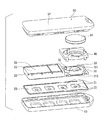
- FIG. 2 is an exploded perspective view illustrating the portable device
- FIG. 3 is a perspective view illustrating a circuit unit viewed from a knob sheet side
- FIG. 4 is a plan view illustrating a pair of opposite electrodes.
- FIG. 5A and FIG. 5B are perspective views illustrating a resin member in the circuit unit.
- a portable device 1 according to an exemplary embodiment of the invention can be suitably used as a portable electronic key, i.e., a smart key.
- identification data of the portable device 1 is verified with identification data of a vehicle by a two-way communication, and then each door of the vehicle can be locked and unlocked by using the portable device 1 .
- a steering lock mechanism can be unlocked and an engine can be started by using the portable device 1 .
- the portable device 1 includes a case body including a front case 10 and a rear case 50 .
- the front case 10 has a plurality of opening portions.
- a plurality of knob pieces 21 is disposed at the plurality of opening portions respectively.
- the front case 10 may be made of resin such as polycarbonate resin, acrylonitrile-butadiene-styrene resin (ABS resin), and polyamide resin
- the rear case 50 may be made of resin similar to the resin of the front case 10 .
- elastomer layer 51 is integrally formed with the rear case 50 .
- the elastomer layer 51 is an elastic sheet made of thermoplastic elastomer resin.
- the case body has a through hole as a key ring hole, for example.
- Each knob piece 21 is provided for controlling one of a door lock/unlock function, a trunk open function, a power slide door open/close function, a power back door open/close function, and a panic response function, for example.
- the panic response function is a function for activating an emergency response operation of the vehicle when the vehicle is involved in a criminal act or when the vehicle has a possibility of being involved in a criminal act.
- Each knob piece 21 an example of an operating part.
- a knob sheet 20 As illustrated in FIG. 2 , between the front case 10 and the rear case 50 , a knob sheet 20 , a circuit unit 30 , and battery holder 40 is arranged in this order from the front case side to the rear case side.
- Each of the knob sheet 20 and the circuit unit 30 has an approximately rectangular shape corresponding to a shape in the front case 10 and the rear case 50 .
- the battery holder 40 is configured to house a button battery 41 therein.
- the knob sheet 20 is made of silicon rubber for example.
- the knob pieces 21 are formed in the knob sheet 20 to be coupled to each other.
- a conductive contact 22 is integrally formed on a rear case side of each knob piece 21 .
- the conductive contacts 22 consist mainly of carbon, for example.
- the circuit unit 30 includes a printed circuit board 31 .
- the printed circuit board 31 has a first surface 311 arranged on the rear case side, a second surface 312 arranged on the front case side, and a side surface 313 extending from a peripheral edge of first surface 311 to a peripheral edge of the second surface 312 .
- a circuit section 32 is provided on the first surface side of the printed circuit board 31 .
- electronic elements including an antenna element are mounted on the first surface 311 .
- the circuit section 32 is configured to transmit a signal to an external device disposed in the vehicle.
- the pair of terminals 33 is an example of a terminal electrode for supplying electricity from the button battery 41 to the circuit section 32 .
- each opposite electrode 34 has a pectinate shape. That is, each opposite electrode 34 has a plurality of protruding portions. In each pair of opposite electrodes 34 , one opposite electrode 34 is separated from the other opposite electrode 34 and the protruding portions of the one opposite electrode 34 are alternately arranged with the protruding portions of the other opposite electrode 34 .
- Each conductive contact 22 is an example of a switch element and each pair of opposite electrodes 34 is an example of a pair of switch electrodes.
- Each of the terminals 33 and the opposite electrodes 34 has a surface plated with gold. Thereby, electric resistances of the surfaces can be reduced and the surfaces can be restricted from rusting. Thus, the pair of terminals 33 and the four pair of the opposite electrodes 34 can keep low electric resistances of the surfaces thereof.
- the circuit unit 30 is molded with a resin member 35 in such a manner that the whole circuit section 32 is covered with the resin member 35 , and the pair of terminals 33 and the four pair of opposite electrodes 34 are exposed to an outside of the resin member 35 .
- the resin member 35 is made of epoxy resin, for example.
- the resin member 35 covers an area of the first surface 311 other than an area having a shape corresponding to a shape of the button battery 41 and including the pair of terminals 33 .
- the resin member 35 covers the whole side surface 313 of the printed circuit board 31 .
- the whole second surface 312 of the printed circuit board 31 is not covered with the resin member 35 .
- the second surface 312 on which the electronic elements are not mounted, can closely come in contact with an inner surface of a cavity of a molding tool. Thereby, even if resin is filled into the cavity with a high pressure, the printed circuit board 31 is difficult to be warped and the resin member 35 can be firmly attached to the circuit section 32 .
- the circuit unit 30 the pair of terminals 33 and the four pairs of the opposite electrodes 34 are exposed to the outside of the resin member 35 and the circuit section 32 including the electronic elements is covered with the resin member 35 .
- the circuit section 32 can have a waterproof property without a waterproof cover including a ring-shaped part. As a result, a dimension of the case body of the portable device 1 can be reduced.
- the resin member 35 covers the side surface 313 in addition to the area of the first surface 311 where the circuit section 32 is provided. Thus, an adhesion of the resin member 35 with the printed circuit board 31 can be improved.
- each opposite electrode 34 has a plurality of protruding portions.
- one opposite electrode 34 is separated from the other opposite electrode 34 and the protruding portions of the one opposite electrode 34 are alternately arranged with the protruding portions of the other opposite electrode 34 .
- the corresponding conductive contact 22 comes in contact with and separates from the corresponding pair of opposite electrodes 34 . Thereby the electric switching can be controlled with a high degree of certainty.
- the conductive contacts 22 are integrally formed with the surfaces of the knob pieces 21 on the printed circuit board side. Thus, when one of the knob pieces 21 is operated, the corresponding conductive contact 22 comes in contact with and separates from the corresponding pair of opposite electrodes 34 with a high degree of certainty.
- the knob sheet 20 has a planar shape similar to a planar shape of the circuit unit 30 and is disposed in the front case 10 along an inner surface of the front case 10 .
- the elastomer layer 51 is integrally formed with the rear case 50 so as to cover the whole outer surface of the rear case 50 .
- the circuit unit 30 can be protected from a vibration and a drop impact by the knob sheet 20 and the elastomer layer 51 made of elastic sheets.
- the knob sheet 20 is held between the front case 10 and the circuit unit 30 , the knob sheet 20 is difficult to get out of position.
- the elastomer layer 51 is integrally formed with the rear case 50 , the elastomer layer 51 does not get out position with respect to the rear case 50 .
- resin is filled into the cavity of the molding tool and is solidified under pressure so that the resin member 35 covers the circuit section 32 .
- the resin member 35 may be formed by potting.
- a frame body is disposed to surround the circuit section 32 , and then resin is filled into the frame body and is solidified without applying pressure.
- the resin member 35 may be made of polyurethane resin, for example, without being limited to epoxy resin.
- the conductive contacts 22 may be made of various conductive materials without being limited to carbon.
- the conductive contacts 22 may be made of metal.
- each opposite electrode 34 has the pectinate shapes, as an example.
- each opposite electrode 34 may have other shape.
- one opposite electrode 34 is arranged to oppose the other opposite electrode 34 in each pair of opposite electrodes 34 in each pair of opposite electrodes 34 .
- the circuit unit 30 is protected by elastic sheets including the knob sheet 20 disposed along the inner surface of the front case 10 and the elastomer layer 51 integrally formed at an outer surface of the rear case 50 .
- the elastic sheet may be disposed one of an inner surface and an outer surface of the case body.
- the elastic sheet may be disposed along the inner surface of the case body on both sides of the circuit unit 30 .
- the portable device 1 is not limited to the portable electronic key (i.e., smart key) as illustrated in FIG. 1 .
- the portable device 1 may be other device that can transmit a signal to an external device.
- the portable device 1 may be a keyless transmitter for a keyless entry system.
Abstract
A portable device includes an operating part, a circuit board, and a case body for housing the operating part and the circuit board. The circuit board has a circuit section configured to transmit a signal to an external device. A terminal electrode and a pair of switch electrodes are disposed on the circuit board. The terminal electrode supplies electricity from a power source to the circuit section. A switch element is configured to electrically couple the pair of switch electrodes in accordance with an operation of the operating part. A resin member is disposed on the circuit board in such a manner that the circuit section is covered with the resin member and the terminal electrode and the pair of switch electrodes are exposed to an outside of the resin member.
Description
The present application is based on and claims priority to Japanese Patent Application No. 2007-205873 filed on Aug. 7, 2007, the contents of which are incorporated in their entirety herein by reference.
1. Field of the Invention
The present invention relates to a portable device for transmitting a signal.
2. Description of the Related Art
U.S. Pat. No. 7,050,292 (corresponding to JP-A-2004-153526) discloses a portable equipment that can be used for a keyless entry system. The portable equipment includes a circuit board, a button battery, and a case body for housing the circuit board and the button battery therein. The case body includes an upper case and a lower case. The circuit board has a circuit section that includes electronic elements. The circuit section is supplied with electricity from the button battery. At opening portions of the upper case, knob pieces are disposed so that switching elements disposed on the circuit board can be controlled by operating the knob pieces.
In the case body, a water-proof cover is disposed. The water-proof cover includes a thin-film cover and a ring-shaped part integrally formed at an outer peripheral portion of the thin-film cover. The ring-shaped part is held between the upper case and the lower case. The thin-film cover is disposed between the circuit board and the knob pieces.
In the above-described portable equipment, a pressing surface of the upper case and a pressing surface of the lower case that press the ring-shaped part of the water-proof cover are required to be formed with a high accuracy so as to provide a stable waterproof property of the circuit section. In addition, the upper case and the lower case are required to have a high rigidity to maintain the pressing surfaces formed with the high accuracy. Thus, a thickness of the upper case and a thickness of the lower case may increase, and thereby a dimension of the portable equipment may increase.
In view of the foregoing problems, it is an object of the present invention to provide a portable device including a waterproof circuit section.
According to an aspect of the invention, a portable device includes a case body, an operating part, a circuit board, a terminal electrode, a pair of switch electrodes, a switch element, and a resin member. The operating part is disposed in the case body. The circuit board is housed in the case body and has a circuit section. The circuit section includes an electronic element mounted on the circuit board and is configured to transmit a signal to an external device. The terminal electrode is disposed on the circuit board for supplying electricity from a power source to the circuit section. The pair of switch electrodes is disposed on the circuit board. The switch element is configured to electrically couple the pair of switch electrodes in accordance with an operation of the operating part. The resin member is disposed on the circuit board in such a manner that the circuit section is covered with the resin member and the terminal electrode and the pair of switch electrodes are exposed to an outside of the resin member.
The present portable device can ensure a waterproof property of the circuit section of the printed circuit board.
Additional objects and advantages of the present invention will be more readily apparent from the following detailed description of preferred embodiments when taken together with the accompanying drawings. In the drawings:
A portable device 1 according to an exemplary embodiment of the invention can be suitably used as a portable electronic key, i.e., a smart key. For example, identification data of the portable device 1 is verified with identification data of a vehicle by a two-way communication, and then each door of the vehicle can be locked and unlocked by using the portable device 1. In addition, when a passenger having the portable device 1 is in a vehicle compartment, a steering lock mechanism can be unlocked and an engine can be started by using the portable device 1.
As illustrated in FIG. 1 , the portable device 1 includes a case body including a front case 10 and a rear case 50. The front case 10 has a plurality of opening portions. A plurality of knob pieces 21 is disposed at the plurality of opening portions respectively.
The front case 10 may be made of resin such as polycarbonate resin, acrylonitrile-butadiene-styrene resin (ABS resin), and polyamide resin, The rear case 50 may be made of resin similar to the resin of the front case 10. On an outer surface of the rear case 50, elastomer layer 51 is integrally formed with the rear case 50. The elastomer layer 51 is an elastic sheet made of thermoplastic elastomer resin. The case body has a through hole as a key ring hole, for example.
In the portable device 1 illustrated in FIG. 1 , four knob pieces 21 are disposed. Each knob piece 21 is provided for controlling one of a door lock/unlock function, a trunk open function, a power slide door open/close function, a power back door open/close function, and a panic response function, for example. The panic response function is a function for activating an emergency response operation of the vehicle when the vehicle is involved in a criminal act or when the vehicle has a possibility of being involved in a criminal act. Each knob piece 21 an example of an operating part.
As illustrated in FIG. 2 , between the front case 10 and the rear case 50, a knob sheet 20, a circuit unit 30, and battery holder 40 is arranged in this order from the front case side to the rear case side. Each of the knob sheet 20 and the circuit unit 30 has an approximately rectangular shape corresponding to a shape in the front case 10 and the rear case 50. The battery holder 40 is configured to house a button battery 41 therein.
The knob sheet 20 is made of silicon rubber for example. The knob pieces 21 are formed in the knob sheet 20 to be coupled to each other. On a rear case side of each knob piece 21, a conductive contact 22 is integrally formed. The conductive contacts 22 consist mainly of carbon, for example.
The circuit unit 30 includes a printed circuit board 31. The printed circuit board 31 has a first surface 311 arranged on the rear case side, a second surface 312 arranged on the front case side, and a side surface 313 extending from a peripheral edge of first surface 311 to a peripheral edge of the second surface 312. On the first surface side of the printed circuit board 31, a circuit section 32 is provided. In the circuit section 32, electronic elements (not shown) including an antenna element are mounted on the first surface 311. The circuit section 32 is configured to transmit a signal to an external device disposed in the vehicle.
On the first surface 311 of the printed circuit board 31, a pair of terminals 33 is also disposed. The pair of terminals 33 is an example of a terminal electrode for supplying electricity from the button battery 41 to the circuit section 32.
As illustrated in FIG. 3 , on the second surface 312 of the printed circuit board 31, four pairs of opposite electrodes 34 are disposed to face the four conductive contacts 22 of the knob sheet 20, respectively. When one conductive contact 22 comes in contact with the corresponding pair of opposite electrodes 34, electric current flows between the pair of opposite electrodes 34. When the one conductive contact 22 separates from the pair of opposite electrodes 34, electric current does not flow between the pair of opposite electrodes 34. Thus, an electric switching is controlled when the conductive contact 22 comes in contact with and separates from the pair of the opposite electrodes 34.
As illustrated in FIG. 4 , each opposite electrode 34 has a pectinate shape. That is, each opposite electrode 34 has a plurality of protruding portions. In each pair of opposite electrodes 34, one opposite electrode 34 is separated from the other opposite electrode 34 and the protruding portions of the one opposite electrode 34 are alternately arranged with the protruding portions of the other opposite electrode 34. Each conductive contact 22 is an example of a switch element and each pair of opposite electrodes 34 is an example of a pair of switch electrodes.
Each of the terminals 33 and the opposite electrodes 34 has a surface plated with gold. Thereby, electric resistances of the surfaces can be reduced and the surfaces can be restricted from rusting. Thus, the pair of terminals 33 and the four pair of the opposite electrodes 34 can keep low electric resistances of the surfaces thereof.
The circuit unit 30 is molded with a resin member 35 in such a manner that the whole circuit section 32 is covered with the resin member 35, and the pair of terminals 33 and the four pair of opposite electrodes 34 are exposed to an outside of the resin member 35. The resin member 35 is made of epoxy resin, for example.
For example, as illustrated by the shaded area in FIG. 5A and FIG. 5B , the resin member 35 covers an area of the first surface 311 other than an area having a shape corresponding to a shape of the button battery 41 and including the pair of terminals 33. In addition, the resin member 35 covers the whole side surface 313 of the printed circuit board 31.
The whole second surface 312 of the printed circuit board 31 is not covered with the resin member 35. Thus, when the circuit section 32 including the electronic elements is molded with resin, the second surface 312, on which the electronic elements are not mounted, can closely come in contact with an inner surface of a cavity of a molding tool. Thereby, even if resin is filled into the cavity with a high pressure, the printed circuit board 31 is difficult to be warped and the resin member 35 can be firmly attached to the circuit section 32.
In the circuit unit 30, the pair of terminals 33 and the four pairs of the opposite electrodes 34 are exposed to the outside of the resin member 35 and the circuit section 32 including the electronic elements is covered with the resin member 35. Thus, the circuit section 32 can have a waterproof property without a waterproof cover including a ring-shaped part. As a result, a dimension of the case body of the portable device 1 can be reduced.
The resin member 35 covers the side surface 313 in addition to the area of the first surface 311 where the circuit section 32 is provided. Thus, an adhesion of the resin member 35 with the printed circuit board 31 can be improved.
As described above, each opposite electrode 34 has a plurality of protruding portions. In each pair of opposite electrodes 34, one opposite electrode 34 is separated from the other opposite electrode 34 and the protruding portions of the one opposite electrode 34 are alternately arranged with the protruding portions of the other opposite electrode 34. In accordance with an operation of one of the knob pieces 21, the corresponding conductive contact 22 comes in contact with and separates from the corresponding pair of opposite electrodes 34. Thereby the electric switching can be controlled with a high degree of certainty.
The conductive contacts 22 are integrally formed with the surfaces of the knob pieces 21 on the printed circuit board side. Thus, when one of the knob pieces 21 is operated, the corresponding conductive contact 22 comes in contact with and separates from the corresponding pair of opposite electrodes 34 with a high degree of certainty.
The knob sheet 20 has a planar shape similar to a planar shape of the circuit unit 30 and is disposed in the front case 10 along an inner surface of the front case 10. The elastomer layer 51 is integrally formed with the rear case 50 so as to cover the whole outer surface of the rear case 50. The circuit unit 30 can be protected from a vibration and a drop impact by the knob sheet 20 and the elastomer layer 51 made of elastic sheets.
Because the knob sheet 20 is held between the front case 10 and the circuit unit 30, the knob sheet 20 is difficult to get out of position. In addition, because the elastomer layer 51 is integrally formed with the rear case 50, the elastomer layer 51 does not get out position with respect to the rear case 50.
Although the present invention has been fully described in connection with the exemplary embodiments thereof with reference to the accompanying drawings, it is to be noted that various changes and modifications will become apparent to those skilled in the art.
In the above-described exemplary embodiment, resin is filled into the cavity of the molding tool and is solidified under pressure so that the resin member 35 covers the circuit section 32. Alternatively, the resin member 35 may be formed by potting. In the present case, a frame body is disposed to surround the circuit section 32, and then resin is filled into the frame body and is solidified without applying pressure.
The resin member 35 may be made of polyurethane resin, for example, without being limited to epoxy resin.
The conductive contacts 22 may be made of various conductive materials without being limited to carbon. For example, the conductive contacts 22 may be made of metal.
In the above-described exemplary embodiment, each opposite electrode 34 has the pectinate shapes, as an example. Alternatively, each opposite electrode 34 may have other shape. Also in the present case, in each pair of opposite electrodes 34, one opposite electrode 34 is arranged to oppose the other opposite electrode 34.
In the above-described exemplary embodiment, the circuit unit 30 is protected by elastic sheets including the knob sheet 20 disposed along the inner surface of the front case 10 and the elastomer layer 51 integrally formed at an outer surface of the rear case 50. Alternatively, the elastic sheet may be disposed one of an inner surface and an outer surface of the case body. For example, the elastic sheet may be disposed along the inner surface of the case body on both sides of the circuit unit 30.
The portable device 1 is not limited to the portable electronic key (i.e., smart key) as illustrated in FIG. 1 . Alternatively, the portable device 1 may be other device that can transmit a signal to an external device. For example, the portable device 1 may be a keyless transmitter for a keyless entry system.
Such changes and modifications are to be understood as being within the scope of the present invention as defined by the appended claims.
Claims (16)
1. A portable device comprising:
a case body;
an operating part disposed in the case body;
a circuit board housed in the case body and having a circuit section, the circuit section including an electronic element mounted on the circuit board, and the circuit section configured to transmit a signal to an external device;
a battery holder disposed on the circuit board and configured to house a button battery;
a terminal electrode disposed on the circuit board for supplying electricity from the button battery to the circuit section;
a pair of switch electrodes disposed on the circuit board;
a switch element configured to electrically couple the pair of switch electrodes in accordance with an operation of the operating part; and
a resin member disposed on the circuit board in such a manner that the circuit section is covered with the resin member, whereas the battery holder, the terminal electrode and the pair of switch electrodes are not covered with the resin member and are exposed to an outside of the resin member, wherein
the battery holder is a distinct and separate component from the resin member.
2. The portable device according to claim 1 , wherein:
the circuit board has a first surface and a second surface opposing the first surface;
the electronic element is mounted on the first surface;
the first surface is covered with the resin member; and
the second surface is exposed to the outside of the resin member.
3. The portable device according to claim 2 , wherein:
the circuit board further has a side surface extending from a peripheral edge of the first surface to a peripheral edge of the second surface; and
the resin member covers the first surface and the side surface.
4. The portable device according to claim 1 , wherein
each of the terminal electrode and the pair of switch electrodes has a surface plated with gold.
5. The portable device according to claim 1 , wherein:
one of the switch electrodes is separated from the other switch electrode;
the switch element is made of conductive material; and
the switch element is capable of coming in contact with and separating from the pair of switch electrodes.
6. The portable device according to claim 5 , wherein:
each of the switch electrodes has a plurality of protruding portions; and
the plurality of protruding portions of the one switch electrode is alternately arranged with the plurality of protruding portions of the other switch electrode.
7. The portable device according to claim 5 , wherein:
the operating part is made of a flexible sheet; and
the switch element is integrally disposed on a surface of the flexible sheet opposed to the circuit board.
8. The portable device according to claim 1 , further comprising
an elastic sheet disposed on one of an inner surface and an outer surface of the case body.
9. The portable device according to claim 8 , wherein
the elastic sheet is integrally formed with the case body.
10. The portable device according to claim 1 , wherein
the external device is disposed in a vehicle.
11. The portable device according to claim 1 , wherein
there are a plurality of operating parts, and
the case body includes a front case and a rear case, the front case having a plurality of opening portions, each corresponding to a respective said operating part.
12. The portable device according to claim 11 , wherein
said operating parts are carried by a support member sheet disposed within said case body, adjacent the front case.
13. The portable device according to claim 1 , wherein
the support member sheet is held between the front case and the circuit unit.
14. The portable device according to claim 1 , wherein
an elastomer layer is integrally formed with the rear case so as to cover an entire outer surface of the rear case.
15. The portable device according to claim 1 , wherein
the battery holder is disposed adjacent one longitudinal end of the circuit board and said circuit section is longitudinally spaced from the battery holder, so that the circuit section is disposed next to a portion of the circuit board on which the battery holder is disposed.
16. The portable device according to claim 1 , wherein
the resin member covers an area of a first surface of the circuit board other than an area having a shape corresponding to a shape of the button battery and the resin member covers an entire side surface of the printed circuit board, whereas an entire second surface of the printed circuit board, opposite said first surface, is not covered with the resin member.
Applications Claiming Priority (2)
| Application Number | Priority Date | Filing Date | Title |
|---|---|---|---|
| JP2007-205873 | 2007-08-07 | ||
| JP2007205873A JP4470971B2 (en) | 2007-08-07 | 2007-08-07 | Portable machine |
Publications (2)
| Publication Number | Publication Date |
|---|---|
| US20090040737A1 US20090040737A1 (en) | 2009-02-12 |
| US8072766B2 true US8072766B2 (en) | 2011-12-06 |
Family
ID=40346301
Family Applications (1)
| Application Number | Title | Priority Date | Filing Date |
|---|---|---|---|
| US12/175,860 Expired - Fee Related US8072766B2 (en) | 2007-08-07 | 2008-07-18 | Portable device for transmitting signal |
Country Status (3)
| Country | Link |
|---|---|
| US (1) | US8072766B2 (en) |
| JP (1) | JP4470971B2 (en) |
| DE (1) | DE102008035745A1 (en) |
Cited By (6)
| Publication number | Priority date | Publication date | Assignee | Title |
|---|---|---|---|---|
| US8953331B2 (en) | 2011-08-10 | 2015-02-10 | Denso Corporation | Card key |
| USD765609S1 (en) * | 2015-08-25 | 2016-09-06 | Panasonic Intellectual Property Management Co., Ltd. | Remote controller |
| USD773406S1 (en) * | 2015-02-03 | 2016-12-06 | Lg Electronics Inc. | Smart key for automobiles |
| US20180017242A1 (en) * | 2016-07-12 | 2018-01-18 | Abl Ip Holding Llc | Wall mounted battery-powered wireless device |
| US20180190442A1 (en) * | 2016-12-29 | 2018-07-05 | EnDimensions Korea Co., Ltd. | Detachable switch |
| US10658131B2 (en) * | 2015-03-20 | 2020-05-19 | Somfy Activites Sa | Remote-control device comprising a portable remote control and a wall mounting |
Families Citing this family (21)
| Publication number | Priority date | Publication date | Assignee | Title |
|---|---|---|---|---|
| US8289722B2 (en) * | 2009-04-02 | 2012-10-16 | Sony Computer Entertainment Inc. | Electronic apparatus |
| TWM375992U (en) * | 2009-09-25 | 2010-03-11 | Askey Computer Corp | Fixing structure of battery |
| DE102012102482A1 (en) * | 2012-03-22 | 2013-09-26 | Huf Hülsbeck & Fürst Gmbh & Co. Kg | Electronic key with a battery holder |
| US10137861B2 (en) * | 2013-10-07 | 2018-11-27 | Seoyon Electronics Co., Ltd. | Slim-type smart card key of vehicle and control method therefor |
| JP6315276B2 (en) * | 2014-11-19 | 2018-04-25 | 株式会社デンソー | Portable machine |
| JP6341570B2 (en) * | 2014-12-26 | 2018-06-13 | アルプス電気株式会社 | Portable machine |
| US9732963B2 (en) * | 2015-06-17 | 2017-08-15 | Haier Us Appliance Solutions, Inc. | Appliance control panel assembly |
| US11419231B1 (en) * | 2016-09-22 | 2022-08-16 | Apple Inc. | Forming glass covers for electronic devices |
| US11565506B2 (en) | 2016-09-23 | 2023-01-31 | Apple Inc. | Thermoformed cover glass for an electronic device |
| US11535551B2 (en) | 2016-09-23 | 2022-12-27 | Apple Inc. | Thermoformed cover glass for an electronic device |
| US10800141B2 (en) | 2016-09-23 | 2020-10-13 | Apple Inc. | Electronic device having a glass component with crack hindering internal stress regions |
| US11066322B2 (en) | 2017-12-01 | 2021-07-20 | Apple Inc. | Selectively heat-treated glass-ceramic for an electronic device |
| JP6855407B2 (en) * | 2018-03-28 | 2021-04-07 | 株式会社ファルテック | Vehicle electronic key |
| US11420900B2 (en) | 2018-09-26 | 2022-08-23 | Apple Inc. | Localized control of bulk material properties |
| US11680010B2 (en) | 2019-07-09 | 2023-06-20 | Apple Inc. | Evaluation of transparent components for electronic devices |
| CN115955798A (en) | 2020-03-28 | 2023-04-11 | 苹果公司 | Glass cover member for electronic device housing |
| US11460892B2 (en) | 2020-03-28 | 2022-10-04 | Apple Inc. | Glass cover member for an electronic device enclosure |
| US11666273B2 (en) | 2020-05-20 | 2023-06-06 | Apple Inc. | Electronic device enclosure including a glass ceramic region |
| USD991195S1 (en) * | 2020-06-05 | 2023-07-04 | Autel Intelligent Technology Corp., Ltd. | Smart key of vehicle |
| CN116783152A (en) | 2020-12-23 | 2023-09-19 | 苹果公司 | Laser-based cutting of transparent parts for electronic devices |
| USD1020664S1 (en) * | 2020-12-29 | 2024-04-02 | Autel Intelligent Technology Corp., Ltd. | Intelligent key of vehicle |
Citations (54)
| Publication number | Priority date | Publication date | Assignee | Title |
|---|---|---|---|---|
| US4158230A (en) * | 1976-10-15 | 1979-06-12 | Sharp Kabushiki Kaisha | Electronic calculator with no protruding key tops |
| US4635354A (en) * | 1982-07-22 | 1987-01-13 | Texas Instruments Incorporated | Low cost electronic apparatus construction method |
| US4681987A (en) * | 1983-01-11 | 1987-07-21 | Canon Kabushiki Kaisha | Electronic equipment having a key input function |
| JPS62290024A (en) | 1986-06-09 | 1987-12-16 | 信越ポリマ−株式会社 | Push button switch |
| US4801768A (en) * | 1984-08-07 | 1989-01-31 | Casio Computer Co., Ltd. | Compact electronic device |
| US4864115A (en) * | 1986-08-22 | 1989-09-05 | Datatrak, Inc. | Electronic access card having key pads and coils and combination using the same |
| US4876441A (en) * | 1984-03-27 | 1989-10-24 | Casio Computer Co., Ltd. | Card-like electronic apparatus |
| US5038251A (en) * | 1987-04-08 | 1991-08-06 | Casio Computer Co., Ltd. | Electronic apparatus and a method for manufacturing the same |
| US5291193A (en) * | 1988-01-21 | 1994-03-01 | Matsushita Electric Works, Ltd. | Identification registration for a wireless transmission-reception control system |
| JPH06268548A (en) | 1993-03-15 | 1994-09-22 | Hitachi Ltd | Case provided with water-proof function and portable telephone set |
| US5422783A (en) * | 1992-07-06 | 1995-06-06 | Universal Electronics Inc. | Modular casing for a remote control having upper housing member slidingly received in a panel section |
| US5523745A (en) * | 1988-12-16 | 1996-06-04 | Zofcom Systems, Inc. | Tongue activated communications controller |
| US5654111A (en) * | 1994-06-28 | 1997-08-05 | Sony Corporation | Electronic device having a battery and a battery therefor |
| US5782867A (en) * | 1995-06-01 | 1998-07-21 | Jasb, Inc. | Diaphragm switch |
| US5805423A (en) * | 1996-05-17 | 1998-09-08 | United Technologies Automotive | Battery contact and retention apparatus for printed circuit boards |
| JPH11280313A (en) | 1998-01-29 | 1999-10-12 | Alpha Corp | Electronic key |
| US6137710A (en) * | 1997-02-28 | 2000-10-24 | Kabushiki Kaisha Toshiba | Connecting apparatus, and information processing apparatus |
| US6172431B1 (en) * | 1999-05-18 | 2001-01-09 | Ewen Honeyman | Vehicle entry transmitter with conformable switch tip |
| US6262886B1 (en) * | 1999-09-30 | 2001-07-17 | Apple Computer, Inc. | Translucent protective covering for a computer housing |
| US6282819B1 (en) * | 1996-06-10 | 2001-09-04 | Jing Lu Gu | Design and manufacture of communicating card |
| US6349824B1 (en) * | 1998-06-26 | 2002-02-26 | Asahi Research Corporation | Watertight equipment cover |
| US6377465B1 (en) * | 1999-01-14 | 2002-04-23 | Nec Corporation | Printing wiring board |
| US6463263B1 (en) * | 1999-02-01 | 2002-10-08 | Telefonaktiebolaget Lm Ericsson (Publ) | Communication station |
| JP2002343905A (en) | 2001-05-11 | 2002-11-29 | Sansha Electric Mfg Co Ltd | Resin-molded circuit device |
| US20030010721A1 (en) * | 1998-03-04 | 2003-01-16 | Jeff Aldred | Filter faucet |
| US6546435B1 (en) * | 1999-06-15 | 2003-04-08 | Matsushita Electric Works, Ltd. | Portable programming device for supervisory remote control system |
| US6545233B2 (en) * | 2001-03-06 | 2003-04-08 | Alps Electric Co., Ltd. | Four-direction switch device |
| US6733327B2 (en) | 2002-08-23 | 2004-05-11 | Denso Corporation | Connector for button battery contained in electronic device |
| JP2004153526A (en) | 2002-10-30 | 2004-05-27 | Denso Corp | Case of cellular phone |
| JP2004172176A (en) | 2002-11-18 | 2004-06-17 | Taiyo Yuden Co Ltd | Circuit module |
| US6849817B2 (en) * | 2003-05-16 | 2005-02-01 | Alps Electric Co., Ltd. | Switching device including stopper surface-mounted on printed circuit board |
| US20050052128A1 (en) * | 2003-09-08 | 2005-03-10 | Polymatech Co. Ltd. | Light emitting electronic component |
| US20050060064A1 (en) * | 2001-10-01 | 2005-03-17 | Roald Valen | Industrial robot system comprising a programmable unit |
| US20050136852A1 (en) * | 2003-12-17 | 2005-06-23 | Denso Corporation | Wireless transceiver for automotive vehicle |
| US20050181843A1 (en) * | 2004-02-18 | 2005-08-18 | Nec Corporation | Portable telephone and method of manufacturing the same |
| US20060066151A1 (en) * | 2004-09-22 | 2006-03-30 | Matsushita Electric Works, Ltd. | Setting device of control system |
| US7067734B2 (en) * | 2003-06-06 | 2006-06-27 | Kabushiki Kaisha Toshiba | Cable modem module and transmitter-receiver |
| US20060245145A1 (en) | 2005-04-28 | 2006-11-02 | Denso Corporation | Wireless communicating apparatus and production method therefor |
| US7142413B2 (en) * | 2003-04-10 | 2006-11-28 | Denso Corporation | Portable transmitter having space for containing mechanical key |
| US20070066394A1 (en) * | 2005-09-15 | 2007-03-22 | Nintendo Co., Ltd. | Video game system with wireless modular handheld controller |
| US7201310B2 (en) * | 2005-04-15 | 2007-04-10 | Matsushita Electric Works, Ltd. | Setting apparatus for remote monitoring and controlling system |
| US7225972B2 (en) * | 2004-07-27 | 2007-06-05 | Matsushita Electric Works, Ltd. | Setting apparatus for remote monitoring and control system |
| US20070200053A1 (en) * | 2006-02-02 | 2007-08-30 | Sony Corporation | Image pickup apparatus, camera module, electronic device, and fabrication method for image pickup apparatus |
| US7271423B2 (en) * | 2000-09-21 | 2007-09-18 | Sharp Kabushiki Kaisha | Semiconductor light-emitting device and light-emitting display device therewith |
| US20070223317A1 (en) * | 2006-03-25 | 2007-09-27 | Hon Hai Precision Industry Co., Ltd. | Printed circuit board having battery holder |
| US7330743B2 (en) * | 2000-12-29 | 2008-02-12 | Vertu Limited | Casing |
| US7355137B2 (en) * | 2005-06-09 | 2008-04-08 | Casio Hitachi Mobile Communications Co., Ltd. | Waterproof structure of push button switch |
| US20080084403A1 (en) * | 2005-05-02 | 2008-04-10 | Semiconductor Energy Laboratory Co., Ltd. | Method for driving display device |
| US7445476B2 (en) * | 2004-09-02 | 2008-11-04 | Kyocera Corporation | Card for information equipment, and terminal for information equipment |
| US7463134B1 (en) * | 2005-04-01 | 2008-12-09 | Stilley Russell L | Dual key fob |
| US7519404B2 (en) * | 1998-03-18 | 2009-04-14 | Nokia Corporation | Telescopic telephone |
| US7561684B2 (en) * | 2005-03-18 | 2009-07-14 | Casio Hitachi Mobile Communications Co., Ltd. | Mounting structure for an electroacoustic transducer |
| US7635821B2 (en) * | 2006-04-03 | 2009-12-22 | Funai Electric Co., Ltd. | Remote controller |
| US20100048249A1 (en) * | 2006-01-30 | 2010-02-25 | Kyocera Corporation | Display Holder, Portable Electronic Apparatus, and Assembling Method of Display Holder |
-
2007
- 2007-08-07 JP JP2007205873A patent/JP4470971B2/en active Active
-
2008
- 2008-07-18 US US12/175,860 patent/US8072766B2/en not_active Expired - Fee Related
- 2008-07-31 DE DE200810035745 patent/DE102008035745A1/en not_active Withdrawn
Patent Citations (55)
| Publication number | Priority date | Publication date | Assignee | Title |
|---|---|---|---|---|
| US4158230A (en) * | 1976-10-15 | 1979-06-12 | Sharp Kabushiki Kaisha | Electronic calculator with no protruding key tops |
| US4635354A (en) * | 1982-07-22 | 1987-01-13 | Texas Instruments Incorporated | Low cost electronic apparatus construction method |
| US4681987A (en) * | 1983-01-11 | 1987-07-21 | Canon Kabushiki Kaisha | Electronic equipment having a key input function |
| US4876441A (en) * | 1984-03-27 | 1989-10-24 | Casio Computer Co., Ltd. | Card-like electronic apparatus |
| US4801768A (en) * | 1984-08-07 | 1989-01-31 | Casio Computer Co., Ltd. | Compact electronic device |
| JPS62290024A (en) | 1986-06-09 | 1987-12-16 | 信越ポリマ−株式会社 | Push button switch |
| US4864115A (en) * | 1986-08-22 | 1989-09-05 | Datatrak, Inc. | Electronic access card having key pads and coils and combination using the same |
| US5038251A (en) * | 1987-04-08 | 1991-08-06 | Casio Computer Co., Ltd. | Electronic apparatus and a method for manufacturing the same |
| US5291193A (en) * | 1988-01-21 | 1994-03-01 | Matsushita Electric Works, Ltd. | Identification registration for a wireless transmission-reception control system |
| US5523745A (en) * | 1988-12-16 | 1996-06-04 | Zofcom Systems, Inc. | Tongue activated communications controller |
| US5422783A (en) * | 1992-07-06 | 1995-06-06 | Universal Electronics Inc. | Modular casing for a remote control having upper housing member slidingly received in a panel section |
| JPH06268548A (en) | 1993-03-15 | 1994-09-22 | Hitachi Ltd | Case provided with water-proof function and portable telephone set |
| US5654111A (en) * | 1994-06-28 | 1997-08-05 | Sony Corporation | Electronic device having a battery and a battery therefor |
| US5782867A (en) * | 1995-06-01 | 1998-07-21 | Jasb, Inc. | Diaphragm switch |
| US5805423A (en) * | 1996-05-17 | 1998-09-08 | United Technologies Automotive | Battery contact and retention apparatus for printed circuit boards |
| US6282819B1 (en) * | 1996-06-10 | 2001-09-04 | Jing Lu Gu | Design and manufacture of communicating card |
| US6137710A (en) * | 1997-02-28 | 2000-10-24 | Kabushiki Kaisha Toshiba | Connecting apparatus, and information processing apparatus |
| JPH11280313A (en) | 1998-01-29 | 1999-10-12 | Alpha Corp | Electronic key |
| US20030010721A1 (en) * | 1998-03-04 | 2003-01-16 | Jeff Aldred | Filter faucet |
| US7519404B2 (en) * | 1998-03-18 | 2009-04-14 | Nokia Corporation | Telescopic telephone |
| US6349824B1 (en) * | 1998-06-26 | 2002-02-26 | Asahi Research Corporation | Watertight equipment cover |
| US6377465B1 (en) * | 1999-01-14 | 2002-04-23 | Nec Corporation | Printing wiring board |
| US6463263B1 (en) * | 1999-02-01 | 2002-10-08 | Telefonaktiebolaget Lm Ericsson (Publ) | Communication station |
| US6172431B1 (en) * | 1999-05-18 | 2001-01-09 | Ewen Honeyman | Vehicle entry transmitter with conformable switch tip |
| US6546435B1 (en) * | 1999-06-15 | 2003-04-08 | Matsushita Electric Works, Ltd. | Portable programming device for supervisory remote control system |
| US6262886B1 (en) * | 1999-09-30 | 2001-07-17 | Apple Computer, Inc. | Translucent protective covering for a computer housing |
| US7271423B2 (en) * | 2000-09-21 | 2007-09-18 | Sharp Kabushiki Kaisha | Semiconductor light-emitting device and light-emitting display device therewith |
| US7330743B2 (en) * | 2000-12-29 | 2008-02-12 | Vertu Limited | Casing |
| US6545233B2 (en) * | 2001-03-06 | 2003-04-08 | Alps Electric Co., Ltd. | Four-direction switch device |
| JP2002343905A (en) | 2001-05-11 | 2002-11-29 | Sansha Electric Mfg Co Ltd | Resin-molded circuit device |
| US20050060064A1 (en) * | 2001-10-01 | 2005-03-17 | Roald Valen | Industrial robot system comprising a programmable unit |
| US6733327B2 (en) | 2002-08-23 | 2004-05-11 | Denso Corporation | Connector for button battery contained in electronic device |
| JP2004153526A (en) | 2002-10-30 | 2004-05-27 | Denso Corp | Case of cellular phone |
| US7050292B2 (en) | 2002-10-30 | 2006-05-23 | Denso Corporation | Case for portable equipment |
| JP2004172176A (en) | 2002-11-18 | 2004-06-17 | Taiyo Yuden Co Ltd | Circuit module |
| US7142413B2 (en) * | 2003-04-10 | 2006-11-28 | Denso Corporation | Portable transmitter having space for containing mechanical key |
| US6849817B2 (en) * | 2003-05-16 | 2005-02-01 | Alps Electric Co., Ltd. | Switching device including stopper surface-mounted on printed circuit board |
| US7067734B2 (en) * | 2003-06-06 | 2006-06-27 | Kabushiki Kaisha Toshiba | Cable modem module and transmitter-receiver |
| US20050052128A1 (en) * | 2003-09-08 | 2005-03-10 | Polymatech Co. Ltd. | Light emitting electronic component |
| US20050136852A1 (en) * | 2003-12-17 | 2005-06-23 | Denso Corporation | Wireless transceiver for automotive vehicle |
| US20050181843A1 (en) * | 2004-02-18 | 2005-08-18 | Nec Corporation | Portable telephone and method of manufacturing the same |
| US7225972B2 (en) * | 2004-07-27 | 2007-06-05 | Matsushita Electric Works, Ltd. | Setting apparatus for remote monitoring and control system |
| US7445476B2 (en) * | 2004-09-02 | 2008-11-04 | Kyocera Corporation | Card for information equipment, and terminal for information equipment |
| US20060066151A1 (en) * | 2004-09-22 | 2006-03-30 | Matsushita Electric Works, Ltd. | Setting device of control system |
| US7561684B2 (en) * | 2005-03-18 | 2009-07-14 | Casio Hitachi Mobile Communications Co., Ltd. | Mounting structure for an electroacoustic transducer |
| US7463134B1 (en) * | 2005-04-01 | 2008-12-09 | Stilley Russell L | Dual key fob |
| US7201310B2 (en) * | 2005-04-15 | 2007-04-10 | Matsushita Electric Works, Ltd. | Setting apparatus for remote monitoring and controlling system |
| US20060245145A1 (en) | 2005-04-28 | 2006-11-02 | Denso Corporation | Wireless communicating apparatus and production method therefor |
| US20080084403A1 (en) * | 2005-05-02 | 2008-04-10 | Semiconductor Energy Laboratory Co., Ltd. | Method for driving display device |
| US7355137B2 (en) * | 2005-06-09 | 2008-04-08 | Casio Hitachi Mobile Communications Co., Ltd. | Waterproof structure of push button switch |
| US20070066394A1 (en) * | 2005-09-15 | 2007-03-22 | Nintendo Co., Ltd. | Video game system with wireless modular handheld controller |
| US20100048249A1 (en) * | 2006-01-30 | 2010-02-25 | Kyocera Corporation | Display Holder, Portable Electronic Apparatus, and Assembling Method of Display Holder |
| US20070200053A1 (en) * | 2006-02-02 | 2007-08-30 | Sony Corporation | Image pickup apparatus, camera module, electronic device, and fabrication method for image pickup apparatus |
| US20070223317A1 (en) * | 2006-03-25 | 2007-09-27 | Hon Hai Precision Industry Co., Ltd. | Printed circuit board having battery holder |
| US7635821B2 (en) * | 2006-04-03 | 2009-12-22 | Funai Electric Co., Ltd. | Remote controller |
Non-Patent Citations (1)
| Title |
|---|
| Japanese Office Action dated Sep. 15, 2009, issued in corresponding Japanese Application No. 2007-205873, with English translation. |
Cited By (8)
| Publication number | Priority date | Publication date | Assignee | Title |
|---|---|---|---|---|
| US8953331B2 (en) | 2011-08-10 | 2015-02-10 | Denso Corporation | Card key |
| USD773406S1 (en) * | 2015-02-03 | 2016-12-06 | Lg Electronics Inc. | Smart key for automobiles |
| US10658131B2 (en) * | 2015-03-20 | 2020-05-19 | Somfy Activites Sa | Remote-control device comprising a portable remote control and a wall mounting |
| USD765609S1 (en) * | 2015-08-25 | 2016-09-06 | Panasonic Intellectual Property Management Co., Ltd. | Remote controller |
| US20180017242A1 (en) * | 2016-07-12 | 2018-01-18 | Abl Ip Holding Llc | Wall mounted battery-powered wireless device |
| US10066820B2 (en) * | 2016-07-12 | 2018-09-04 | Abl Ip Holding Llc | Wall mounted battery-powered wireless device |
| US20180190442A1 (en) * | 2016-12-29 | 2018-07-05 | EnDimensions Korea Co., Ltd. | Detachable switch |
| US10574037B2 (en) * | 2016-12-29 | 2020-02-25 | EnDimensions Korea Co., Ltd. | Detachable switch |
Also Published As
| Publication number | Publication date |
|---|---|
| JP2009044351A (en) | 2009-02-26 |
| US20090040737A1 (en) | 2009-02-12 |
| DE102008035745A1 (en) | 2009-03-19 |
| JP4470971B2 (en) | 2010-06-02 |
Similar Documents
| Publication | Publication Date | Title |
|---|---|---|
| US8072766B2 (en) | Portable device for transmitting signal | |
| US9959688B2 (en) | Portable wireless key | |
| US8294053B2 (en) | Electronic key | |
| US9894794B2 (en) | Portable wireless key | |
| KR100953597B1 (en) | Portable device having flexible case | |
| US20110241830A1 (en) | Portable transmitter | |
| US7499283B2 (en) | Key fob for an automobile | |
| US20060290468A1 (en) | Vehicle anti-theft system incorporated with internal antennas | |
| CN104640744A (en) | Door lock control system | |
| WO2016088643A1 (en) | Module and electronic key using module | |
| US6621446B1 (en) | Remote control unit | |
| US9076603B2 (en) | Switch packing and electronic key using the same | |
| JP4211471B2 (en) | Waterproof switch structure | |
| KR20140130530A (en) | Portable device for vehicle | |
| CN109154164B (en) | Portable device | |
| JP3897728B2 (en) | Vehicle door handle device | |
| CN116568479A (en) | Resin case with electronic component and method for manufacturing the same | |
| JP2002158519A (en) | Antenna for portable radio equipment | |
| JP4169901B2 (en) | Electronic code lock key | |
| JP2000124626A (en) | Transmitter structure | |
| JP2010077618A (en) | Electronic key | |
| KR101480388B1 (en) | Smart key assembly with film type switch | |
| JP2569741Y2 (en) | Keys with grips with built-in electronics | |
| KR101516375B1 (en) | Smart key assembly with film type switch at battery module | |
| KR101830256B1 (en) | Card type smart key |
Legal Events
| Date | Code | Title | Description |
|---|---|---|---|
| AS | Assignment |
Owner name: DENSO CORPORATION, JAPAN Free format text: ASSIGNMENT OF ASSIGNORS INTEREST;ASSIGNORS:SHIMURA, TOKIO;NAKAGAWA, MITSURU;REEL/FRAME:021258/0957 Effective date: 20080702 |
|
| FEPP | Fee payment procedure |
Free format text: PAYOR NUMBER ASSIGNED (ORIGINAL EVENT CODE: ASPN); ENTITY STATUS OF PATENT OWNER: LARGE ENTITY |
|
| REMI | Maintenance fee reminder mailed | ||
| LAPS | Lapse for failure to pay maintenance fees | ||
| STCH | Information on status: patent discontinuation |
Free format text: PATENT EXPIRED DUE TO NONPAYMENT OF MAINTENANCE FEES UNDER 37 CFR 1.362 |
|
| FP | Lapsed due to failure to pay maintenance fee |
Effective date: 20151206 |