US8078890B2 - System and method for providing memory performance states in a computing system - Google Patents
System and method for providing memory performance states in a computing system Download PDFInfo
- Publication number
- US8078890B2 US8078890B2 US11/853,255 US85325507A US8078890B2 US 8078890 B2 US8078890 B2 US 8078890B2 US 85325507 A US85325507 A US 85325507A US 8078890 B2 US8078890 B2 US 8078890B2
- Authority
- US
- United States
- Prior art keywords
- computing system
- memory
- memory performance
- performance state
- states
- Prior art date
- Legal status (The legal status is an assumption and is not a legal conclusion. Google has not performed a legal analysis and makes no representation as to the accuracy of the status listed.)
- Active, expires
Links
Images


Classifications
-
- G—PHYSICS
- G06—COMPUTING; CALCULATING OR COUNTING
- G06F—ELECTRIC DIGITAL DATA PROCESSING
- G06F1/00—Details not covered by groups G06F3/00 - G06F13/00 and G06F21/00
- G06F1/26—Power supply means, e.g. regulation thereof
- G06F1/32—Means for saving power
- G06F1/3203—Power management, i.e. event-based initiation of a power-saving mode
- G06F1/3234—Power saving characterised by the action undertaken
- G06F1/325—Power saving in peripheral device
- G06F1/3275—Power saving in memory, e.g. RAM, cache
-
- G—PHYSICS
- G06—COMPUTING; CALCULATING OR COUNTING
- G06F—ELECTRIC DIGITAL DATA PROCESSING
- G06F1/00—Details not covered by groups G06F3/00 - G06F13/00 and G06F21/00
- G06F1/26—Power supply means, e.g. regulation thereof
- G06F1/32—Means for saving power
- G06F1/3203—Power management, i.e. event-based initiation of a power-saving mode
- G06F1/3206—Monitoring of events, devices or parameters that trigger a change in power modality
- G06F1/3215—Monitoring of peripheral devices
- G06F1/3225—Monitoring of peripheral devices of memory devices
-
- Y—GENERAL TAGGING OF NEW TECHNOLOGICAL DEVELOPMENTS; GENERAL TAGGING OF CROSS-SECTIONAL TECHNOLOGIES SPANNING OVER SEVERAL SECTIONS OF THE IPC; TECHNICAL SUBJECTS COVERED BY FORMER USPC CROSS-REFERENCE ART COLLECTIONS [XRACs] AND DIGESTS
- Y02—TECHNOLOGIES OR APPLICATIONS FOR MITIGATION OR ADAPTATION AGAINST CLIMATE CHANGE
- Y02D—CLIMATE CHANGE MITIGATION TECHNOLOGIES IN INFORMATION AND COMMUNICATION TECHNOLOGIES [ICT], I.E. INFORMATION AND COMMUNICATION TECHNOLOGIES AIMING AT THE REDUCTION OF THEIR OWN ENERGY USE
- Y02D10/00—Energy efficient computing, e.g. low power processors, power management or thermal management
Definitions
- the present disclosure relates generally to computer systems and information handling systems, and, more particularly, to a system and method for providing preestablished memory performance states in a computing system to provide for reduced thermal output and power consumption.
- An information handling system generally processes, compiles, stores, and/or communicates information or data for business, personal, or other purposes thereby allowing users to take advantage of the value of the information. Because technology and information handling needs and requirements vary between different users or applications, information handling systems may vary with respect to the type of information handled; the methods for handling the information; the methods for processing, storing or communicating the information; the amount of information processed, stored, or communicated; and the speed and efficiency with which the information is processed, stored, or communicated.
- information handling systems allow for information handling systems to be general or configured for a specific user or specific use such as financial transaction processing, airline reservations, enterprise data storage, or global communications.
- information handling systems may include or comprise a variety of hardware and software components that may be configured to process, store, and communicate information and may include one or more computer systems, data storage systems, and networking systems.
- a computer system will generate heat. Unless heat is removed from the interior of a computer system, the components of the computer system may be damaged or the performance of the computer system could be negatively affected. Computer systems also consume power, which can be costly. The amount of power consumed by a computer system is related to the activity level of the computer system. The power consumption of a computer system may be considered excessive when the computer system consumes an amount of power that is not in proportion to the activity level of the computer system.
- a system and method for providing memory performance states in a computing system.
- the operating system power management component of the computing system establishes a set of performance states, with each performance state being defined by a number of factors, including the core frequency of memory.
- the operating system power management component also defines the number of memory performance states that are supported by the computing system and the number of supported memory performance states that are available for use by the computing system. Whether a supported memory performance state is available is dependent upon a measure of the power being consumed by the computing system, the thermal output of the computing system, or both measures.
- the system and method disclosed herein is technically advantageous in that it provides for distinct memory performance states. Some of the memory performance states may be characterized as lower performance state having a lower rate of power consumption and a lower thermal output. Thus, by transitioning to one of these lower performance states, the power consumed by the computing system and the thermal output of the computing system may be decreased. As such, the system and method disclosed herein provides an alternative to performance states that are premised on the operation of the processor of the computing system. In this environment, the processor could continue to operate normally while the performance state of the memory is controlled to manage the power consumption and thermal output of the computing system. The system and method disclosed herein is also advantageous because the operating system power management component can be used to control the memory performance states that are made available to the computing system.
- FIG. 1 is a diagram of hardware and software elements of a computer system
- FIG. 2 is a diagram of a hardware system of a computer system
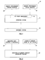
- FIG. 3 is a flow diagram of a method for calling the Memory Present Capabilities Routine.
- an information handling system may include any instrumentality or aggregate of instrumentalities operable to compute, classify, process, transmit, receive, retrieve, originate, switch, store, display, manifest, detect, record, reproduce, handle, or utilize any form of information, intelligence, or data for business, scientific, control, or other purposes.
- an information handling system may be a personal computer, a network storage device, or any other suitable device and may vary in size, shape, performance, functionality, and price.
- the information handling system may include random access memory (RAM), one or more processing resources such as a central processing unit (CPU) or hardware or software control logic, ROM, and/or other types of nonvolatile memory.
- Additional components of the information handling system may include one or more disk drives, one or more network ports for communication with external devices as well as various input and output (I/O) devices, such as a keyboard, a mouse, and a video display.
- the information handling system may also include one or more buses operable to transmit communications between the various hardware components.
- the system and method disclosed herein concerns memory performance states for a computing system. Multiple performance states are established, with each being associated with a different performance state for the memory of the computer system. As such, a performance state can be established for the memory of the computer system that corresponds to the activity level of the memory of the computer system. In this manner, and depending on the memory performance state of the computer system the heated generated by the computing system and the power consumed by the computing system may be reduced. Each performance state is associated with a level of power consumption in and the thermal output of the computer system.
- FIG. 1 Shown in FIG. 1 is a diagram of hardware and software elements of a computer system, which is indicated generally at 10 .
- Computer system 10 includes a hardware layer 12 , which includes a processor, memory, and the other hardware elements of the computer system.
- An operating system 14 executes on the processor and other components of hardware system 12 .
- OSPM operating system power management component
- OSPM component 16 is the portion of the operating system 14 that controls, at an operating system level, the power management functions of the operating system, including transitioning the computer system between power management states.
- OSPM component 16 reads from and writes to two software registers: memory performance control register 20 and memory performance status register 18 .
- FIG. 2 A diagram of an example hardware system is shown in FIG. 2 .
- a processor or CPU 30 of an example computer system 10 is communicatively coupled to a memory controller hub 32 .
- Memory controller hub 32 is coupled to memory 34 and a graphics processing unit 36 .
- Memory controller hub 34 is also coupled to an I/O controller hub 35 .
- I/O hub 35 is coupled to storage elements of the computer system, including a storage element 40 for the BIOS of the computer system and the hard drive 42 of the computer system.
- I/O hub 34 may also be coupled to a Super I/O chip 44 , which is itself coupled to many of the I/O ports of the computer system, including keyboard 46 , mouse 48 , and parallel ports.
- some of the components of the computer system such as the memory controller hub 32 or hard drive 42 , may act as a bus master to directly access memory 34 .
- Memory performance control register 20 uniquely identifies the memory performance state of the computer system.
- Memory performance status register 18 includes a code that identifies whether the computer system has successfully transitioned between memory performance states.
- Each of memory performance control register 20 and memory performance status register 18 are virtual registers that may be defined as software objects in the OSPM.
- the content of the memory performance control register identifies the memory state of the computer system.
- the OSPM reads from and writes to the memory performance control register. When the OSPM wants to change the memory performance state of the computer system, the OSPM writes a new value to the memory performance control register. The new value will be the value associated with the memory performance state to which the computer system will transition.
- OSPM may also call a Memory Performance States Routine.
- the Memory Performance States Routine identifies the numbers of memory performance states that have been defined in the OSPM and returns that number to the calling routine within OSPM in the form of a value N.
- a value N indicates that there are a total of N+1 performance states are supported in the computer system and those performance states are numbered 0 through N.
- the 0th performance state is the highest performance state, which is characterized by the greatest amount of activity in the memory system.
- the Nth performance state is the lowest performance state, which is characterized as the lowest amount of activity in the memory system.
- each performance state is defined by a set number of variables. In one example, which is set out below, each performance state is defined by six variables:
- OSPM determines that it will transition from one defined memory performance state to a second defined memory performance state
- the OSPM will write the control value of the second defined memory performance state to the memory performance control register 20 .
- the OSPM will also write the status value of the second defined memory performance state to the memory performance status register 18 .
- a modification of the memory performance control register 20 causes the core frequency of the memory to the level associated with the second defined memory performance state.
- the computer system will run a test routine to identify if the computer system is in the second defined performance state. This test may evaluate the memory core frequency, among other factors, and return a value, which is compared to the status value of memory performance status register 18 .
- the transition process If the values match, the computer system has successfully transitioned to the second defined memory performance state. If the values do not match, the transition process enters a loop in which the computer system continues to reach the second defined memory performance state, as measured by the test routine. After a set number of tries, the transition process may time out and the computer system may return to the previous memory state.
- OSPM may also call a Memory Present Capabilities Routine, which identifies the memory states that are available to the OSPM.
- the result of the Memory Present Capabilities Routine is the number of memory performance states that are both supported and available in the computer system.
- OSPM will call the Memory Present Capabilities Routine (step 52 ).
- the result of the Memory Present Capabilities Routine is an integer value that sets a boundary for the number of states available.
- the Memory Present Capabilities Routine returns the value 2
- memory performance states 2 through N are available, where N is defined through the Memory Performance States Routine as the computer system supporting N+1 performance states.
- N is defined through the Memory Performance States Routine as the computer system supporting N+1 performance states.
- the two performance states associated with the highest performance or activity levels in the computer system are not supported.
- states 0 through N are available, which the result being that all of the supported memory performance states of the computer system are available. If the value N is returned, only the lowest performance of the memory states is available.
- the Memory Present Capabilities Routine can dynamically return a value of between 0 to N. As an example, if an excessive amount of heat is being generated, the Memory Present Capabilities Routine could return an N, which would limit the OSPM to only the lowest performance of the memory states. As a second example, if the Memory Present Capabilities Routine detects that the computer system is generating a relatively low level of heat, the Memory Present Capabilities Routine could generate a value of 0, indicating all of the supported memory states of the computer system are available. In this manner, the OSPM can govern the management of memory states by limiting the available memory states, depending on the amount of heat being generated by the computer system.
- the Memory Present Capabilities Routine can dynamically return a value of between 0 to N.
- Memory usage may be measured by a memory controller hub in the computer system.
- the Memory Present Capabilities Routine could return an N, which would limit the OSPM to only the lowest performance of the memory states, thereby matching the actual memory usage of the computer system.
- the Memory Present Capabilities Routine could generate a value of 0, indicating all of the supported memory states of the computer system are available, thereby providing the computer system with the necessary flexibility to choose a memory performance state that actually matches the memory usage of the computer system.
- the OSPM can manage the allocation of memory performance states to force the computer system to operate at a lower performance state when memory usage is at a low level.
- an algorithm may be developed that uses both a measure of heat generation and a measure of memory usage to allocate the number of available memory states.
- the algorithm could specify that, if the thermal output of the computer system is above a defined threshold, a value of N is returned by the Memory Present Capabilities Routine until the thermal output is below the threshold. In this manner, regardless of the memory usage of the computer system, the computer system is placed in a lower performance state until the thermal output of the computer system is below a predetermined.
- the memory usage of the computer system could be the sole governing factor that determines the number of memory performance states available in the computer system.
- the system and method disclosed herein described herein includes several advantages.
- the system and method provides a technique reducing power consumption and thermal output according by managing the memory states of the computer system.
- the system and method disclosed herein is not dependent on a particular architecture within the computer system. Rather, the system and method disclosed herein may be used with any computer system that includes memory, multiple memory states, and a method for managing the memory states.
Abstract
Description
-
- memory core frequency;
- typical power dissipation;
- memory transition latency;
- bus master transition latency;
- control value;
- status value;
Memory core frequency is expressed in hertz and is the frequency of the memory of the computer system. Typical power dissipation is expressed in milliwatts and describes the amount of power consumed by a typical, benchmarked computer system when in the defined performance state. Memory transition latency is expressed in microseconds and is a worst-case latency measure of the time during which the memory is unavailable during a transition from any other performance state to the defined performance state. During a period of memory transition latency, the memory will be in a self-refresh mode. Bus master transition latency is expressed in microseconds and is a worst-case latency measure of the time during which any bus master of the system is prevented from accessing the memory during a transition from any other performance state to the defined performance state. The control value is the value that is written to the memory performance control register 20 to indicate a transition to the defined state. Each defined state is uniquely identified with a control value for the purpose of identifying a transition to the state. Status value is a value that the OSPM will compare to the value of the memory performance status register to determine if the transition to the memory performance state was successful.
Claims (19)
Priority Applications (1)
| Application Number | Priority Date | Filing Date | Title |
|---|---|---|---|
| US11/853,255 US8078890B2 (en) | 2007-09-11 | 2007-09-11 | System and method for providing memory performance states in a computing system |
Applications Claiming Priority (1)
| Application Number | Priority Date | Filing Date | Title |
|---|---|---|---|
| US11/853,255 US8078890B2 (en) | 2007-09-11 | 2007-09-11 | System and method for providing memory performance states in a computing system |
Publications (2)
| Publication Number | Publication Date |
|---|---|
| US20090070605A1 US20090070605A1 (en) | 2009-03-12 |
| US8078890B2 true US8078890B2 (en) | 2011-12-13 |
Family
ID=40433130
Family Applications (1)
| Application Number | Title | Priority Date | Filing Date |
|---|---|---|---|
| US11/853,255 Active 2029-04-13 US8078890B2 (en) | 2007-09-11 | 2007-09-11 | System and method for providing memory performance states in a computing system |
Country Status (1)
| Country | Link |
|---|---|
| US (1) | US8078890B2 (en) |
Cited By (1)
| Publication number | Priority date | Publication date | Assignee | Title |
|---|---|---|---|---|
| US20110320846A1 (en) * | 2010-06-23 | 2011-12-29 | David Howard S | Adaptive memory frequency scaling |
Families Citing this family (9)
| Publication number | Priority date | Publication date | Assignee | Title |
|---|---|---|---|---|
| US8438410B2 (en) * | 2010-06-23 | 2013-05-07 | Intel Corporation | Memory power management via dynamic memory operation states |
| US8769316B2 (en) | 2011-09-06 | 2014-07-01 | Intel Corporation | Dynamically allocating a power budget over multiple domains of a processor |
| US8954770B2 (en) | 2011-09-28 | 2015-02-10 | Intel Corporation | Controlling temperature of multiple domains of a multi-domain processor using a cross domain margin |
| US9074947B2 (en) | 2011-09-28 | 2015-07-07 | Intel Corporation | Estimating temperature of a processor core in a low power state without thermal sensor information |
| US8832478B2 (en) | 2011-10-27 | 2014-09-09 | Intel Corporation | Enabling a non-core domain to control memory bandwidth in a processor |
| US9026815B2 (en) | 2011-10-27 | 2015-05-05 | Intel Corporation | Controlling operating frequency of a core domain via a non-core domain of a multi-domain processor |
| US9158693B2 (en) | 2011-10-31 | 2015-10-13 | Intel Corporation | Dynamically controlling cache size to maximize energy efficiency |
| US8943340B2 (en) | 2011-10-31 | 2015-01-27 | Intel Corporation | Controlling a turbo mode frequency of a processor |
| US20150317263A1 (en) * | 2014-04-30 | 2015-11-05 | Texas Instruments Incorporated | Systems and methods for controlling a memory performance point |
Citations (13)
| Publication number | Priority date | Publication date | Assignee | Title |
|---|---|---|---|---|
| US6216235B1 (en) | 1994-06-20 | 2001-04-10 | C. Douglass Thomas | Thermal and power management for computer systems |
| US20020066047A1 (en) * | 2000-11-30 | 2002-05-30 | Olarig Sompong P. | Memory controller with temperature sensors |
| US6457135B1 (en) * | 1999-08-10 | 2002-09-24 | Intel Corporation | System and method for managing a plurality of processor performance states |
| US6889332B2 (en) * | 2001-12-11 | 2005-05-03 | Advanced Micro Devices, Inc. | Variable maximum die temperature based on performance state |
| US20060064679A1 (en) * | 2004-08-19 | 2006-03-23 | Matsushita Electric Industrial Co., Ltd. | Processing apparatus |
| US7065663B2 (en) * | 2002-12-19 | 2006-06-20 | Intel Corporation | Methods and apparatus to control power state transitions |
| US7064994B1 (en) | 2004-01-30 | 2006-06-20 | Sun Microsystems, Inc. | Dynamic memory throttling for power and thermal limitations |
| US20060174142A1 (en) * | 2005-02-01 | 2006-08-03 | Via Technologies Inc. | Power management method of north bridge |
| US7155630B2 (en) * | 2002-06-25 | 2006-12-26 | Micron Technology, Inc. | Method and unit for selectively enabling an input buffer based on an indication of a clock transition |
| US7243254B1 (en) * | 2003-11-05 | 2007-07-10 | Lsi Corporation | Low power memory controller that is adaptable to either double data rate DRAM or single data rate synchronous DRAM circuits |
| US20070288782A1 (en) * | 2006-06-13 | 2007-12-13 | Via Technologies, Inc. | Method for reducing power consumption of a computer system in the working state |
| US20080052483A1 (en) | 2006-08-25 | 2008-02-28 | Dell Products L.P. | Thermal control of memory modules using proximity information |
| US7409572B1 (en) * | 2003-12-05 | 2008-08-05 | Lsi Corporation | Low power memory controller with leaded double data rate DRAM package arranged on a two layer printed circuit board |
-
2007
- 2007-09-11 US US11/853,255 patent/US8078890B2/en active Active
Patent Citations (15)
| Publication number | Priority date | Publication date | Assignee | Title |
|---|---|---|---|---|
| US6216235B1 (en) | 1994-06-20 | 2001-04-10 | C. Douglass Thomas | Thermal and power management for computer systems |
| US6487668B2 (en) | 1994-06-20 | 2002-11-26 | C. Douglass Thomas | Thermal and power management to computer systems |
| US6457135B1 (en) * | 1999-08-10 | 2002-09-24 | Intel Corporation | System and method for managing a plurality of processor performance states |
| US20020066047A1 (en) * | 2000-11-30 | 2002-05-30 | Olarig Sompong P. | Memory controller with temperature sensors |
| US6889332B2 (en) * | 2001-12-11 | 2005-05-03 | Advanced Micro Devices, Inc. | Variable maximum die temperature based on performance state |
| US7155630B2 (en) * | 2002-06-25 | 2006-12-26 | Micron Technology, Inc. | Method and unit for selectively enabling an input buffer based on an indication of a clock transition |
| US7065663B2 (en) * | 2002-12-19 | 2006-06-20 | Intel Corporation | Methods and apparatus to control power state transitions |
| US7243254B1 (en) * | 2003-11-05 | 2007-07-10 | Lsi Corporation | Low power memory controller that is adaptable to either double data rate DRAM or single data rate synchronous DRAM circuits |
| US7409572B1 (en) * | 2003-12-05 | 2008-08-05 | Lsi Corporation | Low power memory controller with leaded double data rate DRAM package arranged on a two layer printed circuit board |
| US7064994B1 (en) | 2004-01-30 | 2006-06-20 | Sun Microsystems, Inc. | Dynamic memory throttling for power and thermal limitations |
| US7352641B1 (en) | 2004-01-30 | 2008-04-01 | Sun Microsystems, Inc. | Dynamic memory throttling for power and thermal limitations |
| US20060064679A1 (en) * | 2004-08-19 | 2006-03-23 | Matsushita Electric Industrial Co., Ltd. | Processing apparatus |
| US20060174142A1 (en) * | 2005-02-01 | 2006-08-03 | Via Technologies Inc. | Power management method of north bridge |
| US20070288782A1 (en) * | 2006-06-13 | 2007-12-13 | Via Technologies, Inc. | Method for reducing power consumption of a computer system in the working state |
| US20080052483A1 (en) | 2006-08-25 | 2008-02-28 | Dell Products L.P. | Thermal control of memory modules using proximity information |
Non-Patent Citations (2)
| Title |
|---|
| Jayesh Iyer et al., System Memory Power and Thermal Management in Platforms Built on Intel Centrino Duo Mobile Technology, Intel Technology Journal, May 15, 2006, 123-32, vol. 10 Issue 2, Lin Chao, Online Publication available at http://www.intel.com/technology/itj/2006/volume10issue02/vol10-iss02.pdf. |
| Jayesh Iyer et al., System Memory Power and Thermal Management in Platforms Built on Intel Centrino Duo Mobile Technology, Intel Technology Journal, May 15, 2006, 123-32, vol. 10 Issue 2, Lin Chao, Online Publication available at http://www.intel.com/technology/itj/2006/volume10issue02/vol10—iss02.pdf. |
Cited By (2)
| Publication number | Priority date | Publication date | Assignee | Title |
|---|---|---|---|---|
| US20110320846A1 (en) * | 2010-06-23 | 2011-12-29 | David Howard S | Adaptive memory frequency scaling |
| US8327172B2 (en) * | 2010-06-23 | 2012-12-04 | Intel Corporation | Adaptive memory frequency scaling |
Also Published As
| Publication number | Publication date |
|---|---|
| US20090070605A1 (en) | 2009-03-12 |
Similar Documents
| Publication | Publication Date | Title |
|---|---|---|
| US8078890B2 (en) | System and method for providing memory performance states in a computing system | |
| US9904346B2 (en) | Methods and apparatus to improve turbo performance for events handling | |
| US10146289B2 (en) | Power system utilizing processor core performance state control | |
| US7992021B2 (en) | Power-managed server and method for managing power consumption | |
| US8108703B2 (en) | Power management server for managing power consumption | |
| US8006108B2 (en) | Dynamic selection of group and device power limits | |
| US7155623B2 (en) | Method and system for power management including local bounding of device group power consumption | |
| US7051215B2 (en) | Power management for clustered computing platforms | |
| JP5647460B2 (en) | Adaptive power management | |
| US8200999B2 (en) | Selective power reduction of memory hardware | |
| US20070260897A1 (en) | Power allocation management in an information handling system | |
| US20090158067A1 (en) | Saving power in a computer system | |
| US7664968B2 (en) | System and method for managing power usage of a data processing system subsystem | |
| CN104303167A (en) | Computer system and method of memory management | |
| KR20190127310A (en) | Data Processing System And Method of Operating The Same | |
| US7958380B2 (en) | Coarsely controlling memory power states | |
| US11147186B2 (en) | Predictive fan control using workload profiles | |
| US8806254B2 (en) | System and method for creating and dynamically maintaining system power inventories | |
| US20230117047A1 (en) | Systems and methods for allocating compute nodes in a power-constrained environment | |
| US11747882B2 (en) | Central processor/accelerator power management system | |
| WO2024001994A1 (en) | Energy-saving management method and apparatus, and computing device and computer-readable storage medium | |
| KR20200059435A (en) | Method for setting Power Threshold based on BMC by estimating application importance of Virtual Machine |
Legal Events
| Date | Code | Title | Description |
|---|---|---|---|
| AS | Assignment |
Owner name: DELL PRODUCTS L.P., TEXAS Free format text: ASSIGNMENT OF ASSIGNORS INTEREST;ASSIGNORS:NIJHAWAN, VIJAY;RANGARAJAN, MADHUSUDHAN;REEL/FRAME:020681/0538 Effective date: 20080312 |
|
| FEPP | Fee payment procedure |
Free format text: PAYOR NUMBER ASSIGNED (ORIGINAL EVENT CODE: ASPN); ENTITY STATUS OF PATENT OWNER: LARGE ENTITY |
|
| STCF | Information on status: patent grant |
Free format text: PATENTED CASE |
|
| AS | Assignment |
Owner name: BANK OF AMERICA, N.A., AS ADMINISTRATIVE AGENT, TE Free format text: PATENT SECURITY AGREEMENT (ABL);ASSIGNORS:DELL INC.;APPASSURE SOFTWARE, INC.;ASAP SOFTWARE EXPRESS, INC.;AND OTHERS;REEL/FRAME:031898/0001 Effective date: 20131029 Owner name: BANK OF AMERICA, N.A., AS ADMINISTRATIVE AGENT, TEXAS Free format text: PATENT SECURITY AGREEMENT (ABL);ASSIGNORS:DELL INC.;APPASSURE SOFTWARE, INC.;ASAP SOFTWARE EXPRESS, INC.;AND OTHERS;REEL/FRAME:031898/0001 Effective date: 20131029 Owner name: BANK OF AMERICA, N.A., AS COLLATERAL AGENT, NORTH CAROLINA Free format text: PATENT SECURITY AGREEMENT (TERM LOAN);ASSIGNORS:DELL INC.;APPASSURE SOFTWARE, INC.;ASAP SOFTWARE EXPRESS, INC.;AND OTHERS;REEL/FRAME:031899/0261 Effective date: 20131029 Owner name: BANK OF NEW YORK MELLON TRUST COMPANY, N.A., AS FIRST LIEN COLLATERAL AGENT, TEXAS Free format text: PATENT SECURITY AGREEMENT (NOTES);ASSIGNORS:APPASSURE SOFTWARE, INC.;ASAP SOFTWARE EXPRESS, INC.;BOOMI, INC.;AND OTHERS;REEL/FRAME:031897/0348 Effective date: 20131029 Owner name: BANK OF AMERICA, N.A., AS COLLATERAL AGENT, NORTH Free format text: PATENT SECURITY AGREEMENT (TERM LOAN);ASSIGNORS:DELL INC.;APPASSURE SOFTWARE, INC.;ASAP SOFTWARE EXPRESS, INC.;AND OTHERS;REEL/FRAME:031899/0261 Effective date: 20131029 Owner name: BANK OF NEW YORK MELLON TRUST COMPANY, N.A., AS FI Free format text: PATENT SECURITY AGREEMENT (NOTES);ASSIGNORS:APPASSURE SOFTWARE, INC.;ASAP SOFTWARE EXPRESS, INC.;BOOMI, INC.;AND OTHERS;REEL/FRAME:031897/0348 Effective date: 20131029 |
|
| FPAY | Fee payment |
Year of fee payment: 4 |
|
| AS | Assignment |
Owner name: CREDANT TECHNOLOGIES, INC., TEXAS Free format text: RELEASE BY SECURED PARTY;ASSIGNOR:BANK OF AMERICA, N.A., AS ADMINISTRATIVE AGENT;REEL/FRAME:040065/0216 Effective date: 20160907 Owner name: COMPELLANT TECHNOLOGIES, INC., MINNESOTA Free format text: RELEASE BY SECURED PARTY;ASSIGNOR:BANK OF AMERICA, N.A., AS ADMINISTRATIVE AGENT;REEL/FRAME:040065/0216 Effective date: 20160907 Owner name: DELL MARKETING L.P., TEXAS Free format text: RELEASE BY SECURED PARTY;ASSIGNOR:BANK OF AMERICA, N.A., AS ADMINISTRATIVE AGENT;REEL/FRAME:040065/0216 Effective date: 20160907 Owner name: SECUREWORKS, INC., GEORGIA Free format text: RELEASE BY SECURED PARTY;ASSIGNOR:BANK OF AMERICA, N.A., AS ADMINISTRATIVE AGENT;REEL/FRAME:040065/0216 Effective date: 20160907 Owner name: DELL PRODUCTS L.P., TEXAS Free format text: RELEASE BY SECURED PARTY;ASSIGNOR:BANK OF AMERICA, N.A., AS ADMINISTRATIVE AGENT;REEL/FRAME:040065/0216 Effective date: 20160907 Owner name: PEROT SYSTEMS CORPORATION, TEXAS Free format text: RELEASE BY SECURED PARTY;ASSIGNOR:BANK OF AMERICA, N.A., AS ADMINISTRATIVE AGENT;REEL/FRAME:040065/0216 Effective date: 20160907 Owner name: APPASSURE SOFTWARE, INC., VIRGINIA Free format text: RELEASE BY SECURED PARTY;ASSIGNOR:BANK OF AMERICA, N.A., AS ADMINISTRATIVE AGENT;REEL/FRAME:040065/0216 Effective date: 20160907 Owner name: DELL USA L.P., TEXAS Free format text: RELEASE BY SECURED PARTY;ASSIGNOR:BANK OF AMERICA, N.A., AS ADMINISTRATIVE AGENT;REEL/FRAME:040065/0216 Effective date: 20160907 Owner name: FORCE10 NETWORKS, INC., CALIFORNIA Free format text: RELEASE BY SECURED PARTY;ASSIGNOR:BANK OF AMERICA, N.A., AS ADMINISTRATIVE AGENT;REEL/FRAME:040065/0216 Effective date: 20160907 Owner name: DELL SOFTWARE INC., CALIFORNIA Free format text: RELEASE BY SECURED PARTY;ASSIGNOR:BANK OF AMERICA, N.A., AS ADMINISTRATIVE AGENT;REEL/FRAME:040065/0216 Effective date: 20160907 Owner name: DELL INC., TEXAS Free format text: RELEASE BY SECURED PARTY;ASSIGNOR:BANK OF AMERICA, N.A., AS ADMINISTRATIVE AGENT;REEL/FRAME:040065/0216 Effective date: 20160907 Owner name: WYSE TECHNOLOGY L.L.C., CALIFORNIA Free format text: RELEASE BY SECURED PARTY;ASSIGNOR:BANK OF AMERICA, N.A., AS ADMINISTRATIVE AGENT;REEL/FRAME:040065/0216 Effective date: 20160907 Owner name: ASAP SOFTWARE EXPRESS, INC., ILLINOIS Free format text: RELEASE BY SECURED PARTY;ASSIGNOR:BANK OF AMERICA, N.A., AS ADMINISTRATIVE AGENT;REEL/FRAME:040065/0216 Effective date: 20160907 |
|
| AS | Assignment |
Owner name: CREDANT TECHNOLOGIES, INC., TEXAS Free format text: RELEASE BY SECURED PARTY;ASSIGNOR:BANK OF AMERICA, N.A., AS COLLATERAL AGENT;REEL/FRAME:040040/0001 Effective date: 20160907 Owner name: FORCE10 NETWORKS, INC., CALIFORNIA Free format text: RELEASE BY SECURED PARTY;ASSIGNOR:BANK OF AMERICA, N.A., AS COLLATERAL AGENT;REEL/FRAME:040040/0001 Effective date: 20160907 Owner name: COMPELLENT TECHNOLOGIES, INC., MINNESOTA Free format text: RELEASE BY SECURED PARTY;ASSIGNOR:BANK OF AMERICA, N.A., AS COLLATERAL AGENT;REEL/FRAME:040040/0001 Effective date: 20160907 Owner name: DELL INC., TEXAS Free format text: RELEASE BY SECURED PARTY;ASSIGNOR:BANK OF AMERICA, N.A., AS COLLATERAL AGENT;REEL/FRAME:040040/0001 Effective date: 20160907 Owner name: DELL MARKETING L.P., TEXAS Free format text: RELEASE BY SECURED PARTY;ASSIGNOR:BANK OF AMERICA, N.A., AS COLLATERAL AGENT;REEL/FRAME:040040/0001 Effective date: 20160907 Owner name: PEROT SYSTEMS CORPORATION, TEXAS Free format text: RELEASE BY SECURED PARTY;ASSIGNOR:BANK OF AMERICA, N.A., AS COLLATERAL AGENT;REEL/FRAME:040040/0001 Effective date: 20160907 Owner name: DELL PRODUCTS L.P., TEXAS Free format text: RELEASE BY SECURED PARTY;ASSIGNOR:BANK OF AMERICA, N.A., AS COLLATERAL AGENT;REEL/FRAME:040040/0001 Effective date: 20160907 Owner name: ASAP SOFTWARE EXPRESS, INC., ILLINOIS Free format text: RELEASE BY SECURED PARTY;ASSIGNOR:BANK OF AMERICA, N.A., AS COLLATERAL AGENT;REEL/FRAME:040040/0001 Effective date: 20160907 Owner name: WYSE TECHNOLOGY L.L.C., CALIFORNIA Free format text: RELEASE BY SECURED PARTY;ASSIGNOR:BANK OF AMERICA, N.A., AS COLLATERAL AGENT;REEL/FRAME:040040/0001 Effective date: 20160907 Owner name: SECUREWORKS, INC., GEORGIA Free format text: RELEASE BY SECURED PARTY;ASSIGNOR:BANK OF AMERICA, N.A., AS COLLATERAL AGENT;REEL/FRAME:040040/0001 Effective date: 20160907 Owner name: DELL USA L.P., TEXAS Free format text: RELEASE BY SECURED PARTY;ASSIGNOR:BANK OF AMERICA, N.A., AS COLLATERAL AGENT;REEL/FRAME:040040/0001 Effective date: 20160907 Owner name: DELL SOFTWARE INC., CALIFORNIA Free format text: RELEASE BY SECURED PARTY;ASSIGNOR:BANK OF AMERICA, N.A., AS COLLATERAL AGENT;REEL/FRAME:040040/0001 Effective date: 20160907 Owner name: APPASSURE SOFTWARE, INC., VIRGINIA Free format text: RELEASE BY SECURED PARTY;ASSIGNOR:BANK OF AMERICA, N.A., AS COLLATERAL AGENT;REEL/FRAME:040040/0001 Effective date: 20160907 Owner name: CREDANT TECHNOLOGIES, INC., TEXAS Free format text: RELEASE BY SECURED PARTY;ASSIGNOR:BANK OF NEW YORK MELLON TRUST COMPANY, N.A., AS COLLATERAL AGENT;REEL/FRAME:040065/0618 Effective date: 20160907 Owner name: SECUREWORKS, INC., GEORGIA Free format text: RELEASE BY SECURED PARTY;ASSIGNOR:BANK OF NEW YORK MELLON TRUST COMPANY, N.A., AS COLLATERAL AGENT;REEL/FRAME:040065/0618 Effective date: 20160907 Owner name: DELL MARKETING L.P., TEXAS Free format text: RELEASE BY SECURED PARTY;ASSIGNOR:BANK OF NEW YORK MELLON TRUST COMPANY, N.A., AS COLLATERAL AGENT;REEL/FRAME:040065/0618 Effective date: 20160907 Owner name: PEROT SYSTEMS CORPORATION, TEXAS Free format text: RELEASE BY SECURED PARTY;ASSIGNOR:BANK OF NEW YORK MELLON TRUST COMPANY, N.A., AS COLLATERAL AGENT;REEL/FRAME:040065/0618 Effective date: 20160907 Owner name: DELL PRODUCTS L.P., TEXAS Free format text: RELEASE BY SECURED PARTY;ASSIGNOR:BANK OF NEW YORK MELLON TRUST COMPANY, N.A., AS COLLATERAL AGENT;REEL/FRAME:040065/0618 Effective date: 20160907 Owner name: COMPELLENT TECHNOLOGIES, INC., MINNESOTA Free format text: RELEASE BY SECURED PARTY;ASSIGNOR:BANK OF NEW YORK MELLON TRUST COMPANY, N.A., AS COLLATERAL AGENT;REEL/FRAME:040065/0618 Effective date: 20160907 Owner name: DELL INC., TEXAS Free format text: RELEASE BY SECURED PARTY;ASSIGNOR:BANK OF NEW YORK MELLON TRUST COMPANY, N.A., AS COLLATERAL AGENT;REEL/FRAME:040065/0618 Effective date: 20160907 Owner name: ASAP SOFTWARE EXPRESS, INC., ILLINOIS Free format text: RELEASE BY SECURED PARTY;ASSIGNOR:BANK OF NEW YORK MELLON TRUST COMPANY, N.A., AS COLLATERAL AGENT;REEL/FRAME:040065/0618 Effective date: 20160907 Owner name: DELL USA L.P., TEXAS Free format text: RELEASE BY SECURED PARTY;ASSIGNOR:BANK OF NEW YORK MELLON TRUST COMPANY, N.A., AS COLLATERAL AGENT;REEL/FRAME:040065/0618 Effective date: 20160907 Owner name: WYSE TECHNOLOGY L.L.C., CALIFORNIA Free format text: RELEASE BY SECURED PARTY;ASSIGNOR:BANK OF NEW YORK MELLON TRUST COMPANY, N.A., AS COLLATERAL AGENT;REEL/FRAME:040065/0618 Effective date: 20160907 Owner name: FORCE10 NETWORKS, INC., CALIFORNIA Free format text: RELEASE BY SECURED PARTY;ASSIGNOR:BANK OF NEW YORK MELLON TRUST COMPANY, N.A., AS COLLATERAL AGENT;REEL/FRAME:040065/0618 Effective date: 20160907 Owner name: DELL SOFTWARE INC., CALIFORNIA Free format text: RELEASE BY SECURED PARTY;ASSIGNOR:BANK OF NEW YORK MELLON TRUST COMPANY, N.A., AS COLLATERAL AGENT;REEL/FRAME:040065/0618 Effective date: 20160907 Owner name: APPASSURE SOFTWARE, INC., VIRGINIA Free format text: RELEASE BY SECURED PARTY;ASSIGNOR:BANK OF NEW YORK MELLON TRUST COMPANY, N.A., AS COLLATERAL AGENT;REEL/FRAME:040065/0618 Effective date: 20160907 |
|
| AS | Assignment |
Owner name: CREDIT SUISSE AG, CAYMAN ISLANDS BRANCH, AS COLLATERAL AGENT, NORTH CAROLINA Free format text: SECURITY AGREEMENT;ASSIGNORS:ASAP SOFTWARE EXPRESS, INC.;AVENTAIL LLC;CREDANT TECHNOLOGIES, INC.;AND OTHERS;REEL/FRAME:040134/0001 Effective date: 20160907 Owner name: THE BANK OF NEW YORK MELLON TRUST COMPANY, N.A., AS NOTES COLLATERAL AGENT, TEXAS Free format text: SECURITY AGREEMENT;ASSIGNORS:ASAP SOFTWARE EXPRESS, INC.;AVENTAIL LLC;CREDANT TECHNOLOGIES, INC.;AND OTHERS;REEL/FRAME:040136/0001 Effective date: 20160907 Owner name: CREDIT SUISSE AG, CAYMAN ISLANDS BRANCH, AS COLLAT Free format text: SECURITY AGREEMENT;ASSIGNORS:ASAP SOFTWARE EXPRESS, INC.;AVENTAIL LLC;CREDANT TECHNOLOGIES, INC.;AND OTHERS;REEL/FRAME:040134/0001 Effective date: 20160907 Owner name: THE BANK OF NEW YORK MELLON TRUST COMPANY, N.A., A Free format text: SECURITY AGREEMENT;ASSIGNORS:ASAP SOFTWARE EXPRESS, INC.;AVENTAIL LLC;CREDANT TECHNOLOGIES, INC.;AND OTHERS;REEL/FRAME:040136/0001 Effective date: 20160907 |
|
| AS | Assignment |
Owner name: THE BANK OF NEW YORK MELLON TRUST COMPANY, N.A., T Free format text: SECURITY AGREEMENT;ASSIGNORS:CREDANT TECHNOLOGIES, INC.;DELL INTERNATIONAL L.L.C.;DELL MARKETING L.P.;AND OTHERS;REEL/FRAME:049452/0223 Effective date: 20190320 Owner name: THE BANK OF NEW YORK MELLON TRUST COMPANY, N.A., TEXAS Free format text: SECURITY AGREEMENT;ASSIGNORS:CREDANT TECHNOLOGIES, INC.;DELL INTERNATIONAL L.L.C.;DELL MARKETING L.P.;AND OTHERS;REEL/FRAME:049452/0223 Effective date: 20190320 |
|
| MAFP | Maintenance fee payment |
Free format text: PAYMENT OF MAINTENANCE FEE, 8TH YEAR, LARGE ENTITY (ORIGINAL EVENT CODE: M1552); ENTITY STATUS OF PATENT OWNER: LARGE ENTITY Year of fee payment: 8 |
|
| AS | Assignment |
Owner name: THE BANK OF NEW YORK MELLON TRUST COMPANY, N.A., TEXAS Free format text: SECURITY AGREEMENT;ASSIGNORS:CREDANT TECHNOLOGIES INC.;DELL INTERNATIONAL L.L.C.;DELL MARKETING L.P.;AND OTHERS;REEL/FRAME:053546/0001 Effective date: 20200409 |
|
| AS | Assignment |
Owner name: WYSE TECHNOLOGY L.L.C., CALIFORNIA Free format text: RELEASE BY SECURED PARTY;ASSIGNOR:CREDIT SUISSE AG, CAYMAN ISLANDS BRANCH;REEL/FRAME:058216/0001 Effective date: 20211101 Owner name: SCALEIO LLC, MASSACHUSETTS Free format text: RELEASE BY SECURED PARTY;ASSIGNOR:CREDIT SUISSE AG, CAYMAN ISLANDS BRANCH;REEL/FRAME:058216/0001 Effective date: 20211101 Owner name: MOZY, INC., WASHINGTON Free format text: RELEASE BY SECURED PARTY;ASSIGNOR:CREDIT SUISSE AG, CAYMAN ISLANDS BRANCH;REEL/FRAME:058216/0001 Effective date: 20211101 Owner name: MAGINATICS LLC, CALIFORNIA Free format text: RELEASE BY SECURED PARTY;ASSIGNOR:CREDIT SUISSE AG, CAYMAN ISLANDS BRANCH;REEL/FRAME:058216/0001 Effective date: 20211101 Owner name: FORCE10 NETWORKS, INC., CALIFORNIA Free format text: RELEASE BY SECURED PARTY;ASSIGNOR:CREDIT SUISSE AG, CAYMAN ISLANDS BRANCH;REEL/FRAME:058216/0001 Effective date: 20211101 Owner name: EMC IP HOLDING COMPANY LLC, TEXAS Free format text: RELEASE BY SECURED PARTY;ASSIGNOR:CREDIT SUISSE AG, CAYMAN ISLANDS BRANCH;REEL/FRAME:058216/0001 Effective date: 20211101 Owner name: EMC CORPORATION, MASSACHUSETTS Free format text: RELEASE BY SECURED PARTY;ASSIGNOR:CREDIT SUISSE AG, CAYMAN ISLANDS BRANCH;REEL/FRAME:058216/0001 Effective date: 20211101 Owner name: DELL SYSTEMS CORPORATION, TEXAS Free format text: RELEASE BY SECURED PARTY;ASSIGNOR:CREDIT SUISSE AG, CAYMAN ISLANDS BRANCH;REEL/FRAME:058216/0001 Effective date: 20211101 Owner name: DELL SOFTWARE INC., CALIFORNIA Free format text: RELEASE BY SECURED PARTY;ASSIGNOR:CREDIT SUISSE AG, CAYMAN ISLANDS BRANCH;REEL/FRAME:058216/0001 Effective date: 20211101 Owner name: DELL PRODUCTS L.P., TEXAS Free format text: RELEASE BY SECURED PARTY;ASSIGNOR:CREDIT SUISSE AG, CAYMAN ISLANDS BRANCH;REEL/FRAME:058216/0001 Effective date: 20211101 Owner name: DELL MARKETING L.P., TEXAS Free format text: RELEASE BY SECURED PARTY;ASSIGNOR:CREDIT SUISSE AG, CAYMAN ISLANDS BRANCH;REEL/FRAME:058216/0001 Effective date: 20211101 Owner name: DELL INTERNATIONAL, L.L.C., TEXAS Free format text: RELEASE BY SECURED PARTY;ASSIGNOR:CREDIT SUISSE AG, CAYMAN ISLANDS BRANCH;REEL/FRAME:058216/0001 Effective date: 20211101 Owner name: DELL USA L.P., TEXAS Free format text: RELEASE BY SECURED PARTY;ASSIGNOR:CREDIT SUISSE AG, CAYMAN ISLANDS BRANCH;REEL/FRAME:058216/0001 Effective date: 20211101 Owner name: CREDANT TECHNOLOGIES, INC., TEXAS Free format text: RELEASE BY SECURED PARTY;ASSIGNOR:CREDIT SUISSE AG, CAYMAN ISLANDS BRANCH;REEL/FRAME:058216/0001 Effective date: 20211101 Owner name: AVENTAIL LLC, CALIFORNIA Free format text: RELEASE BY SECURED PARTY;ASSIGNOR:CREDIT SUISSE AG, CAYMAN ISLANDS BRANCH;REEL/FRAME:058216/0001 Effective date: 20211101 Owner name: ASAP SOFTWARE EXPRESS, INC., ILLINOIS Free format text: RELEASE BY SECURED PARTY;ASSIGNOR:CREDIT SUISSE AG, CAYMAN ISLANDS BRANCH;REEL/FRAME:058216/0001 Effective date: 20211101 |
|
| AS | Assignment |
Owner name: SCALEIO LLC, MASSACHUSETTS Free format text: RELEASE OF SECURITY INTEREST IN PATENTS PREVIOUSLY RECORDED AT REEL/FRAME (040136/0001);ASSIGNOR:THE BANK OF NEW YORK MELLON TRUST COMPANY, N.A., AS NOTES COLLATERAL AGENT;REEL/FRAME:061324/0001 Effective date: 20220329 Owner name: EMC IP HOLDING COMPANY LLC (ON BEHALF OF ITSELF AND AS SUCCESSOR-IN-INTEREST TO MOZY, INC.), TEXAS Free format text: RELEASE OF SECURITY INTEREST IN PATENTS PREVIOUSLY RECORDED AT REEL/FRAME (040136/0001);ASSIGNOR:THE BANK OF NEW YORK MELLON TRUST COMPANY, N.A., AS NOTES COLLATERAL AGENT;REEL/FRAME:061324/0001 Effective date: 20220329 Owner name: EMC CORPORATION (ON BEHALF OF ITSELF AND AS SUCCESSOR-IN-INTEREST TO MAGINATICS LLC), MASSACHUSETTS Free format text: RELEASE OF SECURITY INTEREST IN PATENTS PREVIOUSLY RECORDED AT REEL/FRAME (040136/0001);ASSIGNOR:THE BANK OF NEW YORK MELLON TRUST COMPANY, N.A., AS NOTES COLLATERAL AGENT;REEL/FRAME:061324/0001 Effective date: 20220329 Owner name: DELL MARKETING CORPORATION (SUCCESSOR-IN-INTEREST TO FORCE10 NETWORKS, INC. AND WYSE TECHNOLOGY L.L.C.), TEXAS Free format text: RELEASE OF SECURITY INTEREST IN PATENTS PREVIOUSLY RECORDED AT REEL/FRAME (040136/0001);ASSIGNOR:THE BANK OF NEW YORK MELLON TRUST COMPANY, N.A., AS NOTES COLLATERAL AGENT;REEL/FRAME:061324/0001 Effective date: 20220329 Owner name: DELL PRODUCTS L.P., TEXAS Free format text: RELEASE OF SECURITY INTEREST IN PATENTS PREVIOUSLY RECORDED AT REEL/FRAME (040136/0001);ASSIGNOR:THE BANK OF NEW YORK MELLON TRUST COMPANY, N.A., AS NOTES COLLATERAL AGENT;REEL/FRAME:061324/0001 Effective date: 20220329 Owner name: DELL INTERNATIONAL L.L.C., TEXAS Free format text: RELEASE OF SECURITY INTEREST IN PATENTS PREVIOUSLY RECORDED AT REEL/FRAME (040136/0001);ASSIGNOR:THE BANK OF NEW YORK MELLON TRUST COMPANY, N.A., AS NOTES COLLATERAL AGENT;REEL/FRAME:061324/0001 Effective date: 20220329 Owner name: DELL USA L.P., TEXAS Free format text: RELEASE OF SECURITY INTEREST IN PATENTS PREVIOUSLY RECORDED AT REEL/FRAME (040136/0001);ASSIGNOR:THE BANK OF NEW YORK MELLON TRUST COMPANY, N.A., AS NOTES COLLATERAL AGENT;REEL/FRAME:061324/0001 Effective date: 20220329 Owner name: DELL MARKETING L.P. (ON BEHALF OF ITSELF AND AS SUCCESSOR-IN-INTEREST TO CREDANT TECHNOLOGIES, INC.), TEXAS Free format text: RELEASE OF SECURITY INTEREST IN PATENTS PREVIOUSLY RECORDED AT REEL/FRAME (040136/0001);ASSIGNOR:THE BANK OF NEW YORK MELLON TRUST COMPANY, N.A., AS NOTES COLLATERAL AGENT;REEL/FRAME:061324/0001 Effective date: 20220329 Owner name: DELL MARKETING CORPORATION (SUCCESSOR-IN-INTEREST TO ASAP SOFTWARE EXPRESS, INC.), TEXAS Free format text: RELEASE OF SECURITY INTEREST IN PATENTS PREVIOUSLY RECORDED AT REEL/FRAME (040136/0001);ASSIGNOR:THE BANK OF NEW YORK MELLON TRUST COMPANY, N.A., AS NOTES COLLATERAL AGENT;REEL/FRAME:061324/0001 Effective date: 20220329 |
|
| AS | Assignment |
Owner name: SCALEIO LLC, MASSACHUSETTS Free format text: RELEASE OF SECURITY INTEREST IN PATENTS PREVIOUSLY RECORDED AT REEL/FRAME (045455/0001);ASSIGNOR:THE BANK OF NEW YORK MELLON TRUST COMPANY, N.A., AS NOTES COLLATERAL AGENT;REEL/FRAME:061753/0001 Effective date: 20220329 Owner name: EMC IP HOLDING COMPANY LLC (ON BEHALF OF ITSELF AND AS SUCCESSOR-IN-INTEREST TO MOZY, INC.), TEXAS Free format text: RELEASE OF SECURITY INTEREST IN PATENTS PREVIOUSLY RECORDED AT REEL/FRAME (045455/0001);ASSIGNOR:THE BANK OF NEW YORK MELLON TRUST COMPANY, N.A., AS NOTES COLLATERAL AGENT;REEL/FRAME:061753/0001 Effective date: 20220329 Owner name: EMC CORPORATION (ON BEHALF OF ITSELF AND AS SUCCESSOR-IN-INTEREST TO MAGINATICS LLC), MASSACHUSETTS Free format text: RELEASE OF SECURITY INTEREST IN PATENTS PREVIOUSLY RECORDED AT REEL/FRAME (045455/0001);ASSIGNOR:THE BANK OF NEW YORK MELLON TRUST COMPANY, N.A., AS NOTES COLLATERAL AGENT;REEL/FRAME:061753/0001 Effective date: 20220329 Owner name: DELL MARKETING CORPORATION (SUCCESSOR-IN-INTEREST TO FORCE10 NETWORKS, INC. AND WYSE TECHNOLOGY L.L.C.), TEXAS Free format text: RELEASE OF SECURITY INTEREST IN PATENTS PREVIOUSLY RECORDED AT REEL/FRAME (045455/0001);ASSIGNOR:THE BANK OF NEW YORK MELLON TRUST COMPANY, N.A., AS NOTES COLLATERAL AGENT;REEL/FRAME:061753/0001 Effective date: 20220329 Owner name: DELL PRODUCTS L.P., TEXAS Free format text: RELEASE OF SECURITY INTEREST IN PATENTS PREVIOUSLY RECORDED AT REEL/FRAME (045455/0001);ASSIGNOR:THE BANK OF NEW YORK MELLON TRUST COMPANY, N.A., AS NOTES COLLATERAL AGENT;REEL/FRAME:061753/0001 Effective date: 20220329 Owner name: DELL INTERNATIONAL L.L.C., TEXAS Free format text: RELEASE OF SECURITY INTEREST IN PATENTS PREVIOUSLY RECORDED AT REEL/FRAME (045455/0001);ASSIGNOR:THE BANK OF NEW YORK MELLON TRUST COMPANY, N.A., AS NOTES COLLATERAL AGENT;REEL/FRAME:061753/0001 Effective date: 20220329 Owner name: DELL USA L.P., TEXAS Free format text: RELEASE OF SECURITY INTEREST IN PATENTS PREVIOUSLY RECORDED AT REEL/FRAME (045455/0001);ASSIGNOR:THE BANK OF NEW YORK MELLON TRUST COMPANY, N.A., AS NOTES COLLATERAL AGENT;REEL/FRAME:061753/0001 Effective date: 20220329 Owner name: DELL MARKETING L.P. (ON BEHALF OF ITSELF AND AS SUCCESSOR-IN-INTEREST TO CREDANT TECHNOLOGIES, INC.), TEXAS Free format text: RELEASE OF SECURITY INTEREST IN PATENTS PREVIOUSLY RECORDED AT REEL/FRAME (045455/0001);ASSIGNOR:THE BANK OF NEW YORK MELLON TRUST COMPANY, N.A., AS NOTES COLLATERAL AGENT;REEL/FRAME:061753/0001 Effective date: 20220329 Owner name: DELL MARKETING CORPORATION (SUCCESSOR-IN-INTEREST TO ASAP SOFTWARE EXPRESS, INC.), TEXAS Free format text: RELEASE OF SECURITY INTEREST IN PATENTS PREVIOUSLY RECORDED AT REEL/FRAME (045455/0001);ASSIGNOR:THE BANK OF NEW YORK MELLON TRUST COMPANY, N.A., AS NOTES COLLATERAL AGENT;REEL/FRAME:061753/0001 Effective date: 20220329 |
|
| MAFP | Maintenance fee payment |
Free format text: PAYMENT OF MAINTENANCE FEE, 12TH YEAR, LARGE ENTITY (ORIGINAL EVENT CODE: M1553); ENTITY STATUS OF PATENT OWNER: LARGE ENTITY Year of fee payment: 12 |