US8080035B2 - Suture attachment device - Google Patents
Suture attachment device Download PDFInfo
- Publication number
- US8080035B2 US8080035B2 US11/551,642 US55164206A US8080035B2 US 8080035 B2 US8080035 B2 US 8080035B2 US 55164206 A US55164206 A US 55164206A US 8080035 B2 US8080035 B2 US 8080035B2
- Authority
- US
- United States
- Prior art keywords
- suture
- passageway
- proximal
- distal
- lock body
- Prior art date
- Legal status (The legal status is an assumption and is not a legal conclusion. Google has not performed a legal analysis and makes no representation as to the accuracy of the status listed.)
- Expired - Fee Related, expires
Links
- 230000001154 acute effect Effects 0.000 claims description 3
- 230000002792 vascular Effects 0.000 description 34
- 108010036922 cytoplasmic linker protein 115 Proteins 0.000 description 9
- 238000002788 crimping Methods 0.000 description 8
- 239000000463 material Substances 0.000 description 5
- 210000001367 artery Anatomy 0.000 description 3
- 230000037361 pathway Effects 0.000 description 2
- 230000000740 bleeding effect Effects 0.000 description 1
- 230000000295 complement effect Effects 0.000 description 1
- 230000006835 compression Effects 0.000 description 1
- 238000007906 compression Methods 0.000 description 1
- 239000013013 elastic material Substances 0.000 description 1
- 239000007943 implant Substances 0.000 description 1
- 230000014759 maintenance of location Effects 0.000 description 1
- 239000002184 metal Substances 0.000 description 1
- 238000000034 method Methods 0.000 description 1
- 230000005012 migration Effects 0.000 description 1
- 238000013508 migration Methods 0.000 description 1
- 238000012986 modification Methods 0.000 description 1
- 230000004048 modification Effects 0.000 description 1
- 206010033675 panniculitis Diseases 0.000 description 1
- 229920000642 polymer Polymers 0.000 description 1
- 238000007789 sealing Methods 0.000 description 1
- 210000004304 subcutaneous tissue Anatomy 0.000 description 1
Images


Classifications
-
- A—HUMAN NECESSITIES
- A61—MEDICAL OR VETERINARY SCIENCE; HYGIENE
- A61B—DIAGNOSIS; SURGERY; IDENTIFICATION
- A61B17/00—Surgical instruments, devices or methods, e.g. tourniquets
- A61B17/04—Surgical instruments, devices or methods, e.g. tourniquets for suturing wounds; Holders or packages for needles or suture materials
- A61B17/0487—Suture clamps, clips or locks, e.g. for replacing suture knots; Instruments for applying or removing suture clamps, clips or locks
-
- A—HUMAN NECESSITIES
- A61—MEDICAL OR VETERINARY SCIENCE; HYGIENE
- A61B—DIAGNOSIS; SURGERY; IDENTIFICATION
- A61B17/00—Surgical instruments, devices or methods, e.g. tourniquets
- A61B17/04—Surgical instruments, devices or methods, e.g. tourniquets for suturing wounds; Holders or packages for needles or suture materials
- A61B17/0401—Suture anchors, buttons or pledgets, i.e. means for attaching sutures to bone, cartilage or soft tissue; Instruments for applying or removing suture anchors
- A61B2017/0414—Suture anchors, buttons or pledgets, i.e. means for attaching sutures to bone, cartilage or soft tissue; Instruments for applying or removing suture anchors having a suture-receiving opening, e.g. lateral opening
-
- A—HUMAN NECESSITIES
- A61—MEDICAL OR VETERINARY SCIENCE; HYGIENE
- A61B—DIAGNOSIS; SURGERY; IDENTIFICATION
- A61B17/00—Surgical instruments, devices or methods, e.g. tourniquets
- A61B17/04—Surgical instruments, devices or methods, e.g. tourniquets for suturing wounds; Holders or packages for needles or suture materials
- A61B17/0401—Suture anchors, buttons or pledgets, i.e. means for attaching sutures to bone, cartilage or soft tissue; Instruments for applying or removing suture anchors
- A61B2017/0446—Means for attaching and blocking the suture in the suture anchor
- A61B2017/0454—Means for attaching and blocking the suture in the suture anchor the anchor being crimped or clamped on the suture
-
- A—HUMAN NECESSITIES
- A61—MEDICAL OR VETERINARY SCIENCE; HYGIENE
- A61B—DIAGNOSIS; SURGERY; IDENTIFICATION
- A61B17/00—Surgical instruments, devices or methods, e.g. tourniquets
- A61B17/04—Surgical instruments, devices or methods, e.g. tourniquets for suturing wounds; Holders or packages for needles or suture materials
- A61B17/0401—Suture anchors, buttons or pledgets, i.e. means for attaching sutures to bone, cartilage or soft tissue; Instruments for applying or removing suture anchors
- A61B2017/0446—Means for attaching and blocking the suture in the suture anchor
- A61B2017/0458—Longitudinal through hole, e.g. suture blocked by a distal suture knot
Definitions
- This invention relates generally to surgical devices, and more specifically to a suture attachment device for fastening or tightening multiple individual sutures over a wound and method of using such device.
- a suture attachment device for fastening multiple suture filaments at a wound or surgical site is provided.
- the suture attachment device comprises a lock body having a proximal surface and a distal surface and extending along a longitudinal axis.
- the lock body includes at least two passageways defined between the proximal surface and the distal surface. Each of the passageways are sized and shaped for receiving a suture filament.
- the suture attachment device comprises a base element and a crimp.
- the base element includes a proximal side and a distal side. An internal cavity extends though the base element along the longitudinal axis.
- the base element further includes a plurality of entrance apertures through which the suture to enter the base element and an exit aperture through which the suture to exit the base element. The crimp retains the suture to the base element as threaded through the entrance apertures and the exit aperture.
- FIG. 1 is a perspective view of an lock body of a suture attachment device deployed at a vascular puncture in accordance with one embodiment.
- FIG. 2 is a perspective view of an lock body of a suture attachment device in accordance with one embodiment.
- FIG. 3 is a perspective view of an outer sleeve of a suture attachment device deployed over an lock body of a suture attachment device deployed at a vascular puncture in accordance with one embodiment.
- FIG. 4 is a perspective view of an lock body of a suture attachment device in accordance with a further embodiment.
- FIG. 5 is a side cross sectional view of the lock body of FIG. 4 .
- FIG. 6 is a perspective view of an lock body of a suture attachment device in accordance with yet another embodiment.
- FIG. 7 is a cross sectional view of the lock body of FIG. 6 .
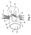
- FIG. 8 is a perspective view of a suture attachment device in accordance with yet a further embodiment.
- FIG. 9 is a flatten view of the external surface of the device of FIG. 8 .
- FIG. 10 is a perspective view of a vascular closure delivery device including a suture knot system in accordance with one embodiment.
- a suture attachment device for fastening multiple suture filaments at a wound or surgical site is provided.
- the suture attachment device or suture lock, may be used to fasten multiple suture filaments to seal a vascular access wound. It should be appreciated by those skilled in the art, however, the suture attachment device may be used in a variety of situations to seal any suitable wound, incision, puncture, or suture site.
- the suture attachment device 5 (or suture lock) includes an lock body 10 and, optionally, an outer sleeve 24 .
- the lock body 10 and the outer sleeve 24 may be manufactured as a molded or machined bioabsorbable material or an implant grade polymer.
- the lock body 10 and the outer sleeve 24 may be any suitable material manufactured in any suitable manner.
- the lock body 10 is manufactured of an elastic material such that the lock body 10 has a flexible or nonrigid characteristic.
- the lock body 10 and the outer sleeve 24 are flexible such that they conform around the sutures to wrap the sutures.
- the sleeve 24 is more flexible than the lock body 10 .
- the lock body 10 and the outer sleeve 24 have complementary shapes such that the lock body 10 receive the outer sleeve 24 therearound, as is described more fully below. It should be noted that it is not necessary that the lock body 10 and the outer sleeve 24 have identical shapes. In the embodiment shown, both the lock body 10 and the outer sleeve 24 are substantially cylindrical. Alternatively, either or both of the lock body 10 and the outer sleeve 24 may be rectangular, spherical, or otherwise shaped.
- the lock body 10 extends along a longitudinal axis (axis line B-B of FIG.
- the lock body 10 includes a proximal surface 18 (farthest away from the vascular puncture) and a distal surface 20 (closest to the vascular puncture).
- One or more proximal surface passageways 12 are provided on the proximal surface 18 .
- One or more distal surface passageways 22 are provided on the distal surface 20 .
- the lock body 10 includes four proximal surface passageways 12 and four distal surface passageways 22 .
- more or fewer proximal surface passageways 12 or distal surface passageways 22 may be provided.
- an equal number of proximal surface passageways 12 is provided as distal surface passageways 22 .
- the number of proximal surface passageways 12 and the number of distal surface passageways 22 may not be equal.
- proximal apertures 14 are provided on an external wall 26 of the lock body 10 .
- Each proximal surface passageway 12 extends from the proximal surface 18 to the proximal aperture 14 .
- one proximal aperture 14 is provided for each proximal surface passageway 12 .
- a plurality of proximal surface passageways 12 may extend to a single proximal aperture 14 .
- a plurality of proximal apertures 14 may lead to a single proximal surface passageway 12 .
- One or more distal apertures 16 are provided on an external wall 26 of the lock body 10 .
- Each distal surface passageway 22 extends from the distal surface 20 to the distal aperture 16 .
- one distal aperture 16 is provided for each distal surface passageway 22 .
- a plurality of distal surface passageways 22 may extend to a single distal aperture 16 .
- a plurality of distal apertures 16 may lead to a single distal surface passageway 22 .
- the diameter of each of the proximal surface passageways 12 , the distal surface passageways 22 , the proximal apertures 14 , and the distal apertures 16 is sufficient to accommodate a suture filament 8 .
- the diameter of the proximal surface passageways 12 , the distal surface passageways 22 , the proximal apertures 14 , and the distal apertures 16 may be slightly greater than or slightly less than the outside diameter of suture filament 8 .
- the diameter of the proximal surface passageways 12 , the distal surface passageways 22 , the proximal apertures 14 , and the distal apertures 16 may be between approximately 2% and approximately 50% larger or smaller than the outside diameter of the suture filament 8 , for example approximately 33% larger or smaller than the outside diameter of the suture filament 8 .
- the lock body 10 receives a plurality of suture filaments 8 to fasten the filaments 8 .
- the suture filaments are threaded through the proximal surface passageways 12 and the distal surface passageways 22 .
- the proximal and distal surface passageways 12 , 20 are shown in FIGS. 1 and 2 being spaced apart and isolated from each other.
- a pathway for a suture filament 8 from the proximal surface 18 to the distal surface 20 through a first set of proximal and distal surface passageways 12 , 22 is shown in FIGS. 1 and 2 as being separate and distinct from a pathway for another suture filament 8 extending through a second set of proximal and distal surface passageways 12 , 22 .
- the suture filaments may be threaded through the lock body 10 in any suitable manner.
- the threading is described with first threading through the proximal surface passageways 12 and then through the distal surface passageways 22 .
- a suture filament 8 is threaded into a proximal surface passageway 12 and out a proximal aperture 14 , extended over a portion of the external wall 26 , threaded into a distal aperture 16 and out a distal surface passageway 22 .
- the proximal surface passageway 12 and the distal surface passageway 22 together allow for the translational movement of the lock body 10 with respect to the suture filament 8 .
- One or more filaments 8 may be threaded through each set of proximal surface passageways 12 , proximal apertures 14 , distal apertures 16 , and distal surface passageways 22 .
- a single proximal aperture 14 or distal aperture 16 may be provided for a plurality of proximal passageways 12 or distal passageways 22 , respectively.
- a single passageway including a proximal portion and a distal portion may be provided extending between a proximal aperture 14 and a distal aperture 16 .
- the positioning of the suture filaments 8 within the body 10 once threaded can be varied to control resistance of the suture filaments 8 .
- the path of the suture filaments 8 through the body 10 may be longer or shorter, more or less tortuous, etc. Resistance of the suture filaments 8 to the lock body 10 contributes to the ease of deployment of the suture filaments 8 and the ability of the suture filaments 8 to stay in place once the lock body 10 is deployed.
- the proximal surface passageway 18 and distal surface passageway 22 are aligned with respect to the radial axis (A-A) of the lock body 10 .
- the proximal surface passageway 18 and the distal surface passageway 22 may be offset, for example by an acute angle with respect to the radial axis (A-A) of the lock body 10 . This embodiment allows for more surface area over which the sutures travel which, in turn, provides more drag force.
- an anchor 6 is deployed at a vascular puncture 2 of an artery 4 .
- the anchor 6 may comprise a suture or may comprise a separate device coupled to a suture.
- the anchor 6 comprises a metal anchor such as a needle coupled to a suture filament 8 .
- a plurality of anchors and associated suture filaments may be used to close a single vascular puncture.
- four anchors 6 and associated suture filaments 8 are used. Obviously, any suitable number of anchors and or filaments may be used.
- the suture filaments 8 extend from the anchor, through the distal surface passageway 22 , through the distal aperture 16 , over the external wall 26 , through the proximal aperture 14 , and out the proximal surface passageway 12 .
- the lock body 10 is positioned proximally of the anchor 6 .
- a pushing force is applied against the lock body 10 in the direction of the arrow (see FIG. 1 )
- the lock body 10 is driven along the suture filaments 8 , until the lock body 10 contacts with the vascular puncture 2 , or until force is no longer applied.
- a pusher may be used to apply the pushing force to the lock body 10 .
- a suture knot system 300 may be used to deploy the lock body 10 and to keep the sutures in tension, for example by pulling the sutures taut proximally.
- each suture filament 8 with proximal surface passageway 12 , distal surface passageway 22 , and external wall 26 is sufficient to retain the lock body 10 in contact with the vascular puncture 2 .
- an outer sleeve 24 may be deployed over the lock body 10 .
- FIG. 3 illustrates the outer sleeve 24 deployed over the lock body 10 .
- the suture sleeve 24 may be slidably placed over the lock body 10 .
- the suture sleeve 24 is frictionally engaged with the external wall 26 of the lock body 10 . This frictional engagement provides additional resistance to retain the lock body 10 in contact with the vascular puncture.
- the outer sleeve 24 may be sized and configured to snugly fit over the lock body 10 and suture filaments 8 extending over the external wall 26 of the lock body 10 . In various embodiments, an outer sleeve is not used.
- FIGS. 4 and 5 illustrate an alternate embodiment of a suture attachment device.
- the suture attachment device comprises a lock body 50 .
- the lock body 50 may comprise a molded piece of bioabsorbable material. As shown, the lock body 50 is substantially cylindrical. Alternatively, the lock body 50 may be rectangular, spherical, or otherwise shaped.
- the lock body extends along a longitudinal axis (axis line B) which is substantially perpendicular to a radial axis (axis line A).
- the lock body 50 has a proximal surface 58 (farthest away from the vascular puncture) and a distal surface 60 (closest to the vascular puncture).
- An internal cavity is provided within the lock body 50 , extending the lock body 50 substantially along the longitudinal axis (axis line B).
- the internal cavity 68 has an internal cavity wall 70 . Defined in the internal cavity wall 70 is at least one proximal passageway 52 and at least one distal passageway 62 . In the embodiment shown, four proximal passageways 52 and four distal passageways 62 are provided. More or fewer proximal passageways 52 and distal passageways 62 may be provided and the number of proximal passageways 52 and the number of distal passageways 62 need not be equal.
- the proximal passageway 52 terminates in a proximal aperture 54 defined in an external wall 66 of the lock body 50 .
- one proximal aperture 54 is provided for each proximal passageway 12 .
- a plurality of proximal passageways 52 may extend to a single proximal aperture 54 .
- a plurality of proximal apertures 54 may lead to a single proximal passageway 52 .
- the distal passageway 62 terminates in a distal aperture 56 defined in the external wall 66 of the lock body 50 .
- one distal aperture 56 is provided for each distal passageway 62 .
- a plurality of distal passageways 52 may extend to a single distal aperture 56 .
- a plurality of distal apertures 56 may lead to a single distal passageway 62 .
- the diameter of each of the proximal passageways 52 , the distal passageways 62 , the proximal apertures 54 , and the distal apertures 56 is sufficient to accommodate a suture filament 8 .
- the diameter of the proximal surface passageways 52 , the distal surface passageways 62 , the proximal apertures 54 , and the distal apertures 56 may be slightly greater than or slightly less than the outside diameter of suture filament 8 .
- the lock body 50 receives a plurality of suture filaments 8 to fasten the filaments 8 .
- the suture filaments are threaded through the proximal passageways 52 and the distal surface passageways 62 .
- the order of threading before use is not of importance. However, for the purposes of illustration, the threading is described with first threading through the proximal passageways 52 and then through the distal passageways 62 . Accordingly, a suture filament 8 is threaded into a proximal passageway 52 and out a proximal aperture 54 , extended over a portion of the external wall 66 , threaded into a distal aperture 56 and out a distal passageway 62 .
- the proximal passageway 52 and the distal passageway 62 together allow for the translational movement of the lock body 50 with respect to the suture filament 8 .
- One or more filaments 8 may be threaded through each set of proximal passageways 52 , proximal apertures 54 , distal apertures 56 , and distal passageways 62 .
- a single proximal aperture 54 or distal aperture 56 may be provided for a plurality of proximal passageways 52 or distal passageways 62 , respectively.
- a single proximal passageway 52 or distal passageway 62 may be provided for a plurality of proximal apertures 54 or distal apertures 56 , respectively.
- the positioning of the suture filaments 8 within the body 50 once threaded can be varied to control resistance of the suture filaments 8 .
- the path of the suture filaments 8 through the body 50 may be longer or shorter, more or less tortuous, etc. Resistance of the suture filaments 8 to the lock body 50 contributes to the ease of deployment of the suture filaments 8 and the ability of the suture filaments 8 to stay in place once the lock body 50 is deployed.
- the suture lock device of FIGS. 4 and 5 is deployed in the same manner as that of FIGS. 1 through 3 .
- An anchor is deployed at a vascular puncture of an artery.
- the anchor may comprise a suture or may comprise a separate device, such as a needle, coupled to a suture.
- Suture filaments 8 extend from the anchor, through the distal passageway 62 , through the distal aperture 56 , over the external wall 66 , through the proximal aperture 54 , and out the proximal passageway 52 .
- the lock body 50 is positioned proximally of the anchor. As a pushing force is applied against the lock body 50 towards the vascular puncture site, the lock body 50 is driven along the suture filaments 8 , until the lock body 50 contacts with the vascular puncture, or until force is no longer applied. This pushing force, in turn, forces the wound to come together and provides an approximate sealing of the vascular wound. Before, during, or after suture lock device deployment, the physician may apply manual compression to the surgical site to reduce bleeding. A pusher may be used to apply the pushing force to the lock body 50 .
- each suture filament 8 with proximal passageway 52 , distal passageway 62 , and external wall 66 is sufficient to retain the lock body 50 in contact with the vascular puncture.
- an outer sleeve similar to outer sleeve 24 of FIG. 3 , may be deployed over the lock body 50 .
- the proximal passageway 52 and distal passageway 62 are aligned with respect to the radial axis (A) of the lock body 50 .
- the proximal passageway 52 and the distal passageway 62 may be offset, for example by an acute angle with respect to the radial axis (A) of the lock body 50 . This embodiment allows for more surface area over which the sutures travel which, in turn, provides more drag force.
- FIGS. 6 and 7 illustrate a further embodiment of a suture lock device.
- the suture lock device comprises a lock body 90 .
- the lock body 90 may comprise a molded piece of bioabsorbable material or may alternatively comprise any suitable material manufactured in any suitable manner.
- the lock body 90 comprises a tapered cylinder.
- the cylinder tapers at its distal end (closest to the vascular puncture) to enable easy traveling into subcutaneous tissue.
- the lock body 90 may not be tapered.
- the lock body 90 may be provided in any suitable shape and may be round, flat, spherical, rectangular, or other.
- the lock body 90 extends along a longitudinal axis which is substantially perpendicular to a radial axis.
- the lock body 90 includes a proximal surface 98 (farthest away from the vascular puncture) and a distal surface 100 (closest to the vascular puncture). At least one proximal surface passageway 92 is provided on the proximal surface 98 while at least one distal surface aperture 102 is provided on the distal surface 100 . As shown, each proximal surface passageway 92 extends to a corresponding distal surface aperture 102 . In the embodiment illustrated in FIG. 6 , there are four proximal surface passageways 92 and four distal surface apertures 102 . In alternative embodiments, more or fewer proximal surface passageways 92 and more or fewer distal surface apertures 102 may be provided.
- FIG. 7 illustrates a schematic cross section of the suture lock device 90 . As shown, each proximal surface passageway 92 terminates in a distal surface aperture 102 .
- the diameter of each of the proximal surface passageways 92 and the distal surface apertures 102 is sufficient to accommodate a suture filament 8 .
- the diameter of the proximal surface passageways 92 and the distal surface apertures 102 may be slightly greater than the outside diameter of suture filament 8 .
- the diameter of the proximal surface passageway 92 increases as it passes through the suture lock device 90 , terminating in a maximum diameter at distal surface aperture 102 .
- An anchor is deployed at a vascular puncture of an artery.
- the anchor may comprise a suture, such as a suture knot, or may comprise a separate device, such as a needle, coupled to a suture.
- Suture filaments 8 extend from the anchor, through the distal surface aperture 102 and out the proximal surface passageway 92 .
- the lock body 90 is positioned proximally of the anchor.
- a pusher may be used to apply the pushing force to the lock body 90 .
- the proximal surface passageways 92 allow for the translational movement of the suture lock device 90 with respect to the suture filament 8 . Once the suture lock device 90 is in contact with a vascular puncture, the drag force created by contact of suture filament 8 with proximal passageway 92 is sufficient to retain the suture lock device 90 in contact with the vascular puncture.
- FIG. 8 illustrates the suture lock device as deployed.
- FIG. 9 illustrates a “rolled out” version of the suture lock device for purposes of illustration.
- the suture lock device 110 includes a base element 122 comprising one or more crimping means 114 . As shown, the crimping means 114 are integral to the base element 122 .
- the base element 122 is substantially tubular and cylindrical, having a distal side 106 and a proximal side 108 . When deployed, the proximal side is nearest to the vascular puncture while the distal side is farthest from the vascular puncture.
- the base element 122 may be any suitable shape, for example, the base element 122 may be rectangular or spherical.
- the base element 122 extends along a longitudinal axis substantially perpendicular to a radial axis.
- the base element 122 includes an internal cavity 125 that extends through the device along the longitudinal axis.
- a plurality of entrance apertures 112 and an exit aperture 120 are provided along the base element 122 .
- the entrance apertures 112 are positioned along the proximal side 108 of the suture lock device 110 and the exit aperture 120 is positioned along the distal side 106 of the suture lock device 110 when deployed.
- each crimping means comprises a suture clip 115 , and a crimping slot 118 defined between the suture clip 115 and the base element 122 .
- the suture clip 115 is a portion of the base element 122 cut along three walls 117 , 117 a and hinged along the fourth 119 .
- Two notches 123 are provided along one wall 117 a of the suture clip 115 to aid in preventing longitudinal migration of the sutures 8 .
- the notches 123 maintain the sutures in a central position of the suture clip, as described more fully below.
- the suture clip 115 may not be integral with the base element 122 .
- a portion of the base element 122 may be cut away and a separate suture clip 115 fixedly secured to the base element 122 .
- a suture aperture 116 is provided on each suture clip 115 .
- Two pairs of sutures are threaded through the suture lock device 110 .
- a first pair of sutures 8 is threaded into the central cavity 125 of the suture lock device 110 through a first entrance aperture 112 a .
- the sutures 8 are extended under a first portion of the first suture clip 115 a and threaded out through the suture aperture 116 of the suture clip.
- the sutures 8 are then threaded through the crimping slot 118 along wall 117 a between notches 123 , thereby reentering the central cavity 125 .
- the sutures 8 are then threaded within the central cavity 125 to exit through the exit aperture 120 .
- a second pair of sutures 8 is threaded into the central cavity 125 of the suture lock device 110 through a second entrance aperture 112 b .
- the sutures 8 are extended under a first portion of the second suture clip 115 b and threaded out through the suture aperture 116 of the suture clip.
- the sutures 8 are then threaded through the crimping slot 118 along wall 117 a between notches 123 , thereby reentering the central cavity 125 .
- the sutures 8 are then threaded within the central cavity to exit trough the exit aperture 120 .
- the entrance apertures 112 , suture apertures 116 , crimping slots 118 , and exit aperture 120 allow for the translational movement of the suture lock device 110 with respect to the suture filaments 8 .
- the frictional engagement of the sutures with the suture lock device 100 is sufficient to retain the suture lock device 100 in contact with the vascular puncture. While the embodiment of FIGS. 10 and 11 is described specifically with reference to two pairs of suture filaments, it is to be appreciated than any suitable number of suture filaments may be used and even numbers of suture filaments are not necessary.
- FIG. 10 illustrates a vascular closure delivery system including a suture knot system 300 .
- the suture knot system 300 may be used to deploy the suture lock device 10 (or 50 , 90 , or 110 ).
- the suture knot system 300 includes a suture portion 5 and a handle 310 .
- a tensioning knob 312 may be disposed at a proximal end of the handle 310 .
- the suture lock device 300 may be provided at the distal end of the suture portion 5 .
- Sutures extend from the surgical site, through the suture portion 5 and, optionally, through the handle 300 to the tensioning knob 312 .
- the sutures travel through the handle 310 and the handle 310 acts as a pusher to push the suture lock device 10 to the surgical site.
- the tensioning knob 312 may additionally be pulled or actuated to affirmatively tense the sutures.
- the vascular closure delivery system and suture knot system 300 are more fully described in copending U.S. patent application Ser. Nos. 11/551,523, filed Oct. 20, 2006; and 11/551,635, filed Oct. 20, 2006, both herein incorporated by reference.
Abstract
Description
Claims (11)
Priority Applications (3)
| Application Number | Priority Date | Filing Date | Title |
|---|---|---|---|
| US11/551,642 US8080035B2 (en) | 2006-10-20 | 2006-10-20 | Suture attachment device |
| EP07839711A EP2083705A2 (en) | 2006-10-20 | 2007-10-18 | Suture attachment device |
| PCT/US2007/022350 WO2008051481A2 (en) | 2006-10-20 | 2007-10-18 | Suture attachment device |
Applications Claiming Priority (1)
| Application Number | Priority Date | Filing Date | Title |
|---|---|---|---|
| US11/551,642 US8080035B2 (en) | 2006-10-20 | 2006-10-20 | Suture attachment device |
Publications (2)
| Publication Number | Publication Date |
|---|---|
| US20080097527A1 US20080097527A1 (en) | 2008-04-24 |
| US8080035B2 true US8080035B2 (en) | 2011-12-20 |
Family
ID=38996712
Family Applications (1)
| Application Number | Title | Priority Date | Filing Date |
|---|---|---|---|
| US11/551,642 Expired - Fee Related US8080035B2 (en) | 2006-10-20 | 2006-10-20 | Suture attachment device |
Country Status (3)
| Country | Link |
|---|---|
| US (1) | US8080035B2 (en) |
| EP (1) | EP2083705A2 (en) |
| WO (1) | WO2008051481A2 (en) |
Families Citing this family (8)
| Publication number | Priority date | Publication date | Assignee | Title |
|---|---|---|---|---|
| US8834493B2 (en) * | 2006-10-20 | 2014-09-16 | St. Jude Medical, Cardiology Division, Inc. | Device and method for vascular closure |
| US8906044B2 (en) * | 2006-10-20 | 2014-12-09 | St. Jude Medical, Cardiology Division, Inc. | Knot pusher device |
| US9107656B2 (en) * | 2006-10-20 | 2015-08-18 | St. Jude Medical, Cardiovascular Division, Inc. | Internal suturing device leg suspension system and method of use |
| US8834494B2 (en) * | 2006-10-20 | 2014-09-16 | St. Jude Medical, Cardiology Division, Inc. | Method and device for automated needle deployment |
| US9168034B2 (en) * | 2010-03-12 | 2015-10-27 | Linvatec Corporation | Suture anchor |
| US8663249B2 (en) | 2010-04-29 | 2014-03-04 | Vinay Badhwar | Automatic suturing apparatus and methods of use |
| US10893861B2 (en) * | 2016-06-17 | 2021-01-19 | Lsi Solutions, Inc. | Surgical port for stay sutures |
| JP6840839B2 (en) * | 2017-04-14 | 2021-03-10 | オリンパス株式会社 | Thread fixture |
Citations (34)
| Publication number | Priority date | Publication date | Assignee | Title |
|---|---|---|---|---|
| US5084058A (en) | 1990-04-25 | 1992-01-28 | Mitek Surgical Products, Inc. | Suture rundown tool and cutter system |
| US5324298A (en) | 1992-11-03 | 1994-06-28 | Edward H. Phillips | Endoscopic knot pushing instrument |
| US5364408A (en) | 1992-09-04 | 1994-11-15 | Laurus Medical Corporation | Endoscopic suture system |
| US5458609A (en) | 1992-09-04 | 1995-10-17 | Laurus Medical Corporation | Surgical needle and retainer system |
| US5496348A (en) * | 1993-05-14 | 1996-03-05 | Bonutti; Peter M. | Suture anchor |
| US5562684A (en) | 1994-10-11 | 1996-10-08 | Ethicon, Inc. | Surgical knot pusher device and improved method of forming knots |
| US5643292A (en) | 1995-01-10 | 1997-07-01 | Applied Medical Resources Corporation | Percutaneous suturing device |
| US5797928A (en) | 1995-01-20 | 1998-08-25 | Olympus Optical Co., Ltd. | Ligating apparatus |
| US5845645A (en) * | 1993-05-14 | 1998-12-08 | Bonutti; Peter M. | Method of anchoring a suture |
| US5868762A (en) | 1997-09-25 | 1999-02-09 | Sub-Q, Inc. | Percutaneous hemostatic suturing device and method |
| US5984933A (en) | 1994-12-29 | 1999-11-16 | Yoon; Inbae | Apparatus for suturing tissue |
| US5993459A (en) * | 1996-10-04 | 1999-11-30 | Larsen; Scott | Suture anchor installation system with insertion tool |
| US6059800A (en) | 1997-09-10 | 2000-05-09 | Applied Medical Resources Corporation | Suturing apparatus and method |
| US6074395A (en) | 1999-02-02 | 2000-06-13 | Linvatec Corporation | Cannulated tissue anchor insertion system |
| US6132439A (en) | 1999-02-17 | 2000-10-17 | X-Site, L.L.C. | Knot pusher |
| US6283947B1 (en) | 1999-07-13 | 2001-09-04 | Advanced Cardiovascular Systems, Inc. | Local drug delivery injection catheter |
| US6358259B1 (en) | 1992-09-04 | 2002-03-19 | University College London | Device for use in tying knots |
| US20030040712A1 (en) | 1999-07-13 | 2003-02-27 | Pinaki Ray | Substance delivery apparatus and a method of delivering a therapeutic substance to an anatomical passageway |
| US6533795B1 (en) | 2000-04-11 | 2003-03-18 | Opus Medical, Inc | Dual function suturing apparatus and method |
| US20030181926A1 (en) | 2001-12-07 | 2003-09-25 | Michael Dana | Suture trimmer |
| US6702825B2 (en) | 1999-09-20 | 2004-03-09 | Ev3 Sunnyvale, Inc. | Anastomosis catheter |
| US6716224B2 (en) | 2000-08-28 | 2004-04-06 | Linvatec Corporation | Intracorporeal knot tier |
| US20040068273A1 (en) | 2002-10-02 | 2004-04-08 | Ibionics Corporation | Automatic laparoscopic incision closing apparatus |
| US20040097973A1 (en) | 2000-03-20 | 2004-05-20 | Amir Loshakove | Transvascular bybass method and system |
| US6855124B1 (en) | 2002-10-02 | 2005-02-15 | Advanced Cardiovascular Systems, Inc. | Flexible polymer needle catheter |
| US20050159812A1 (en) * | 2004-01-16 | 2005-07-21 | Dinger Fred B.Iii | Bone-tendon-bone implant |
| US7160309B2 (en) | 2002-12-31 | 2007-01-09 | Laveille Kao Voss | Systems for anchoring a medical device in a body lumen |
| US7226467B2 (en) | 1999-04-09 | 2007-06-05 | Evalve, Inc. | Fixation device delivery catheter, systems and methods of use |
| US20070203507A1 (en) | 2005-08-26 | 2007-08-30 | G-Surge Medical Solutions, Inc. | Suturing apparatus and methods |
| US20080033459A1 (en) | 2006-08-03 | 2008-02-07 | Surgsolutions, Llp | Suturing apparatus for closing tissue defects |
| US20080097480A1 (en) | 2006-10-20 | 2008-04-24 | Gary James Schorr | Internal suturing device leg suspension system and method of use |
| US20080097484A1 (en) | 2006-10-20 | 2008-04-24 | Jyue Boon Lim | Knot pusher device |
| US20080097481A1 (en) | 2006-10-20 | 2008-04-24 | Gary James Schorr | Method and device for automated needle deployment |
| US20080097479A1 (en) | 2006-10-20 | 2008-04-24 | Raimar Boehlke | Device and method for vascular closure |
Family Cites Families (5)
| Publication number | Priority date | Publication date | Assignee | Title |
|---|---|---|---|---|
| US5391173A (en) * | 1994-02-10 | 1995-02-21 | Wilk; Peter J. | Laparoscopic suturing technique and associated device |
| US5702397A (en) * | 1996-02-20 | 1997-12-30 | Medicinelodge, Inc. | Ligament bone anchor and method for its use |
| US6066160A (en) * | 1998-11-23 | 2000-05-23 | Quickie Llc | Passive knotless suture terminator for use in minimally invasive surgery and to facilitate standard tissue securing |
| US7887551B2 (en) * | 1999-12-02 | 2011-02-15 | Smith & Nephew, Inc. | Soft tissue attachment and repair |
| EP2032044A2 (en) * | 2006-05-25 | 2009-03-11 | Mitralign, Inc. | Lockers for surgical tensioning members and methods of using the same to secure surgical tensioning members |
-
2006
- 2006-10-20 US US11/551,642 patent/US8080035B2/en not_active Expired - Fee Related
-
2007
- 2007-10-18 WO PCT/US2007/022350 patent/WO2008051481A2/en active Application Filing
- 2007-10-18 EP EP07839711A patent/EP2083705A2/en not_active Withdrawn
Patent Citations (34)
| Publication number | Priority date | Publication date | Assignee | Title |
|---|---|---|---|---|
| US5084058A (en) | 1990-04-25 | 1992-01-28 | Mitek Surgical Products, Inc. | Suture rundown tool and cutter system |
| US5364408A (en) | 1992-09-04 | 1994-11-15 | Laurus Medical Corporation | Endoscopic suture system |
| US5458609A (en) | 1992-09-04 | 1995-10-17 | Laurus Medical Corporation | Surgical needle and retainer system |
| US6358259B1 (en) | 1992-09-04 | 2002-03-19 | University College London | Device for use in tying knots |
| US5324298A (en) | 1992-11-03 | 1994-06-28 | Edward H. Phillips | Endoscopic knot pushing instrument |
| US5845645A (en) * | 1993-05-14 | 1998-12-08 | Bonutti; Peter M. | Method of anchoring a suture |
| US5496348A (en) * | 1993-05-14 | 1996-03-05 | Bonutti; Peter M. | Suture anchor |
| US5562684A (en) | 1994-10-11 | 1996-10-08 | Ethicon, Inc. | Surgical knot pusher device and improved method of forming knots |
| US5984933A (en) | 1994-12-29 | 1999-11-16 | Yoon; Inbae | Apparatus for suturing tissue |
| US5643292A (en) | 1995-01-10 | 1997-07-01 | Applied Medical Resources Corporation | Percutaneous suturing device |
| US5797928A (en) | 1995-01-20 | 1998-08-25 | Olympus Optical Co., Ltd. | Ligating apparatus |
| US5993459A (en) * | 1996-10-04 | 1999-11-30 | Larsen; Scott | Suture anchor installation system with insertion tool |
| US6059800A (en) | 1997-09-10 | 2000-05-09 | Applied Medical Resources Corporation | Suturing apparatus and method |
| US5868762A (en) | 1997-09-25 | 1999-02-09 | Sub-Q, Inc. | Percutaneous hemostatic suturing device and method |
| US6074395A (en) | 1999-02-02 | 2000-06-13 | Linvatec Corporation | Cannulated tissue anchor insertion system |
| US6132439A (en) | 1999-02-17 | 2000-10-17 | X-Site, L.L.C. | Knot pusher |
| US7226467B2 (en) | 1999-04-09 | 2007-06-05 | Evalve, Inc. | Fixation device delivery catheter, systems and methods of use |
| US6283947B1 (en) | 1999-07-13 | 2001-09-04 | Advanced Cardiovascular Systems, Inc. | Local drug delivery injection catheter |
| US20030040712A1 (en) | 1999-07-13 | 2003-02-27 | Pinaki Ray | Substance delivery apparatus and a method of delivering a therapeutic substance to an anatomical passageway |
| US6702825B2 (en) | 1999-09-20 | 2004-03-09 | Ev3 Sunnyvale, Inc. | Anastomosis catheter |
| US20040097973A1 (en) | 2000-03-20 | 2004-05-20 | Amir Loshakove | Transvascular bybass method and system |
| US6533795B1 (en) | 2000-04-11 | 2003-03-18 | Opus Medical, Inc | Dual function suturing apparatus and method |
| US6716224B2 (en) | 2000-08-28 | 2004-04-06 | Linvatec Corporation | Intracorporeal knot tier |
| US20030181926A1 (en) | 2001-12-07 | 2003-09-25 | Michael Dana | Suture trimmer |
| US20040068273A1 (en) | 2002-10-02 | 2004-04-08 | Ibionics Corporation | Automatic laparoscopic incision closing apparatus |
| US6855124B1 (en) | 2002-10-02 | 2005-02-15 | Advanced Cardiovascular Systems, Inc. | Flexible polymer needle catheter |
| US7160309B2 (en) | 2002-12-31 | 2007-01-09 | Laveille Kao Voss | Systems for anchoring a medical device in a body lumen |
| US20050159812A1 (en) * | 2004-01-16 | 2005-07-21 | Dinger Fred B.Iii | Bone-tendon-bone implant |
| US20070203507A1 (en) | 2005-08-26 | 2007-08-30 | G-Surge Medical Solutions, Inc. | Suturing apparatus and methods |
| US20080033459A1 (en) | 2006-08-03 | 2008-02-07 | Surgsolutions, Llp | Suturing apparatus for closing tissue defects |
| US20080097480A1 (en) | 2006-10-20 | 2008-04-24 | Gary James Schorr | Internal suturing device leg suspension system and method of use |
| US20080097484A1 (en) | 2006-10-20 | 2008-04-24 | Jyue Boon Lim | Knot pusher device |
| US20080097481A1 (en) | 2006-10-20 | 2008-04-24 | Gary James Schorr | Method and device for automated needle deployment |
| US20080097479A1 (en) | 2006-10-20 | 2008-04-24 | Raimar Boehlke | Device and method for vascular closure |
Also Published As
| Publication number | Publication date |
|---|---|
| WO2008051481A2 (en) | 2008-05-02 |
| EP2083705A2 (en) | 2009-08-05 |
| US20080097527A1 (en) | 2008-04-24 |
| WO2008051481A3 (en) | 2008-07-17 |
Similar Documents
| Publication | Publication Date | Title |
|---|---|---|
| US8080035B2 (en) | Suture attachment device | |
| US11684356B2 (en) | Point-loading knotless fixation devices | |
| US9492160B2 (en) | Closure device and method for tissue repair | |
| US5814051A (en) | Suture anchor insertion system | |
| US7815652B2 (en) | Surgical fastener and instrument | |
| EP1331886B1 (en) | Closure device for tissue repair | |
| US5662681A (en) | Self locking closure for sealing percutaneous punctures | |
| US8696704B2 (en) | Methods and devices for repairing tissue | |
| EP2214564B1 (en) | Implantable purse string suture tensioning device | |
| AU2007200095B2 (en) | Closure device and method for tissue repair | |
| US20150351741A1 (en) | Anti-Backup Suture Anchor | |
| EP0591991A2 (en) | Suture loop locking device | |
| JP2001508316A (en) | Anatomical suture knot element and method therefor | |
| EP2900148B1 (en) | Device for approximating tissue | |
| WO2009042468A2 (en) | Meniscal repair system | |
| WO2013173366A1 (en) | Soft tissue suture anchor | |
| US20210052270A1 (en) | Self locking suture and self locking suture mediated closure device | |
| EP3884877A1 (en) | Double row collapsible suture construct |
Legal Events
| Date | Code | Title | Description |
|---|---|---|---|
| AS | Assignment |
Owner name: ST. JUDE MEDICAL, CARDIOLOGY DIVISION, INC., MINNE Free format text: ASSIGNMENT OF ASSIGNORS INTEREST;ASSIGNORS:LIM, JYUE BOON;SCHORR, GARY J.;REEL/FRAME:019012/0050 Effective date: 20070130 |
|
| ZAAA | Notice of allowance and fees due |
Free format text: ORIGINAL CODE: NOA |
|
| ZAAB | Notice of allowance mailed |
Free format text: ORIGINAL CODE: MN/=. |
|
| ZAAA | Notice of allowance and fees due |
Free format text: ORIGINAL CODE: NOA |
|
| STCF | Information on status: patent grant |
Free format text: PATENTED CASE |
|
| FPAY | Fee payment |
Year of fee payment: 4 |
|
| MAFP | Maintenance fee payment |
Free format text: PAYMENT OF MAINTENANCE FEE, 8TH YEAR, LARGE ENTITY (ORIGINAL EVENT CODE: M1552); ENTITY STATUS OF PATENT OWNER: LARGE ENTITY Year of fee payment: 8 |
|
| FEPP | Fee payment procedure |
Free format text: MAINTENANCE FEE REMINDER MAILED (ORIGINAL EVENT CODE: REM.); ENTITY STATUS OF PATENT OWNER: LARGE ENTITY |
|
| LAPS | Lapse for failure to pay maintenance fees |
Free format text: PATENT EXPIRED FOR FAILURE TO PAY MAINTENANCE FEES (ORIGINAL EVENT CODE: EXP.); ENTITY STATUS OF PATENT OWNER: LARGE ENTITY |
|
| STCH | Information on status: patent discontinuation |
Free format text: PATENT EXPIRED DUE TO NONPAYMENT OF MAINTENANCE FEES UNDER 37 CFR 1.362 |
|
| FP | Lapsed due to failure to pay maintenance fee |
Effective date: 20231220 |