US8083716B2 - Systems and methods allowing for reservoir air bubble management - Google Patents
Systems and methods allowing for reservoir air bubble management Download PDFInfo
- Publication number
- US8083716B2 US8083716B2 US11/964,649 US96464907A US8083716B2 US 8083716 B2 US8083716 B2 US 8083716B2 US 96464907 A US96464907 A US 96464907A US 8083716 B2 US8083716 B2 US 8083716B2
- Authority
- US
- United States
- Prior art keywords
- reservoir
- plunger head
- head body
- interior volume
- fluidic media
- Prior art date
- Legal status (The legal status is an assumption and is not a legal conclusion. Google has not performed a legal analysis and makes no representation as to the accuracy of the status listed.)
- Expired - Fee Related, expires
Links
- 238000000034 method Methods 0.000 title claims description 28
- 239000000463 material Substances 0.000 claims description 40
- 238000004891 communication Methods 0.000 claims description 30
- 239000012530 fluid Substances 0.000 claims description 30
- 230000013011 mating Effects 0.000 claims description 14
- 238000004519 manufacturing process Methods 0.000 claims 1
- 230000000670 limiting effect Effects 0.000 abstract description 4
- 238000001802 infusion Methods 0.000 description 26
- NOESYZHRGYRDHS-UHFFFAOYSA-N insulin Chemical compound N1C(=O)C(NC(=O)C(CCC(N)=O)NC(=O)C(CCC(O)=O)NC(=O)C(C(C)C)NC(=O)C(NC(=O)CN)C(C)CC)CSSCC(C(NC(CO)C(=O)NC(CC(C)C)C(=O)NC(CC=2C=CC(O)=CC=2)C(=O)NC(CCC(N)=O)C(=O)NC(CC(C)C)C(=O)NC(CCC(O)=O)C(=O)NC(CC(N)=O)C(=O)NC(CC=2C=CC(O)=CC=2)C(=O)NC(CSSCC(NC(=O)C(C(C)C)NC(=O)C(CC(C)C)NC(=O)C(CC=2C=CC(O)=CC=2)NC(=O)C(CC(C)C)NC(=O)C(C)NC(=O)C(CCC(O)=O)NC(=O)C(C(C)C)NC(=O)C(CC(C)C)NC(=O)C(CC=2NC=NC=2)NC(=O)C(CO)NC(=O)CNC2=O)C(=O)NCC(=O)NC(CCC(O)=O)C(=O)NC(CCCNC(N)=N)C(=O)NCC(=O)NC(CC=3C=CC=CC=3)C(=O)NC(CC=3C=CC=CC=3)C(=O)NC(CC=3C=CC(O)=CC=3)C(=O)NC(C(C)O)C(=O)N3C(CCC3)C(=O)NC(CCCCN)C(=O)NC(C)C(O)=O)C(=O)NC(CC(N)=O)C(O)=O)=O)NC(=O)C(C(C)CC)NC(=O)C(CO)NC(=O)C(C(C)O)NC(=O)C1CSSCC2NC(=O)C(CC(C)C)NC(=O)C(NC(=O)C(CCC(N)=O)NC(=O)C(CC(N)=O)NC(=O)C(NC(=O)C(N)CC=1C=CC=CC=1)C(C)C)CC1=CN=CN1 NOESYZHRGYRDHS-UHFFFAOYSA-N 0.000 description 20
- 102000004877 Insulin Human genes 0.000 description 10
- 108090001061 Insulin Proteins 0.000 description 10
- 229940125396 insulin Drugs 0.000 description 10
- 239000004033 plastic Substances 0.000 description 10
- 229920003023 plastic Polymers 0.000 description 10
- 239000000853 adhesive Substances 0.000 description 8
- 230000001070 adhesive effect Effects 0.000 description 8
- 239000002131 composite material Substances 0.000 description 7
- 239000003814 drug Substances 0.000 description 6
- 229920001971 elastomer Polymers 0.000 description 6
- 239000010410 layer Substances 0.000 description 6
- 239000005060 rubber Substances 0.000 description 6
- WQZGKKKJIJFFOK-GASJEMHNSA-N Glucose Natural products OC[C@H]1OC(O)[C@H](O)[C@@H](O)[C@@H]1O WQZGKKKJIJFFOK-GASJEMHNSA-N 0.000 description 5
- -1 but not limited to Substances 0.000 description 5
- 229940079593 drug Drugs 0.000 description 5
- 239000008103 glucose Substances 0.000 description 5
- 239000002184 metal Substances 0.000 description 5
- 239000008280 blood Substances 0.000 description 4
- 210000004369 blood Anatomy 0.000 description 4
- 239000000919 ceramic Substances 0.000 description 4
- 230000003247 decreasing effect Effects 0.000 description 4
- 206010012601 diabetes mellitus Diseases 0.000 description 4
- 239000011521 glass Substances 0.000 description 4
- 230000002209 hydrophobic effect Effects 0.000 description 4
- 229920001296 polysiloxane Polymers 0.000 description 3
- 238000011282 treatment Methods 0.000 description 3
- 208000017667 Chronic Disease Diseases 0.000 description 2
- 102000004190 Enzymes Human genes 0.000 description 2
- 108090000790 Enzymes Proteins 0.000 description 2
- 230000009286 beneficial effect Effects 0.000 description 2
- 230000008878 coupling Effects 0.000 description 2
- 238000010168 coupling process Methods 0.000 description 2
- 238000005859 coupling reaction Methods 0.000 description 2
- 238000003780 insertion Methods 0.000 description 2
- 230000037431 insertion Effects 0.000 description 2
- 238000007726 management method Methods 0.000 description 2
- 238000012986 modification Methods 0.000 description 2
- 230000004048 modification Effects 0.000 description 2
- 238000012545 processing Methods 0.000 description 2
- 230000002441 reversible effect Effects 0.000 description 2
- HIPFUWHNBHKOQN-UHFFFAOYSA-N CC(C)CN1CC1 Chemical compound CC(C)CN1CC1 HIPFUWHNBHKOQN-UHFFFAOYSA-N 0.000 description 1
- 208000019693 Lung disease Diseases 0.000 description 1
- 206010028980 Neoplasm Diseases 0.000 description 1
- FAPWRFPIFSIZLT-UHFFFAOYSA-M Sodium chloride Chemical compound [Na+].[Cl-] FAPWRFPIFSIZLT-UHFFFAOYSA-M 0.000 description 1
- 230000009471 action Effects 0.000 description 1
- 239000012790 adhesive layer Substances 0.000 description 1
- 230000008901 benefit Effects 0.000 description 1
- 201000011510 cancer Diseases 0.000 description 1
- 235000015872 dietary supplement Nutrition 0.000 description 1
- 201000010099 disease Diseases 0.000 description 1
- 208000037265 diseases, disorders, signs and symptoms Diseases 0.000 description 1
- 230000009977 dual effect Effects 0.000 description 1
- 238000005516 engineering process Methods 0.000 description 1
- 230000007613 environmental effect Effects 0.000 description 1
- 230000036571 hydration Effects 0.000 description 1
- 238000006703 hydration reaction Methods 0.000 description 1
- 239000007943 implant Substances 0.000 description 1
- 238000001746 injection moulding Methods 0.000 description 1
- 239000007788 liquid Substances 0.000 description 1
- 238000003754 machining Methods 0.000 description 1
- 238000000465 moulding Methods 0.000 description 1
- 230000003287 optical effect Effects 0.000 description 1
- 230000002093 peripheral effect Effects 0.000 description 1
- 229920002635 polyurethane Polymers 0.000 description 1
- 239000004814 polyurethane Substances 0.000 description 1
- 238000003825 pressing Methods 0.000 description 1
- 230000008569 process Effects 0.000 description 1
- 230000002829 reductive effect Effects 0.000 description 1
- 230000000717 retained effect Effects 0.000 description 1
- 238000007789 sealing Methods 0.000 description 1
- 229920002379 silicone rubber Polymers 0.000 description 1
- 239000004945 silicone rubber Substances 0.000 description 1
- 239000011780 sodium chloride Substances 0.000 description 1
- 239000000126 substance Substances 0.000 description 1
- 229920003051 synthetic elastomer Polymers 0.000 description 1
- 239000005061 synthetic rubber Substances 0.000 description 1
- 238000012546 transfer Methods 0.000 description 1
- XLYOFNOQVPJJNP-UHFFFAOYSA-N water Substances O XLYOFNOQVPJJNP-UHFFFAOYSA-N 0.000 description 1
Images
Classifications
-
- A—HUMAN NECESSITIES
- A61—MEDICAL OR VETERINARY SCIENCE; HYGIENE
- A61M—DEVICES FOR INTRODUCING MEDIA INTO, OR ONTO, THE BODY; DEVICES FOR TRANSDUCING BODY MEDIA OR FOR TAKING MEDIA FROM THE BODY; DEVICES FOR PRODUCING OR ENDING SLEEP OR STUPOR
- A61M5/00—Devices for bringing media into the body in a subcutaneous, intra-vascular or intramuscular way; Accessories therefor, e.g. filling or cleaning devices, arm-rests
- A61M5/14—Infusion devices, e.g. infusing by gravity; Blood infusion; Accessories therefor
- A61M5/142—Pressure infusion, e.g. using pumps
- A61M5/14244—Pressure infusion, e.g. using pumps adapted to be carried by the patient, e.g. portable on the body
- A61M5/14248—Pressure infusion, e.g. using pumps adapted to be carried by the patient, e.g. portable on the body of the skin patch type
-
- A—HUMAN NECESSITIES
- A61—MEDICAL OR VETERINARY SCIENCE; HYGIENE
- A61M—DEVICES FOR INTRODUCING MEDIA INTO, OR ONTO, THE BODY; DEVICES FOR TRANSDUCING BODY MEDIA OR FOR TAKING MEDIA FROM THE BODY; DEVICES FOR PRODUCING OR ENDING SLEEP OR STUPOR
- A61M5/00—Devices for bringing media into the body in a subcutaneous, intra-vascular or intramuscular way; Accessories therefor, e.g. filling or cleaning devices, arm-rests
- A61M5/14—Infusion devices, e.g. infusing by gravity; Blood infusion; Accessories therefor
- A61M5/1413—Modular systems comprising interconnecting elements
-
- A—HUMAN NECESSITIES
- A61—MEDICAL OR VETERINARY SCIENCE; HYGIENE
- A61M—DEVICES FOR INTRODUCING MEDIA INTO, OR ONTO, THE BODY; DEVICES FOR TRANSDUCING BODY MEDIA OR FOR TAKING MEDIA FROM THE BODY; DEVICES FOR PRODUCING OR ENDING SLEEP OR STUPOR
- A61M5/00—Devices for bringing media into the body in a subcutaneous, intra-vascular or intramuscular way; Accessories therefor, e.g. filling or cleaning devices, arm-rests
- A61M5/14—Infusion devices, e.g. infusing by gravity; Blood infusion; Accessories therefor
- A61M5/165—Filtering accessories, e.g. blood filters, filters for infusion liquids
-
- A—HUMAN NECESSITIES
- A61—MEDICAL OR VETERINARY SCIENCE; HYGIENE
- A61M—DEVICES FOR INTRODUCING MEDIA INTO, OR ONTO, THE BODY; DEVICES FOR TRANSDUCING BODY MEDIA OR FOR TAKING MEDIA FROM THE BODY; DEVICES FOR PRODUCING OR ENDING SLEEP OR STUPOR
- A61M5/00—Devices for bringing media into the body in a subcutaneous, intra-vascular or intramuscular way; Accessories therefor, e.g. filling or cleaning devices, arm-rests
- A61M5/36—Devices for bringing media into the body in a subcutaneous, intra-vascular or intramuscular way; Accessories therefor, e.g. filling or cleaning devices, arm-rests with means for eliminating or preventing injection or infusion of air into body
-
- A—HUMAN NECESSITIES
- A61—MEDICAL OR VETERINARY SCIENCE; HYGIENE
- A61M—DEVICES FOR INTRODUCING MEDIA INTO, OR ONTO, THE BODY; DEVICES FOR TRANSDUCING BODY MEDIA OR FOR TAKING MEDIA FROM THE BODY; DEVICES FOR PRODUCING OR ENDING SLEEP OR STUPOR
- A61M5/00—Devices for bringing media into the body in a subcutaneous, intra-vascular or intramuscular way; Accessories therefor, e.g. filling or cleaning devices, arm-rests
- A61M5/14—Infusion devices, e.g. infusing by gravity; Blood infusion; Accessories therefor
- A61M5/142—Pressure infusion, e.g. using pumps
- A61M5/14244—Pressure infusion, e.g. using pumps adapted to be carried by the patient, e.g. portable on the body
- A61M2005/14268—Pressure infusion, e.g. using pumps adapted to be carried by the patient, e.g. portable on the body with a reusable and a disposable component
-
- A—HUMAN NECESSITIES
- A61—MEDICAL OR VETERINARY SCIENCE; HYGIENE
- A61M—DEVICES FOR INTRODUCING MEDIA INTO, OR ONTO, THE BODY; DEVICES FOR TRANSDUCING BODY MEDIA OR FOR TAKING MEDIA FROM THE BODY; DEVICES FOR PRODUCING OR ENDING SLEEP OR STUPOR
- A61M5/00—Devices for bringing media into the body in a subcutaneous, intra-vascular or intramuscular way; Accessories therefor, e.g. filling or cleaning devices, arm-rests
- A61M5/178—Syringes
- A61M5/31—Details
- A61M5/315—Pistons; Piston-rods; Guiding, blocking or restricting the movement of the rod or piston; Appliances on the rod for facilitating dosing ; Dosing mechanisms
- A61M5/31511—Piston or piston-rod constructions, e.g. connection of piston with piston-rod
- A61M2005/31516—Piston or piston-rod constructions, e.g. connection of piston with piston-rod reducing dead-space in the syringe barrel after delivery
-
- A—HUMAN NECESSITIES
- A61—MEDICAL OR VETERINARY SCIENCE; HYGIENE
- A61M—DEVICES FOR INTRODUCING MEDIA INTO, OR ONTO, THE BODY; DEVICES FOR TRANSDUCING BODY MEDIA OR FOR TAKING MEDIA FROM THE BODY; DEVICES FOR PRODUCING OR ENDING SLEEP OR STUPOR
- A61M5/00—Devices for bringing media into the body in a subcutaneous, intra-vascular or intramuscular way; Accessories therefor, e.g. filling or cleaning devices, arm-rests
- A61M5/178—Syringes
- A61M5/31—Details
- A61M5/32—Needles; Details of needles pertaining to their connection with syringe or hub; Accessories for bringing the needle into, or holding the needle on, the body; Devices for protection of needles
- A61M5/34—Constructions for connecting the needle, e.g. to syringe nozzle or needle hub
- A61M2005/341—Constructions for connecting the needle, e.g. to syringe nozzle or needle hub angularly adjustable or angled away from the axis of the injector
-
- A—HUMAN NECESSITIES
- A61—MEDICAL OR VETERINARY SCIENCE; HYGIENE
- A61M—DEVICES FOR INTRODUCING MEDIA INTO, OR ONTO, THE BODY; DEVICES FOR TRANSDUCING BODY MEDIA OR FOR TAKING MEDIA FROM THE BODY; DEVICES FOR PRODUCING OR ENDING SLEEP OR STUPOR
- A61M2209/00—Ancillary equipment
- A61M2209/04—Tools for specific apparatus
- A61M2209/045—Tools for specific apparatus for filling, e.g. for filling reservoirs
Definitions
- Embodiments of the present invention relate to U.S. Provisional Application Ser. No. 60/927,032, filed Apr. 30, 2007, entitled “Needle Inserting, Reservoir Filling, Bubble Management, Fluid Flow Connections and Infusion Medium Delivery Systems and Methods with Same”, the contents of which are incorporated by reference herein and which is a basis for a claim of priority.
- Embodiments of the present invention relate to PCT International Application No. PCT/US2007/076641, filed Aug. 23, 2007, the contents of which are incorporated by reference herein, and which claims the benefit of U.S. Provisional Application Ser. No. 60/927,032, filed Apr. 30, 2007.
- Embodiments of the present invention relate generally to systems and methods with reservoirs and, in specific embodiments, to a system with a reservoir and a plunger that are shaped to limit a presence of air bubbles in a fluidic medium expelled from the reservoir.
- certain chronic diseases may be treated by delivering a medication or other substance to the body of a patient.
- diabetes is a chronic disease that is commonly treated by delivering defined amounts of insulin to a patient at appropriate times.
- manually operated syringes and insulin pens have been employed for delivering insulin to a patient.
- modern systems have been designed to include programmable pumps for delivering controlled amounts of medication to a patient.
- External pump type delivery devices include devices designed for use in a stationary location, such as a hospital, a clinic, or the like, and further include devices configured for ambulatory or portable use, such as devices that are designed to be carried by a patient, or the like.
- External pump type delivery devices may be connected in fluid flow communication to a patient or user, for example, through a suitable hollow tubing.
- the hollow tubing may be connected to a hollow needle that is designed to pierce the skin of the patient and to deliver a fluidic medium there-through. Alternatively, the hollow tubing may be connected directly to the patient as through a cannula, or the like.
- pump type delivery devices can be significantly more convenient to a patient, in that doses of insulin may be calculated and delivered automatically to a patient at any time during the day or night.
- insulin pumps may be automatically controlled to provide appropriate doses of a fluidic medium at appropriate times of need, based on sensed or monitored levels of blood glucose.
- pump type delivery devices have become an important aspect of modern medical treatments of various types of medical conditions, such as diabetes, and the like. As pump technologies improve and doctors and patients become more familiar with such devices, external medical infusion pump treatments are expected to increase in popularity and are expected to increase substantially in number over the next decade.
- a plunger head within a reservoir is shaped so as to limit a presence of air bubbles in a fluidic medium expelled from the reservoir.
- a reservoir is shaped so as to limit a presence of air bubbles in a fluidic medium expelled from the reservoir.
- both a reservoir and a plunger head within the reservoir are shaped so as to limit a presence of air bubbles in a fluidic medium expelled from the reservoir.
- a plunger head in accordance with an embodiment of the present invention is moveable within a reservoir.
- the plunger head is shaped to form a bubble trap region for trapping air bubbles that are in a fluidic medium as the fluidic medium is expelled from the reservoir by the plunger head.
- the plunger head has a concave portion that defines the bubble trap region.
- the plunger head includes a body portion, a first protrusion portion protruding from the body portion, and a second protrusion portion protruding from the body portion, where the bubble trap region is located between the first protrusion portion and the second protrusion portion.
- the first protrusion portion surrounds at least a portion of the second protrusion portion.
- the first protrusion portion extends a first distance from the body portion
- the second protrusion portion extends a second distance from the body portion, and the first distance is greater than the second distance.
- the second distance is greater than one-fourth of the first distance.
- the second protrusion portion includes a cavity for receiving a portion of a needle.
- the plunger head includes a curved surface that defines the bubble trap region, where the curved surface has a first end position, a second end position, and an innermost position.
- a depth of the bubble trap region is at least greater than one-half of a width of the bubble trap region from the first end position to the second end position.
- a system for delivering a fluidic medium in accordance with an embodiment of the present invention includes a reservoir and a plunger head.
- the reservoir includes a reservoir body portion having an interior volume for containing the fluidic medium, and a port in fluid flow communication with the interior volume.
- the plunger head is moveable within the reservoir, and the plunger head is shaped to form a bubble trap region for trapping air bubbles that are in the fluidic medium as the fluidic medium is being expelled from the interior volume through the port by the plunger head.
- the plunger head has a concave portion that defines the bubble trap region.
- the plunger head includes a body portion, a first protrusion portion protruding from the body portion, and a second protrusion portion protruding from the body portion, where the bubble trap region is located between the first protrusion portion and the second protrusion portion.
- the first protrusion portion surrounds at least a portion of the second protrusion portion.
- the first protrusion portion extends a first distance from the body portion
- the second protrusion portion extends a second distance from the body portion
- the first distance is greater than the second distance.
- the second distance is greater than one-fourth of the first distance.
- the second protrusion portion is aligned with the port such that when a needle is inserted into the port, an end of the needle is directed toward the second protrusion portion. Also, in various embodiments, the second protrusion portion includes a cavity for receiving a portion of a needle.
- the reservoir further includes a reservoir bubble trap portion having a volume in fluid flow communication with the interior volume for trapping air bubbles that are in the fluidic medium as the fluidic medium is being expelled from the interior volume.
- a contour of the first protrusion portion of the plunger head substantially matches an inner contour of the reservoir bubble trap portion.
- the first protrusion portion of the plunger head is shaped and positioned such that the first protrusion portion extends at least partially into the volume of the reservoir bubble trap portion when the plunger head is sufficiently advanced within the reservoir.
- the first protrusion portion of the plunger head is shaped and positioned such that when the plunger head is fully advanced within the reservoir the first protrusion portion substantially fills the volume of the reservoir bubble trap portion.
- the reservoir is shaped such that in order for the fluidic medium to flow from the volume of the reservoir bubble trap portion to the port, the fluidic medium must flow through the interior volume.
- the reservoir includes a material for shunting air bubbles in the fluidic medium away from the port and toward the volume of the reservoir bubble trap portion when the fluidic medium is being expelled from the interior volume.
- the reservoir further includes a channel that leads from the interior volume to the port.
- the reservoir bubble trap portion includes a first portion that extends from the reservoir body portion away from the interior volume, and a second portion that returns back toward the interior volume, where the reservoir bubble trap portion encircles at least a portion of the channel.
- the system further includes a drive device, a plunger arm, a disposable housing, and a durable housing.
- the drive device includes a linkage portion and a motor for moving the linkage portion.
- the plunger arm is connected to the plunger head, and the plunger arm has a mating portion for mating with the linkage portion of the drive device.
- the disposable housing allows for housing the reservoir and for being secured to a user.
- the durable housing allows for housing the motor of the drive device, where the durable housing is configured to be selectively engaged with and disengaged from the disposable housing.
- a method in accordance with an embodiment of the present invention allows for expelling a fluidic medium from a reservoir using a plunger head.
- the plunger head has a concave portion that defines a bubble trap region.
- the method includes expelling the fluidic medium from the reservoir using the plunger head, and trapping, in the bubble trap region defined by the concave portion of the plunger head, air bubbles that are in the fluidic medium as the fluidic medium is being expelled from the reservoir by the plunger head.
- a system in accordance with an embodiment of the present invention includes a reservoir and a plunger head.
- the plunger head is moveable within the reservoir and has a cavity for receiving at least a portion of a needle when the plunger head is sufficiently advanced within the reservoir and the portion of the needle is inserted into the reservoir.
- the reservoir has a reservoir body portion and a neck portion.
- the plunger head has a plunger body portion and a plunger neck portion and the cavity is in the plunger neck portion.
- the system further includes a seal surrounding at least a part of the plunger body portion, where the seal is in contact with the reservoir body portion of the reservoir when the plunger body portion is within the reservoir body portion of the reservoir.
- the system further includes a septum positioned at an end of the neck portion of the reservoir, and the cavity of the plunger neck portion is located in a position such that the cavity receives the portion of the needle when the plunger head is sufficiently advanced within the reservoir and the needle pierces the septum.
- an opening of the cavity of the plunger neck portion is located approximately at a center of an end surface of the plunger head.
- a contour of an outer surface of the plunger neck portion substantially matches a contour of an inner surface of the neck portion of the reservoir.
- a diameter of an outer surface of the plunger neck portion substantially matches a diameter of an inner surface of the neck portion of the reservoir.
- the reservoir further includes a sloped portion between the reservoir body portion and the neck portion
- the plunger head further includes a plunger sloped portion between the plunger body portion and the plunger neck portion.
- the system further includes a septum positioned at an end of the neck portion of the reservoir, and a length of the plunger neck portion from an end of the plunger neck portion to the plunger sloped portion substantially matches a length of the neck portion of the reservoir from the septum to the sloped portion of the reservoir.
- the cavity of the plunger neck portion extends into the plunger neck portion a distance that is greater than one-fourth of the length of the plunger neck portion.
- the plunger neck portion is shaped such that the plunger neck portion substantially fills an area within the neck portion of the reservoir when the plunger head is fully advanced within the reservoir.
- the system further includes a drive device including a linkage portion and a motor for moving the linkage portion, and a plunger arm connected to the plunger head, where the plunger arm has a mating portion for mating with the linkage portion of the drive device.
- the system further includes a disposable housing for housing the reservoir and for being secured to a user, and a durable housing for housing the motor of the drive device, where the durable housing is configured to be selectively engaged with and disengaged from the disposable housing.
- a method in accordance with an embodiment of the present invention includes piercing a septum of a reservoir with a needle, and moving a plunger head within the reservoir such that at least a portion of the needle is received within a cavity of the plunger head.
- the moving includes moving the plunger head within the reservoir such that a plunger neck portion of the plunger head extends into a neck portion of the reservoir.
- the moving includes moving the plunger head within the reservoir such that a portion of the plunger head contacts a portion of the septum.
- the method further includes retracting the plunger head within the reservoir to allow a fluidic medium to flow through the needle and into the reservoir. Also, in various embodiments, the method further includes removing the needle from the reservoir, piercing the septum of the reservoir with another needle, and moving the plunger head within the reservoir until at least a portion of the another needle is received within the cavity of the plunger head, so as to expel the fluidic medium from the reservoir through the another needle.
- a system in accordance with another embodiment of the present invention includes a reservoir.
- the reservoir includes a reservoir body portion, a port, and a bubble trap portion.
- the reservoir body portion has an interior volume for containing a fluidic medium.
- the port is in fluid flow communication with the interior volume.
- the bubble trap portion has a volume in fluid flow communication with the interior volume for trapping air bubbles that are in the fluidic medium as the fluidic medium is being expelled from the interior volume.
- the port is located to a particular side of the interior volume
- the bubble trap portion is located to the particular side of the interior volume.
- the bubble trap portion has a first portion that extends from the reservoir body portion away from the interior volume, and a second portion that returns back toward the interior volume.
- the reservoir body portion and the bubble trap portion are a single seamless unit.
- the bubble trap portion has a first portion that extends from the reservoir body portion away from the interior volume, and a second portion that extends from the first portion toward the interior volume.
- the bubble trap portion includes a curved surface, and the curved surface has a first end region, a second end region, and a middle region between the first end region and the second end region.
- the first end region and the second end region are closer to the interior volume than the middle region.
- the first end region is in contact with the reservoir body portion, and the second end region is located adjacent to the interior volume of the reservoir body portion.
- the bubble trap portion is shaped approximately as a semi-toroid. Also, in various embodiments, a surface of the bubble trap portion that is in contact with the fluidic medium when the fluidic medium is in the volume of the bubble trap portion is approximately U-shaped. In some embodiments, the bubble trap portion includes a first surface that defines an edge of the volume of the bubble trap portion, and a second surface that defines another edge of the volume of the bubble trap portion, where the second surface is positioned at an angle with respect to the first surface. In further embodiments, the angle between the first surface and the second surface is less than 90 degrees. Also, in further embodiments, the first surface is planar with respect to an inner surface of the reservoir body portion.
- the port is located to a particular side of the interior volume, and a first portion of the bubble trap portion extends from the reservoir body portion to the particular side.
- the first portion is curved, and a second portion of the bubble trap portion extends from an end of the first portion toward the interior volume.
- the reservoir is shaped such that in order for the fluidic medium to flow from the volume of the bubble trap portion to the port, the fluidic medium must flow through the interior volume.
- the reservoir further includes a channel that leads from the interior volume to the port, and the bubble trap portion encircles at least a portion of the channel.
- the system further includes a plunger head having a plunger body portion and a plunger protruding portion, where the plunger head is moveable within the reservoir.
- a contour of the plunger protruding portion substantially matches an inner contour of the bubble trap portion.
- the plunger protruding portion has a size such that when the plunger head is fully advanced within the reservoir the plunger protruding portion substantially fills the volume of the bubble trap portion.
- the plunger protruding portion fills less than all of the volume of the bubble trap portion when the plunger head is fully advanced within the reservoir, so that one or more air pockets for holding air exist between the plunger protruding portion and an inner surface of the bubble trap portion when the plunger head is fully advanced within the reservoir.
- the plunger protruding portion extends at least partially into the volume of the bubble trap portion when the plunger head is sufficiently advanced within the reservoir.
- the system further includes a plunger head moveable within the reservoir, where the plunger head has a relief for receiving at least a portion of a needle when the plunger head is sufficiently advanced within the reservoir and the portion of the needle is inserted into the reservoir.
- the reservoir includes at least one of a hydrophobic material and a hydrophilic material on at least part of a surface of the bubble trap portion.
- the reservoir includes a material for shunting air bubbles in the fluidic medium away from the port and toward the volume of the bubble trap portion when the fluidic medium is being expelled from the interior volume.
- the system further includes a plunger head moveable within the reservoir, a drive device including a linkage portion and a motor for moving the linkage portion, and a plunger arm connected to the plunger head, where the plunger arm has a mating portion for mating with the linkage portion of the drive device.
- the system includes a disposable housing for housing the reservoir and for being secured to a user, and a durable housing for housing the motor of the drive device, where the durable housing is configured to be selectively engaged with and disengaged from the disposable housing.
- FIG. 1 illustrates a generalized representation of a system in accordance with an embodiment of the present invention
- FIG. 2 illustrates an example of a system in accordance with an embodiment of the present invention
- FIG. 3 illustrates an example of a delivery device in accordance with an embodiment of the present invention
- FIG. 4 illustrates a delivery device in accordance with an embodiment of the present invention
- FIG. 5A illustrates a durable portion of a delivery device in accordance with an embodiment of the present invention
- FIG. 5B illustrates a section view of a durable portion of a delivery device in accordance with an embodiment of the present invention
- FIG. 5C illustrates a section view of a durable portion of a delivery device in accordance with an embodiment of the present invention
- FIG. 6A illustrates a disposable portion of a delivery device in accordance with an embodiment of the present invention
- FIG. 6B illustrates a section view of a disposable portion of a delivery device in accordance with an embodiment of the present invention
- FIG. 6C illustrates a section view of a disposable portion of a delivery device in accordance with an embodiment of the present invention
- FIG. 7A illustrates a cross-sectional view of a system in accordance with an embodiment of the present invention
- FIG. 7B illustrates a cross-sectional view of a system in accordance with an embodiment of the present invention
- FIG. 7C illustrates a cross-sectional view from a front direction of a plunger neck portion of a plunger head in accordance with an embodiment of the present invention
- FIG. 7D illustrates a side view of a plunger head in accordance with an embodiment of the present invention
- FIG. 8 illustrates a flowchart for a method in accordance with an embodiment of the present invention
- FIG. 9A illustrates a cross-sectional view of a system in accordance with an embodiment of the present invention.
- FIG. 9B illustrates a cross-sectional view of a reservoir in accordance with an embodiment of the present invention.
- FIG. 10A illustrates a cross-sectional view of a system in accordance with an embodiment of the present invention
- FIG. 10B illustrates a cross-sectional view of a reservoir in accordance with an embodiment of the present invention
- FIG. 11A illustrates a cross-sectional view of a system in accordance with an embodiment of the present invention
- FIG. 11B illustrates a cross-sectional view of a reservoir in accordance with an embodiment of the present invention
- FIG. 12A illustrates a cross-sectional view of a system in accordance with an embodiment of the present invention
- FIG. 12B illustrates a cross-sectional view of a reservoir in accordance with an embodiment of the present invention
- FIG. 12C illustrates a cross-sectional view of a system in accordance with an embodiment of the present invention
- FIG. 13A illustrates a cross-sectional view of a system in accordance with an embodiment of the present invention
- FIG. 13B illustrates a cross-sectional view of a plunger head in accordance with an embodiment of the present invention
- FIG. 14A illustrates a cross-sectional view of a system in accordance with an embodiment of the present invention.
- FIG. 14B illustrates a cross-sectional view of a system in accordance with an embodiment of the present invention.
- FIG. 1 illustrates a generalized representation of a system 10 in accordance with an embodiment of the present invention.
- the system 10 includes a delivery device 12 .
- the system 10 may further include a sensing device 14 , a command control device (CCD) 16 , and a computer 18 .
- the delivery device 12 and the sensing device 14 may be secured at desired locations on the body 5 of a patient or user 7 .
- the locations at which the delivery device 12 and the sensing device 14 are secured to the body 5 of the user 7 in FIG. 1 are provided only as representative, non-limiting, examples.
- the delivery device 12 is configured to deliver a fluidic medium to the body 5 of the user 7 .
- the fluidic medium includes a liquid, a fluid, a gel, or the like.
- the fluidic medium includes a medicine or a drug for treating a disease or a medical condition.
- the fluidic medium may include insulin for treating diabetes, or may include a drug for treating pain, cancer, a pulmonary disorder, HIV, or the like.
- the fluidic medium includes a nutritional supplement, a dye, a tracing medium, a saline medium, a hydration medium, or the like.
- the sensing device 14 includes a sensor, a monitor, or the like, for providing sensor data or monitor data.
- the sensing device 14 may be configured to sense a condition of the user 7 .
- the sensing device 14 may include electronics and enzymes reactive to a biological condition, such as a blood glucose level, or the like, of the user 7 .
- the sensing device 14 may be secured to the body 5 of the user 7 or embedded in the body 5 of the user 7 at a location that is remote from the location at which the delivery device 12 is secured to the body 5 of the user 7 .
- the sensing device 14 may be incorporated within the delivery device 12 .
- Each of the delivery device 12 , the sensing device 14 , the CCD 16 , and the computer 18 may include transmitter, receiver, or transceiver electronics that allow for communication with other components of the system 10 .
- the sensing device 14 may be configured to transmit sensor data or monitor data to the delivery device 12 .
- the sensing device 14 may also be configured to communicate with the CCD 16 .
- the delivery device 12 may include electronics and software that are configured to analyze sensor data and to deliver the fluidic medium to the body 5 of the user 7 based on the sensor data and/or preprogrammed delivery routines.
- the CCD 16 and the computer 18 may include electronics and other components configured to perform processing, delivery routine storage, and to control the delivery device 12 .
- the delivery device 12 may be made with more simplified electronics.
- the delivery device 12 may include all control functions, and may operate without the CCD 16 and the computer 18 .
- the CCD 16 may be a portable electronic device.
- the delivery device 12 and/or the sensing device 14 may be configured to transmit data to the CCD 16 and/or the computer 18 for display or processing of the data by the CCD 16 and/or the computer 18 .
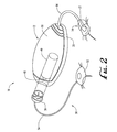
- FIG. 2 illustrates an example of the system 10 in accordance with an embodiment of the present invention.
- the system 10 in accordance with the embodiment illustrated in FIG. 2 includes the delivery device 12 and the sensing device 14 .
- the delivery device 12 in accordance with an embodiment of the present invention includes a disposable housing 20 , a durable housing 30 , and a reservoir 40 .
- the delivery device 12 may further include an infusion path 50 .
- a disposable portion of the delivery device 12 may include the disposable housing 20 and the reservoir 40 .
- the disposable portion of the delivery device 12 may be recommended for disposal after a specified number of uses.
- a durable portion of the delivery device 12 may include the durable housing 30 , electronics (not shown in FIG. 2 ), a drive device having a motor and drive linkage (not shown in FIG. 2 ), and the like. Elements of the durable housing portion of the delivery device 12 are typically not contaminated from contact with the user or the fluidic medium during normal operation of the delivery device 12 and, thus, may be retained for re-use with replaced disposable portions of the delivery device 12 .
- the disposable housing 20 supports the reservoir 40 and has a bottom surface (facing downward and into the page in FIG. 2 ) that is configured to secure to the body of a user.
- An adhesive may be employed at an interface between the bottom surface of the disposable housing 20 and the skin of a user, so as to adhere the disposable housing 20 to the skin of the user.
- the adhesive may be provided on the bottom surface of the disposable housing 20 , with a peelable cover layer covering the adhesive material. In this manner, the cover layer may be peeled off to expose the adhesive material, and the adhesive side of the disposable housing 20 may be placed against the skin of the user.
- the reservoir 40 is configured for containing or holding a fluidic medium, such as, but not limited to insulin.
- the reservoir 40 includes a hollow interior volume for receiving the fluidic medium, such as, but not limited to, a cylinder-shaped volume, a tubular-shaped volume, or the like.
- the reservoir 40 may be provided as a cartridge or canister for containing a fluidic medium.
- the reservoir 40 is able to be refilled with a fluidic medium.
- the reservoir 40 may be supported by the disposable housing 20 in any suitable manner.
- the disposable housing 20 may be provided with projections or struts (not shown), or a trough feature (not shown), for holding the reservoir 40 .
- the reservoir 40 may be supported by the disposable housing 20 in a manner that allows the reservoir 40 to be removed from the disposable housing 20 and replaced with another reservoir.
- the reservoir 40 may be secured to the disposable housing 20 by a suitable adhesive, a strap, or other coupling structure.
- the reservoir 40 includes a port 41 for allowing a fluidic medium to flow into and/or flow out of the interior volume of the reservoir 40 .
- the infusion path 50 includes a connector 56 , a tube 54 , and a needle apparatus 52 .
- the connector 56 of the infusion path 50 may be connectable to the port 41 of the reservoir 40 .
- the disposable housing 20 is configured with an opening near the port 41 of the reservoir 40 for allowing the connector 56 of the infusion path 50 to be selectively connected to and disconnected from the port 41 of the reservoir 40 .
- the port 41 of the reservoir 40 is covered with or supports a septum (not shown in FIG. 2 ), such as a self-sealing septum, or the like.
- the septum may be configured to prevent a fluidic medium from flowing out of the reservoir 40 through the port 41 when the septum is not pierced.
- the connector 56 of the infusion path 50 includes a needle for piercing the septum covering the port 41 of the reservoir 40 so as to allow the fluidic medium to flow out of the interior volume of the reservoir 40 . Examples of needle/septum connectors can be found in U.S.
- the needle apparatus 52 of the infusion path 50 includes a needle that is able to puncture the skin of a user.
- the tube 54 connects the connector 56 with the needle apparatus 52 and is hollow, such that the infusion path 50 is able to provide a path to allow for the delivery of a fluidic medium from the reservoir 40 to the body of a user.
- the durable housing 30 of the delivery device 12 in accordance with various embodiments of the present invention includes a housing shell configured to mate with and secure to the disposable housing 20 .
- the durable housing 30 and the disposable housing 20 may be provided with correspondingly shaped grooves, notches, tabs, or other suitable features, that allow the two parts to easily connect together, by manually pressing the two housings together, by twist or threaded connection, or other suitable manner of connecting the parts that is well known in the mechanical arts.
- the durable housing 30 and the disposable housing 20 may be connected to each other using a twist action.
- the durable housing 30 and the disposable housing 20 may be configured to be separable from each other when a sufficient force is applied to disconnect the two housings from each other.
- the disposable housing 20 and the durable housing 30 may be snapped together by friction fitting.
- a suitable seal such as an o-ring seal, may be placed along a peripheral edge of the durable housing 30 and/or the disposable housing 20 , so as to provide a seal against water entering between the durable housing 30 and the disposable housing 20 .
- the durable housing 30 of the delivery device 12 may support a drive device (not shown in FIG. 2 ), including a motor and a drive device linkage portion, for applying a force to the fluidic medium within the reservoir 40 to force the fluidic medium out of the reservoir 40 and into an infusion path, such as the infusion path 50 , for delivery to a user.
- a drive device (not shown in FIG. 2 ), including a motor and a drive device linkage portion, for applying a force to the fluidic medium within the reservoir 40 to force the fluidic medium out of the reservoir 40 and into an infusion path, such as the infusion path 50 , for delivery to a user.
- an electrically driven motor may be mounted within the durable housing 30 with appropriate linkage for operatively coupling the motor to a plunger arm (not shown in FIG. 2 ) connected to a plunger head (not shown in FIG. 2 ) that is within the reservoir 40 and to drive the plunger head in a direction to force the fluidic medium out of the port 41 of the reservoir 40 and to the
- the motor may be controllable to reverse direction so as to move the plunger arm and the plunger head to cause fluid to be drawn into the reservoir 40 from a patient.
- the motor may be arranged within the durable housing 30 and the reservoir 40 may be correspondingly arranged on the disposable housing 20 , such that the operable engagement of the motor with the plunger head, through the appropriate linkage, occurs automatically upon the user connecting the durable housing 30 with the disposable housing 20 of the delivery device 12 .
- Further examples of linkage and control structures may be found in U.S. patent application Ser. No. 09/813,660, filed Mar. 21, 2001, entitled “Control Tabs for Infusion Devices and Methods of Using the Same”, which is incorporated herein by reference in its entirety.
- the durable housing 30 and the disposable housing 20 may be made of suitably rigid materials that maintain their shape, yet provide sufficient flexibility and resilience to effectively connect together and disconnect, as described above.
- the material of the disposable housing 20 may be selected for suitable compatibility with skin.
- the disposable housing 20 and the durable housing 30 of the delivery device 12 may be made of any suitable plastic, metal, composite material, or the like.
- the disposable housing 20 may be made of the same type of material or a different material relative to the durable housing 30 .
- the disposable housing 20 and the durable housing 30 may be manufactured by injection molding or other molding processes, machining processes, or combinations thereof.
- the disposable housing 20 may be made of a relatively flexible material, such as a flexible silicone, plastic, rubber, synthetic rubber, or the like.
- a relatively flexible material such as a flexible silicone, plastic, rubber, synthetic rubber, or the like.
- the delivery device 12 is connected to the sensing device 14 through a connection element 16 of the sensing device 14 .
- the sensing device 14 may include a sensor 15 that includes any suitable biological or environmental sensing device, depending upon a nature of a treatment to be administered by the delivery device 12 .
- the sensor 15 may include a blood glucose sensor, or the like.
- the sensor 15 may be an external sensor that secures to the skin of a user or, in other embodiments, may be an implantable sensor that is located in an implant site within the body of the user. In further alternatives, the sensor may be included with as a part or along side the infusion cannula and/or needle, such as for example as shown in U.S. patent application Ser. No. 11/149,119, filed Jun. 8, 2005, entitled “Dual Insertion Set”, which is incorporated herein by reference in its entirety.
- the sensor 15 is an external sensor having a disposable needle pad that includes a needle for piercing the skin of the user and enzymes and/or electronics reactive to a biological condition, such as blood glucose level or the like, of the user.
- the delivery device 12 may be provided with sensor data from the sensor 15 secured to the user at a site remote from the location at which the delivery device 12 is secured to the user.
- FIG. 2 While the embodiment shown in FIG. 2 includes a sensor 15 connected by the connection element 16 for providing sensor data to sensor electronics (not shown in FIG. 2 ) located within the durable housing 30 of the delivery device 12 , other embodiments may employ a sensor 15 located within the delivery device 12 . Yet other embodiments may employ a sensor 15 having a transmitter for communicating sensor data by a wireless communication link with receiver electronics (not shown in FIG. 2 ) located within the durable housing 30 of the delivery device 12 . In various embodiments, a wireless connection between the sensor 15 and the receiver electronics within the durable housing 30 of the delivery device 12 may include a radio frequency (RF) connection, an optical connection, or another suitable wireless communication link. Further embodiments need not employ the sensing device 14 and, instead, may provide fluidic medium delivery functions without the use of sensor data.
- RF radio frequency
- the disposable elements may be arranged on the disposable housing 20 , while durable elements may be arranged within a separable durable housing 30 .
- the disposable housing 20 may be separated from the durable housing 30 , so that the disposable housing 20 may be disposed of in a proper manner.
- the durable housing 30 may then be mated with a new (un-used) disposable housing 20 for further delivery operation with a user.
- FIG. 3 illustrates an example of the delivery device 12 in accordance with another embodiment of the present invention.
- the delivery device 12 of the embodiment of FIG. 3 is similar to the delivery device 12 of the embodiment of FIG. 2 . While the delivery device 12 in the embodiment illustrated in FIG. 2 provides for the durable housing 30 to cover the reservoir 40 , the delivery device 12 in the embodiment of FIG. 3 provides for the durable housing 30 to secure to the disposable housing 20 without covering the reservoir 40 .
- the delivery device 12 of the embodiment illustrated in FIG. 3 includes the disposable housing 20 , and the disposable housing 20 in accordance with the embodiment illustrated in FIG. 3 includes a base 21 and a reservoir retaining portion 24 . In one embodiment, the base 21 and reservoir retaining portion 24 may be formed as a single, unitary structure.
- the base 21 of the disposable housing 20 is configured to be secured to the body of a user.
- the reservoir retaining portion 24 of the disposable housing 20 is configured to house the reservoir 40 .
- the reservoir retaining portion 24 of the disposable housing 20 may be configured to have an opening to allow for the port 41 of the reservoir 40 to be accessed from outside of the reservoir retaining portion 24 while the reservoir 40 is housed in the reservoir retaining portion 24 .
- the durable housing 30 may be configured to be attachable to and detachable from the base 21 of the disposable housing 20 .
- the delivery device 12 in the embodiment illustrated in FIG. 3 includes a plunger arm 60 that is connected to or that is connectable to a plunger head (not shown in FIG. 3 ) within the reservoir 40 .
- FIG. 4 illustrates another view of the delivery device 12 of the embodiment of FIG. 3 .
- the delivery device 12 of the embodiment illustrated in FIG. 4 includes the disposable housing 20 , the durable housing 30 , and the infusion path 50 .
- the disposable housing 20 in the embodiment of FIG. 4 includes the base 21 , the reservoir retaining portion 24 , and a peelable cover layer 25 .
- the peelable cover layer 25 may cover an adhesive material on the bottom surface 22 of the base 21 .
- the peelable cover layer 25 may be configured to be peelable by a user to expose the adhesive material on the bottom surface 22 of the base 21 . In some embodiments, there may be multiple adhesive layers on the bottom surface 22 of the base 21 that are separated by peelable layers.
- the infusion path 50 in accordance with the embodiment of the present invention illustrated in FIG. 4 includes the needle 58 rather than the connector 56 , the tube 54 , and the needle apparatus 52 as shown in the embodiment of FIG. 2 .
- the base 21 of the disposable housing 20 may be provided with an opening or pierceable wall in alignment with a tip of the needle 58 , to allow the needle 58 to pass through the base 21 and into the skin of a user under the base 21 , when extended. In this manner, the needle 58 may be used to pierce the skin of the user and deliver a fluidic medium to the user.
- the needle 58 may be extended through a hollow cannula (not shown in FIG. 4 ), such that upon piercing the skin of the user with the needle 58 , an end of the hollow cannula is guided through the skin of the user by the needle 58 . Thereafter, the needle 58 may be removed, leaving the hollow cannula in place, with one end of the cannula located within the body of the user and the other end of the cannula in fluid flow connection with the fluidic medium within the reservoir 40 , to convey pumped infusion media from the reservoir 40 to the body of the user.
- FIG. 5A illustrates a durable portion 8 of the delivery device 12 (refer to FIG. 3 ) in accordance with an embodiment of the present invention.
- FIG. 5B illustrates a section view of the durable portion 8 in accordance with an embodiment of the present invention.
- FIG. 5C illustrates another section view of the durable portion 8 in accordance with an embodiment of the present invention.
- the durable portion 8 includes the durable housing 30 , and a drive device 80 .
- the drive device 80 includes a motor 84 and a drive device linkage portion 82 .
- the durable housing 30 may include an interior volume for housing the motor 84 , the drive device linkage portion 82 , other electronic circuitry, and a power source (not shown in FIGS. 5A , 5 B, and 5 C). Also, in various embodiments, the durable housing 30 is configured with an opening 32 for receiving a plunger arm 60 (refer to FIG. 3 ). Also, in various embodiments, the durable housing 30 may include one or more connection members 34 , such as tabs, insertion holes, or the like, for connecting with the base 21 of the disposable housing 20 (refer to FIG. 3 ).
- FIG. 6A illustrates a disposable portion 9 of the delivery device 12 (refer to FIG. 3 ) in accordance with an embodiment of the present invention.
- FIG. 6B illustrates a section view of the disposable portion 9 in accordance with an embodiment of the present invention.
- FIG. 6C illustrates another section view of the disposable portion 9 in accordance with an embodiment of the present invention.
- the disposable portion 9 includes the disposable housing 20 , the reservoir 40 , the plunger arm 60 , and a plunger head 70 .
- the disposable housing 20 includes the base 21 and the reservoir retaining portion 24 .
- the base 21 includes a top surface 23 having one or more connection members 26 , such as tabs, grooves, or the like, for allowing connections with the one or more connection members 34 of embodiments of the durable housing 30 (refer to FIG. 5B ).
- connection members 26 such as tabs, grooves, or the like
- the reservoir 40 is housed within the reservoir retaining portion 24 of the disposable housing 20 , and the reservoir 40 is configured to hold a fluidic medium.
- the plunger head 70 is disposed at least partially within the reservoir 40 and is moveable within the reservoir 40 to allow the fluidic medium to fill into the reservoir 40 and to force the fluidic medium out of the reservoir 40 .
- the plunger arm 60 is connected to or is connectable to the plunger head 70 . Also, in some embodiments, a portion of the plunger arm 60 extends to outside of the reservoir retaining portion 24 of the disposable housing 20 .
- the plunger arm 60 has a mating portion for mating with the drive device linkage portion 82 of the drive device 80 (refer to FIG. 5C ).
- the durable housing 30 may be snap fitted onto the disposable housing 20 , whereupon the drive device linkage portion 82 automatically engages the mating portion of the plunger arm 60 .
- the motor 84 may be controlled to drive the drive device linkage portion 82 and, thus, move the plunger arm 60 to cause the plunger head 70 to move within the reservoir 40 .
- the plunger head 70 may be moved within the reservoir 40 to force the fluidic medium from the reservoir 40 and into the infusion path, so as to deliver the fluidic medium to the body of the user.
- a user may simply remove the durable housing 30 from the disposable housing 20 , and replace the disposable portion 9 , including the reservoir 40 , with a new disposable portion having a new reservoir.
- the durable housing 30 may be connected to the new disposable housing of the new disposable portion, and the delivery device including the new disposable portion may be secured to the skin of a user.
- the reservoir 40 may be refilled with a fluidic medium.
- the reservoir 40 may be refilled while remaining within the reservoir retaining portion 24 (refer to FIG. 6B ) of the disposable housing 20 .
- the reservoir 40 may be replaced with a new reservoir (not shown), while the disposable housing 20 may be re-used with the new reservoir. In such embodiments, the new reservoir may be inserted into the disposable portion 9 .
- the delivery device 12 includes reservoir status circuitry (not shown), and the reservoir 40 includes reservoir circuitry (not shown).
- the reservoir circuitry stores information such as, but not limited to, at least one of (i) an identification string identifying the reservoir 40 ; (ii) a manufacturer of the reservoir 40 ; (iii) contents of the reservoir 40 ; and (iv) an amount of contents in the reservoir 40 .
- the delivery device 12 includes the reservoir status circuitry (not shown), and the reservoir status circuitry is configured to read data from the reservoir circuitry when the reservoir 40 is inserted into the disposable portion 9 .
- the reservoir status circuitry is further configured to store data to the reservoir circuitry after at least some of the contents of the reservoir 40 have been transferred out of the reservoir 40 , so as to update information in the reservoir circuitry related to an amount of contents still remaining in the reservoir 40 .
- the reservoir status circuitry is configured to store data to the reservoir circuitry, so as to update information in the reservoir circuitry related to an amount of contents still remaining in the reservoir 40 , when the reservoir 40 is inserted into the disposable portion 9 .
- the delivery device 12 includes the reservoir status circuitry (not shown) and the reservoir 40 includes the reservoir circuitry (not shown), and the reservoir status circuitry selectively inhibits use of the delivery device 12 or selectively provides a warning signal based on information read by the reservoir status circuitry from the reservoir circuitry.
- FIG. 7A illustrates a cross-sectional view of a system 100 in accordance with an embodiment of the present invention.
- the system 100 includes a reservoir 110 , a plunger head 120 , a plunger arm 130 , and a septum 140 .
- the system 100 further includes a needle 150 .
- the system 100 may further include similar elements as elements of embodiments of the delivery device 12 (refer to FIGS. 2 and 3 ), in which case the reservoir 110 would correspond to the reservoir 40 (refer to FIGS. 2 , 3 , and 6 C).
- the reservoir 110 may be made of a material, such as but not limited to a suitable metal, plastic, ceramic, glass, composite material, or the like.
- the plunger head 120 may be made of a suitably rigid material such as, but not limited to, metal, plastic, ceramic, glass, composite material, or the like. In various other embodiments, the plunger head 120 may be made of a compressible material such as, but not limited to, an elastically compressible plastic, rubber, silicone, or the like.
- the reservoir 110 includes a reservoir body portion 111 , a body headspace or neck portion 112 , and a curved or sloped portion 117 that connects the reservoir body portion 111 and the neck portion 112 .
- the reservoir 110 has an outer surface 113 and an inner surface 114 .
- the inner surface 114 of the reservoir 110 defines a hollow interior of the reservoir 110 , and the hollow interior of the reservoir 110 is able to contain a fluidic medium.
- the reservoir 110 further includes a port 118 at an end of the neck portion 112 , through which the fluidic medium may be filled into or expelled from the hollow interior of the reservoir 110 .
- the reservoir body portion 111 of the reservoir 110 may have any suitable shape and may have, for example, a cylinder shape, a tube shape, a barrel shape, a spherical shape, a shape with a rectangular cross-section, or the like.
- the neck portion 112 of the reservoir 110 may have any suitable shape and may have, for example, a cylinder shape, a tube shape, a barrel shape, a spherical shape, a shape with a rectangular cross-section, or the like.
- the plunger head 120 is located within the reservoir 110 , and is moveable in an axial direction of the reservoir 110 , to expand or contract an interior volume of the reservoir 110 in which a fluidic medium may be contained.
- the plunger head 120 is connected to the plunger arm 130 , such that movement of the plunger arm 130 in the axial direction of the reservoir 110 causes movement of the plunger head 120 in the axial direction of the reservoir 110 .
- the plunger head 120 includes a plunger body portion 121 , a plunger headspace or neck portion 122 , and a plunger curved or sloped portion 123 that connects the plunger body portion 121 and the plunger neck portion 122 .
- the plunger head 120 further includes one or more seals 125 that surround a portion of the plunger body portion 121 .
- the plunger body portion 121 is shaped such that a contour of an outer surface of the plunger body portion 121 substantially matches or is substantially the same as a contour of an inner surface of the reservoir body portion 111 of the reservoir 110 .
- the plunger body portion 121 has a diameter that is slightly smaller than a diameter of the inner surface of the reservoir body portion 111 of the reservoir 110 , such that the plunger head 120 is able to slide within the reservoir 110 .
- the one or more seals 125 on the plunger body portion 121 are in contact with the inner surface of the reservoir body portion 111 of the reservoir 110 when the plunger head 120 is within the reservoir 110 .
- the plunger neck portion 122 is shaped such that a contour of an outer surface of the plunger neck portion 122 substantially matches or is substantially the same as a contour of an inner surface of the neck portion 112 of the reservoir 110 .
- the plunger neck portion 122 has a diameter that is slightly smaller than a diameter of the inner surface of the neck portion 112 of the reservoir 110 , such that the plunger neck portion 122 is able to slide within the neck portion 112 of the reservoir 110 .
- a diameter of an outer surface of the plunger neck portion 122 closely matches or substantially matches a diameter of an inner surface of the neck portion 112 of the reservoir 110 .
- the plunger neck portion 122 is shaped such that the plunger neck portion 122 substantially fills an area within the neck portion 112 of the reservoir 110 when the plunger head 120 is fully advanced within the reservoir 110 .
- the plunger sloped portion 123 is shaped such that a contour of an outer surface of the plunger sloped portion 123 substantially matches or is substantially the same as a contour of an inner surface of the sloped portion 117 of the reservoir 110 .
- the septum 140 is located at the port 118 of the reservoir 110 .
- the septum 140 may be formed of a suitable material, such as, but not limited to, rubber, silicone rubber, polyurethane, or other materials that may be pierced by a needle and form a seal around a needle.
- the neck portion 112 has a certain length from an end of the sloped portion 117 to the septum 140 .
- the plunger neck portion 122 has a length that is substantially the same as the certain length of the neck portion 112 of the reservoir 110 . In some such embodiments, the plunger neck portion 122 is able to extend substantially all of the way into the neck portion 112 of the reservoir 110 when the plunger head 120 is fully advanced within the reservoir 110 .
- an end of the plunger neck portion 122 may be close to or in contact with the septum 140 when the plunger head 120 is fully advanced within the reservoir 110 .
- a length of the plunger neck portion 122 from an end of the plunger neck portion 122 to the plunger sloped portion 123 substantially matches a length of the neck portion 112 of the reservoir 110 from the septum 140 to the sloped portion 117 of the reservoir 110 .
- the septum 140 is able to be pierced by the needle 150 , such as to allow for a fluidic medium to be passed through the needle 150 and into the hollow interior of the reservoir 110 .
- the plunger head 120 includes a hole or a channel or a relief or a cavity 124 that is able to accommodate a portion of the needle 150 when the plunger head 120 is sufficiently advanced within the reservoir 110 and the septum 140 is pierced by the needle 150 .
- the cavity 124 may have any suitable shape for accommodating a portion of the needle 150 , and may have, for example, a cylindrical shape, a tube shape with a half-sphere bottom, a shape with a rectangular cross-section, or the like.
- a diameter of the cavity 124 is larger than a diameter of the needle 150 , such that an end of the needle 150 is able to fit within the cavity 124 .
- the cavity 124 is in the plunger neck portion 122 of the plunger head 120 .
- a length of the cavity 124 in the plunger neck portion 122 in a direction from the septum 140 toward the plunger body portion 121 is greater than one-quarter of a length of the plunger neck portion 122 .
- the cavity 124 is positioned at a center of an end surface of the plunger neck portion 122 .
- the cavity 124 is positioned off-center at an end surface of the plunger neck portion 122 .
- an end of the neck portion 112 of the reservoir 110 partially covers the septum 140 , such that the needle 150 may only pierce the septum 140 in a location that is aligned with the cavity 124 of the plunger head 120 .
- FIG. 8 illustrates a flowchart for a method in accordance with an embodiment of the present invention.
- the method of FIG. 8 allows for filling the reservoir 110 with a fluidic medium and for expelling the fluidic medium from the reservoir 110 .
- the septum 140 of the reservoir 110 is pierced with the needle 150 , and the method continues to S 11 .
- the plunger head 120 is advanced within the reservoir 110 , such that at least a portion of the needle 150 is received within the cavity 124 of the plunger head 120 .
- the plunger arm 130 may be driven by a motor (not shown in FIG.
- moving the plunger head 120 includes moving the plunger head 120 within the reservoir 110 such that the plunger neck portion 122 extends at least partially into the neck portion 112 of the reservoir 110 (S 12 ). Also, in various embodiments, moving the plunger head 120 includes moving the plunger head 120 within the reservoir 110 such that a portion of the plunger head 120 contacts a portion of the septum 140 (S 13 ). In some embodiments, S 10 and S 11 are performed in a reverse order, such that the plunger head 120 is moved and then the septum 140 is pierced with the needle 150 .
- a portion of the needle 150 may extend into the cavity 124 of the plunger neck portion 122 , which may allow the plunger neck portion 122 to extend substantially all the way to the septum 140 .
- a presence of air pockets between an end of the plunger head 120 and the septum 140 is able to be substantially limited or eliminated when the plunger head 120 is fully advanced within the reservoir 110 . Reducing air pockets between the plunger head 120 and the septum 140 prior to filling the reservoir 110 is beneficial, because it limits an amount of air bubbles that subsequently enter the fluidic medium when the fluidic medium is drawn into the reservoir 110 .
- the method then continues to S 14 .
- the plunger head 120 is retracted within the reservoir 110 to allow a fluidic medium to flow through the needle 150 and into the reservoir 110 .
- the plunger arm 130 may be retracted by a motor (not shown in FIG. 7A ) or by a pulling force exerted by a user to cause the plunger head 120 to retract within the reservoir 110 .
- FIG. 7B illustrates a cross-sectional view of the system 100 in accordance with an embodiment of the present invention when the plunger head 120 has been partially retracted within the reservoir 110 . By retracting the plunger head 120 within the reservoir 110 , the fluidic medium is able to pass through the needle 150 and into the hollow interior of the reservoir 110 .
- one end of the needle 150 may be in the reservoir 110 , and another end of the needle 150 may be in a vial (not shown in FIG. 7B ) or other container that stores the fluidic medium, and the fluidic medium may pass from the vial to the reservoir 110 through the needle 150 .
- the needle 150 is part of a transfer guard or other similar device. Because an amount of air in the reservoir 110 was limited prior to filling the reservoir 110 , an amount of air bubbles in the fluidic medium is also limited when the fluidic medium is filled into the reservoir 110 .
- Limiting or reducing a presence of air bubbles in the fluidic medium is beneficial, because it limits an amount of air bubbles that are later expelled from the reservoir 110 into a patient or user, and thus helps to improve a delivery accuracy when delivering a specified amount of the fluidic medium to a user.
- the method of FIG. 8 may then continue to S 15 in which the needle 150 is removed from the reservoir 110 .
- the septum 140 is a self-healing septum, and when the needle 150 is removed from the reservoir 110 and the septum 140 , the septum 140 closes such that the fluidic medium is contained within the reservoir 110 .
- the method may then continue to S 16 .
- the septum 140 of the reservoir 110 is pierced with another needle.
- the septum 140 of the reservoir 110 may be pierced with a needle of a connector of an infusion path, such as a needle of the connector 56 (refer to FIG. 2 ) of the infusion path 50 (refer to FIG. 2 ).
- the method then continues to S 17 .
- FIG. 7A illustrates the system 100 when the plunger head 120 has been substantially fully advanced within the reservoir 110 .
- the close fitting contour of the plunger head 120 to the interior surface of the reservoir 110 limits or reduces a volume of wasted fluidic medium that remains in the reservoir 110 .
- a presence of air bubbles in a fluidic medium may be limited during filling of the reservoir 110 , and a volume of wasted fluidic medium may be reduced when the fluidic medium is expelled from the reservoir 110 .
- the method then ends in S 18 .
- FIG. 7C illustrates a cross-sectional view from a front direction of the plunger neck portion 122 of the plunger head 120 in accordance with an embodiment of the present invention.
- the plunger neck portion 122 includes the cavity 124 for accommodating a needle.
- the cavity 124 is positioned substantially near a center of a face of the plunger neck portion 122 .
- FIG. 7D illustrates a side view of the plunger head 120 in accordance with an embodiment of the present invention.
- the plunger head 120 includes the plunger body portion 121 , the plunger neck portion 122 , and the plunger sloped portion 123 .
- the plunger body portion 121 includes one or more depressions or cavities 126 in which the one or more seals 125 (refer to FIG. 7A ) may be placed.
- FIGS. 9A , 10 A, 11 A, 12 A, 12 C, 14 A, and 14 B illustrate systems in accordance with various embodiments of the present invention that include reservoirs with geometries that allow for capturing air bubbles so as to reduce a number of air bubbles that are delivered with a fluidic medium.
- Such systems allow for air bubble management since they have bubble trapping shapes and, by reducing a number of air bubbles that are delivered with a fluidic medium, such systems may be able to improve a delivery accuracy when attempting to deliver a specified volume of the fluidic medium.
- Such systems provide reservoir geometries that allow for capturing a greater amount of air bubbles than with standard reservoir geometries, so that the captured air bubbles remain in the reservoir and are not dispensed with the fluidic medium.
- the systems in FIGS. 9A , 10 A, 11 A, 12 A, 12 C, 13 A, 14 A, and 14 B may include similar elements as elements of embodiments of the delivery device 12 (refer to FIGS. 2 and 3 ), in which case the reservoirs in those systems would correspond to the reservoir 40 (refer to FIGS. 2 , 3 , and 6 C).
- reservoirs of the systems in FIGS. 9A , 10 A, 11 A, 12 A, 12 C, 13 A, 14 A, and 14 B may be made of a material, such as but not limited to a suitable metal, plastic, ceramic, glass, composite material, or the like.
- the plunger heads of the systems in those figures may be made of a suitably rigid material such as, but not limited to, metal, plastic, ceramic, glass, composite material, or the like.
- the plunger heads in those systems may be made of a compressible material such as, but not limited to, an elastically compressible plastic, rubber, silicone, or the like.
- FIG. 9A illustrates a cross-sectional view of a system 200 in accordance with an embodiment of the present invention.
- the system 200 includes a reservoir 210 , a plunger head 220 , and a plunger arm 230 .
- the reservoir 210 includes a reservoir body portion 211 , a bubble trap portion 212 , and a port 217 .
- the reservoir 210 has an outer surface 213 and an inner surface 214 .
- the inner surface 214 of the reservoir 210 defines a hollow interior of the reservoir 210 , and the hollow interior of the reservoir 210 is able to contain a fluidic medium.
- the port 217 of the reservoir 210 allows for the fluidic medium to be filled into or expelled from the hollow interior of the reservoir 210 .
- the reservoir body portion 211 of the reservoir 210 may have any suitable shape, such as but not limited to, a cylinder shape, a tube shape, a barrel shape, a spherical shape, a shape with a rectangular cross-section, or the like.
- the plunger head 220 is located within the reservoir 210 , and is moveable in an axial direction of the reservoir 210 , to expand or contract a volume of the reservoir 210 in which a fluidic medium may be contained.
- the plunger head 220 is connected to the plunger arm 230 , such that movement of the plunger arm 230 in the axial direction of the reservoir 210 causes movement of the plunger head 220 in the axial direction of the reservoir 210 .
- the plunger head 220 includes a plunger body portion 221 and a plunger protruding portion 222 .
- the plunger head 220 further includes one or more seals 225 that surround a portion of the plunger body portion 221 .
- the one or more seals 225 may be made of any suitable material, such as but not limited to, rubber, plastic, composite material, or the like.
- the bubble trap portion 212 of the reservoir 210 is shaped to have a volume 216 within an interior of the reservoir 210 , such that air bubbles in a fluidic medium may be trapped in the volume 216 when the fluidic medium is expelled from the reservoir 210 through the port 217 .
- an interior surface of the bubble trap portion 212 is curved or angled near the port 217 , so as to define the volume 216 .
- the bubble trap portion 212 extends from the reservoir body portion 211 of the reservoir 210 past a point 218 of the reservoir 210 where a fluidic medium from an interior volume of the reservoir body portion 211 is able to move into an area or channel 272 of the reservoir 210 that leads to the port 217 .
- the reservoir 210 is shaped such that as the plunger head 220 is advanced within the reservoir 210 , a fluidic medium is able to pass through the port 217 while air bubbles in the reservoir 210 collect in the volume 216 defined by a curved or angled surface of the bubble trap portion 212 of the reservoir 210 .
- a geometry of the reservoir 210 allows for decreasing an amount of air bubbles that are delivered with a fluidic medium as compared with traditional reservoir geometries.
- the bubble trap portion 212 of the reservoir 210 is curved outward from an interior volume defined by the reservoir body portion 211 , and a fluidic medium is able to pass directly from the interior volume defined by the reservoir body portion 211 to the port 217 .
- a surface 215 of the bubble trap portion 212 of the reservoir 210 includes a surface finish or material such that air bubbles substantially do not stick to the surface 215 and are shunted away from the port 217 toward the volume 216 .
- a surface finish or material includes a hydrophobic material, a hydrophilic material, or other suitable material.
- the plunger body portion 221 is shaped such that a contour of the plunger body portion 221 substantially matches or is substantially the same as an inner contour of the reservoir body portion 211 of the reservoir 210 .
- the plunger body portion 221 has a diameter that is slightly smaller than a diameter of the inner surface of the reservoir body portion 211 of the reservoir 210 , such that the plunger head 220 is able to slide within the reservoir 210 .
- a seal 225 on the plunger body portion 221 is in contact with the inner surface of the reservoir body portion 211 of the reservoir 210 when the plunger head 220 is within the reservoir 210 .
- the plunger protruding portion 222 is shaped such that a contour of the plunger protruding portion 222 substantially matches or is substantially the same as an inner contour of the bubble trap portion 212 of the reservoir 210 . In some embodiments, the plunger protruding portion 222 is curved and protrudes from the plunger body portion 221 .
- the plunger protruding portion 222 has a size that is slightly smaller than a region defined by the inner surface of the bubble trap portion 212 of the reservoir 210 , such that the plunger protruding portion 222 is able to slide within the volume 216 of the reservoir 210 , and such that a space for a dead volume of air is left when the plunger head 220 is fully advanced within the reservoir 210 .
- the geometry of the reservoir 210 and the plunger head 220 allow for capturing air bubbles in a volume 216 of the bubble trap portion 212 when a fluidic medium is being expelled from the port 217 of the reservoir 210 .
- the plunger protruding portion 222 has a size such that when the plunger head 220 is fully advanced within the reservoir 210 , the plunger protruding portion 222 substantially fills the volume 216 of the bubble trap portion 212 . Also, in various embodiments, the plunger protruding portion 222 fills less than all of the volume 216 of the bubble trap portion 212 when the plunger head 220 is fully advanced within the reservoir 210 , so that one or more air pockets for holding air exist between the plunger protruding portion 222 and an inner surface of the bubble trap portion 212 when the plunger head 220 is fully advanced within the reservoir 210 . In some embodiments, the plunger protruding portion 222 extends at least partially into the volume 216 of the bubble trap portion 212 when the plunger head 220 is sufficiently advanced within the reservoir 210 .
- FIG. 9B illustrates a cross-sectional view of the reservoir 210 in accordance with an embodiment of the present invention.
- FIG. 9B is shaded to highlight various features of the reservoir 210 .
- the reservoir 210 includes the reservoir body portion 211 , the bubble trap portion 212 , and the port 217 .
- the reservoir body portion 211 has an interior volume 270 for containing a fluidic medium.
- the port 217 is in fluid flow communication with the interior volume 270 of the reservoir body portion 211 .
- the bubble trap portion 212 has the volume 216 in fluid flow communication with the interior volume 270 of the reservoir body portion 211 for trapping air bubbles that are in the fluidic medium as the fluidic medium is being expelled from the interior volume 270 .
- the port 217 is located to a particular side of the interior volume 270
- the bubble trap portion 212 is located to the particular side of the interior volume 270
- the bubble trap portion 212 has a first portion 281 that extends from the reservoir body portion 211 away from the interior volume 270 , and a second portion 282 that returns back toward the interior volume 270 .
- the reservoir body portion 211 and the bubble trap portion 212 are formed together as a single seamless unit.
- the first portion 281 of the bubble trap portion 212 extends from the reservoir body portion 211 away from the interior volume 270 and the second portion 282 of the bubble trap portion 212 extends from the first portion 281 toward the interior volume 270 .
- the bubble trap portion 212 includes a curved surface 283 having a first end region 284 , a second end region 285 , and a middle region 286 between the first end region 284 and the second end region 285 .
- the first end region 284 and the second end region 285 are closer to the interior volume 270 of the reservoir body portion 211 than the middle region 286 is to the interior volume 270 .
- the first end region 284 is in contact with the reservoir body portion 211
- the second end region 285 is located adjacent to the interior volume 270 of the reservoir body portion 211 .
- the curved surface 283 of the bubble trap portion 212 is in contact with the fluidic medium when the fluidic medium is in the volume 216 of the bubble trap portion 212 .
- the curved surface 283 is approximately U-shaped.
- FIG. 9B illustrates a cross-sectional view, but in three-dimensions the bubble trap portion 212 may be shaped, for example, approximately as a semi-toroid.
- the reservoir 210 is shaped such that in order for a fluidic medium to flow from the volume 216 of the bubble trap portion 212 to the port 217 , the fluidic medium must flow through the interior volume 270 of the reservoir body portion 211 .
- the reservoir 210 includes the channel 272 that leads from the interior volume 270 of the reservoir body portion 211 to the port 217 , and the bubble trap portion 212 encircles at least a portion of the channel 272 .
- FIG. 10A illustrates a cross-sectional view of a system 300 in accordance with an embodiment of the present invention.
- the system 300 includes a reservoir 310 , a plunger head 320 , and a plunger arm 330 .
- the reservoir 310 includes a reservoir body portion 311 , a bubble trap portion 312 , and a port 317 .
- the reservoir 310 has an outer surface 313 and an inner surface 314 .
- the inner surface 314 of the reservoir 310 defines a hollow interior of the reservoir 310 , and the hollow interior of the reservoir 310 is able to contain a fluidic medium.
- the port 317 of the reservoir 310 allows for the fluidic medium to be filled into or expelled from the hollow interior of the reservoir 310 .
- the reservoir body portion 311 of the reservoir 310 may have any suitable shape, such as but not limited to, a cylinder shape, a tube shape, a barrel shape, a spherical shape, a shape with a rectangular cross-section, or the like.
- the plunger head 320 is located within the reservoir 310 , and is moveable in an axial direction of the reservoir 310 , to expand or contract a volume of the reservoir 310 in which a fluidic medium may be contained.
- the plunger head 320 is connected to the plunger arm 330 , such that movement of the plunger arm 330 in the axial direction of the reservoir 310 causes movement of the plunger head 320 in the axial direction of the reservoir 310 .
- the plunger head 320 includes a plunger body portion 321 and a plunger protruding portion 322 .
- the plunger head 320 further includes one or more seals 325 that surround a portion of the plunger body portion 321 .
- the bubble trap portion 312 of the reservoir 310 is shaped so as to form a volume 316 within an interior of the reservoir 310 , such that air bubbles in a fluidic medium may be trapped in the volume 316 of the bubble trap portion 312 when the fluidic medium is expelled from the reservoir 310 through the port 317 .
- an interior surface of the bubble trap portion 312 is angled at a substantially straight angle near the port 317 , so as to define the volume 316 .
- the bubble trap portion 312 extends from the reservoir body portion 311 of the reservoir 310 past a point 318 of the reservoir 310 where a fluidic medium from an interior volume of the reservoir body portion 311 is able to move into an area or channel 372 of the reservoir 310 that leads to the port 317 .
- the reservoir 310 is shaped such that as the plunger head 320 is advanced within the reservoir 310 , a fluidic medium is able to pass through the port 317 while air bubbles in the reservoir 310 collect in the volume 316 defined by a substantially straight angled surface of the bubble trap portion 312 of the reservoir 310 .
- a geometry of the reservoir 310 may allow for decreasing an amount of air bubbles that are delivered with a fluidic medium as compared with traditional reservoir geometries.
- the bubble trap portion 312 of the reservoir 310 is angled outward from an interior region of the reservoir 310 defined by the reservoir body portion 311 , and a fluidic medium is able to pass directly from the interior region of the reservoir 310 defined by the reservoir body portion 311 to the port 317 .
- a surface 315 of the bubble trap portion 312 of the reservoir 310 includes a surface finish or material such that air bubbles substantially do no stick to the surface 315 and are shunted away from the port 317 toward the volume 316 .
- the plunger body portion 321 is shaped such that a contour of the plunger body portion 321 substantially matches or is substantially the same as a contour of an inner surface of the reservoir body portion 311 of the reservoir 310 .
- the plunger body portion 321 has a diameter that is slightly smaller than a diameter of the inner surface of the reservoir body portion 311 of the reservoir 310 , such that the plunger head 320 is able to slide within the reservoir 310 .
- the one or more seals 325 on the plunger body portion 321 are in contact with the inner surface of the reservoir body portion 311 of the reservoir 310 when the plunger head 320 is within the reservoir 310 .
- the plunger protruding portion 322 is shaped such that a contour of the plunger protruding portion 322 substantially matches or is substantially the same as an inner contour of the bubble trap portion 312 of the reservoir 310 . In some embodiments, the plunger protruding portion 322 is angled from the plunger body portion 321 at a substantially straight angle and protrudes from the plunger body portion 321 .
- the plunger protruding portion 322 has a size that is slightly smaller than a region defined by the inner surface of the bubble trap portion 312 of the reservoir 310 , such that the plunger protruding portion 322 is able to slide within the volume 316 of the bubble trap portion 312 , and such that a space for a dead volume of air is left when the plunger head 320 is fully advanced within the reservoir 310 .
- the geometry of the reservoir 310 and the plunger head 320 allow for capturing air bubbles in a volume 316 of the bubble trap portion 312 when a fluidic medium is being expelled from the port 317 of the reservoir 310 .
- the plunger protruding portion 322 has a size such that when the plunger head 320 is fully advanced within the reservoir 310 , the plunger protruding portion 322 substantially fills the volume 316 of the bubble trap portion 312 . Also, in various embodiments, the plunger protruding portion 322 fills less than all of the volume 316 of the bubble trap portion 312 when the plunger head 320 is fully advanced within the reservoir 310 , so that one or more air pockets for holding air exist between the plunger protruding portion 322 and an inner surface of the bubble trap portion 312 when the plunger head 320 is fully advanced within the reservoir 310 . In some embodiments, the plunger protruding portion 322 extends at least partially into the volume 316 of the bubble trap portion 312 when the plunger head 320 is sufficiently advanced within the reservoir 310 .
- FIG. 10B illustrates a cross-sectional view of the reservoir 310 in accordance with an embodiment of the present invention.
- FIG. 10B is shaded to highlight various features of the reservoir 310 .
- the reservoir 310 includes the reservoir body portion 311 , the bubble trap portion 312 , and the port 317 .
- the reservoir body portion 311 has an interior volume 370 for containing a fluidic medium.
- the port 317 is in fluid flow communication with the interior volume 370 of the reservoir body portion 311 .
- the bubble trap portion 312 has the volume 316 in fluid flow communication with the interior volume 370 of the reservoir body portion 311 for trapping air bubbles that are in the fluidic medium as the fluidic medium is being expelled from the interior volume 370 .
- the port 317 is located to a particular side of the interior volume 370
- the bubble trap portion 312 is located to the particular side of the interior volume 370
- the bubble trap portion 312 has a first portion 381 that extends from the reservoir body portion 311 away from the interior volume 370 , and a second portion 382 that returns back toward the interior volume 370 .
- the reservoir body portion 311 and the bubble trap portion 312 are formed together as a single seamless unit.
- the first portion 381 of the bubble trap portion 312 extends from the reservoir body portion 311 away from the interior volume 370 and the second portion 382 of the bubble trap portion 312 extends from the first portion 381 toward the interior volume 370 .
- the reservoir 310 is shaped such that in order for a fluidic medium to flow from the volume 316 of the bubble trap portion 312 to the port 317 , the fluidic medium must flow through the interior volume 370 of the reservoir body portion 311 .
- the reservoir 310 includes the channel 372 that leads from the interior volume 370 of the reservoir body portion 311 to the port 317 , and the bubble trap portion 312 encircles at least a portion of the channel 372 .
- the bubble trap portion 312 includes a first surface 383 that defines an edge of the volume 316 of the bubble trap portion 312 , and a second surface 384 that defines another edge of the volume 316 of the bubble trap portion 312 , where the second surface 384 is positioned at an angle with respect to the first surface 383 .
- the angle between the first surface 383 and the second surface 384 is less than 90 degrees.
- the first surface 383 is planar with respect to an inner surface of the reservoir body portion 311 of the reservoir 310 .
- the port 317 is located to a particular side of the interior volume 370 and the first portion 381 of the bubble trap portion 312 extends from the reservoir body portion 311 to the particular side.
- FIG. 11A illustrates a cross-sectional view of a system 400 in accordance with an embodiment of the present invention.
- the system 400 includes a reservoir 410 , a plunger head 420 , and a plunger arm 430 .
- the reservoir 410 includes a reservoir body portion 411 , a bubble trap portion 412 , and a port 417 .
- the reservoir 410 has an outer surface 413 and an inner surface 414 .
- the inner surface 414 of the reservoir 410 defines a hollow interior of the reservoir 410 , and the hollow interior of the reservoir 410 is able to contain a fluidic medium.
- the port 417 of the reservoir 410 allows for the fluidic medium to be filled into or expelled from the hollow interior of the reservoir 410 .
- the reservoir body portion 411 of the reservoir 410 may have any suitable shape, such as but not limited to, a cylinder shape, a tube shape, a barrel shape, a spherical shape, a shape with a rectangular cross-section, or the like.
- the plunger head 420 is located within the reservoir 410 , and is moveable in an axial direction of the reservoir 410 , to expand or contract a volume of the reservoir 410 in which a fluidic medium may be contained.
- the plunger head 420 is connected to the plunger arm 430 , such that movement of the plunger arm 430 in the axial direction of the reservoir 410 causes movement of the plunger head 420 in the axial direction of the reservoir 410 .
- the plunger head 420 includes a plunger body portion 421 and a plunger protruding portion 422 .
- the plunger head 420 further includes one or more seals 425 that surround a portion of the plunger body portion 421 .
- the bubble trap portion 412 of the reservoir 410 is shaped so as to form a volume 416 within an interior of the reservoir 410 , such that air bubbles in a fluidic medium may be trapped in the volume 416 of the bubble trap portion 412 when the fluidic medium is expelled from the reservoir 410 through the port 417 .
- the reservoir 410 is shaped such that as the plunger head 420 is advanced within the reservoir 410 , a fluidic medium is able to pass through the port 417 while air bubbles in the reservoir 410 collect in the volume 416 of the reservoir 410 .
- Such a geometry of the reservoir 410 may allow for decreasing an amount of air bubbles that are delivered with a fluidic medium as compared with traditional reservoir geometries.
- the plunger body portion 421 is shaped such that a contour of an outer surface of the plunger body portion 421 substantially matches or is substantially the same as a contour of an inner surface of the reservoir body portion 411 of the reservoir 410 .
- the plunger body portion 421 has a diameter that is slightly smaller than a diameter of the inner surface of the reservoir body portion 411 of the reservoir 410 , such that the plunger head 420 is able to slide within the reservoir 410 .
- the one or more seals 425 on the plunger body portion 421 are in contact with the inner surface of the reservoir body portion 411 of the reservoir 410 when the plunger head 420 is within the reservoir 410 .
- the plunger protruding portion 422 is shaped such that a contour of an outer surface of the plunger protruding portion 422 substantially matches or is substantially the same as a contour of an inner surface of the bubble trap portion 412 of the reservoir 410 .
- FIG. 11B illustrates a cross-sectional view of the reservoir 410 in accordance with an embodiment of the present invention.
- FIG. 11B is shaded to highlight various features of the reservoir 410 .
- the reservoir 410 includes the reservoir body portion 411 , the bubble trap portion 412 , and the port 417 .
- the reservoir body portion 411 has an interior volume 470 for containing a fluidic medium.
- the port 417 is in fluid flow communication with the interior volume 470 of the reservoir body portion 411 .
- the bubble trap portion 412 has the volume 416 in fluid flow communication with the interior volume 470 of the reservoir body portion 411 for trapping air bubbles that are in the fluidic medium as the fluidic medium is being expelled from the interior volume 470 .
- the port 417 is located to a particular side of the interior volume 470
- the bubble trap portion 412 is located to the particular side of the interior volume 470
- the bubble trap portion 412 has a first portion 481 that extends from the reservoir body portion 411 away from the interior volume 470 , and a second portion 482 that returns back toward the interior volume 470 .
- the reservoir body portion 411 and the bubble trap portion 412 are formed together as a single seamless unit.
- the first portion 481 of the bubble trap portion 412 extends from the reservoir body portion 411 away from the interior volume 470 and the second portion 482 of the bubble trap portion 412 extends from the first portion 481 toward the interior volume 470 .
- the bubble trap portion 412 includes a curved surface 483 .
- the curved surface 483 of the bubble trap portion 412 is in contact with the fluidic medium when the fluidic medium is in the volume 416 of the bubble trap portion 412 .
- the reservoir 410 is shaped such that in order for a fluidic medium to flow from the volume 416 of the bubble trap portion 412 to the port 417 , the fluidic medium must flow through the interior volume 470 of the reservoir body portion 411 .
- the reservoir 410 includes a channel 472 that leads from the interior volume 470 of the reservoir body portion 411 to the port 417 , and the bubble trap portion 412 encircles at least a portion of the channel 472 .
- the plunger protruding portion 422 is shaped such that a contour of the plunger protruding portion 422 substantially matches or is substantially the same as an inner contour of the bubble trap portion 412 of the reservoir 410 .
- the plunger protruding portion 422 is at least partially curved and protrudes from the plunger body portion 421 .
- the plunger protruding porting includes a surface that is substantially parallel to an inner surface of the reservoir body portion 411 of the reservoir 410 .
- the plunger protruding portion 422 has a size that is slightly smaller than a region defined by the inner surface of the bubble trap portion 412 of the reservoir 410 , such that the plunger protruding portion 422 is able to slide within the volume 416 of the reservoir 410 , and such that a space for a dead volume of air is left when the plunger head 420 is fully advanced within the reservoir 410 .
- the geometry of the reservoir 410 and the plunger head 420 allow for capturing air bubbles in a volume 416 of the bubble trap portion 412 when a fluidic medium is being expelled from the port 417 of the reservoir 410 .
- the plunger protruding portion 422 has a size such that when the plunger head 420 is fully advanced within the reservoir 410 , the plunger protruding portion 422 substantially fills the volume 416 of the bubble trap portion 412 . Also, in various embodiments, the plunger protruding portion 422 fills less than all of the volume 416 of the bubble trap portion 412 when the plunger head 420 is fully advanced within the reservoir 410 , so that one or more air pockets for holding air exist between the plunger protruding portion 422 and an inner surface of the bubble trap portion 412 when the plunger head 420 is fully advanced within the reservoir 410 . In some embodiments, the plunger protruding portion 422 extends at least partially into the volume 416 of the bubble trap portion 412 when the plunger head 420 is sufficiently advanced within the reservoir 410 .
- FIG. 12A illustrates a cross-sectional view of a system 500 in accordance with an embodiment of the present invention.
- the system 500 includes a reservoir 510 , a plunger head 520 , and a plunger arm 530 .
- the system 500 further includes a needle 550 .
- the reservoir 510 is similar to the reservoir 210 of the system 200 (refer to FIG. 9A ), and includes a reservoir body portion 511 and a bubble trap portion 512 .
- the bubble trap portion 512 defines a volume 516 for trapping air bubbles.
- the reservoir 510 has an air trap geometry that allows for capturing air bubbles.
- the plunger head 520 is similar to the plunger head 220 of the system 200 (refer to FIG. 9A ).
- the plunger head 520 includes a plunger body portion 521 and a plunger protruding portion 522 .
- the plunger head 520 further includes a depression or relief 523 for allowing at least a portion of the needle 550 to be inserted into an interior of the reservoir 510 when the plunger head 520 is fully advanced within the reservoir 510 .
- the plunger head 520 has the relief 523 for receiving at least a portion of the needle 550 when the plunger head 520 is sufficiently advanced within the reservoir 510 and the portion of the needle 550 is inserted into the reservoir 510 .
- the reservoir 510 is shaped to trap air bubbles. Also, in various embodiments, the reservoir 510 and the plunger head 520 are shaped so as to minimize a delivery of air bubbles when a fluidic medium is expelled from the reservoir 510 .
- FIG. 12B illustrates a cross-sectional view of the reservoir 510 in accordance with an embodiment of the present invention.
- FIG. 12B is shaded to highlight various features of the reservoir 510 .
- the reservoir 510 includes the reservoir body portion 511 , the bubble trap portion 512 , and a port 517 .
- the reservoir body portion 511 has an interior volume 570 for containing a fluidic medium.
- the port 517 is in fluid flow communication with the interior volume 570 of the reservoir body portion 511 .
- the bubble trap portion 512 has the volume 516 in fluid flow communication with the interior volume 570 of the reservoir body portion 511 for trapping air bubbles that are in the fluidic medium as the fluidic medium is being expelled from the interior volume 570 .
- the port 517 is located to a particular side of the interior volume 570
- the bubble trap portion 512 is located to the particular side of the interior volume 570
- the bubble trap portion 512 has a first portion 581 that extends from the reservoir body portion 511 away from the interior volume 570 , and a second portion 582 that returns back toward the interior volume 570 .
- the reservoir body portion 511 and the bubble trap portion 512 are formed together as a single seamless unit.
- the first portion 581 of the bubble trap portion 512 extends from the reservoir body portion 511 away from the interior volume 570 and the second portion 582 of the bubble trap portion 512 extends from the first portion 581 toward the interior volume 570 .
- the bubble trap portion 512 includes a curved surface 583 having a first end region 584 , a second end region 585 , and a middle region 586 between the first end region 584 and the second end region 585 .
- the first end region 584 and the second end region 585 are closer to the interior volume 570 of the reservoir body portion 511 than the middle region 586 is to the interior volume 570 .
- the first end region 584 is in contact with the reservoir body portion 511
- the second end region 585 is located adjacent to the interior volume 570 of the reservoir body portion 511 .
- the curved surface 583 of the bubble trap portion 512 is in contact with the fluidic medium when the fluidic medium is in the volume 516 of the bubble trap portion 512 .
- the curved surface 583 is approximately U-shaped.
- FIG. 9B illustrates a cross-sectional view, but in three-dimensions the bubble trap portion 512 may be shaped, for example, approximately as a semi-toroid.
- the reservoir 510 is shaped such that in order for a fluidic medium to flow from the volume 516 of the bubble trap portion 512 to the port 517 , the fluidic medium must flow through the interior volume 570 of the reservoir body portion 511 .
- the reservoir 510 includes a channel 572 that leads from the interior volume 570 of the reservoir body portion 511 to the port 517 , and the bubble trap portion 512 encircles at least a portion of the channel 572 .
- FIG. 12C illustrates a cross-sectional view of the system 500 of FIG. 12A in accordance with another embodiment of the present invention.
- the system 500 further includes a feature 560 .
- the feature 560 is located between an interior surface 515 of the bubble trap portion 512 of the reservoir 510 and a location of the reservoir 510 where a fluidic medium is able to be expelled from the reservoir 510 .
- the feature 560 may comprise, for example, a hydrophilic material or a hydrophobic material, that will substantially keep air bubbles from being dispensed through the port 517 of the reservoir 510 .
- the feature 560 shunts air bubbles in a fluidic medium away from the port 517 of the reservoir 510 and toward the volume 516 of the bubble trap portion 512 when the fluidic medium is being expelled from an interior volume of the reservoir body portion 511 of the reservoir 510 .
- FIG. 13A illustrates a cross-sectional view of a system 600 in accordance with an embodiment of the present invention.
- the system 600 includes a reservoir 610 , a plunger head 620 , and a plunger arm 630 .
- the reservoir 610 has a hollow interior that is able to contain a fluidic medium.
- the reservoir 610 includes a port 617 that allows for the fluidic medium to be filled into or expelled from the hollow interior of the reservoir 610 .
- a septum 640 is located in the port 617 of the reservoir 610 , where the septum 640 is able to be pierced by a needle 650 .
- the reservoir 610 includes a reservoir body portion 611 that may have any suitable shape, such as but not limited to, a cylinder shape, a tube shape, a barrel shape, a spherical shape, a shape with a rectangular cross-section, or the like.
- the plunger head 620 is located within the reservoir 610 , and is moveable in an axial direction of the reservoir 610 , to expand or contract a volume of the reservoir 610 in which a fluidic medium may be contained.
- the plunger head 620 is connected to the plunger arm 630 , such that movement of the plunger arm 630 in the axial direction of the reservoir 610 causes movement of the plunger head 620 in the axial direction of the reservoir 610 .
- the plunger head 620 is shaped to form a bubble trap region 625 for trapping air bubbles that are in the fluidic medium as the fluidic medium is expelled from the reservoir 610 by the plunger head 620 .
- the plunger head 620 includes a concave portion 624 that defines the bubble trap region 625 .
- the plunger head 620 further includes one or more seals 626 that surround a portion of the plunger head 620 .
- the one or more seals 626 may be made of any suitable material, such as but not limited to, rubber, plastic, composite material, or the like.
- the plunger head 620 includes a body portion 621 , a first protrusion portion 622 protruding from the body portion 621 , and a second protrusion portion 623 protruding from the body portion 621 .
- the bubble trap region 625 is located between the first protrusion portion 622 and the second protrusion portion 623 .
- FIG. 13A is a cross-sectional view, and that the plunger head 620 is actually a three-dimensional object as rotated around a central axis passing in an axial direction of the reservoir 610 .
- the first protrusion portion 622 surrounds at least a portion of the second protrusion portion 623 .
- FIG. 13B illustrates a cross-sectional view of the plunger head 620 in accordance with an embodiment of the present invention.
- the first protrusion portion 622 extends a first distance 682 from the body portion 621 .
- the second protrusion portion 623 extends a second distance 683 from the body portion 621 .
- the first distance 682 is greater than the second distance 683 .
- the second distance 683 is greater than one-fourth of the first distance 682 .
- the second protrusion portion 623 is dome shaped.
- the concave portion 624 of the plunger head 620 includes a curved surface that defines the bubble trap region 625 .
- the curved surface of the concave portion 624 has a first end position 672 , a second end position 673 , and an innermost position 671 .
- the first end position 672 is located on the first protrusion portion 622
- the second end position 673 is located on the second protrusion portion 623 .
- the innermost position 671 is located at an innermost position of the concave portion 624 with respect to a depth 680 of the plunger head 620 .
- a depth 684 of the bubble trap region 625 defined by the concave portion 624 is at least greater than one-half of a width 685 of the bubble trap region 625 from the first end position 672 to the second end position 673 . In various embodiments, the depth 684 of the bubble trap region 625 is greater than or equal to one-fourth of the depth 680 of the plunger head 620 . In various embodiments, the body portion 621 of the plunger head 620 has a depth 686 and a width 681 . In various embodiments, the plunger head 620 includes one or more seal recesses 627 in which the seals 626 are located.
- a method for expelling a fluidic medium from a reservoir in accordance with an embodiment of the present invention may be performed using the system 600 .
- the plunger head 620 includes the concave portion 624 that defines the bubble trap region 625 .
- the method includes expelling the fluidic medium from the reservoir 610 using the plunger head 620 , and trapping, in the bubble trap region 625 defined by the concave portion 624 of the plunger head 620 , air bubbles that are in the fluidic medium as the fluidic medium is being expelled from the reservoir 610 by the plunger head 620 .
- the fluidic medium expelled from the reservoir 610 is delivered to a body of a patient through the needle 650 .
- FIG. 14A illustrates a cross-sectional view of a system 800 in accordance with an embodiment of the present invention.
- the system 800 allows for delivering a fluidic medium, such as to a body of a patient.
- the system 800 includes a reservoir 810 , a plunger head 820 , and a plunger arm 830 .
- the reservoir 810 includes a reservoir body portion 811 , a reservoir bubble trap portion 812 , and a port 817 .
- the reservoir 810 has a hollow interior, and the hollow interior of the reservoir 810 is able to contain a fluidic medium.
- the port 817 of the reservoir 810 allows for the fluidic medium to be filled into or expelled from the hollow interior of the reservoir 810 .
- the reservoir body portion 811 of the reservoir 810 may have any suitable shape, such as but not limited to, a cylinder shape, a tube shape, a barrel shape, a spherical shape, a shape with a rectangular cross-section, or the like.
- the plunger head 820 is located within the reservoir 810 , and is moveable in an axial direction of the reservoir 810 , to expand or contract a volume of the reservoir 810 in which a fluidic medium may be contained.
- the plunger head 820 is connected to the plunger arm 830 , such that movement of the plunger arm 830 in the axial direction of the reservoir 810 causes movement of the plunger head 820 in the axial direction of the reservoir 810 .
- the plunger head 820 is shaped to form a bubble trap region 825 for trapping air bubbles that are in the fluidic medium as the fluidic medium is expelled from the reservoir 810 by the plunger head 820 .
- the plunger head 820 includes a concave portion 824 that defines the bubble trap region 825 .
- the plunger head 820 includes a body portion 821 , a first protrusion portion 822 protruding from the body portion 821 , and a second protrusion portion 823 protruding from the body portion 821 .
- the bubble trap region 825 is located between the first protrusion portion 822 and the second protrusion portion 823 .
- FIG. 14A is a cross-sectional view, and that the plunger head 820 is actually a three-dimensional object as rotated around a central axis passing in an axial direction of the reservoir 810 .
- the first protrusion portion 822 surrounds at least a portion of the second protrusion portion 823 .
- the first protrusion portion 822 extends a first distance from the body portion 821 .
- the second protrusion portion 823 extends a second distance from the body portion 821 .
- the first distance is greater than the second distance.
- the second distance is greater than one-fourth of the first distance.
- the second protrusion portion 823 is dome shaped.
- the concave portion 824 of the plunger head 820 includes a curved surface that defines the bubble trap region 825 .
- the curved surface of the concave portion 824 has a first end position, a second end position, and an innermost position.
- the first end position is located on the first protrusion portion 822
- the second end position is located on the second protrusion portion 823 .
- the innermost position is located at an innermost position of the concave portion 824 with respect to a depth of the plunger head 820 .
- a depth of the bubble trap region 825 defined by the concave portion 824 is at least greater than one-half of a width of the bubble trap region 825 from the first end position to the second end position.
- the depth of the bubble trap region 825 is greater than or equal to one-fourth of the depth of the plunger head 820 .
- the reservoir bubble trap portion 812 of the reservoir 810 is shaped to have a volume 816 within an interior of the reservoir 810 , such that air bubbles in the fluidic medium may be trapped in the volume 816 when the fluidic medium is expelled from the reservoir 810 through the port 817 .
- an interior surface 815 of the reservoir bubble trap portion 812 is curved or angled near the port 817 , so as to define the volume 816 .
- reservoir the bubble trap portion 812 extends from the reservoir body portion 811 of the reservoir 810 past a point of the reservoir 810 where the fluidic medium from an interior volume of the reservoir body portion 811 is able to move into an area or channel 872 of the reservoir 810 that leads to the port 817 .
- the reservoir 810 and the plunger head 820 are shaped such that as the plunger head 820 is advanced within the reservoir 810 , the fluidic medium is able to pass through the port 817 while some air bubbles in the reservoir 810 collect in the volume 816 defined by the interior surface 815 of the reservoir bubble trap portion 812 of the reservoir 810 and other air bubbles in the reservoir 810 collect in the bubble trap region 825 defined by the concave portion 824 of the plunger head 820 .
- Such a geometry of the reservoir 810 and the plunger head 820 allows for decreasing an amount of air bubbles that are delivered with a fluidic medium as compared with traditional reservoir and plunger head geometries.
- the reservoir bubble trap portion 812 of the reservoir 810 is curved outward from an interior volume 870 defined by the reservoir body portion 811 , and a fluidic medium is able to pass directly from the interior volume 870 defined by the reservoir body portion 811 to the port 817 .
- the body portion 821 of the plunger head 820 is shaped such that a contour of the body portion 821 substantially matches or is substantially the same as an inner contour of the reservoir body portion 811 of the reservoir 810 .
- the body portion 821 of the plunger head 820 has a diameter that is slightly smaller than a diameter of an inner surface of the reservoir body portion 811 of the reservoir 810 , such that the plunger head 820 is able to slide within the reservoir 810 .
- a seal 826 on the body portion 821 of the plunger head 820 is in contact with the inner surface of the reservoir body portion 811 of the reservoir 810 when the plunger head 820 is within the reservoir 810 .
- the reservoir body portion 811 has the interior volume 870 for containing the fluidic medium.
- the port 817 is in fluid flow communication with the interior volume 870 .
- the plunger head 820 is moveable within the reservoir 810 , and the plunger head 820 is shaped to form the bubble trap region 825 for trapping air bubbles that are in the fluidic medium as the fluidic medium is being expelled from the interior volume 870 through the port 817 by the plunger head 820 .
- the geometry of the reservoir 810 and the plunger head 820 allow for capturing some air bubbles in the volume 816 of the reservoir bubble trap portion 812 and for capturing some air bubbles in the bubble trap region 825 defined by the plunger head 820 when the fluidic medium is being expelled through the port 817 of the reservoir 810 .
- the reservoir includes the reservoir bubble trap portion 812 having the volume 816 in fluid flow communication with the interior volume 870 for trapping air bubbles that are in the fluidic medium as the fluidic medium is being expelled from the interior volume 870 .
- a contour of the first protrusion portion 822 of the plunger head 820 substantially matches an inner contour of the reservoir bubble trap portion 812 .
- the first protrusion portion 822 of the plunger head 820 is shaped and positioned such that the first protrusion portion 822 extends at least partially into the volume 816 of the reservoir bubble trap portion 812 when the plunger head 820 is sufficiently advanced within the reservoir 810 .
- the first protrusion portion 822 of the plunger head 820 is shaped and positioned such that when the plunger head 820 is fully advanced within the reservoir 810 the first protrusion portion 822 substantially fills the volume 816 of the reservoir bubble trap portion 812 .
- the reservoir 810 is shaped such that in order for the fluidic medium to flow from the volume 816 of the reservoir bubble trap portion 812 to the port 817 , the fluidic medium must flow through the interior volume 870 .
- the reservoir 810 further includes the channel 872 that leads from the interior volume 870 to the port 817 .
- the reservoir bubble trap portion 812 includes a first portion that extends from the reservoir body portion 811 away from the interior volume 870 , and a second portion that returns back toward the interior volume 870 , where the reservoir bubble trap portion 812 encircles at least a portion of the channel 872 .
- the system 800 further includes the drive device 80 , the disposable housing 20 , and the durable housing 30 , where the reservoir 810 of FIG. 14A may correspond to the reservoir 40 of FIG. 3 .
- the drive device 80 includes the drive device linkage portion 82 and the motor 84 for moving the drive device linkage portion 82 .
- the plunger arm 830 is connected to the plunger head 820 , and the plunger arm 830 has a mating portion, which may include threads, teeth, or the like, for mating with the drive device linkage portion 82 of the drive device 80 .
- the disposable housing 20 allows for housing the reservoir 810 and for being secured to a user, such as the user 7 of FIG. 1 .
- the durable housing 30 allows for housing the motor 84 of the drive device 80 , where the durable housing 30 is configured to be selectively engaged with and disengaged from the disposable housing 20 .
- FIG. 14B illustrates the system 800 in accordance with an embodiment of the present invention.
- the second protrusion portion 823 of the plunger head 820 includes a cavity 828 for receiving a portion of a needle 850 when the plunger head 820 is sufficiently advanced within the reservoir 810 .
- the second protrusion portion 823 is aligned with the port 817 , such that when the needle 850 is inserted into the port 817 , an end 852 of the needle 850 is directed toward the second protrusion portion 823 .
- the reservoir 810 includes a material 860 for shunting air bubbles in the fluidic medium away from the port 817 and toward the volume 816 of the reservoir bubble trap portion 812 when the fluidic medium is being expelled from the interior volume 870 .
- the material 860 is located on at least a portion of the interior surface 815 of the reservoir bubble trap portion 812 , such that air bubbles substantially do not stick to the portion of the interior surface 815 covered with the material 860 and are shunted away from the port 817 toward the volume 816 defined by the reservoir bubble trap portion 812 .
- the material 860 includes a hydrophobic material, a hydrophilic material, or other suitable material.
Abstract
Description
Claims (38)
Priority Applications (3)
Application Number | Priority Date | Filing Date | Title |
---|---|---|---|
US11/964,649 US8083716B2 (en) | 2007-04-30 | 2007-12-26 | Systems and methods allowing for reservoir air bubble management |
PCT/US2008/082185 WO2009082548A1 (en) | 2007-12-26 | 2008-11-03 | Systems and methods allowing for reservoir air bubble management |
US13/083,512 US8613725B2 (en) | 2007-04-30 | 2011-04-08 | Reservoir systems and methods |
Applications Claiming Priority (2)
Application Number | Priority Date | Filing Date | Title |
---|---|---|---|
US92703207P | 2007-04-30 | 2007-04-30 | |
US11/964,649 US8083716B2 (en) | 2007-04-30 | 2007-12-26 | Systems and methods allowing for reservoir air bubble management |
Related Child Applications (1)
Application Number | Title | Priority Date | Filing Date |
---|---|---|---|
US13/083,512 Continuation-In-Part US8613725B2 (en) | 2007-04-30 | 2011-04-08 | Reservoir systems and methods |
Publications (2)
Publication Number | Publication Date |
---|---|
US20080269681A1 US20080269681A1 (en) | 2008-10-30 |
US8083716B2 true US8083716B2 (en) | 2011-12-27 |
Family
ID=38961454
Family Applications (3)
Application Number | Title | Priority Date | Filing Date |
---|---|---|---|
US11/964,649 Expired - Fee Related US8083716B2 (en) | 2007-04-30 | 2007-12-26 | Systems and methods allowing for reservoir air bubble management |
US12/411,236 Active US9522225B2 (en) | 2007-04-30 | 2009-03-25 | Adhesive patch systems and methods |
US12/411,247 Expired - Fee Related US8025658B2 (en) | 2007-04-30 | 2009-03-25 | Adhesive patch systems and methods |
Family Applications After (2)
Application Number | Title | Priority Date | Filing Date |
---|---|---|---|
US12/411,236 Active US9522225B2 (en) | 2007-04-30 | 2009-03-25 | Adhesive patch systems and methods |
US12/411,247 Expired - Fee Related US8025658B2 (en) | 2007-04-30 | 2009-03-25 | Adhesive patch systems and methods |
Country Status (6)
Country | Link |
---|---|
US (3) | US8083716B2 (en) |
EP (1) | EP2146760B1 (en) |
JP (1) | JP5102350B2 (en) |
CA (1) | CA2685474C (en) |
DK (1) | DK2146760T3 (en) |
WO (1) | WO2008136845A2 (en) |
Cited By (2)
Publication number | Priority date | Publication date | Assignee | Title |
---|---|---|---|---|
EP4129480A1 (en) | 2021-08-06 | 2023-02-08 | Microliquid SL | Blister opening system comprising a blister and an actuation pusher |
US11964007B2 (en) | 2021-12-22 | 2024-04-23 | Janssen Vaccines & Prevention B.V. | Methods and compositions for heterologous repRNA immunizations |
Families Citing this family (238)
Publication number | Priority date | Publication date | Assignee | Title |
---|---|---|---|---|
US7381184B2 (en) | 2002-11-05 | 2008-06-03 | Abbott Diabetes Care Inc. | Sensor inserter assembly |
US20190357827A1 (en) | 2003-08-01 | 2019-11-28 | Dexcom, Inc. | Analyte sensor |
USD902408S1 (en) | 2003-11-05 | 2020-11-17 | Abbott Diabetes Care Inc. | Analyte sensor control unit |
US7999435B2 (en) * | 2004-06-14 | 2011-08-16 | Massachusetts Institute Of Technology | Electrochemical actuator |
US8247946B2 (en) | 2004-06-14 | 2012-08-21 | Massachusetts Institute Of Technology | Electrochemical actuator |
US7994686B2 (en) * | 2004-06-14 | 2011-08-09 | Massachusetts Institute Of Technology | Electrochemical methods, devices, and structures |
JP2008503059A (en) | 2004-06-14 | 2008-01-31 | マサチューセッツ・インスティテュート・オブ・テクノロジー | Electrochemical methods, devices, and structures |
US7872396B2 (en) | 2004-06-14 | 2011-01-18 | Massachusetts Institute Of Technology | Electrochemical actuator |
US8333714B2 (en) | 2006-09-10 | 2012-12-18 | Abbott Diabetes Care Inc. | Method and system for providing an integrated analyte sensor insertion device and data processing unit |
US20090105569A1 (en) | 2006-04-28 | 2009-04-23 | Abbott Diabetes Care, Inc. | Introducer Assembly and Methods of Use |
US8512243B2 (en) | 2005-09-30 | 2013-08-20 | Abbott Diabetes Care Inc. | Integrated introducer and transmitter assembly and methods of use |
US9351669B2 (en) | 2009-09-30 | 2016-05-31 | Abbott Diabetes Care Inc. | Interconnect for on-body analyte monitoring device |
US7731657B2 (en) | 2005-08-30 | 2010-06-08 | Abbott Diabetes Care Inc. | Analyte sensor introducer and methods of use |
US9259175B2 (en) | 2006-10-23 | 2016-02-16 | Abbott Diabetes Care, Inc. | Flexible patch for fluid delivery and monitoring body analytes |
US9743862B2 (en) | 2011-03-31 | 2017-08-29 | Abbott Diabetes Care Inc. | Systems and methods for transcutaneously implanting medical devices |
US8029441B2 (en) | 2006-02-28 | 2011-10-04 | Abbott Diabetes Care Inc. | Analyte sensor transmitter unit configuration for a data monitoring and management system |
US8613703B2 (en) | 2007-05-31 | 2013-12-24 | Abbott Diabetes Care Inc. | Insertion devices and methods |
US7697967B2 (en) | 2005-12-28 | 2010-04-13 | Abbott Diabetes Care Inc. | Method and apparatus for providing analyte sensor insertion |
US9572534B2 (en) | 2010-06-29 | 2017-02-21 | Abbott Diabetes Care Inc. | Devices, systems and methods for on-skin or on-body mounting of medical devices |
US7883464B2 (en) | 2005-09-30 | 2011-02-08 | Abbott Diabetes Care Inc. | Integrated transmitter unit and sensor introducer mechanism and methods of use |
US8571624B2 (en) | 2004-12-29 | 2013-10-29 | Abbott Diabetes Care Inc. | Method and apparatus for mounting a data transmission device in a communication system |
US10226207B2 (en) | 2004-12-29 | 2019-03-12 | Abbott Diabetes Care Inc. | Sensor inserter having introducer |
US9398882B2 (en) | 2005-09-30 | 2016-07-26 | Abbott Diabetes Care Inc. | Method and apparatus for providing analyte sensor and data processing device |
US9788771B2 (en) | 2006-10-23 | 2017-10-17 | Abbott Diabetes Care Inc. | Variable speed sensor insertion devices and methods of use |
US9011473B2 (en) | 2005-09-07 | 2015-04-21 | Ulthera, Inc. | Dissection handpiece and method for reducing the appearance of cellulite |
US9358033B2 (en) * | 2005-09-07 | 2016-06-07 | Ulthera, Inc. | Fluid-jet dissection system and method for reducing the appearance of cellulite |
US10548659B2 (en) | 2006-01-17 | 2020-02-04 | Ulthera, Inc. | High pressure pre-burst for improved fluid delivery |
US8518069B2 (en) | 2005-09-07 | 2013-08-27 | Cabochon Aesthetics, Inc. | Dissection handpiece and method for reducing the appearance of cellulite |
US9486274B2 (en) | 2005-09-07 | 2016-11-08 | Ulthera, Inc. | Dissection handpiece and method for reducing the appearance of cellulite |
US9521968B2 (en) | 2005-09-30 | 2016-12-20 | Abbott Diabetes Care Inc. | Analyte sensor retention mechanism and methods of use |
ATE439155T1 (en) | 2005-11-08 | 2009-08-15 | M2 Medical As | INFUSION PUMP SYSTEM |
US7885793B2 (en) | 2007-05-22 | 2011-02-08 | International Business Machines Corporation | Method and system for developing a conceptual model to facilitate generating a business-aligned information technology solution |
CA2636034A1 (en) | 2005-12-28 | 2007-10-25 | Abbott Diabetes Care Inc. | Medical device insertion |
US11298058B2 (en) | 2005-12-28 | 2022-04-12 | Abbott Diabetes Care Inc. | Method and apparatus for providing analyte sensor insertion |
US11364335B2 (en) | 2006-02-09 | 2022-06-21 | Deka Products Limited Partnership | Apparatus, system and method for fluid delivery |
US11478623B2 (en) | 2006-02-09 | 2022-10-25 | Deka Products Limited Partnership | Infusion pump assembly |
US9839743B2 (en) * | 2006-02-09 | 2017-12-12 | Deka Products Limited Partnership | Apparatus, system and method for fluid delivery |
US11497846B2 (en) | 2006-02-09 | 2022-11-15 | Deka Products Limited Partnership | Patch-sized fluid delivery systems and methods |
CN109621078B (en) | 2006-02-09 | 2022-05-27 | 德卡产品有限公司 | System for controlling a wearable medical device |
US20070282269A1 (en) * | 2006-05-31 | 2007-12-06 | Seattle Medical Technologies | Cannula delivery apparatus and method for a disposable infusion device |
WO2008136845A2 (en) | 2007-04-30 | 2008-11-13 | Medtronic Minimed, Inc. | Reservoir filling, bubble management, and infusion medium delivery systems and methods with same |
US7963954B2 (en) | 2007-04-30 | 2011-06-21 | Medtronic Minimed, Inc. | Automated filling systems and methods |
WO2009056981A2 (en) * | 2007-05-07 | 2009-05-07 | Medingo Ltd. | Reciprocating delivery of fluids to the body with analyte concentration monitoring |
US8002752B2 (en) | 2007-06-25 | 2011-08-23 | Medingo, Ltd. | Protector apparatus |
EP2178584A2 (en) * | 2007-07-26 | 2010-04-28 | Entra Pharmaceuticals Inc. | Skin-patch pump comprising a changing-volume electrochemical actuator |
JP2010538751A (en) * | 2007-09-17 | 2010-12-16 | アイシーユー・メディカル・インコーポレーテッド | Insertion device for injection device |
US7967795B1 (en) | 2010-01-19 | 2011-06-28 | Lamodel Ltd. | Cartridge interface assembly with driving plunger |
US9656019B2 (en) | 2007-10-02 | 2017-05-23 | Medimop Medical Projects Ltd. | Apparatuses for securing components of a drug delivery system during transport and methods of using same |
US9345836B2 (en) | 2007-10-02 | 2016-05-24 | Medimop Medical Projects Ltd. | Disengagement resistant telescoping assembly and unidirectional method of assembly for such |
US10420880B2 (en) | 2007-10-02 | 2019-09-24 | West Pharma. Services IL, Ltd. | Key for securing components of a drug delivery system during assembly and/or transport and methods of using same |
EP2195052B1 (en) | 2007-10-02 | 2019-09-04 | Medimop Medical Projects Ltd. | External drug pump |
US8439940B2 (en) | 2010-12-22 | 2013-05-14 | Cabochon Aesthetics, Inc. | Dissection handpiece with aspiration means for reducing the appearance of cellulite |
EP4159114B1 (en) | 2007-10-09 | 2024-04-10 | DexCom, Inc. | Integrated insulin delivery system with continuous glucose sensor |
US8313467B2 (en) | 2007-12-27 | 2012-11-20 | Medtronic Minimed, Inc. | Reservoir pressure equalization systems and methods |
US9456955B2 (en) * | 2007-12-31 | 2016-10-04 | Deka Products Limited Partnership | Apparatus, system and method for fluid delivery |
US10188787B2 (en) * | 2007-12-31 | 2019-01-29 | Deka Products Limited Partnership | Apparatus, system and method for fluid delivery |
US8900188B2 (en) | 2007-12-31 | 2014-12-02 | Deka Products Limited Partnership | Split ring resonator antenna adapted for use in wirelessly controlled medical device |
US8414563B2 (en) | 2007-12-31 | 2013-04-09 | Deka Products Limited Partnership | Pump assembly with switch |
US10080704B2 (en) | 2007-12-31 | 2018-09-25 | Deka Products Limited Partnership | Apparatus, system and method for fluid delivery |
US8881774B2 (en) | 2007-12-31 | 2014-11-11 | Deka Research & Development Corp. | Apparatus, system and method for fluid delivery |
MX2010007324A (en) | 2007-12-31 | 2010-09-30 | Deka Products Lp | Infusion pump assembly. |
US9295776B2 (en) * | 2008-04-11 | 2016-03-29 | Medtronic Minimed, Inc. | Reservoir plunger head systems and methods |
US8858501B2 (en) * | 2008-04-11 | 2014-10-14 | Medtronic Minimed, Inc. | Reservoir barrier layer systems and methods |
US8206353B2 (en) * | 2008-04-11 | 2012-06-26 | Medtronic Minimed, Inc. | Reservoir barrier layer systems and methods |
WO2009139857A1 (en) * | 2008-05-14 | 2009-11-19 | Becton, Dickinson & Company | Separatable infusion set with cleanable interface and straight line attachment |
US7959598B2 (en) | 2008-08-20 | 2011-06-14 | Asante Solutions, Inc. | Infusion pump systems and methods |
CA2738389C (en) | 2008-09-15 | 2017-01-17 | Deka Products Limited Partnership | Systems and methods for fluid delivery |
US9393369B2 (en) | 2008-09-15 | 2016-07-19 | Medimop Medical Projects Ltd. | Stabilized pen injector |
CA3149758A1 (en) | 2009-01-12 | 2010-07-15 | Becton, Dickinson And Company | Infusion set and/or patch pump having at least one of an in-dwelling rigid catheter with flexible features and/or a flexible catheter attachment |
US9402544B2 (en) | 2009-02-03 | 2016-08-02 | Abbott Diabetes Care Inc. | Analyte sensor and apparatus for insertion of the sensor |
US10136816B2 (en) | 2009-08-31 | 2018-11-27 | Abbott Diabetes Care Inc. | Medical devices and methods |
JP6078230B2 (en) | 2009-03-02 | 2017-02-08 | セブンス センス バイオシステムズ,インコーポレーテッド | Techniques and devices related to blood sampling |
US9295417B2 (en) | 2011-04-29 | 2016-03-29 | Seventh Sense Biosystems, Inc. | Systems and methods for collecting fluid from a subject |
US8608699B2 (en) | 2009-03-31 | 2013-12-17 | Tandem Diabetes Care, Inc. | Systems and methods to address air, leaks and occlusions in an insulin pump system |
JP5826170B2 (en) * | 2009-05-20 | 2015-12-02 | サノフィ−アベンティス・ドイチュラント・ゲゼルシャフト・ミット・ベシュレンクテル・ハフツング | Assemblies for use in drug delivery devices |
WO2010150042A1 (en) * | 2009-06-24 | 2010-12-29 | Becton Dickinson France | Improved luer connector |
US8393357B2 (en) * | 2009-07-08 | 2013-03-12 | Medtronic Minimed, Inc. | Reservoir filling systems and methods |
EP2453948B1 (en) | 2009-07-15 | 2015-02-18 | DEKA Products Limited Partnership | Apparatus, systems and methods for an infusion pump assembly |
EP3760180A3 (en) | 2009-07-29 | 2021-01-20 | ICU Medical, Inc. | Fluid transfer devices and methods of use |
CA2769030C (en) | 2009-07-30 | 2016-05-10 | Tandem Diabetes Care, Inc. | Infusion pump system with disposable cartridge having pressure venting and pressure feedback |
US11096708B2 (en) | 2009-08-07 | 2021-08-24 | Ulthera, Inc. | Devices and methods for performing subcutaneous surgery |
US9358064B2 (en) | 2009-08-07 | 2016-06-07 | Ulthera, Inc. | Handpiece and methods for performing subcutaneous surgery |
US10092691B2 (en) | 2009-09-02 | 2018-10-09 | Becton, Dickinson And Company | Flexible and conformal patch pump |
US10071198B2 (en) | 2012-11-02 | 2018-09-11 | West Pharma. Servicees IL, Ltd. | Adhesive structure for medical device |
US8157769B2 (en) | 2009-09-15 | 2012-04-17 | Medimop Medical Projects Ltd. | Cartridge insertion assembly for drug delivery system |
US10071196B2 (en) | 2012-05-15 | 2018-09-11 | West Pharma. Services IL, Ltd. | Method for selectively powering a battery-operated drug-delivery device and device therefor |
ATE553800T1 (en) | 2009-11-26 | 2012-05-15 | Hoffmann La Roche | EXTERNALLY TRIGGERABLE CANNULA ARRANGEMENT |
US8998840B2 (en) * | 2009-12-30 | 2015-04-07 | Medtronic Minimed, Inc. | Connection and alignment systems and methods |
US8348898B2 (en) | 2010-01-19 | 2013-01-08 | Medimop Medical Projects Ltd. | Automatic needle for drug pump |
WO2011091265A1 (en) | 2010-01-22 | 2011-07-28 | Deka Products Limited Partnership | Method and system for shape-memory alloy wire control |
WO2011094573A1 (en) | 2010-01-28 | 2011-08-04 | Seventh Sense Biosystems, Inc. | Monitoring or feedback systems and methods |
USD924406S1 (en) | 2010-02-01 | 2021-07-06 | Abbott Diabetes Care Inc. | Analyte sensor inserter |
CA2789141C (en) * | 2010-02-05 | 2018-06-12 | Deka Products Limited Partnership | Infusion pump apparatus, method and system |
EP4245220A3 (en) * | 2010-03-24 | 2023-12-20 | Abbott Diabetes Care, Inc. | Medical device inserters |
WO2011140359A2 (en) | 2010-05-05 | 2011-11-10 | Springleaf Therapeutics, Inc. | Systems and methods for delivering a therapeutic agent |
WO2011141907A1 (en) | 2010-05-10 | 2011-11-17 | Medimop Medical Projects Ltd. | Low volume accurate injector |
WO2011163347A2 (en) | 2010-06-23 | 2011-12-29 | Seventh Sense Biosystems, Inc. | Sampling devices and methods involving relatively little pain |
US11064921B2 (en) | 2010-06-29 | 2021-07-20 | Abbott Diabetes Care Inc. | Devices, systems and methods for on-skin or on-body mounting of medical devices |
US20130158482A1 (en) | 2010-07-26 | 2013-06-20 | Seventh Sense Biosystems, Inc. | Rapid delivery and/or receiving of fluids |
WO2012021801A2 (en) | 2010-08-13 | 2012-02-16 | Seventh Sense Biosystems, Inc. | Systems and techniques for monitoring subjects |
JP5748595B2 (en) * | 2010-08-30 | 2015-07-15 | アークレイ株式会社 | Sensor insertion / recovery device |
US9498573B2 (en) * | 2010-09-24 | 2016-11-22 | Perqflo, Llc | Infusion pumps |
US9216249B2 (en) | 2010-09-24 | 2015-12-22 | Perqflo, Llc | Infusion pumps |
US8915879B2 (en) | 2010-09-24 | 2014-12-23 | Perqflo, Llc | Infusion pumps |
US9308320B2 (en) | 2010-09-24 | 2016-04-12 | Perqflo, Llc | Infusion pumps |
US8919452B2 (en) | 2010-11-08 | 2014-12-30 | Baker Hughes Incorporated | Casing spears and related systems and methods |
JP6055773B2 (en) | 2010-11-09 | 2016-12-27 | セブンス センス バイオシステムズ,インコーポレーテッド | System and interface for blood sampling |
US8905972B2 (en) | 2010-11-20 | 2014-12-09 | Perqflo, Llc | Infusion pumps |
US8795230B2 (en) | 2010-11-30 | 2014-08-05 | Becton, Dickinson And Company | Adjustable height needle infusion device |
US8784383B2 (en) | 2010-11-30 | 2014-07-22 | Becton, Dickinson And Company | Insulin pump dermal infusion set having partially integrated mechanized cannula insertion with disposable activation portion |
US8795234B2 (en) | 2010-11-30 | 2014-08-05 | Becton, Dickinson And Company | Integrated spring-activated ballistic insertion for drug infusion device |
US9950109B2 (en) | 2010-11-30 | 2018-04-24 | Becton, Dickinson And Company | Slide-activated angled inserter and cantilevered ballistic insertion for intradermal drug infusion |
US8814831B2 (en) | 2010-11-30 | 2014-08-26 | Becton, Dickinson And Company | Ballistic microneedle infusion device |
US8368285B2 (en) | 2010-12-17 | 2013-02-05 | Massachusette Institute Of Technology | Electrochemical actuators |
JP6118734B2 (en) | 2011-02-09 | 2017-04-19 | ベクトン・ディキンソン・アンド・カンパニーBecton, Dickinson And Company | Self-contained torsion spring inserter for drug delivery infusion sets |
CA3175799A1 (en) * | 2011-02-09 | 2012-08-16 | Becton, Dickinson And Company | Subcutaneous infusion device |
CN204364557U (en) * | 2011-02-09 | 2015-06-03 | 贝克顿·迪金森公司 | Inject tackling |
USD702834S1 (en) | 2011-03-22 | 2014-04-15 | Medimop Medical Projects Ltd. | Cartridge for use in injection device |
US20120265140A1 (en) * | 2011-04-18 | 2012-10-18 | Thorne Consulting And Intellectual Property, Llc | Medical syrnge prime and cross-contamination free devices |
EP2701600B1 (en) | 2011-04-29 | 2016-06-08 | Seventh Sense Biosystems, Inc. | Delivering and/or receiving fluids |
CA2833175A1 (en) | 2011-04-29 | 2012-11-01 | Seventh Sense Biosystems, Inc. | Devices and methods for collection and/or manipulation of blood spots or other bodily fluids |
US20130158468A1 (en) | 2011-12-19 | 2013-06-20 | Seventh Sense Biosystems, Inc. | Delivering and/or receiving material with respect to a subject surface |
DK3045189T3 (en) | 2011-10-14 | 2018-06-18 | Amgen Inc | Injector and mounting method |
CA2840642C (en) | 2011-12-11 | 2022-01-18 | Abbott Diabetes Care Inc. | Analyte sensor devices, connections, and methods |
EP4218857A3 (en) | 2011-12-22 | 2023-10-25 | ICU Medical, Inc. | Fluid transfer devices and methods of use |
WO2013115843A1 (en) | 2012-01-31 | 2013-08-08 | Medimop Medical Projects Ltd. | Time dependent drug delivery apparatus |
US11524151B2 (en) | 2012-03-07 | 2022-12-13 | Deka Products Limited Partnership | Apparatus, system and method for fluid delivery |
US9463280B2 (en) | 2012-03-26 | 2016-10-11 | Medimop Medical Projects Ltd. | Motion activated septum puncturing drug delivery device |
US9072827B2 (en) | 2012-03-26 | 2015-07-07 | Medimop Medical Projects Ltd. | Fail safe point protector for needle safety flap |
US10668213B2 (en) | 2012-03-26 | 2020-06-02 | West Pharma. Services IL, Ltd. | Motion activated mechanisms for a drug delivery device |
WO2013149186A1 (en) | 2012-03-30 | 2013-10-03 | Insulet Corporation | Fluid delivery device with transcutaneous access tool, insertion mechansim and blood glucose monitoring for use therewith |
US9180242B2 (en) | 2012-05-17 | 2015-11-10 | Tandem Diabetes Care, Inc. | Methods and devices for multiple fluid transfer |
EP2674179A1 (en) * | 2012-06-15 | 2013-12-18 | Ares Trading S.A. | Injection device |
KR101851440B1 (en) | 2012-08-22 | 2018-04-23 | 에프. 호프만-라 로슈 아게 | Transfer system and method for transferring fluid |
IN2015DN02977A (en) | 2012-10-16 | 2015-09-18 | Swissinnov Product S Rl | |
US9950106B2 (en) | 2012-12-05 | 2018-04-24 | Cook Medical Technologies Llc | Antimicrobial barrier device |
USD760374S1 (en) * | 2012-12-28 | 2016-06-28 | Insuline Medical Ltd. | Drug delivery system |
US9421323B2 (en) | 2013-01-03 | 2016-08-23 | Medimop Medical Projects Ltd. | Door and doorstop for portable one use drug delivery apparatus |
US9173998B2 (en) | 2013-03-14 | 2015-11-03 | Tandem Diabetes Care, Inc. | System and method for detecting occlusions in an infusion pump |
DE102013004860B3 (en) | 2013-03-21 | 2014-09-04 | Fresenius Medical Care Deutschland Gmbh | Device for receiving a syringe in a fluid dispensing device and method for this and use of such a receptacle |
AU2014238267B2 (en) | 2013-03-22 | 2019-08-15 | Amgen Inc. | Injector and method of assembly |
JP2014200349A (en) * | 2013-04-02 | 2014-10-27 | セイコーエプソン株式会社 | Liquid transport device and liquid transport method |
US9011164B2 (en) | 2013-04-30 | 2015-04-21 | Medimop Medical Projects Ltd. | Clip contact for easy installation of printed circuit board PCB |
US9889256B2 (en) | 2013-05-03 | 2018-02-13 | Medimop Medical Projects Ltd. | Sensing a status of an infuser based on sensing motor control and power input |
EP4309699A3 (en) | 2013-07-03 | 2024-04-24 | DEKA Products Limited Partnership | Apparatus and system for fluid delivery |
US9561324B2 (en) | 2013-07-19 | 2017-02-07 | Bigfoot Biomedical, Inc. | Infusion pump system and method |
US20150032053A1 (en) | 2013-07-29 | 2015-01-29 | Medtronic, Inc. | Titration for medical infusion devices and systems |
MX2016005312A (en) | 2013-10-24 | 2016-08-11 | Amgen Inc | Injector and method of assembly. |
ES2805051T3 (en) | 2013-11-25 | 2021-02-10 | Icu Medical Inc | Procedures and system for filling I.V. bags with therapeutic liquid |
US10569015B2 (en) | 2013-12-02 | 2020-02-25 | Bigfoot Biomedical, Inc. | Infusion pump system and method |
CN106029004B (en) * | 2013-12-30 | 2018-03-27 | 目标点技术有限公司 | Injection device |
KR101440838B1 (en) | 2014-02-05 | 2014-09-23 | 진세훈 | Syringe for highly selective dermal rejuvenation |
US10279106B1 (en) | 2014-05-08 | 2019-05-07 | Tandem Diabetes Care, Inc. | Insulin patch pump |
US10159786B2 (en) | 2014-09-30 | 2018-12-25 | Perqflo, Llc | Hybrid ambulatory infusion pumps |
EP3650060B1 (en) | 2015-02-18 | 2021-09-29 | Medtronic Minimed, Inc. | Ambulatory infusion pumps and reservoir assemblies for use with same |
US10251813B2 (en) | 2015-03-04 | 2019-04-09 | West Pharma. Services IL, Ltd. | Flexibly mounted cartridge alignment collar for drug delivery device |
US9795534B2 (en) | 2015-03-04 | 2017-10-24 | Medimop Medical Projects Ltd. | Compliant coupling assembly for cartridge coupling of a drug delivery device |
US9744297B2 (en) | 2015-04-10 | 2017-08-29 | Medimop Medical Projects Ltd. | Needle cannula position as an input to operational control of an injection device |
US10293120B2 (en) | 2015-04-10 | 2019-05-21 | West Pharma. Services IL, Ltd. | Redundant injection device status indication |
US9878097B2 (en) | 2015-04-29 | 2018-01-30 | Bigfoot Biomedical, Inc. | Operating an infusion pump system |
US10213139B2 (en) | 2015-05-14 | 2019-02-26 | Abbott Diabetes Care Inc. | Systems, devices, and methods for assembling an applicator and sensor control device |
WO2016183493A1 (en) | 2015-05-14 | 2016-11-17 | Abbott Diabetes Care Inc. | Compact medical device inserters and related systems and methods |
ES2753453T3 (en) * | 2015-05-26 | 2020-04-08 | Hoffmann La Roche | Cartridge and inserter for a medical system |
US10149943B2 (en) | 2015-05-29 | 2018-12-11 | West Pharma. Services IL, Ltd. | Linear rotation stabilizer for a telescoping syringe stopper driverdriving assembly |
EP4252798A3 (en) | 2015-06-04 | 2023-10-25 | Medimop Medical Projects Ltd. | Cartridge insertion for drug delivery device |
US10576207B2 (en) | 2015-10-09 | 2020-03-03 | West Pharma. Services IL, Ltd. | Angled syringe patch injector |
US9987432B2 (en) | 2015-09-22 | 2018-06-05 | West Pharma. Services IL, Ltd. | Rotation resistant friction adapter for plunger driver of drug delivery device |
JP7017512B2 (en) | 2015-10-09 | 2022-02-08 | ウェスト ファーマ サービシーズ イスラエル リミテッド | Bending fluid path type accessories for filled fluid containers |
WO2017091584A1 (en) | 2015-11-25 | 2017-06-01 | Insulet Corporation | Wearable medication delivery device |
AU2016365335B2 (en) | 2015-12-04 | 2021-10-21 | Icu Medical, Inc. | Systems methods and components for transferring medical fluids |
JP6976929B2 (en) | 2015-12-30 | 2021-12-08 | デックスコム・インコーポレーテッド | Sensor inserter assembly |
JP2019509770A (en) | 2016-01-05 | 2019-04-11 | ビッグフット バイオメディカル インコーポレイテッドBigfoot Biomedical, Inc. | A working multimodal drug delivery system |
CN108135746A (en) | 2016-01-14 | 2018-06-08 | 泰尔茂株式会社 | Affixed component and medical instrument |
US11311674B2 (en) | 2016-01-21 | 2022-04-26 | West Pharma. Services IL, Ltd. | Medicament delivery device comprising a visual indicator |
US10610638B2 (en) | 2016-01-21 | 2020-04-07 | West Pharma. Services IL, Ltd. | Force containment in an automatic injector |
USD857191S1 (en) * | 2016-01-21 | 2019-08-20 | Becton, Dickinson And Company | Wearable drug delivery device |
JP6542481B2 (en) | 2016-01-21 | 2019-07-10 | ウェスト ファーマ サービシーズ イスラエル リミテッド | system |
CA3014280A1 (en) | 2016-02-12 | 2017-08-17 | Perqflo, Llc | Ambulatory infusion pumps and assemblies for use with same |
JP7130559B2 (en) * | 2016-02-16 | 2022-09-05 | デカ・プロダクツ・リミテッド・パートナーシップ | Infusion set and inserter assembly |
WO2017161076A1 (en) | 2016-03-16 | 2017-09-21 | Medimop Medical Projects Ltd. | Staged telescopic screw assembly having different visual indicators |
US11103652B2 (en) | 2016-06-02 | 2021-08-31 | West Pharma. Services IL, Ltd. | Three position needle retraction |
USD851745S1 (en) | 2016-07-19 | 2019-06-18 | Icu Medical, Inc. | Medical fluid transfer system |
JP7046051B2 (en) | 2016-07-25 | 2022-04-01 | アイシーユー・メディカル・インコーポレーテッド | Systems and components for trapping air bubbles in medical fluid transfer modules and systems |
JP7059251B2 (en) | 2016-08-01 | 2022-04-25 | ウェスト ファーマ サービシーズ イスラエル リミテッド | A spring that prevents the door from closing halfway |
WO2018026387A1 (en) | 2016-08-01 | 2018-02-08 | Medimop Medical Projects Ltd. | Anti-rotation cartridge pin |
US10561797B2 (en) | 2016-08-14 | 2020-02-18 | Insulet Corporation | Drug delivery device with indicator |
JP6815404B2 (en) | 2016-08-26 | 2021-01-20 | テルモ株式会社 | Medical equipment |
EP3290073B1 (en) | 2016-08-29 | 2020-12-09 | Roche Diabetes Care GmbH | Connector device |
USD838367S1 (en) | 2016-09-26 | 2019-01-15 | West Pharma. Services IL, Ltd. | Syringe barrel |
USD851244S1 (en) | 2016-09-26 | 2019-06-11 | West Pharma. Services IL, Ltd. | Syringe barrel |
WO2018060027A1 (en) * | 2016-09-27 | 2018-04-05 | Sanofi-Aventis Deutschland Gmbh | A medicament delivery device |
EP3522951A1 (en) | 2016-10-07 | 2019-08-14 | Insulet Corporation | Multi-stage delivery system |
US10780217B2 (en) | 2016-11-10 | 2020-09-22 | Insulet Corporation | Ratchet drive for on body delivery system |
US10603440B2 (en) | 2017-01-19 | 2020-03-31 | Insulet Corporation | Cartridge hold-up volume reduction |
WO2018136898A1 (en) | 2017-01-23 | 2018-07-26 | Abbott Diabetes Care Inc. | Systems, devices and methods for analyte sensor insertion |
US10532165B2 (en) * | 2017-01-30 | 2020-01-14 | Medtronic Minimed, Inc. | Fluid reservoir and systems for filling a fluid reservoir of a fluid infusion device |
US10500135B2 (en) | 2017-01-30 | 2019-12-10 | Medtronic Minimed, Inc. | Fluid reservoir and systems for filling a fluid reservoir of a fluid infusion device |
FR3063015B1 (en) * | 2017-02-20 | 2021-10-01 | Aptar France Sas | AUTOMATIC FLUID PRODUCT INJECTION DEVICE. |
US11045603B2 (en) | 2017-02-22 | 2021-06-29 | Insulet Corporation | Needle insertion mechanisms for drug containers |
US10695485B2 (en) | 2017-03-07 | 2020-06-30 | Insulet Corporation | Very high volume user filled drug delivery device |
GB2560556A (en) * | 2017-03-15 | 2018-09-19 | Owen Mumford Ltd | A Needle cover |
EP3600216B1 (en) | 2017-03-24 | 2021-04-28 | CareFusion 303, Inc. | Waste container for automatic drug compounder |
WO2018203203A1 (en) | 2017-05-01 | 2018-11-08 | Target Point Technologies Ltd. | Injection apparatus and method for use |
WO2018222521A1 (en) | 2017-05-30 | 2018-12-06 | West Pharma. Services IL, Ltd. | Modular drive train for wearable injector |
CN115634342A (en) * | 2017-05-30 | 2023-01-24 | 西医药服务以色列有限公司 | Needle shield for needle retraction |
ES2963745T3 (en) | 2017-06-23 | 2024-04-01 | Dexcom Inc | Transcutaneous analyte sensors, applicators thereof and needle cone that include anti-twist function |
US11260171B2 (en) * | 2017-07-04 | 2022-03-01 | Medtronic Minimed, Inc. | Ambulatory infusion pumps and assemblies for use with same |
RS63324B1 (en) * | 2017-07-07 | 2022-07-29 | Neuroderm Ltd | Device for subcutaneous delivery of fluid medicament |
WO2019028342A1 (en) | 2017-08-03 | 2019-02-07 | Insulet Corporation | Micro piston pump |
US10973978B2 (en) | 2017-08-03 | 2021-04-13 | Insulet Corporation | Fluid flow regulation arrangements for drug delivery devices |
US11786668B2 (en) | 2017-09-25 | 2023-10-17 | Insulet Corporation | Drug delivery devices, systems, and methods with force transfer elements |
US10898656B2 (en) | 2017-09-26 | 2021-01-26 | Insulet Corporation | Needle mechanism module for drug delivery device |
US11331022B2 (en) | 2017-10-24 | 2022-05-17 | Dexcom, Inc. | Pre-connected analyte sensors |
AU2018354120A1 (en) | 2017-10-24 | 2020-04-23 | Dexcom, Inc. | Pre-connected analyte sensors |
US11147931B2 (en) | 2017-11-17 | 2021-10-19 | Insulet Corporation | Drug delivery device with air and backflow elimination |
EP3727514A1 (en) | 2017-12-22 | 2020-10-28 | West Pharma Services IL, Ltd. | Injector usable with different dimension cartridges |
CA3098372A1 (en) | 2018-04-24 | 2019-10-31 | Deka Products Limited Partnership | Apparatus and system for fluid delivery |
JP6539379B1 (en) * | 2018-05-02 | 2019-07-03 | 日機装株式会社 | Air trap chamber and extracorporeal circulation circuit |
US10874803B2 (en) | 2018-05-31 | 2020-12-29 | Insulet Corporation | Drug cartridge with drive system |
US11229736B2 (en) | 2018-06-06 | 2022-01-25 | Insulet Corporation | Linear shuttle pump for drug delivery |
KR102111732B1 (en) * | 2018-08-14 | 2020-05-15 | 이오플로우(주) | Needle assembly and drug injection device comprising the same |
WO2020095565A1 (en) | 2018-11-07 | 2020-05-14 | テルモ株式会社 | Medical device |
US11446435B2 (en) | 2018-11-28 | 2022-09-20 | Insulet Corporation | Drug delivery shuttle pump system and valve assembly |
USD1002852S1 (en) | 2019-06-06 | 2023-10-24 | Abbott Diabetes Care Inc. | Analyte sensor device |
US20220379022A1 (en) * | 2019-10-30 | 2022-12-01 | Thermalin, Inc. | Agent delivery systems, devices, and methods |
US11369735B2 (en) | 2019-11-05 | 2022-06-28 | Insulet Corporation | Component positioning of a linear shuttle pump |
JP2023512260A (en) * | 2020-01-31 | 2023-03-24 | ベクトン・ディキンソン・アンド・カンパニー | A pump that forms a pump chamber by expansion and contraction due to friction |
US11590057B2 (en) | 2020-04-03 | 2023-02-28 | Icu Medical, Inc. | Systems, methods, and components for transferring medical fluids |
USD999913S1 (en) | 2020-12-21 | 2023-09-26 | Abbott Diabetes Care Inc | Analyte sensor inserter |
JP6881807B1 (en) * | 2021-01-27 | 2021-06-02 | 合同会社Teleimage | Syringe filling device |
US11452474B1 (en) | 2021-04-14 | 2022-09-27 | Satio, Inc. | Dual lever dermal patch system |
US20230233824A1 (en) * | 2021-10-13 | 2023-07-27 | Satio, Inc. | Dermal Patch for Delivering a Pharmaceutical |
US11877848B2 (en) | 2021-11-08 | 2024-01-23 | Satio, Inc. | Dermal patch for collecting a physiological sample |
US11510602B1 (en) | 2021-11-08 | 2022-11-29 | Satio, Inc. | Dermal patch for collecting a physiological sample |
WO2023166865A1 (en) * | 2022-03-01 | 2023-09-07 | テルモ株式会社 | Liquid drug administration device, method for controlling same, and liquid drug administration system |
WO2023180351A1 (en) | 2022-03-24 | 2023-09-28 | F. Hoffmann-La Roche Ag | Insertion device, insertion system and method for inserting a medical device |
EP4248860A1 (en) | 2022-03-24 | 2023-09-27 | Roche Diabetes Care GmbH | Insertion device, insertion system and method for inserting a medical device |
US20240058526A1 (en) * | 2022-08-18 | 2024-02-22 | Insulet Corporation | Adhesive layer with multiple strengths of adhesives for securing an on-body medical device to a user |
Citations (268)
Publication number | Priority date | Publication date | Assignee | Title |
---|---|---|---|---|
US1948982A (en) * | 1932-08-15 | 1934-02-27 | Cutter Lab | Hypodermic syringe |
US2064815A (en) | 1933-08-10 | 1936-12-22 | James L Armstrong | Apparatus for filling syringe cartridges and the like |
US2570625A (en) | 1947-11-21 | 1951-10-09 | Zimmerman Harry | Magnetic toy blocks |
US2644450A (en) | 1952-02-06 | 1953-07-07 | Josephine E Krewson | Holder and operator for hypodermic syringes |
US2973758A (en) | 1956-12-27 | 1961-03-07 | Invenex Pharmaceuticals | Apparatus for manufacturing parenteral solutions |
US3342180A (en) * | 1964-04-24 | 1967-09-19 | American Cyanamid Co | Disposable liquid-powder package and hypodermic syringe |
US3623474A (en) | 1966-07-25 | 1971-11-30 | Medrad Inc | Angiographic injection equipment |
US3662753A (en) * | 1970-05-25 | 1972-05-16 | Kitchener B Tassell | Syringe |
US3802430A (en) | 1972-06-30 | 1974-04-09 | L Arnold | Disposable pyrotechnically powered injector |
US3963151A (en) | 1974-08-05 | 1976-06-15 | Becton, Dickinson And Company | Fluid dispensing system |
GB1452104A (en) | 1972-08-10 | 1976-10-13 | Siemens Ag | Device for supplying medicaments |
US4064879A (en) | 1976-04-06 | 1977-12-27 | Metatech Corporation | Pressure-indicating syringe |
US4089624A (en) | 1976-06-04 | 1978-05-16 | Becton, Dickinson And Company | Controlled pumping system |
US4117841A (en) | 1977-02-07 | 1978-10-03 | Anthony Perrotta | Medicated bandage pocket |
US4215701A (en) | 1978-08-21 | 1980-08-05 | Concord Laboratories, Inc. | Elastomeric plunger tip for a syringe |
US4219055A (en) | 1977-01-21 | 1980-08-26 | Wright George R | Syringe filling aid |
US4373535A (en) | 1981-08-17 | 1983-02-15 | Martell Michael D | Venting, self-stopping, aspirating syringe |
US4392850A (en) | 1981-11-23 | 1983-07-12 | Abbott Laboratories | In-line transfer unit |
US4434820A (en) | 1982-05-05 | 1984-03-06 | Glass John P | Syringe loader and method |
US4448206A (en) | 1981-08-17 | 1984-05-15 | Martell Michael D | Vented, aspirating syringe |
US4493704A (en) * | 1982-11-29 | 1985-01-15 | Oximetrix, Inc. | Portable fluid infusion apparatus |
US4568336A (en) | 1984-04-26 | 1986-02-04 | Microbiological Applications, Inc. | Pre-filled hypodermic syringes |
US4572210A (en) | 1981-07-01 | 1986-02-25 | Marquest Medical Products, Inc. | Syringe with means for allowing passage of air while preventing the passage of blood to obtain a gas-free blood sample |
US4585435A (en) | 1984-05-31 | 1986-04-29 | The Telescope Folding Furniture Co., Inc. | Extension set for drug delivery |
GB2176711A (en) | 1985-06-17 | 1987-01-07 | Chesebrough Ponds | Blood sample syringe |
US4684366A (en) | 1985-03-15 | 1987-08-04 | Denny Christopher G | Syringe for the remote injection of animals and fish |
US4684365A (en) | 1985-01-24 | 1987-08-04 | Eaton Corporation | Disposable refill unit for implanted medication infusion device |
US4743249A (en) | 1986-02-14 | 1988-05-10 | Ciba-Geigy Corp. | Dermal and transdermal patches having a discontinuous pattern adhesive layer |
US4744955A (en) | 1986-08-08 | 1988-05-17 | Shapiro Justin J | Adjustable volume pipette sampler |
US4759756A (en) | 1984-09-14 | 1988-07-26 | Baxter Travenol Laboratories, Inc. | Reconstitution device |
GB2207652A (en) | 1987-07-29 | 1989-02-08 | Chen Shih Chiang | Container assembly for storing two injection medicaments |
US4838857A (en) | 1985-05-29 | 1989-06-13 | Becton, Dickinson And Company | Medical infusion device |
US4865592A (en) | 1986-02-20 | 1989-09-12 | Becton, Dickinson And Company | Container and needle assembly |
US4883101A (en) | 1988-06-27 | 1989-11-28 | Jordan Enterprises | Filling device with sound indicator for filling injection syringe |
US4913703A (en) | 1987-09-30 | 1990-04-03 | Sherwood Medical Company | Safety interlock system for medical fluid pumps |
US4957637A (en) | 1988-05-23 | 1990-09-18 | Sherwood Medical Company | Serum separator system for centrifuge with piercable membrane |
US4976696A (en) | 1987-08-10 | 1990-12-11 | Becton, Dickinson And Company | Syringe pump and the like for delivering medication |
US4986820A (en) * | 1989-06-23 | 1991-01-22 | Ultradent Products, Inc. | Syringe apparatus having improved plunger |
US4994034A (en) * | 1989-07-11 | 1991-02-19 | Botich Michael J | Retractable needle hypodermic syringe system |
US5002527A (en) | 1988-04-14 | 1991-03-26 | Inventor's Funding Corp. Ltd. | Transdermal drug delivery applicators |
US5049129A (en) | 1986-05-29 | 1991-09-17 | Zdeb Brian D | Adapter for passive drug delivery system |
US5062834A (en) | 1989-02-24 | 1991-11-05 | Product Development (S.G.Z.) Ltd | Device for dispensing a liquid particularly useful for delivering medicaments at a predetermined rate |
US5090963A (en) | 1990-10-19 | 1992-02-25 | Product Development (Z.G.S.) Ltd. | Electrochemically driven metering medicament dispenser |
US5156591A (en) | 1990-12-13 | 1992-10-20 | S. I. Scientific Innovations Ltd. | Skin electrode construction and transdermal drug delivery device utilizing same |
US5176502A (en) | 1990-04-25 | 1993-01-05 | Becton, Dickinson And Company | Syringe pump and the like for delivering medication |
US5186805A (en) | 1991-01-30 | 1993-02-16 | S. I. Scientific Innovations Ltd. | Electrolytic dispensing device |
US5190522A (en) | 1989-01-20 | 1993-03-02 | Institute Of Biocybernetics And Biomedical Engineering P.A.S. | Device for monitoring the operation of a delivery system and the method of use thereof |
US5203506A (en) | 1991-12-16 | 1993-04-20 | Product Development (Z.G.S.) Ltd. | Liquid pump and nebulizer constructed therewith |
US5232449A (en) | 1992-04-29 | 1993-08-03 | Becton, Dickinson And Company | Syringe pump pusher |
US5242406A (en) | 1990-10-19 | 1993-09-07 | Sil Medics Ltd. | Liquid delivery device particularly useful for delivering drugs |
US5242408A (en) | 1992-09-23 | 1993-09-07 | Becton, Dickinson And Company | Method and apparatus for determining pressure and detecting occlusions in a syringe pump |
US5246147A (en) | 1992-05-20 | 1993-09-21 | Sil Medics Ltd. | Liquid material dispenser |
US5254096A (en) | 1992-09-23 | 1993-10-19 | Becton, Dickinson And Company | Syringe pump with graphical display or error conditions |
US5259732A (en) | 1992-04-29 | 1993-11-09 | Becton, Dickinson And Company | Syringe pump with syringe barrel position detector |
US5261884A (en) | 1992-04-29 | 1993-11-16 | Becton, Dickinson And Company | Syringe pump control system |
US5275582A (en) | 1991-10-22 | 1994-01-04 | Erwin Wimmer | Disposable syringe |
US5284570A (en) | 1991-06-26 | 1994-02-08 | Ppg Industries, Inc. | Fluid sample analyte collector and calibration assembly |
US5292318A (en) | 1991-08-07 | 1994-03-08 | Habley Medical Technology Corporation | Syringe filling and metering device for pharmaceutical containers |
US5295967A (en) | 1992-09-23 | 1994-03-22 | Becton, Dickinson And Company | Syringe pump having continuous pressure monitoring and display |
US5295966A (en) | 1992-04-29 | 1994-03-22 | Becton, Dickinson And Company | Syringe pump with biased lockable syringe clamp |
US5312364A (en) | 1993-08-06 | 1994-05-17 | Pyng | Intraosseous infusion device |
US5356632A (en) | 1991-09-12 | 1994-10-18 | S.I. Scientific Innovations Ltd. | Transdermal drug delivery device |
US5367891A (en) | 1992-06-15 | 1994-11-29 | Yugen Kaisha Furuyama Shouji | Fitting device for accessory |
US5385559A (en) | 1993-12-20 | 1995-01-31 | R. Jason Newsom | Syringe filling and metering device |
US5387450A (en) | 1989-05-11 | 1995-02-07 | Landec Corporation | Temperature-activated adhesive assemblies |
US5407434A (en) | 1994-01-27 | 1995-04-18 | The Kendall Company | Automatic lumen viscous reseal |
US5409236A (en) | 1993-12-23 | 1995-04-25 | Therrien; Joel M. | Magnetic game or puzzle and method for making same |
US5425706A (en) | 1989-02-24 | 1995-06-20 | S. I. Scientific Innovations Ltd. | Dispensing device particularly useful for dispensing nutritional liquids |
US5496285A (en) | 1993-11-19 | 1996-03-05 | Firma Carl Freudenberg | Disposable syringe |
US5527288A (en) | 1990-12-13 | 1996-06-18 | Elan Medical Technologies Limited | Intradermal drug delivery device and method for intradermal delivery of drugs |
US5533964A (en) | 1994-02-17 | 1996-07-09 | Rossmark Medical Publishers Inc. | Apparatus for removal of excess hydrogen ions from humans |
US5697916A (en) | 1995-11-21 | 1997-12-16 | Stat Medical Devices Inc. | Hypodermic dosage measuring device |
US5704520A (en) | 1993-07-19 | 1998-01-06 | Elan Medical Technologies, Limited | Liquid material dispenser and valve |
US5800420A (en) | 1994-11-04 | 1998-09-01 | Elan Medical Technologies Limited | Analyte-controlled liquid delivery device and analyte monitor |
US5848991A (en) | 1990-12-13 | 1998-12-15 | Elan Medical Technologies Limited Athlone, Co. | Intradermal drug delivery device and method for intradermal delivery of drugs |
US5851549A (en) | 1994-05-25 | 1998-12-22 | Becton Dickinson And Company | Patch, with system and apparatus for manufacture |
US5858001A (en) | 1995-12-11 | 1999-01-12 | Elan Medical Technologies Limited | Cartridge-based drug delivery device |
US5865803A (en) | 1997-05-19 | 1999-02-02 | Major; Miklos | Syringe device having a vented piston |
US5871125A (en) | 1995-09-05 | 1999-02-16 | Elan Medical Technologies Limited | Chemically driven liquid delivery pumping device |
US5933287A (en) | 1997-07-11 | 1999-08-03 | Carl Zeiss-Stiftung | Optical arrangement having a magnetic holding device |
US5951523A (en) | 1995-01-21 | 1999-09-14 | Becton Dickinson Infusion Therapy Ab | Medical devices |
US5954697A (en) | 1998-03-02 | 1999-09-21 | Srisathapat; Chad | Threaded nut syringe plunger for use with a medication infusion pump |
US5957889A (en) | 1993-09-27 | 1999-09-28 | Novo Nordisk A/S | Displacement system for controlled infusion of a liquid |
US5984894A (en) | 1991-04-18 | 1999-11-16 | Novo Nordisk A/S | Infuser |
US5997501A (en) | 1993-11-18 | 1999-12-07 | Elan Corporation, Plc | Intradermal drug delivery device |
US6003736A (en) | 1997-06-09 | 1999-12-21 | Novo Nordisk A/S | Device for controlled dispensing of a dose of a liquid contained in a cartridge |
US6033377A (en) | 1997-02-04 | 2000-03-07 | Novo Nordisk A/S | Device for the administration of a liquid medicament suspension |
US6088608A (en) | 1997-10-20 | 2000-07-11 | Alfred E. Mann Foundation | Electrochemical sensor and integrity tests therefor |
US6099504A (en) | 1997-10-22 | 2000-08-08 | Elan Corporation, Plc | Pre-filled injection delivery device |
US6119028A (en) | 1997-10-20 | 2000-09-12 | Alfred E. Mann Foundation | Implantable enzyme-based monitoring systems having improved longevity due to improved exterior surfaces |
US6126643A (en) | 1997-03-06 | 2000-10-03 | Vaillancouert; Vincent L. | Blood collecting syringe |
US6186982B1 (en) | 1998-05-05 | 2001-02-13 | Elan Corporation, Plc | Subcutaneous drug delivery device with improved filling system |
US6229584B1 (en) | 1999-11-15 | 2001-05-08 | Compal Electronics, Inc. | Liquid crystal display monitor having a monitor stand with a replaceable housing part |
US6242665B1 (en) | 1997-06-25 | 2001-06-05 | Paul Hartmann Ag | Bandage |
US6248093B1 (en) | 1998-10-29 | 2001-06-19 | Minimed Inc. | Compact pump drive system |
US6261272B1 (en) | 1996-06-10 | 2001-07-17 | Elan Corporation, Plc | Needle for subcutaneous delivery of fluids |
US6275717B1 (en) | 1997-06-16 | 2001-08-14 | Elan Corporation, Plc | Device and method of calibrating and testing a sensor for in vivo measurement of an analyte |
US6277095B1 (en) | 1995-10-11 | 2001-08-21 | Science Incorporated | Fluid delivery device with full adapter |
US6312409B1 (en) | 1996-12-31 | 2001-11-06 | Elan Corporation, Plc | Device for generating a pulsatile fluid drug flow |
US6314317B1 (en) | 1999-02-18 | 2001-11-06 | Biovalve Technologies, Inc. | Electroactive pore |
US20010041869A1 (en) | 2000-03-23 | 2001-11-15 | Causey James D. | Control tabs for infusion devices and methods of using the same |
WO2002002165A2 (en) | 2000-06-30 | 2002-01-10 | Elan Pharma International Limited | Needle device and method of operation thereof |
US6346095B1 (en) | 1996-06-10 | 2002-02-12 | Elan Corporation, Plc | Needle and method for delivery of fluids |
US6364865B1 (en) | 1998-11-13 | 2002-04-02 | Elan Pharma International Limited | Drug delivery systems and methods |
US20020040208A1 (en) | 2000-10-04 | 2002-04-04 | Flaherty J. Christopher | Data collection assembly for patient infusion system |
US20020072733A1 (en) | 2000-09-08 | 2002-06-13 | Flaherty J. Christopher | Devices, systems and methods for patient infusion |
US6406455B1 (en) | 1998-12-18 | 2002-06-18 | Biovalve Technologies, Inc. | Injection devices |
US6423035B1 (en) | 1999-06-18 | 2002-07-23 | Animas Corporation | Infusion pump with a sealed drive mechanism and improved method of occlusion detection |
US6440096B1 (en) | 2000-07-14 | 2002-08-27 | Becton, Dickinson And Co. | Microdevice and method of manufacturing a microdevice |
US20020123740A1 (en) | 2000-11-09 | 2002-09-05 | Flaherty J. Christopher | Transcutaneous delivery means |
US20020126036A1 (en) | 2000-12-21 | 2002-09-12 | Flaherty J. Christopher | Medical apparatus remote control and method |
US6450993B1 (en) | 1999-11-12 | 2002-09-17 | Bih-Chern Lin | Half-disposable syringe barrel |
US6461329B1 (en) | 2000-03-13 | 2002-10-08 | Medtronic Minimed, Inc. | Infusion site leak detection system and method of using the same |
US6474219B2 (en) | 2000-03-24 | 2002-11-05 | Novo Nordisk A/S | Flexible piston rod |
US20020169439A1 (en) | 2001-02-22 | 2002-11-14 | Flaherty J. Christopher | Modular infusion device and method |
US6485465B2 (en) | 2000-03-29 | 2002-11-26 | Medtronic Minimed, Inc. | Methods, apparatuses, and uses for infusion pump fluid pressure and force detection |
US6485461B1 (en) | 2000-04-04 | 2002-11-26 | Insulet, Inc. | Disposable infusion device |
US6503225B1 (en) * | 1997-12-22 | 2003-01-07 | Celgard Inc. | Device for removal of gas bubbles and dissolved gasses in liquid |
US6508788B2 (en) | 2000-10-27 | 2003-01-21 | Novo Nordisk A/S | Medication delivery device with telescopic piston rod |
US20030055380A1 (en) | 2001-09-19 | 2003-03-20 | Flaherty J. Christopher | Plunger for patient infusion device |
US6537251B2 (en) | 2000-10-05 | 2003-03-25 | Novo Nordisk A/S | Medication delivery device with bended piston rod |
WO2003026728A1 (en) | 2001-09-27 | 2003-04-03 | Unomedical A/S | Injector device for placing a subcutaneous infusion set |
US20030073952A1 (en) | 2001-10-12 | 2003-04-17 | Flaherty J. Christopher | Laminated patient infusion device |
US6551285B1 (en) | 2000-06-08 | 2003-04-22 | Venetec International, Inc. | Medical line securement device for use with neonates |
US6572600B1 (en) | 2000-02-15 | 2003-06-03 | The Procter & Gamble Company | Disposable article with deactivatable adhesive |
US20030104032A1 (en) | 1995-03-23 | 2003-06-05 | Focal, Inc. | Compliant tissue sealants |
US6585707B2 (en) | 1998-05-21 | 2003-07-01 | Elan Pharma International Limited | Drug delivery device having improved adhesion and attachment system for drug delivery device |
US20030125672A1 (en) | 1998-10-29 | 2003-07-03 | Adair Randy W. | Reservoir connector |
US6589229B1 (en) | 2000-07-31 | 2003-07-08 | Becton, Dickinson And Company | Wearable, self-contained drug infusion device |
US6595956B1 (en) | 1998-03-23 | 2003-07-22 | Joseph Gross | Drug delivery device |
US6607513B1 (en) | 2000-06-08 | 2003-08-19 | Becton, Dickinson And Company | Device for withdrawing or administering a substance and method of manufacturing a device |
US6613019B2 (en) | 2000-07-14 | 2003-09-02 | Novo Nordisk A/S | Liquid medication delivery device and a method of delivering an intended dose |
US20030167035A1 (en) | 2002-03-01 | 2003-09-04 | Flaherty J. Christopher | Flow condition sensor assembly for patient infusion device |
US20030167036A1 (en) | 2002-03-01 | 2003-09-04 | Flaherty J. Christopher | Flow condition sensor assembly for patient infusion device |
WO2003072172A2 (en) | 2002-02-27 | 2003-09-04 | Precisense A/S | Injection apparatus |
US6616627B2 (en) | 2000-01-07 | 2003-09-09 | Biovalve Technologies, Inc. | Injection device |
US6626874B1 (en) | 1998-03-19 | 2003-09-30 | Portex, Inc. | Anticoagulant internally coated needle |
US20030199824A1 (en) | 2002-04-23 | 2003-10-23 | Mahoney Derek Dwayne | Dispenser for patient infusion device |
US20030199825A1 (en) | 2002-04-23 | 2003-10-23 | Flaherty J. Christopher | Dispenser for patient infusion device |
US6641566B2 (en) | 1999-09-29 | 2003-11-04 | Sterling Medivations, Inc. | Reusable medication delivery device |
US20030212364A1 (en) | 1998-08-18 | 2003-11-13 | Medtronic Minimed, Inc. | External infusion device with remote programming, bolus estimator and/or vibration alarm capabilities |
US6656147B1 (en) | 2000-07-17 | 2003-12-02 | Becton, Dickinson And Company | Method and delivery device for the transdermal administration of a substance |
US20030229310A1 (en) | 2002-06-06 | 2003-12-11 | Flaherty J. Christopher | Plunger assembly for patient infusion device |
US20030233069A1 (en) | 2002-06-14 | 2003-12-18 | John Gillespie | Infusion pump |
US20040010207A1 (en) | 2002-07-15 | 2004-01-15 | Flaherty J. Christopher | Self-contained, automatic transcutaneous physiologic sensing system |
US20040015131A1 (en) | 2002-07-16 | 2004-01-22 | Flaherty J. Christopher | Flow restriction system and method for patient infusion device |
US20040011866A1 (en) | 2002-07-17 | 2004-01-22 | Samir Saad | Method and system for selling and delivering consumer products |
US6689100B2 (en) | 2001-10-05 | 2004-02-10 | Becton, Dickinson And Company | Microdevice and method of delivering or withdrawing a substance through the skin of an animal |
US6702779B2 (en) | 2000-08-18 | 2004-03-09 | Becton, Dickinson And Company | Constant rate fluid delivery device with selectable flow rate and titratable bolus button |
US20040064096A1 (en) | 2002-09-30 | 2004-04-01 | Flaherty J. Christopher | Components and methods for patient infusion device |
US20040064088A1 (en) | 2002-09-30 | 2004-04-01 | William Gorman | Dispenser components and methods for patient infusion device |
US6715516B2 (en) | 2001-12-19 | 2004-04-06 | Novo Nordisk A/S | Method and apparatus for filling cartridges with a liquid |
US6716195B2 (en) | 1999-07-30 | 2004-04-06 | Medrad, Inc. | Syringe adapters for use with an injector |
US6719734B1 (en) | 2002-05-28 | 2004-04-13 | Willie E. Harkless | Anesthetic delivery tool and method of using |
US20040073095A1 (en) | 1998-08-18 | 2004-04-15 | Minimed Inc. | Handheld personal data assistant (PDA) with a medical device and method of using the same |
US20040078028A1 (en) | 2001-11-09 | 2004-04-22 | Flaherty J. Christopher | Plunger assembly for patient infusion device |
US6740072B2 (en) | 2001-09-07 | 2004-05-25 | Medtronic Minimed, Inc. | System and method for providing closed loop infusion formulation delivery |
WO2004047641A2 (en) | 2002-11-26 | 2004-06-10 | Vasogen Ireland Limited | Medical treatment control system |
US20040116866A1 (en) | 2002-12-17 | 2004-06-17 | William Gorman | Skin attachment apparatus and method for patient infusion device |
US6767188B2 (en) | 2002-08-15 | 2004-07-27 | Becton, Dickinson And Company | Constant output fluidic system |
US20040158207A1 (en) | 2001-04-06 | 2004-08-12 | Marcel Hunn | Infusion set |
US6796965B2 (en) | 1999-01-12 | 2004-09-28 | Alison Jayne Dumaresq-Lucas | Syringe with filter, and filter therefor |
EP1462134A1 (en) | 2001-12-13 | 2004-09-29 | Matsushita Electric Industrial Co., Ltd. | Administration instrument for medical use |
US20040199140A1 (en) | 2003-04-03 | 2004-10-07 | Rue Matthew L. | Implanting device and method of using same |
US6808506B2 (en) | 2002-02-04 | 2004-10-26 | Becton, Dickinson And Company | Device and method for delivering or withdrawing a substance through the skin |
US20040220551A1 (en) | 2003-04-30 | 2004-11-04 | Flaherty J. Christopher | Low profile components for patient infusion device |
WO2004093648A2 (en) | 2003-04-18 | 2004-11-04 | Insulet Corporation | User interface for infusion pump remote controller and method of using the same |
WO2004098683A1 (en) | 2003-05-08 | 2004-11-18 | Novo Nordisk A/S | Internal needle inserter |
WO2004098390A2 (en) | 2003-04-30 | 2004-11-18 | Insulet Corporation | Rf medical device |
US20040236201A1 (en) | 2001-09-07 | 2004-11-25 | Medtronic Minimed, Inc. | Sensing apparatus and process |
US6827702B2 (en) | 2001-09-07 | 2004-12-07 | Medtronic Minimed, Inc. | Safety limits for closed-loop infusion pump control |
WO2004110526A1 (en) | 2003-06-17 | 2004-12-23 | Disetronic Licensing Ag | Modular infusion pump |
US20040260233A1 (en) | 2000-09-08 | 2004-12-23 | Garibotto John T. | Data collection assembly for patient infusion system |
WO2005000382A2 (en) | 2003-06-04 | 2005-01-06 | Georgia Tech Research Corporation | Drilling microneedle device |
US20050065760A1 (en) | 2003-09-23 | 2005-03-24 | Robert Murtfeldt | Method for advising patients concerning doses of insulin |
US6886724B2 (en) | 2003-04-04 | 2005-05-03 | Yun-Tung Hung | Removable cover piece for belt buckle |
EP1527792A1 (en) | 2003-10-27 | 2005-05-04 | Novo Nordisk A/S | Medical injection device mountable to the skin |
US20050101920A1 (en) * | 2003-11-06 | 2005-05-12 | Paul Keane | Plunger rod for arterial blood collection syringes |
US6899699B2 (en) | 2001-01-05 | 2005-05-31 | Novo Nordisk A/S | Automatic injection device with reset feature |
US20050119618A1 (en) | 2003-04-23 | 2005-06-02 | Gonnelli Robert R. | Hydraulically actuated pump for long duration medicament administration |
US20050137530A1 (en) | 2000-02-16 | 2005-06-23 | Minimed Inc. | Infusion device menu structure and method of using the same |
WO2005072795A2 (en) | 2004-01-29 | 2005-08-11 | M 2 Medical A/S | Disposable medicine dispensing device |
US6936006B2 (en) | 2002-03-22 | 2005-08-30 | Novo Nordisk, A/S | Atraumatic insertion of a subcutaneous device |
US6939324B2 (en) | 2000-11-30 | 2005-09-06 | Biovalve Technologies, Inc. | Fluid delivery and measurement systems and methods |
US6948918B2 (en) | 2002-09-27 | 2005-09-27 | Novo Nordisk A/S | Membrane pump with stretchable pump membrane |
US6952604B2 (en) | 2001-12-21 | 2005-10-04 | Becton, Dickinson And Company | Minimally-invasive system and method for monitoring analyte levels |
WO2005094920A1 (en) | 2004-03-30 | 2005-10-13 | Novo Nordisk A/S | Actuator system comprising lever mechanism |
WO2005097237A1 (en) | 2004-03-31 | 2005-10-20 | Eli Lilly And Company | Injection apparatus having a needle cassette for delivering a pharmaceutical liquid |
US6960192B1 (en) | 2002-04-23 | 2005-11-01 | Insulet Corporation | Transcutaneous fluid delivery system |
US6997911B2 (en) | 2000-05-30 | 2006-02-14 | Novo Nordisk A/S | Medication delivery device with replaceable cooperating modules and a method of making same |
WO2006015922A1 (en) | 2004-08-10 | 2006-02-16 | Novo Nordisk A/S | A method of forming a sterilised sensor package and a sterilised sensor package |
US7008399B2 (en) | 2001-02-14 | 2006-03-07 | Novo Nordisk A/S | Electronically controlled device |
WO2006024671A1 (en) | 2004-09-03 | 2006-03-09 | Novo Nordisk A/S | A method of calibrating a system for measuring the concentration of substances in body and an apparatus for exercising the method |
WO2006024672A1 (en) | 2004-09-03 | 2006-03-09 | Novo Nordisk A/S | System and method for estimating the glucose concentration in blood |
WO2006032692A1 (en) | 2004-09-22 | 2006-03-30 | Novo Nordisk A/S | Medical device with cannula inserter |
US7027478B2 (en) | 2000-12-21 | 2006-04-11 | Biovalve Technologies, Inc. | Microneedle array systems |
WO2006018447A3 (en) | 2004-08-20 | 2006-05-11 | Novo Nordisk As | Manufacturing process for producing narrow sensors |
DE102004055870A1 (en) | 2004-11-19 | 2006-05-24 | Robert Bosch Gmbh | One-way syringe comprises cylinder element, plastic squirted piston with head, opening and plug having fluid-close gas permeable teflon diaphragm placed in cylinder element |
WO2006018425A3 (en) | 2004-08-16 | 2006-06-08 | Novo Nordisk As | Multiphase biocompatible semi-permeable membrane for biosensors |
WO2006058435A2 (en) | 2004-12-03 | 2006-06-08 | Duoject Medical Systems Inc. | Cartridge, device and method for pharmaceutical storage, mixing and delivery |
WO2006072416A2 (en) | 2005-01-06 | 2006-07-13 | Novo Nordisk A/S | A system for analysing data and for assisting a person in navigating the data |
EP1423079B1 (en) | 2001-08-27 | 2006-07-19 | Novo Nordisk A/S | A cartridge and a medical delivery system accommodating such a cartridge |
WO2006075016A1 (en) | 2005-01-17 | 2006-07-20 | Novo Nordisk A/S | Fluide delivery device with integrated monitoring of physiological characteristics |
WO2006077262A1 (en) | 2005-01-24 | 2006-07-27 | Novo Nordisk A/S | Medical device with protected transcutaneous device |
US7083599B2 (en) | 1999-10-14 | 2006-08-01 | Becton, Dickinson And Company | Prefillable intradermal delivery device |
WO2006042811A3 (en) | 2004-10-18 | 2006-08-10 | Novo Nordisk As | A sensor film for transcutaneous insertion and a method for making the sensor film |
EP1135056B1 (en) | 1998-11-30 | 2006-08-16 | Novo Nordisk A/S | A medical system and a method of controlling the system for use by a patient for medical self treatment |
WO2006084464A1 (en) | 2005-02-08 | 2006-08-17 | Novo Nordisk A/S | A medical apparatus with a code reader and a method for operating such apparatus |
WO2006086980A1 (en) | 2005-02-21 | 2006-08-24 | Novo Nordisk A/S | A method for ensuring constant speed of a motor in an injection device |
WO2006089965A1 (en) | 2005-02-28 | 2006-08-31 | Novo Nordisk A/S | Device for providing a change in a drug delivery rate |
WO2006089548A1 (en) | 2005-02-23 | 2006-08-31 | Novo Nordisk A/S | Method for testing an electronic circuit for driving a dc-motor |
WO2006089547A1 (en) | 2005-02-23 | 2006-08-31 | Novo Nordisk A/S | Method and apparatus for reversing a piston rod in an injection device |
WO2006096746A1 (en) | 2005-03-11 | 2006-09-14 | Becton, Dickinson And Company | Entrapped binding protein as biosensors |
WO2006097453A1 (en) | 2005-03-17 | 2006-09-21 | Novo Nordisk A/S | Securing pairing of electronic devices |
US7115108B2 (en) | 2002-04-02 | 2006-10-03 | Becton, Dickinson And Company | Method and device for intradermally delivering a substance |
WO2006104806A2 (en) | 2005-03-28 | 2006-10-05 | Insulet Corporation | Fluid delivery device |
WO2006108775A2 (en) | 2005-04-08 | 2006-10-19 | Novo Nordisk A/S | Pump assembly with active and passive valve |
WO2006108809A1 (en) | 2005-04-13 | 2006-10-19 | Novo Nordisk A/S | Medical skin mountable device and system |
EP1545657B1 (en) | 2002-09-09 | 2006-11-02 | Novo Nordisk A/S | Flow restrictor with safety feature |
US7133329B2 (en) | 2002-07-23 | 2006-11-07 | Novo Nordisk A/S | Device with time indicating means |
WO2006116997A1 (en) | 2005-04-29 | 2006-11-09 | Novo Nordisk A/S | Handheld injection device with integrated force sensor |
US20060253085A1 (en) | 2005-05-06 | 2006-11-09 | Medtronic Minimed, Inc. | Dual insertion set |
WO2006120253A2 (en) | 2005-05-13 | 2006-11-16 | Novo Nordisk A/S | Medical device adapted to detect disengagement of a transcutaneous device |
US20060264835A1 (en) | 2003-10-21 | 2006-11-23 | Novo Nordisk A/S | Medical skin mountable device |
WO2006125692A1 (en) | 2005-05-26 | 2006-11-30 | Novo Nordisk A/S | A dosing operation in a medical device |
US7150409B2 (en) | 2000-11-30 | 2006-12-19 | Biovalve Technologies, Inc. | Injection systems |
US7156838B2 (en) | 2002-04-02 | 2007-01-02 | Becton, Dickinson And Company | Intradermal delivery device |
EP1464351B1 (en) | 1998-02-20 | 2007-01-03 | Becton, Dickinson and Company | Low-profile automatic injection device with self-emptying reservoir |
WO2007000425A2 (en) | 2005-06-27 | 2007-01-04 | Novo Nordisk A/S | User interface for delivery system providing graphical programming of profile |
WO2007000427A1 (en) | 2005-06-27 | 2007-01-04 | Novo Nordisk A/S | User interface for delivery system providing dual setting of parameters |
WO2007000426A2 (en) | 2005-06-27 | 2007-01-04 | Novo Nordisk A/S | User interface for delivery system providing shortcut navigation |
EP1461070B1 (en) | 2001-12-29 | 2007-01-24 | Novo Nordisk A/S | Combined use of a glp-1 compound and an aldose reductase inhibitor |
EP1309366B1 (en) | 2000-08-10 | 2007-02-21 | Novo Nordisk A/S | Medication delivery device comprising a support for a cartridge |
EP0944648B1 (en) | 1996-08-30 | 2007-03-14 | Novo Nordisk A/S | Glp-1 derivatives |
US20070062068A1 (en) | 2005-09-20 | 2007-03-22 | Li Pei S | Shoe cushion for safety shoes |
US20070066939A1 (en) | 2005-09-19 | 2007-03-22 | Lifescan, Inc. | Electrokinetic Infusion Pump System |
EP1646412B1 (en) | 2003-07-08 | 2007-03-28 | Novo Nordisk A/S | Portable drug delivery device having an encapsulated needle |
US20070073235A1 (en) | 2005-09-26 | 2007-03-29 | Estes Mark C | Operating an infusion pump system |
EP1095668B1 (en) | 1999-11-01 | 2007-04-25 | Becton Dickinson and Company | Electronic medication delivery pen having a multifunction actuator |
US7220245B2 (en) | 2004-05-26 | 2007-05-22 | Kriesel Marshall S | Infusion apparatus |
US7220889B2 (en) | 2002-12-31 | 2007-05-22 | Ossur Hf | Wound dressing |
WO2007062068A2 (en) | 2005-11-23 | 2007-05-31 | Deon Anex, Llp | Electrokinetic pump designs and drug delivery systems |
WO2007071255A1 (en) | 2005-12-23 | 2007-06-28 | Unomedical A/S | Device for administration |
WO2007076641A1 (en) | 2006-01-05 | 2007-07-12 | Shi, Junsheng | Electronic ballast startup output current-limited circuit for high voltage sodium lamp |
WO2007087808A1 (en) | 2006-02-02 | 2007-08-09 | Coloplast A/S | Pump and system for treatment of a wound |
DE202007006363U1 (en) | 2007-02-07 | 2007-08-23 | Isotopen Technologien München AG | Device for filling a catheter with radioactive substance, comprises a device for receiving a syringe, a housing exhibiting a window, an intake device comprising container for the radioactive substance, and a shielding device |
WO2007130809A2 (en) | 2006-05-06 | 2007-11-15 | Volodymyr Brodskyy | An automatic injectable drug mixing device |
US20070293826A1 (en) | 2004-02-17 | 2007-12-20 | Wall Eric J | Injection Device for Administering a Vaccine |
US7323142B2 (en) | 2001-09-07 | 2008-01-29 | Medtronic Minimed, Inc. | Sensor substrate and method of fabricating same |
US20080051698A1 (en) | 2006-08-23 | 2008-02-28 | Medtronic Minimed, Inc. | Infusion medium delivery device and method with compressible or curved reservoir or conduit |
US20080051738A1 (en) | 2006-08-23 | 2008-02-28 | Medtronic Minimed, Inc. | Infusion medium delivery system, device and method with needle inserter and needle inserter device and method |
US20080051727A1 (en) | 2006-08-23 | 2008-02-28 | Medtronic Minimed, Inc. | Infusion medium delivery device and method with drive device for driving plunger in reservoir |
WO2008024614A2 (en) | 2006-08-25 | 2008-02-28 | Daniel Navarro | Convertible radiation beam analyzer system |
US20080051711A1 (en) | 2006-08-23 | 2008-02-28 | Medtronic Minimed, Inc. | Infusion medium delivery device and method with drive device for driving plunger in reservoir |
US20080051716A1 (en) | 2006-08-23 | 2008-02-28 | Medtronic Minimed, Inc. | Infusion pumps and methods and delivery devices and methods with same |
US20080051710A1 (en) | 2006-08-23 | 2008-02-28 | Medtronic Minimed, Inc. | Systems and methods allowing for reservoir filling and infusion medium delivery |
US20080051765A1 (en) | 2006-08-23 | 2008-02-28 | Medtronic Minimed, Inc. | Systems and methods allowing for reservoir filling and infusion medium delivery |
US20080077081A1 (en) | 2006-08-23 | 2008-03-27 | Medtronic Minimed, Inc. | Infusion medium delivery device and method with drive device for driving plunger in reservoir |
US20080097327A1 (en) | 2006-08-23 | 2008-04-24 | Medtronic Minimed, Inc. | Systems and methods allowing for reservoir filling and infusion medium delivery |
US20080097321A1 (en) | 2006-08-23 | 2008-04-24 | Medtronic Minimed, Inc. | Systems and methods allowing for reservoir filling and infusion medium delivery |
US20080097328A1 (en) | 2006-08-23 | 2008-04-24 | Medtronic Minimed, Inc. | Systems and methods allowing for reservoir filling and infusion medium delivery |
US7390294B2 (en) | 2004-05-28 | 2008-06-24 | Ethicon Endo-Surgery, Inc. | Piezo electrically driven bellows infuser for hydraulically controlling an adjustable gastric band |
US7399484B2 (en) | 2004-06-30 | 2008-07-15 | Kimberly-Clark Worldwide, Inc. | System and method for providing therapy to an individual |
WO2008093063A2 (en) | 2007-02-01 | 2008-08-07 | Pa Knowledge Limited | Auto injector and adaptor for covering the needle of the auto injector |
US20080269682A1 (en) * | 2007-04-30 | 2008-10-30 | Medtronic Minimed, Inc. | Systems and methods allowing for reservoir air bubble management |
WO2008151241A2 (en) | 2007-06-04 | 2008-12-11 | Becton, Dickinson And Company | Stopper and plunger rod for a pre-filled syringe |
US7686787B2 (en) | 2005-05-06 | 2010-03-30 | Medtronic Minimed, Inc. | Infusion device and method with disposable portion |
US7858112B2 (en) | 2002-02-28 | 2010-12-28 | Lintec Corporation | Percutaneous absorption system and percutaneous absorption method |
Family Cites Families (110)
Publication number | Priority date | Publication date | Assignee | Title |
---|---|---|---|---|
US2734504A (en) | 1956-02-14 | Hypodermic injection devices | ||
US2627857A (en) | 1949-07-21 | 1953-02-10 | Marcelli Attilio | Syringe holder |
USRE24918E (en) | 1949-10-07 | 1961-01-03 | Dispensing package and method | |
US3085454A (en) | 1961-11-16 | 1963-04-16 | Stero Chemical Mfg Co | Pressurized device for uncorking bottles |
FR1314002A (en) | 1961-11-24 | 1963-01-04 | Method and device for dispensing a non-compacted substance | |
US3343422A (en) | 1965-08-12 | 1967-09-26 | Dwight G Mcsmith | Pipette safety device |
FR1496026A (en) | 1966-10-07 | 1967-09-22 | Elios Vantini Degli Eredi Vant | Adjustable dosage injection syringe comprising means for accommodating a vial or other container containing the liquid to be injected |
US3572552A (en) | 1969-07-25 | 1971-03-30 | Perry W Guinn | Diaphragm dispenser |
US3650093A (en) | 1970-01-08 | 1972-03-21 | Pall Corp | Sterile disposable medicament administration system |
US3729032A (en) | 1971-12-06 | 1973-04-24 | Mpl Inc | Liquid dispenser and method and apparatus for filling same |
US3923058A (en) | 1972-05-19 | 1975-12-02 | Kendall & Co | Multi-chamber syringe |
US3807119A (en) | 1972-06-21 | 1974-04-30 | W Shields | Method of assembling a multiple compartment hypodermic syringe |
US4093108A (en) | 1974-07-11 | 1978-06-06 | Carl Schleicher & Schull | Syringe adapted to overcome a pressure resistance |
US3993061A (en) | 1975-02-28 | 1976-11-23 | Ivac Corporation | Syringe pump drive system and disposable syringe cartridge |
US4234108A (en) | 1977-11-25 | 1980-11-18 | Diamond George B | Piston for aerosol container |
US4447225A (en) | 1982-03-22 | 1984-05-08 | Taff Barry E | Multidose jet injector |
US4411662A (en) | 1982-04-06 | 1983-10-25 | Baxter Travenol Laboratories, Inc. | Sterile coupling |
US4508532A (en) | 1983-09-09 | 1985-04-02 | Ninetronix, Inc. | Ophthalmic aspirator/irrigator and cystotome |
US4749109A (en) | 1983-11-15 | 1988-06-07 | Kamen Dean L | Volumetric pump with replaceable reservoir assembly |
CA1270693A (en) * | 1986-01-24 | 1990-06-26 | Eldon L. Robinson | Edible fruit and nut product |
JPH021277A (en) | 1988-03-31 | 1990-01-05 | Fujisawa Pharmaceut Co Ltd | Infusion container |
NL8802106A (en) * | 1988-08-26 | 1990-03-16 | Abraham Van Den Haak | NEEDLE PROTECTION FOR AN INJECTION SYRINGE. |
DE3832028A1 (en) | 1988-09-21 | 1990-03-22 | Minh Bach Dr Ing Dr Med Quang | DEVICE FOR VENTING LIQUIDS FLOWING IN MEDICAL LIQUID SYSTEMS |
JPH02147069A (en) * | 1988-11-29 | 1990-06-06 | Terumo Corp | Disposable syringe |
CA1337167C (en) | 1989-03-14 | 1995-10-03 | Eastman Kodak Company | Needle housing with retractable needle |
US5115948A (en) | 1990-06-15 | 1992-05-26 | Johnson Robin L | Toothpaste dispenser with a flexible air compressing bag used to bring about dispensing |
US5219099A (en) | 1991-09-06 | 1993-06-15 | California Institute Of Technology | Coaxial lead screw drive syringe pump |
US5308333A (en) | 1991-12-06 | 1994-05-03 | Baxter International Inc. | Air eliminating intravenous infusion pump set |
US5329976A (en) | 1991-12-09 | 1994-07-19 | Habley Medical Technology Corporation | Syringe-filling and medication mixing dispenser |
NZ258210A (en) * | 1992-12-01 | 1997-06-24 | Tetsuro Higashikawa | Syringe with a plurality of chambers |
GB9309151D0 (en) | 1993-05-04 | 1993-06-16 | Zeneca Ltd | Syringes and syringe pumps |
US5415648A (en) | 1993-07-08 | 1995-05-16 | Malay; Manuel R. | Multiple purpose syringe |
EP0746230A4 (en) | 1993-09-24 | 1998-06-03 | Cardiometrics Inc | Extension device, assembly thereof, heater for use therewith and method |
US5450993A (en) * | 1994-02-07 | 1995-09-19 | Motorola, Inc. | Carry holder |
KR960704591A (en) | 1994-05-25 | 1996-10-09 | 메이어 가브리엘 | DEVICE FOR THE PREPARATION FO A SOLUTION.A SUSPENSION OR AN EMULSION OF A MEDICINAL SUBSTANCE |
WO1996026702A1 (en) | 1995-03-02 | 1996-09-06 | Novo Nordisk A/S | Kit for storage and mixing of agents of which at least one is liquid |
SE9501828D0 (en) * | 1995-05-17 | 1995-05-17 | Astra Ab | Cutting guide |
US5647851A (en) | 1995-06-12 | 1997-07-15 | Pokras; Norman M. | Method and apparatus for vibrating an injection device |
IE77523B1 (en) | 1995-09-11 | 1997-12-17 | Elan Med Tech | Medicament delivery device |
AUPN999296A0 (en) | 1996-05-21 | 1996-06-13 | Needle Technology (Aust) Limited | Needle housing |
GB9611562D0 (en) | 1996-06-03 | 1996-08-07 | Applied Research Systems | Device |
US5796965A (en) * | 1996-06-14 | 1998-08-18 | Texas Instruments Incorporated | Intelligent power circuit for external data drive |
US5887752A (en) | 1996-08-27 | 1999-03-30 | Chrysler Corporation | Method and apparatus for extracting excess material from containers |
US6042565A (en) | 1996-10-18 | 2000-03-28 | Medrad, Inc. | Syringe, injector and injector system |
US6607509B2 (en) | 1997-12-31 | 2003-08-19 | Medtronic Minimed, Inc. | Insertion device for an insertion set and method of using the same |
US20070142776A9 (en) | 1997-02-05 | 2007-06-21 | Medtronic Minimed, Inc. | Insertion device for an insertion set and method of using the same |
US5873859A (en) | 1997-04-24 | 1999-02-23 | Muntz; Robert L. | Method and apparatus for self injecting medicine |
US6067906A (en) | 1997-06-10 | 2000-05-30 | Walter Stobb Assoicates, Inc. | Method and apparatus for dispensing ink to a printing press |
US5893838A (en) | 1997-08-15 | 1999-04-13 | Therox, Inc. | System and method for high pressure delivery of gas-supersaturated fluids |
CN1127357C (en) | 1997-09-16 | 2003-11-12 | 黄吴顺 | Safe syringe for intravenous injection with positioning |
DE69807509T2 (en) | 1997-09-16 | 2003-04-24 | Novartis Ag | CROSSLINKABLE POLYHURINE POLYMERS |
US6077252A (en) | 1997-09-17 | 2000-06-20 | Siegel; Robert | Single or multiple dose syringe |
US6679864B2 (en) | 1998-04-17 | 2004-01-20 | Becton Dickinson And Company | Safety shield system for prefilled syringes |
US6364866B1 (en) | 1999-01-22 | 2002-04-02 | Douglas Furr | Syringe loading aid |
US6645177B1 (en) | 1999-02-09 | 2003-11-11 | Alaris Medical Systems, Inc. | Directly engaged syringe driver system |
US6918887B1 (en) | 1999-02-17 | 2005-07-19 | Medtronic, Inc. | Venous filter for assisted venous return |
DE29905147U1 (en) | 1999-03-23 | 2000-08-03 | Suhl Elektro & Hausgeraetewerk | Container emptied by air pressure |
SE9901736D0 (en) | 1999-05-12 | 1999-05-12 | Pharmacia & Upjohn Ab | Injectino device and method for ITS operation |
US6453956B2 (en) | 1999-11-05 | 2002-09-24 | Medtronic Minimed, Inc. | Needle safe transfer guard |
US6253804B1 (en) | 1999-11-05 | 2001-07-03 | Minimed Inc. | Needle safe transfer guard |
WO2002011793A1 (en) * | 2000-08-08 | 2002-02-14 | Medical Information Services, Inc. | Kit preparation syringe, intermediate slide valve for syringes, and kit preparation |
US6474375B2 (en) | 2001-02-02 | 2002-11-05 | Baxter International Inc. | Reconstitution device and method of use |
US6511457B2 (en) * | 2001-05-04 | 2003-01-28 | Garey Thompson | Airless syringe |
US7306578B2 (en) | 2002-01-04 | 2007-12-11 | Deka Products Limited Partnership | Loading mechanism for infusion pump |
US8034026B2 (en) | 2001-05-18 | 2011-10-11 | Deka Products Limited Partnership | Infusion pump assembly |
WO2003006090A1 (en) | 2001-07-10 | 2003-01-23 | Janet Murphy | Syringe pump mechanism |
US6648860B2 (en) | 2001-07-13 | 2003-11-18 | Liebel-Flarsheim Company | Contrast delivery syringe with internal hydrophilic surface treatment for the prevention of bubble adhesion |
US6964406B2 (en) | 2001-08-10 | 2005-11-15 | Alaris Medical Systems, Inc. | Valved male luer |
US6602229B2 (en) | 2001-08-24 | 2003-08-05 | Ronald G. Coss | Vibrating injection needle |
FR2829691B1 (en) | 2001-09-17 | 2004-07-09 | Sedat | DEVICE FOR BIDIRECTIONAL TRANSFER OF A LIQUID BETWEEN A BOTTLE AND A CARPULE |
US7041082B2 (en) | 2002-02-28 | 2006-05-09 | Smiths Medical Md, Inc. | Syringe pump control systems and methods |
US6723074B1 (en) | 2002-04-09 | 2004-04-20 | Thor R. Halseth | Sequential delivery syringe |
US20080132842A1 (en) | 2002-06-06 | 2008-06-05 | Flaherty J Christopher | Plunger assembly for patient infusion device |
US7081107B2 (en) | 2002-07-02 | 2006-07-25 | Terumo Kabushiki Kaisha | Syringe and prefilled syringe |
EP1545661A2 (en) | 2002-09-12 | 2005-06-29 | Children's Hospital Medical Center | Method and device for painless injection of medication |
US7086431B2 (en) | 2002-12-09 | 2006-08-08 | D'antonio Consultants International, Inc. | Injection cartridge filling apparatus |
US7361156B2 (en) | 2002-12-20 | 2008-04-22 | Medrad, Inc. | Pressure jacket system with pivotal locking members |
US20040140327A1 (en) | 2003-01-02 | 2004-07-22 | Osborne Michael D. | Pressurized fluid dispenser |
US6948522B2 (en) | 2003-06-06 | 2005-09-27 | Baxter International Inc. | Reconstitution device and method of use |
US8360114B2 (en) | 2003-10-23 | 2013-01-29 | Niles Clark | Apparatus and method for filing a syringe |
WO2005041846A2 (en) | 2003-10-30 | 2005-05-12 | Teva Medical Ltd. | Safety drug handling device |
EP1718237A1 (en) | 2004-02-02 | 2006-11-08 | Bimeda Research And Development Limited | A method and device for treating a teat canal of an animal |
DE102004005435B3 (en) | 2004-02-04 | 2005-09-15 | Haindl, Hans, Dr. | Medical transfer device |
US7507221B2 (en) | 2004-10-13 | 2009-03-24 | Mallinckrodt Inc. | Powerhead of a power injection system |
US7192423B2 (en) | 2004-11-17 | 2007-03-20 | Cindy Wong | Dispensing spike assembly with removable indicia bands |
US20060184103A1 (en) | 2005-02-17 | 2006-08-17 | West Pharmaceutical Services, Inc. | Syringe safety device |
US7803140B2 (en) | 2005-07-06 | 2010-09-28 | Icu Medical, Inc. | Medical connector with closeable male luer |
US20080215030A1 (en) | 2005-08-08 | 2008-09-04 | Eli Lilly And Company | Assembly for Filling a Container of a Delivery Device with a Pharmaceutical |
US7621429B2 (en) | 2006-02-27 | 2009-11-24 | Aerojet- General Corporation | Piston tank with compound piston for high loading and expulsion efficiency |
US20070244444A1 (en) | 2006-03-13 | 2007-10-18 | Guelker Benjamin R | Adjustable dosage syringe |
DE102006020845A1 (en) | 2006-05-04 | 2007-11-08 | Isotopen Technologien München AG | Apparatus and method for completed, drip-free and safe transfer of fluids |
US8167863B2 (en) | 2006-10-16 | 2012-05-01 | Carefusion 303, Inc. | Vented vial adapter with filter for aerosol retention |
US8382704B2 (en) | 2006-12-29 | 2013-02-26 | Medrad, Inc. | Systems and methods of delivering a dilated slurry to a patient |
US8057426B2 (en) | 2007-01-03 | 2011-11-15 | Medtronic Vascular, Inc. | Devices and methods for injection of multiple-component therapies |
EP1952837B8 (en) | 2007-01-30 | 2011-02-23 | F. Hoffmann-La Roche AG | Device for siphoning a substance |
US7883499B2 (en) | 2007-03-09 | 2011-02-08 | Icu Medical, Inc. | Vial adaptors and vials for regulating pressure |
JP2008259704A (en) | 2007-04-12 | 2008-10-30 | Hisamitsu Pharmaceut Co Inc | Prefilled syringe |
US7753239B2 (en) | 2007-04-17 | 2010-07-13 | Chang Hsu-Pin | Pressurized water container with water chamber replacement arrangement |
US7963954B2 (en) | 2007-04-30 | 2011-06-21 | Medtronic Minimed, Inc. | Automated filling systems and methods |
US8323250B2 (en) | 2007-04-30 | 2012-12-04 | Medtronic Minimed, Inc. | Adhesive patch systems and methods |
WO2008136845A2 (en) | 2007-04-30 | 2008-11-13 | Medtronic Minimed, Inc. | Reservoir filling, bubble management, and infusion medium delivery systems and methods with same |
DK2180821T3 (en) | 2007-07-20 | 2014-05-26 | Hoffmann La Roche | Energy supply for liquid dispensing device |
US8636689B2 (en) | 2007-07-20 | 2014-01-28 | Amylin Pharmaceuticals, Llc | Pen injection device and method of using same |
FR2927668B1 (en) | 2008-02-19 | 2017-10-06 | Snecma | PISTON TANK PRESSURIZED BY HOT GASES. |
US20110282316A1 (en) | 2008-05-21 | 2011-11-17 | Onpharma Inc. | Methods for buffering medical solutions |
US8142403B2 (en) | 2008-06-30 | 2012-03-27 | Tyco Healthcare Group Lp | Syringe assembly with plunger having a secondary dispensing reservoir |
US8308679B2 (en) | 2009-12-30 | 2012-11-13 | Medtronic Minimed, Inc. | Alignment systems and methods |
US8435209B2 (en) | 2009-12-30 | 2013-05-07 | Medtronic Minimed, Inc. | Connection and alignment detection systems and methods |
US8668671B2 (en) | 2010-08-26 | 2014-03-11 | Carefusion 303, Inc. | Automatic loading of IV pump cassette |
US9526848B2 (en) | 2013-07-06 | 2016-12-27 | Choon Kee Lee | Anti-nociceptive apparatus |
-
2007
- 2007-08-23 WO PCT/US2007/076641 patent/WO2008136845A2/en active Application Filing
- 2007-08-23 DK DK07814386.4T patent/DK2146760T3/en active
- 2007-08-23 EP EP07814386.4A patent/EP2146760B1/en active Active
- 2007-08-23 CA CA2685474A patent/CA2685474C/en active Active
- 2007-08-23 JP JP2010506178A patent/JP5102350B2/en active Active
- 2007-12-26 US US11/964,649 patent/US8083716B2/en not_active Expired - Fee Related
-
2009
- 2009-03-25 US US12/411,236 patent/US9522225B2/en active Active
- 2009-03-25 US US12/411,247 patent/US8025658B2/en not_active Expired - Fee Related
Patent Citations (324)
Publication number | Priority date | Publication date | Assignee | Title |
---|---|---|---|---|
US1948982A (en) * | 1932-08-15 | 1934-02-27 | Cutter Lab | Hypodermic syringe |
US2064815A (en) | 1933-08-10 | 1936-12-22 | James L Armstrong | Apparatus for filling syringe cartridges and the like |
US2570625A (en) | 1947-11-21 | 1951-10-09 | Zimmerman Harry | Magnetic toy blocks |
US2644450A (en) | 1952-02-06 | 1953-07-07 | Josephine E Krewson | Holder and operator for hypodermic syringes |
US2973758A (en) | 1956-12-27 | 1961-03-07 | Invenex Pharmaceuticals | Apparatus for manufacturing parenteral solutions |
US3342180A (en) * | 1964-04-24 | 1967-09-19 | American Cyanamid Co | Disposable liquid-powder package and hypodermic syringe |
US3623474A (en) | 1966-07-25 | 1971-11-30 | Medrad Inc | Angiographic injection equipment |
US3662753A (en) * | 1970-05-25 | 1972-05-16 | Kitchener B Tassell | Syringe |
US3802430A (en) | 1972-06-30 | 1974-04-09 | L Arnold | Disposable pyrotechnically powered injector |
GB1452104A (en) | 1972-08-10 | 1976-10-13 | Siemens Ag | Device for supplying medicaments |
US3963151A (en) | 1974-08-05 | 1976-06-15 | Becton, Dickinson And Company | Fluid dispensing system |
US4064879A (en) | 1976-04-06 | 1977-12-27 | Metatech Corporation | Pressure-indicating syringe |
US4089624A (en) | 1976-06-04 | 1978-05-16 | Becton, Dickinson And Company | Controlled pumping system |
US4219055A (en) | 1977-01-21 | 1980-08-26 | Wright George R | Syringe filling aid |
US4117841A (en) | 1977-02-07 | 1978-10-03 | Anthony Perrotta | Medicated bandage pocket |
US4215701A (en) | 1978-08-21 | 1980-08-05 | Concord Laboratories, Inc. | Elastomeric plunger tip for a syringe |
US4572210A (en) | 1981-07-01 | 1986-02-25 | Marquest Medical Products, Inc. | Syringe with means for allowing passage of air while preventing the passage of blood to obtain a gas-free blood sample |
US4373535A (en) | 1981-08-17 | 1983-02-15 | Martell Michael D | Venting, self-stopping, aspirating syringe |
US4448206A (en) | 1981-08-17 | 1984-05-15 | Martell Michael D | Vented, aspirating syringe |
US4392850A (en) | 1981-11-23 | 1983-07-12 | Abbott Laboratories | In-line transfer unit |
US4434820A (en) | 1982-05-05 | 1984-03-06 | Glass John P | Syringe loader and method |
US4493704A (en) * | 1982-11-29 | 1985-01-15 | Oximetrix, Inc. | Portable fluid infusion apparatus |
US4568336A (en) | 1984-04-26 | 1986-02-04 | Microbiological Applications, Inc. | Pre-filled hypodermic syringes |
US4585435A (en) | 1984-05-31 | 1986-04-29 | The Telescope Folding Furniture Co., Inc. | Extension set for drug delivery |
US4759756A (en) | 1984-09-14 | 1988-07-26 | Baxter Travenol Laboratories, Inc. | Reconstitution device |
US4684365A (en) | 1985-01-24 | 1987-08-04 | Eaton Corporation | Disposable refill unit for implanted medication infusion device |
US4684366A (en) | 1985-03-15 | 1987-08-04 | Denny Christopher G | Syringe for the remote injection of animals and fish |
US4838857A (en) | 1985-05-29 | 1989-06-13 | Becton, Dickinson And Company | Medical infusion device |
GB2176711A (en) | 1985-06-17 | 1987-01-07 | Chesebrough Ponds | Blood sample syringe |
US4703763A (en) | 1985-06-17 | 1987-11-03 | Sherwood Medical Company | Blood sample syringe |
US4743249A (en) | 1986-02-14 | 1988-05-10 | Ciba-Geigy Corp. | Dermal and transdermal patches having a discontinuous pattern adhesive layer |
US4865592A (en) | 1986-02-20 | 1989-09-12 | Becton, Dickinson And Company | Container and needle assembly |
US5049129A (en) | 1986-05-29 | 1991-09-17 | Zdeb Brian D | Adapter for passive drug delivery system |
US4744955A (en) | 1986-08-08 | 1988-05-17 | Shapiro Justin J | Adjustable volume pipette sampler |
GB2207652A (en) | 1987-07-29 | 1989-02-08 | Chen Shih Chiang | Container assembly for storing two injection medicaments |
US4976696A (en) | 1987-08-10 | 1990-12-11 | Becton, Dickinson And Company | Syringe pump and the like for delivering medication |
US4913703A (en) | 1987-09-30 | 1990-04-03 | Sherwood Medical Company | Safety interlock system for medical fluid pumps |
US4913703B1 (en) | 1987-09-30 | 1992-06-16 | Pasqualucci Joseph | |
US5002527A (en) | 1988-04-14 | 1991-03-26 | Inventor's Funding Corp. Ltd. | Transdermal drug delivery applicators |
US5053001A (en) | 1988-04-14 | 1991-10-01 | Inventor's Funding Company Ltd. | Transdermal drug delivery device with multiple reservoirs |
US4957637A (en) | 1988-05-23 | 1990-09-18 | Sherwood Medical Company | Serum separator system for centrifuge with piercable membrane |
US4883101A (en) | 1988-06-27 | 1989-11-28 | Jordan Enterprises | Filling device with sound indicator for filling injection syringe |
US5190522A (en) | 1989-01-20 | 1993-03-02 | Institute Of Biocybernetics And Biomedical Engineering P.A.S. | Device for monitoring the operation of a delivery system and the method of use thereof |
US5062834A (en) | 1989-02-24 | 1991-11-05 | Product Development (S.G.Z.) Ltd | Device for dispensing a liquid particularly useful for delivering medicaments at a predetermined rate |
US5425706A (en) | 1989-02-24 | 1995-06-20 | S. I. Scientific Innovations Ltd. | Dispensing device particularly useful for dispensing nutritional liquids |
US5387450A (en) | 1989-05-11 | 1995-02-07 | Landec Corporation | Temperature-activated adhesive assemblies |
US4986820A (en) * | 1989-06-23 | 1991-01-22 | Ultradent Products, Inc. | Syringe apparatus having improved plunger |
US4994034A (en) * | 1989-07-11 | 1991-02-19 | Botich Michael J | Retractable needle hypodermic syringe system |
US5176502A (en) | 1990-04-25 | 1993-01-05 | Becton, Dickinson And Company | Syringe pump and the like for delivering medication |
US5242406A (en) | 1990-10-19 | 1993-09-07 | Sil Medics Ltd. | Liquid delivery device particularly useful for delivering drugs |
US5090963A (en) | 1990-10-19 | 1992-02-25 | Product Development (Z.G.S.) Ltd. | Electrochemically driven metering medicament dispenser |
US5848991A (en) | 1990-12-13 | 1998-12-15 | Elan Medical Technologies Limited Athlone, Co. | Intradermal drug delivery device and method for intradermal delivery of drugs |
US5527288A (en) | 1990-12-13 | 1996-06-18 | Elan Medical Technologies Limited | Intradermal drug delivery device and method for intradermal delivery of drugs |
US5156591A (en) | 1990-12-13 | 1992-10-20 | S. I. Scientific Innovations Ltd. | Skin electrode construction and transdermal drug delivery device utilizing same |
US5186805A (en) | 1991-01-30 | 1993-02-16 | S. I. Scientific Innovations Ltd. | Electrolytic dispensing device |
US5984894A (en) | 1991-04-18 | 1999-11-16 | Novo Nordisk A/S | Infuser |
US5284570A (en) | 1991-06-26 | 1994-02-08 | Ppg Industries, Inc. | Fluid sample analyte collector and calibration assembly |
US5292318A (en) | 1991-08-07 | 1994-03-08 | Habley Medical Technology Corporation | Syringe filling and metering device for pharmaceutical containers |
US5356632A (en) | 1991-09-12 | 1994-10-18 | S.I. Scientific Innovations Ltd. | Transdermal drug delivery device |
US5275582A (en) | 1991-10-22 | 1994-01-04 | Erwin Wimmer | Disposable syringe |
US5203506A (en) | 1991-12-16 | 1993-04-20 | Product Development (Z.G.S.) Ltd. | Liquid pump and nebulizer constructed therewith |
US5261884A (en) | 1992-04-29 | 1993-11-16 | Becton, Dickinson And Company | Syringe pump control system |
US5232449A (en) | 1992-04-29 | 1993-08-03 | Becton, Dickinson And Company | Syringe pump pusher |
US5295966A (en) | 1992-04-29 | 1994-03-22 | Becton, Dickinson And Company | Syringe pump with biased lockable syringe clamp |
US5259732A (en) | 1992-04-29 | 1993-11-09 | Becton, Dickinson And Company | Syringe pump with syringe barrel position detector |
US5246147A (en) | 1992-05-20 | 1993-09-21 | Sil Medics Ltd. | Liquid material dispenser |
US5367891A (en) | 1992-06-15 | 1994-11-29 | Yugen Kaisha Furuyama Shouji | Fitting device for accessory |
US5254096A (en) | 1992-09-23 | 1993-10-19 | Becton, Dickinson And Company | Syringe pump with graphical display or error conditions |
US5242408A (en) | 1992-09-23 | 1993-09-07 | Becton, Dickinson And Company | Method and apparatus for determining pressure and detecting occlusions in a syringe pump |
US5295967A (en) | 1992-09-23 | 1994-03-22 | Becton, Dickinson And Company | Syringe pump having continuous pressure monitoring and display |
US5704520A (en) | 1993-07-19 | 1998-01-06 | Elan Medical Technologies, Limited | Liquid material dispenser and valve |
US5312364A (en) | 1993-08-06 | 1994-05-17 | Pyng | Intraosseous infusion device |
US5957889A (en) | 1993-09-27 | 1999-09-28 | Novo Nordisk A/S | Displacement system for controlled infusion of a liquid |
US5997501A (en) | 1993-11-18 | 1999-12-07 | Elan Corporation, Plc | Intradermal drug delivery device |
US5496285A (en) | 1993-11-19 | 1996-03-05 | Firma Carl Freudenberg | Disposable syringe |
US5385559A (en) | 1993-12-20 | 1995-01-31 | R. Jason Newsom | Syringe filling and metering device |
US5409236A (en) | 1993-12-23 | 1995-04-25 | Therrien; Joel M. | Magnetic game or puzzle and method for making same |
US5407434A (en) | 1994-01-27 | 1995-04-18 | The Kendall Company | Automatic lumen viscous reseal |
US5533964A (en) | 1994-02-17 | 1996-07-09 | Rossmark Medical Publishers Inc. | Apparatus for removal of excess hydrogen ions from humans |
US5851549A (en) | 1994-05-25 | 1998-12-22 | Becton Dickinson And Company | Patch, with system and apparatus for manufacture |
US5800420A (en) | 1994-11-04 | 1998-09-01 | Elan Medical Technologies Limited | Analyte-controlled liquid delivery device and analyte monitor |
US5807375A (en) | 1994-11-04 | 1998-09-15 | Elan Medical Technologies Limited | Analyte-controlled liquid delivery device and analyte monitor |
US5820622A (en) | 1994-11-04 | 1998-10-13 | Elan Medical Technologies Limited | Analyte-controlled liquid delivery device and analyte monitor |
US5951523A (en) | 1995-01-21 | 1999-09-14 | Becton Dickinson Infusion Therapy Ab | Medical devices |
US20030104032A1 (en) | 1995-03-23 | 2003-06-05 | Focal, Inc. | Compliant tissue sealants |
US5871125A (en) | 1995-09-05 | 1999-02-16 | Elan Medical Technologies Limited | Chemically driven liquid delivery pumping device |
US6277095B1 (en) | 1995-10-11 | 2001-08-21 | Science Incorporated | Fluid delivery device with full adapter |
US5697916A (en) | 1995-11-21 | 1997-12-16 | Stat Medical Devices Inc. | Hypodermic dosage measuring device |
US5858001A (en) | 1995-12-11 | 1999-01-12 | Elan Medical Technologies Limited | Cartridge-based drug delivery device |
US6261272B1 (en) | 1996-06-10 | 2001-07-17 | Elan Corporation, Plc | Needle for subcutaneous delivery of fluids |
US6346095B1 (en) | 1996-06-10 | 2002-02-12 | Elan Corporation, Plc | Needle and method for delivery of fluids |
EP0944648B1 (en) | 1996-08-30 | 2007-03-14 | Novo Nordisk A/S | Glp-1 derivatives |
US6312409B1 (en) | 1996-12-31 | 2001-11-06 | Elan Corporation, Plc | Device for generating a pulsatile fluid drug flow |
US6033377A (en) | 1997-02-04 | 2000-03-07 | Novo Nordisk A/S | Device for the administration of a liquid medicament suspension |
US6126643A (en) | 1997-03-06 | 2000-10-03 | Vaillancouert; Vincent L. | Blood collecting syringe |
US5865803A (en) | 1997-05-19 | 1999-02-02 | Major; Miklos | Syringe device having a vented piston |
US6003736A (en) | 1997-06-09 | 1999-12-21 | Novo Nordisk A/S | Device for controlled dispensing of a dose of a liquid contained in a cartridge |
US6275717B1 (en) | 1997-06-16 | 2001-08-14 | Elan Corporation, Plc | Device and method of calibrating and testing a sensor for in vivo measurement of an analyte |
US6242665B1 (en) | 1997-06-25 | 2001-06-05 | Paul Hartmann Ag | Bandage |
US5933287A (en) | 1997-07-11 | 1999-08-03 | Carl Zeiss-Stiftung | Optical arrangement having a magnetic holding device |
US6088608A (en) | 1997-10-20 | 2000-07-11 | Alfred E. Mann Foundation | Electrochemical sensor and integrity tests therefor |
US6119028A (en) | 1997-10-20 | 2000-09-12 | Alfred E. Mann Foundation | Implantable enzyme-based monitoring systems having improved longevity due to improved exterior surfaces |
US6099504A (en) | 1997-10-22 | 2000-08-08 | Elan Corporation, Plc | Pre-filled injection delivery device |
US6830560B1 (en) | 1997-10-22 | 2004-12-14 | Elan Corporation Plc | Automatic syringe |
US6503225B1 (en) * | 1997-12-22 | 2003-01-07 | Celgard Inc. | Device for removal of gas bubbles and dissolved gasses in liquid |
EP1464351B1 (en) | 1998-02-20 | 2007-01-03 | Becton, Dickinson and Company | Low-profile automatic injection device with self-emptying reservoir |
US5954697A (en) | 1998-03-02 | 1999-09-21 | Srisathapat; Chad | Threaded nut syringe plunger for use with a medication infusion pump |
US6626874B1 (en) | 1998-03-19 | 2003-09-30 | Portex, Inc. | Anticoagulant internally coated needle |
US6595956B1 (en) | 1998-03-23 | 2003-07-22 | Joseph Gross | Drug delivery device |
US6186982B1 (en) | 1998-05-05 | 2001-02-13 | Elan Corporation, Plc | Subcutaneous drug delivery device with improved filling system |
US6585707B2 (en) | 1998-05-21 | 2003-07-01 | Elan Pharma International Limited | Drug delivery device having improved adhesion and attachment system for drug delivery device |
US20030212364A1 (en) | 1998-08-18 | 2003-11-13 | Medtronic Minimed, Inc. | External infusion device with remote programming, bolus estimator and/or vibration alarm capabilities |
US20040073095A1 (en) | 1998-08-18 | 2004-04-15 | Minimed Inc. | Handheld personal data assistant (PDA) with a medical device and method of using the same |
US6248093B1 (en) | 1998-10-29 | 2001-06-19 | Minimed Inc. | Compact pump drive system |
US20030125672A1 (en) | 1998-10-29 | 2003-07-03 | Adair Randy W. | Reservoir connector |
US6645181B1 (en) | 1998-11-13 | 2003-11-11 | Elan Pharma International Limited | Drug delivery systems and methods |
US6641565B1 (en) | 1998-11-13 | 2003-11-04 | Elan Pharma International Limited | drug delivery systems and methods |
US6364865B1 (en) | 1998-11-13 | 2002-04-02 | Elan Pharma International Limited | Drug delivery systems and methods |
US6478771B1 (en) | 1998-11-13 | 2002-11-12 | Elan Pharma International Limited | Drug delivery systems and methods |
US6723068B2 (en) | 1998-11-13 | 2004-04-20 | Elan Pharma International Limited | Drug delivery systems and methods |
EP1135056B1 (en) | 1998-11-30 | 2006-08-16 | Novo Nordisk A/S | A medical system and a method of controlling the system for use by a patient for medical self treatment |
US6406455B1 (en) | 1998-12-18 | 2002-06-18 | Biovalve Technologies, Inc. | Injection devices |
US6960184B2 (en) | 1998-12-18 | 2005-11-01 | Biovalve Technologies, Inc. | Injection devices |
US6796965B2 (en) | 1999-01-12 | 2004-09-28 | Alison Jayne Dumaresq-Lucas | Syringe with filter, and filter therefor |
US6490483B2 (en) | 1999-02-18 | 2002-12-03 | Biovalve Technologies, Inc. | Electroactive pore |
US6314317B1 (en) | 1999-02-18 | 2001-11-06 | Biovalve Technologies, Inc. | Electroactive pore |
US7187969B2 (en) | 1999-02-18 | 2007-03-06 | Biovalve Technologies, Inc. | Electroactive pore |
US6423035B1 (en) | 1999-06-18 | 2002-07-23 | Animas Corporation | Infusion pump with a sealed drive mechanism and improved method of occlusion detection |
US6716195B2 (en) | 1999-07-30 | 2004-04-06 | Medrad, Inc. | Syringe adapters for use with an injector |
US6641566B2 (en) | 1999-09-29 | 2003-11-04 | Sterling Medivations, Inc. | Reusable medication delivery device |
US7083599B2 (en) | 1999-10-14 | 2006-08-01 | Becton, Dickinson And Company | Prefillable intradermal delivery device |
EP1095668B1 (en) | 1999-11-01 | 2007-04-25 | Becton Dickinson and Company | Electronic medication delivery pen having a multifunction actuator |
US6450993B1 (en) | 1999-11-12 | 2002-09-17 | Bih-Chern Lin | Half-disposable syringe barrel |
US6229584B1 (en) | 1999-11-15 | 2001-05-08 | Compal Electronics, Inc. | Liquid crystal display monitor having a monitor stand with a replaceable housing part |
US6616627B2 (en) | 2000-01-07 | 2003-09-09 | Biovalve Technologies, Inc. | Injection device |
US6572600B1 (en) | 2000-02-15 | 2003-06-03 | The Procter & Gamble Company | Disposable article with deactivatable adhesive |
US20050137530A1 (en) | 2000-02-16 | 2005-06-23 | Minimed Inc. | Infusion device menu structure and method of using the same |
US6461329B1 (en) | 2000-03-13 | 2002-10-08 | Medtronic Minimed, Inc. | Infusion site leak detection system and method of using the same |
US20010041869A1 (en) | 2000-03-23 | 2001-11-15 | Causey James D. | Control tabs for infusion devices and methods of using the same |
US6474219B2 (en) | 2000-03-24 | 2002-11-05 | Novo Nordisk A/S | Flexible piston rod |
US6485465B2 (en) | 2000-03-29 | 2002-11-26 | Medtronic Minimed, Inc. | Methods, apparatuses, and uses for infusion pump fluid pressure and force detection |
US6485461B1 (en) | 2000-04-04 | 2002-11-26 | Insulet, Inc. | Disposable infusion device |
US6997911B2 (en) | 2000-05-30 | 2006-02-14 | Novo Nordisk A/S | Medication delivery device with replaceable cooperating modules and a method of making same |
US6551285B1 (en) | 2000-06-08 | 2003-04-22 | Venetec International, Inc. | Medical line securement device for use with neonates |
US6607513B1 (en) | 2000-06-08 | 2003-08-19 | Becton, Dickinson And Company | Device for withdrawing or administering a substance and method of manufacturing a device |
WO2002002165A2 (en) | 2000-06-30 | 2002-01-10 | Elan Pharma International Limited | Needle device and method of operation thereof |
US6613019B2 (en) | 2000-07-14 | 2003-09-02 | Novo Nordisk A/S | Liquid medication delivery device and a method of delivering an intended dose |
US6440096B1 (en) | 2000-07-14 | 2002-08-27 | Becton, Dickinson And Co. | Microdevice and method of manufacturing a microdevice |
US6656147B1 (en) | 2000-07-17 | 2003-12-02 | Becton, Dickinson And Company | Method and delivery device for the transdermal administration of a substance |
US6589229B1 (en) | 2000-07-31 | 2003-07-08 | Becton, Dickinson And Company | Wearable, self-contained drug infusion device |
EP1309366B1 (en) | 2000-08-10 | 2007-02-21 | Novo Nordisk A/S | Medication delivery device comprising a support for a cartridge |
US6702779B2 (en) | 2000-08-18 | 2004-03-09 | Becton, Dickinson And Company | Constant rate fluid delivery device with selectable flow rate and titratable bolus button |
US20040087894A1 (en) | 2000-09-08 | 2004-05-06 | Flaherty J. Christopher | Devices, systems and methods for patient infusion |
US20030097092A1 (en) | 2000-09-08 | 2003-05-22 | Flaherty J. Christopher | Devices, systems and methods for patient infusion |
US20040260233A1 (en) | 2000-09-08 | 2004-12-23 | Garibotto John T. | Data collection assembly for patient infusion system |
US6740059B2 (en) | 2000-09-08 | 2004-05-25 | Insulet Corporation | Devices, systems and methods for patient infusion |
US7137964B2 (en) | 2000-09-08 | 2006-11-21 | Insulet Corporation | Devices, systems and methods for patient infusion |
US7029455B2 (en) | 2000-09-08 | 2006-04-18 | Insulet Corporation | Devices, systems and methods for patient infusion |
US20020072733A1 (en) | 2000-09-08 | 2002-06-13 | Flaherty J. Christopher | Devices, systems and methods for patient infusion |
US20020040208A1 (en) | 2000-10-04 | 2002-04-04 | Flaherty J. Christopher | Data collection assembly for patient infusion system |
US6537251B2 (en) | 2000-10-05 | 2003-03-25 | Novo Nordisk A/S | Medication delivery device with bended piston rod |
US6508788B2 (en) | 2000-10-27 | 2003-01-21 | Novo Nordisk A/S | Medication delivery device with telescopic piston rod |
US20020123740A1 (en) | 2000-11-09 | 2002-09-05 | Flaherty J. Christopher | Transcutaneous delivery means |
EP1702635B1 (en) | 2000-11-09 | 2008-01-16 | Insulet Corporation | Transcutaneous delivery means |
US6699218B2 (en) | 2000-11-09 | 2004-03-02 | Insulet Corporation | Transcutaneous delivery means |
EP1341569B1 (en) | 2000-11-09 | 2007-01-24 | Insulet Corporation | Transcutaneous delivery means |
US6939324B2 (en) | 2000-11-30 | 2005-09-06 | Biovalve Technologies, Inc. | Fluid delivery and measurement systems and methods |
US7150409B2 (en) | 2000-11-30 | 2006-12-19 | Biovalve Technologies, Inc. | Injection systems |
EP1347705B1 (en) | 2000-12-21 | 2005-12-07 | Insulet Corporation | Medical apparatus remote control |
US20040235446A1 (en) | 2000-12-21 | 2004-11-25 | Flaherty J. Christopher | Medical apparatus remote control and method |
US6768425B2 (en) | 2000-12-21 | 2004-07-27 | Insulet Corporation | Medical apparatus remote control and method |
US7027478B2 (en) | 2000-12-21 | 2006-04-11 | Biovalve Technologies, Inc. | Microneedle array systems |
US20020126036A1 (en) | 2000-12-21 | 2002-09-12 | Flaherty J. Christopher | Medical apparatus remote control and method |
US6899699B2 (en) | 2001-01-05 | 2005-05-31 | Novo Nordisk A/S | Automatic injection device with reset feature |
US7008399B2 (en) | 2001-02-14 | 2006-03-07 | Novo Nordisk A/S | Electronically controlled device |
US6749587B2 (en) | 2001-02-22 | 2004-06-15 | Insulet Corporation | Modular infusion device and method |
US20040204673A1 (en) | 2001-02-22 | 2004-10-14 | Flaherty J. Christopher | Modular infusion device and method |
US20020169439A1 (en) | 2001-02-22 | 2002-11-14 | Flaherty J. Christopher | Modular infusion device and method |
US20040158207A1 (en) | 2001-04-06 | 2004-08-12 | Marcel Hunn | Infusion set |
EP1423079B1 (en) | 2001-08-27 | 2006-07-19 | Novo Nordisk A/S | A cartridge and a medical delivery system accommodating such a cartridge |
US6740072B2 (en) | 2001-09-07 | 2004-05-25 | Medtronic Minimed, Inc. | System and method for providing closed loop infusion formulation delivery |
US7323142B2 (en) | 2001-09-07 | 2008-01-29 | Medtronic Minimed, Inc. | Sensor substrate and method of fabricating same |
US6915147B2 (en) | 2001-09-07 | 2005-07-05 | Medtronic Minimed, Inc. | Sensing apparatus and process |
US6827702B2 (en) | 2001-09-07 | 2004-12-07 | Medtronic Minimed, Inc. | Safety limits for closed-loop infusion pump control |
US20040236201A1 (en) | 2001-09-07 | 2004-11-25 | Medtronic Minimed, Inc. | Sensing apparatus and process |
US20030055380A1 (en) | 2001-09-19 | 2003-03-20 | Flaherty J. Christopher | Plunger for patient infusion device |
WO2003026728A1 (en) | 2001-09-27 | 2003-04-03 | Unomedical A/S | Injector device for placing a subcutaneous infusion set |
US6689100B2 (en) | 2001-10-05 | 2004-02-10 | Becton, Dickinson And Company | Microdevice and method of delivering or withdrawing a substance through the skin of an animal |
US6669669B2 (en) | 2001-10-12 | 2003-12-30 | Insulet Corporation | Laminated patient infusion device |
US20030073952A1 (en) | 2001-10-12 | 2003-04-17 | Flaherty J. Christopher | Laminated patient infusion device |
US20040092865A1 (en) | 2001-11-09 | 2004-05-13 | J. Christopher Flaherty | Transcutaneous delivery means |
US20040078028A1 (en) | 2001-11-09 | 2004-04-22 | Flaherty J. Christopher | Plunger assembly for patient infusion device |
EP1462134A1 (en) | 2001-12-13 | 2004-09-29 | Matsushita Electric Industrial Co., Ltd. | Administration instrument for medical use |
US6786246B2 (en) | 2001-12-19 | 2004-09-07 | Novo Nordisk A/S | Method and apparatus for filling cartridges with a liquid |
US6715516B2 (en) | 2001-12-19 | 2004-04-06 | Novo Nordisk A/S | Method and apparatus for filling cartridges with a liquid |
US6952604B2 (en) | 2001-12-21 | 2005-10-04 | Becton, Dickinson And Company | Minimally-invasive system and method for monitoring analyte levels |
EP1461070B1 (en) | 2001-12-29 | 2007-01-24 | Novo Nordisk A/S | Combined use of a glp-1 compound and an aldose reductase inhibitor |
US7083592B2 (en) | 2002-02-04 | 2006-08-01 | Becton Dickinson And Company | Device and method for delivering withdrawing a substance through the skin |
US6808506B2 (en) | 2002-02-04 | 2004-10-26 | Becton, Dickinson And Company | Device and method for delivering or withdrawing a substance through the skin |
WO2003072172A2 (en) | 2002-02-27 | 2003-09-04 | Precisense A/S | Injection apparatus |
US7858112B2 (en) | 2002-02-28 | 2010-12-28 | Lintec Corporation | Percutaneous absorption system and percutaneous absorption method |
US20030167035A1 (en) | 2002-03-01 | 2003-09-04 | Flaherty J. Christopher | Flow condition sensor assembly for patient infusion device |
US20030167036A1 (en) | 2002-03-01 | 2003-09-04 | Flaherty J. Christopher | Flow condition sensor assembly for patient infusion device |
US6692457B2 (en) | 2002-03-01 | 2004-02-17 | Insulet Corporation | Flow condition sensor assembly for patient infusion device |
US6830558B2 (en) | 2002-03-01 | 2004-12-14 | Insulet Corporation | Flow condition sensor assembly for patient infusion device |
US6936006B2 (en) | 2002-03-22 | 2005-08-30 | Novo Nordisk, A/S | Atraumatic insertion of a subcutaneous device |
US7115108B2 (en) | 2002-04-02 | 2006-10-03 | Becton, Dickinson And Company | Method and device for intradermally delivering a substance |
US7156838B2 (en) | 2002-04-02 | 2007-01-02 | Becton, Dickinson And Company | Intradermal delivery device |
US6960192B1 (en) | 2002-04-23 | 2005-11-01 | Insulet Corporation | Transcutaneous fluid delivery system |
US20030199824A1 (en) | 2002-04-23 | 2003-10-23 | Mahoney Derek Dwayne | Dispenser for patient infusion device |
US6656159B2 (en) | 2002-04-23 | 2003-12-02 | Insulet Corporation | Dispenser for patient infusion device |
US6656158B2 (en) | 2002-04-23 | 2003-12-02 | Insulet Corporation | Dispenser for patient infusion device |
US20030199825A1 (en) | 2002-04-23 | 2003-10-23 | Flaherty J. Christopher | Dispenser for patient infusion device |
US6719734B1 (en) | 2002-05-28 | 2004-04-13 | Willie E. Harkless | Anesthetic delivery tool and method of using |
US6723072B2 (en) | 2002-06-06 | 2004-04-20 | Insulet Corporation | Plunger assembly for patient infusion device |
US20030229310A1 (en) | 2002-06-06 | 2003-12-11 | Flaherty J. Christopher | Plunger assembly for patient infusion device |
US20030233069A1 (en) | 2002-06-14 | 2003-12-18 | John Gillespie | Infusion pump |
US20040010207A1 (en) | 2002-07-15 | 2004-01-15 | Flaherty J. Christopher | Self-contained, automatic transcutaneous physiologic sensing system |
WO2004006982A2 (en) | 2002-07-15 | 2004-01-22 | Insulet Corporation | Self-contained, automatic transcutaneous physiologic sensing system |
US20040015131A1 (en) | 2002-07-16 | 2004-01-22 | Flaherty J. Christopher | Flow restriction system and method for patient infusion device |
WO2004006981A2 (en) | 2002-07-16 | 2004-01-22 | Insulet Corporation | Flow restriction system and method for patient infusion device |
US7018360B2 (en) | 2002-07-16 | 2006-03-28 | Insulet Corporation | Flow restriction system and method for patient infusion device |
US20040011866A1 (en) | 2002-07-17 | 2004-01-22 | Samir Saad | Method and system for selling and delivering consumer products |
US7133329B2 (en) | 2002-07-23 | 2006-11-07 | Novo Nordisk A/S | Device with time indicating means |
US6767188B2 (en) | 2002-08-15 | 2004-07-27 | Becton, Dickinson And Company | Constant output fluidic system |
EP1545657B1 (en) | 2002-09-09 | 2006-11-02 | Novo Nordisk A/S | Flow restrictor with safety feature |
EP1546556B1 (en) | 2002-09-27 | 2006-12-06 | Novo Nordisk A/S | Membrane pump with stretchable pump membrane |
US6948918B2 (en) | 2002-09-27 | 2005-09-27 | Novo Nordisk A/S | Membrane pump with stretchable pump membrane |
US7128727B2 (en) | 2002-09-30 | 2006-10-31 | Flaherty J Christopher | Components and methods for patient infusion device |
US20040064088A1 (en) | 2002-09-30 | 2004-04-01 | William Gorman | Dispenser components and methods for patient infusion device |
US20040064096A1 (en) | 2002-09-30 | 2004-04-01 | Flaherty J. Christopher | Components and methods for patient infusion device |
US7144384B2 (en) | 2002-09-30 | 2006-12-05 | Insulet Corporation | Dispenser components and methods for patient infusion device |
WO2004047641A2 (en) | 2002-11-26 | 2004-06-10 | Vasogen Ireland Limited | Medical treatment control system |
US20040116866A1 (en) | 2002-12-17 | 2004-06-17 | William Gorman | Skin attachment apparatus and method for patient infusion device |
WO2004060436A2 (en) | 2002-12-17 | 2004-07-22 | Insulet Corporation | Skin attachment apparatus and method for patient infusion device |
US7220889B2 (en) | 2002-12-31 | 2007-05-22 | Ossur Hf | Wound dressing |
US20040199140A1 (en) | 2003-04-03 | 2004-10-07 | Rue Matthew L. | Implanting device and method of using same |
US6886724B2 (en) | 2003-04-04 | 2005-05-03 | Yun-Tung Hung | Removable cover piece for belt buckle |
WO2004093648A2 (en) | 2003-04-18 | 2004-11-04 | Insulet Corporation | User interface for infusion pump remote controller and method of using the same |
US20050022274A1 (en) | 2003-04-18 | 2005-01-27 | Robert Campbell | User interface for infusion pump remote controller and method of using the same |
US20050119618A1 (en) | 2003-04-23 | 2005-06-02 | Gonnelli Robert R. | Hydraulically actuated pump for long duration medicament administration |
WO2004098454A2 (en) | 2003-04-30 | 2004-11-18 | Insulet Corporation | Low profile components for patient infusion device |
WO2004098390A2 (en) | 2003-04-30 | 2004-11-18 | Insulet Corporation | Rf medical device |
US20040220551A1 (en) | 2003-04-30 | 2004-11-04 | Flaherty J. Christopher | Low profile components for patient infusion device |
WO2004098683A1 (en) | 2003-05-08 | 2004-11-18 | Novo Nordisk A/S | Internal needle inserter |
WO2005000382A2 (en) | 2003-06-04 | 2005-01-06 | Georgia Tech Research Corporation | Drilling microneedle device |
WO2004110526A1 (en) | 2003-06-17 | 2004-12-23 | Disetronic Licensing Ag | Modular infusion pump |
US20060184119A1 (en) | 2003-06-17 | 2006-08-17 | Axel Remde | Modular infusion pump |
EP1646412B1 (en) | 2003-07-08 | 2007-03-28 | Novo Nordisk A/S | Portable drug delivery device having an encapsulated needle |
US20050065760A1 (en) | 2003-09-23 | 2005-03-24 | Robert Murtfeldt | Method for advising patients concerning doses of insulin |
US20060264835A1 (en) | 2003-10-21 | 2006-11-23 | Novo Nordisk A/S | Medical skin mountable device |
EP1527792A1 (en) | 2003-10-27 | 2005-05-04 | Novo Nordisk A/S | Medical injection device mountable to the skin |
US20050101920A1 (en) * | 2003-11-06 | 2005-05-12 | Paul Keane | Plunger rod for arterial blood collection syringes |
WO2005072795A2 (en) | 2004-01-29 | 2005-08-11 | M 2 Medical A/S | Disposable medicine dispensing device |
US20070293826A1 (en) | 2004-02-17 | 2007-12-20 | Wall Eric J | Injection Device for Administering a Vaccine |
WO2005094920A1 (en) | 2004-03-30 | 2005-10-13 | Novo Nordisk A/S | Actuator system comprising lever mechanism |
WO2005097237A1 (en) | 2004-03-31 | 2005-10-20 | Eli Lilly And Company | Injection apparatus having a needle cassette for delivering a pharmaceutical liquid |
US7220245B2 (en) | 2004-05-26 | 2007-05-22 | Kriesel Marshall S | Infusion apparatus |
US7390294B2 (en) | 2004-05-28 | 2008-06-24 | Ethicon Endo-Surgery, Inc. | Piezo electrically driven bellows infuser for hydraulically controlling an adjustable gastric band |
US7399484B2 (en) | 2004-06-30 | 2008-07-15 | Kimberly-Clark Worldwide, Inc. | System and method for providing therapy to an individual |
WO2006015922A1 (en) | 2004-08-10 | 2006-02-16 | Novo Nordisk A/S | A method of forming a sterilised sensor package and a sterilised sensor package |
WO2006018425A3 (en) | 2004-08-16 | 2006-06-08 | Novo Nordisk As | Multiphase biocompatible semi-permeable membrane for biosensors |
WO2006018447A3 (en) | 2004-08-20 | 2006-05-11 | Novo Nordisk As | Manufacturing process for producing narrow sensors |
WO2006024672A1 (en) | 2004-09-03 | 2006-03-09 | Novo Nordisk A/S | System and method for estimating the glucose concentration in blood |
WO2006024671A1 (en) | 2004-09-03 | 2006-03-09 | Novo Nordisk A/S | A method of calibrating a system for measuring the concentration of substances in body and an apparatus for exercising the method |
WO2006032692A1 (en) | 2004-09-22 | 2006-03-30 | Novo Nordisk A/S | Medical device with cannula inserter |
WO2006042811A3 (en) | 2004-10-18 | 2006-08-10 | Novo Nordisk As | A sensor film for transcutaneous insertion and a method for making the sensor film |
DE102004055870A1 (en) | 2004-11-19 | 2006-05-24 | Robert Bosch Gmbh | One-way syringe comprises cylinder element, plastic squirted piston with head, opening and plug having fluid-close gas permeable teflon diaphragm placed in cylinder element |
WO2006058435A2 (en) | 2004-12-03 | 2006-06-08 | Duoject Medical Systems Inc. | Cartridge, device and method for pharmaceutical storage, mixing and delivery |
WO2006072416A2 (en) | 2005-01-06 | 2006-07-13 | Novo Nordisk A/S | A system for analysing data and for assisting a person in navigating the data |
WO2006075016A1 (en) | 2005-01-17 | 2006-07-20 | Novo Nordisk A/S | Fluide delivery device with integrated monitoring of physiological characteristics |
WO2006077262A1 (en) | 2005-01-24 | 2006-07-27 | Novo Nordisk A/S | Medical device with protected transcutaneous device |
WO2006077263A1 (en) | 2005-01-24 | 2006-07-27 | Novo Nordisk A/S | Transcutaneous device assembly |
WO2006084464A1 (en) | 2005-02-08 | 2006-08-17 | Novo Nordisk A/S | A medical apparatus with a code reader and a method for operating such apparatus |
WO2006086980A1 (en) | 2005-02-21 | 2006-08-24 | Novo Nordisk A/S | A method for ensuring constant speed of a motor in an injection device |
WO2006089548A1 (en) | 2005-02-23 | 2006-08-31 | Novo Nordisk A/S | Method for testing an electronic circuit for driving a dc-motor |
WO2006089547A1 (en) | 2005-02-23 | 2006-08-31 | Novo Nordisk A/S | Method and apparatus for reversing a piston rod in an injection device |
WO2006089965A1 (en) | 2005-02-28 | 2006-08-31 | Novo Nordisk A/S | Device for providing a change in a drug delivery rate |
WO2006096746A1 (en) | 2005-03-11 | 2006-09-14 | Becton, Dickinson And Company | Entrapped binding protein as biosensors |
WO2006097453A1 (en) | 2005-03-17 | 2006-09-21 | Novo Nordisk A/S | Securing pairing of electronic devices |
WO2006104806A2 (en) | 2005-03-28 | 2006-10-05 | Insulet Corporation | Fluid delivery device |
WO2006108775A2 (en) | 2005-04-08 | 2006-10-19 | Novo Nordisk A/S | Pump assembly with active and passive valve |
WO2006108809A1 (en) | 2005-04-13 | 2006-10-19 | Novo Nordisk A/S | Medical skin mountable device and system |
WO2006116997A1 (en) | 2005-04-29 | 2006-11-09 | Novo Nordisk A/S | Handheld injection device with integrated force sensor |
US20060253085A1 (en) | 2005-05-06 | 2006-11-09 | Medtronic Minimed, Inc. | Dual insertion set |
US7686787B2 (en) | 2005-05-06 | 2010-03-30 | Medtronic Minimed, Inc. | Infusion device and method with disposable portion |
WO2006120253A2 (en) | 2005-05-13 | 2006-11-16 | Novo Nordisk A/S | Medical device adapted to detect disengagement of a transcutaneous device |
WO2006125692A1 (en) | 2005-05-26 | 2006-11-30 | Novo Nordisk A/S | A dosing operation in a medical device |
WO2007000426A2 (en) | 2005-06-27 | 2007-01-04 | Novo Nordisk A/S | User interface for delivery system providing shortcut navigation |
WO2007000425A2 (en) | 2005-06-27 | 2007-01-04 | Novo Nordisk A/S | User interface for delivery system providing graphical programming of profile |
WO2007000427A1 (en) | 2005-06-27 | 2007-01-04 | Novo Nordisk A/S | User interface for delivery system providing dual setting of parameters |
US20070066939A1 (en) | 2005-09-19 | 2007-03-22 | Lifescan, Inc. | Electrokinetic Infusion Pump System |
US20070062068A1 (en) | 2005-09-20 | 2007-03-22 | Li Pei S | Shoe cushion for safety shoes |
WO2007038091A2 (en) | 2005-09-26 | 2007-04-05 | M2 Medical A/S | Portable infusion pump having a flexible pushrod with hinged portions |
US20070073235A1 (en) | 2005-09-26 | 2007-03-29 | Estes Mark C | Operating an infusion pump system |
WO2007062068A2 (en) | 2005-11-23 | 2007-05-31 | Deon Anex, Llp | Electrokinetic pump designs and drug delivery systems |
WO2007071255A1 (en) | 2005-12-23 | 2007-06-28 | Unomedical A/S | Device for administration |
WO2007076641A1 (en) | 2006-01-05 | 2007-07-12 | Shi, Junsheng | Electronic ballast startup output current-limited circuit for high voltage sodium lamp |
WO2007087808A1 (en) | 2006-02-02 | 2007-08-09 | Coloplast A/S | Pump and system for treatment of a wound |
WO2007130809A2 (en) | 2006-05-06 | 2007-11-15 | Volodymyr Brodskyy | An automatic injectable drug mixing device |
US20080051727A1 (en) | 2006-08-23 | 2008-02-28 | Medtronic Minimed, Inc. | Infusion medium delivery device and method with drive device for driving plunger in reservoir |
US20080097291A1 (en) | 2006-08-23 | 2008-04-24 | Hanson Ian B | Infusion pumps and methods and delivery devices and methods with same |
US20080051711A1 (en) | 2006-08-23 | 2008-02-28 | Medtronic Minimed, Inc. | Infusion medium delivery device and method with drive device for driving plunger in reservoir |
US20080051716A1 (en) | 2006-08-23 | 2008-02-28 | Medtronic Minimed, Inc. | Infusion pumps and methods and delivery devices and methods with same |
US20080051714A1 (en) | 2006-08-23 | 2008-02-28 | Medtronic Minimed, Inc. | Infusion medium delivery system, device and method with needle inserter and needle inserter device and method |
US20080051697A1 (en) | 2006-08-23 | 2008-02-28 | Medtronic Minimed, Inc. | Infusion medium delivery device and method with compressible or curved reservoir or conduit |
US20080051718A1 (en) | 2006-08-23 | 2008-02-28 | Medtronic Minimed, Inc. | Infusion medium delivery system, device and method with needle inserter and needle inserter device and method |
US20080051710A1 (en) | 2006-08-23 | 2008-02-28 | Medtronic Minimed, Inc. | Systems and methods allowing for reservoir filling and infusion medium delivery |
US20080051765A1 (en) | 2006-08-23 | 2008-02-28 | Medtronic Minimed, Inc. | Systems and methods allowing for reservoir filling and infusion medium delivery |
US20080077081A1 (en) | 2006-08-23 | 2008-03-27 | Medtronic Minimed, Inc. | Infusion medium delivery device and method with drive device for driving plunger in reservoir |
US20080097326A1 (en) | 2006-08-23 | 2008-04-24 | Medtronic Minimed, Inc. | Infusion medium delivery device and method with drive device for driving plunger in reservoir |
US20080051698A1 (en) | 2006-08-23 | 2008-02-28 | Medtronic Minimed, Inc. | Infusion medium delivery device and method with compressible or curved reservoir or conduit |
US20080097327A1 (en) | 2006-08-23 | 2008-04-24 | Medtronic Minimed, Inc. | Systems and methods allowing for reservoir filling and infusion medium delivery |
US20080097375A1 (en) | 2006-08-23 | 2008-04-24 | Medtronic Minimed, Inc. | Infusion pumps and methods and delivery devices and methods with same |
US20080097321A1 (en) | 2006-08-23 | 2008-04-24 | Medtronic Minimed, Inc. | Systems and methods allowing for reservoir filling and infusion medium delivery |
US20080097328A1 (en) | 2006-08-23 | 2008-04-24 | Medtronic Minimed, Inc. | Systems and methods allowing for reservoir filling and infusion medium delivery |
US20080097381A1 (en) | 2006-08-23 | 2008-04-24 | Medtronic Minimed, Inc. | Infusion medium delivery device and method with drive device for driving plunger in reservoir |
US20080051709A1 (en) | 2006-08-23 | 2008-02-28 | Medtronic Minimed, Inc. | Infusion medium delivery device and method with compressible or curved reservoir or conduit |
US20080051738A1 (en) | 2006-08-23 | 2008-02-28 | Medtronic Minimed, Inc. | Infusion medium delivery system, device and method with needle inserter and needle inserter device and method |
WO2008024614A2 (en) | 2006-08-25 | 2008-02-28 | Daniel Navarro | Convertible radiation beam analyzer system |
WO2008093063A2 (en) | 2007-02-01 | 2008-08-07 | Pa Knowledge Limited | Auto injector and adaptor for covering the needle of the auto injector |
DE202007006363U1 (en) | 2007-02-07 | 2007-08-23 | Isotopen Technologien München AG | Device for filling a catheter with radioactive substance, comprises a device for receiving a syringe, a housing exhibiting a window, an intake device comprising container for the radioactive substance, and a shielding device |
US20080269682A1 (en) * | 2007-04-30 | 2008-10-30 | Medtronic Minimed, Inc. | Systems and methods allowing for reservoir air bubble management |
WO2008151241A2 (en) | 2007-06-04 | 2008-12-11 | Becton, Dickinson And Company | Stopper and plunger rod for a pre-filled syringe |
Non-Patent Citations (44)
Title |
---|
Final Office Action dated Jun. 17, 2009 from related U.S. Appl. No. 11/604,172. |
Final Office Action dated Oct. 23, 2009 from related U.S. Appl. No. 12/411,236. |
Final Office Action dated Sep. 24, 2009 from related U.S. Appl. No. 12/027,963. |
International Search Report and Written Opinion for PCT application No. PCT/US2008/082193 dated Jun. 29, 2010. |
International Search Report and Written Opinion for PCT patent application No. PCT/US2007/076474 dated Feb. 29, 2008. |
Non-Final Office Action dated Nov. 10, 2009 from related U.S. Appl. No. 12/099,738. |
Notice of Allowance dated Jan. 19, 2010 from related U.S. Appl. No. 11/759,725. |
Notice of Allowance dated Jun. 23, 2009 from related U.S. Appl. No. 11/759,725. |
Office Action dated Apr. 13, 2009 from related U.S. Appl. No. 11/604,171. |
Office Action dated Apr. 30, 2009 from related U.S. Appl. No. 12/027,963. |
Office Action dated Apr. 9, 2009 from related U.S. Appl. No. 11/515,225. |
Office Action dated Aug. 4, 2009 from related U.S. Appl. No. 12/411,247. |
Office Action dated Dec. 22, 2010 from related U.S. Appl. No. 12/111,815. |
Office Action dated Dec. 30, 2010 from related U.S. Appl. No. 12/107,580. |
Office Action dated Dec. 9, 2010 from related U.S. Appl. No. 12/099,738. |
Office Action dated Feb. 17, 2010 from related U.S. Appl. No. 11/604,172. |
Office Action dated Jan. 14, 2010 from related U.S. Appl. No. 12/411,247. |
Office Action dated Jan. 29, 2009 from related U.S. Appl. No. 11/604,172. |
Office Action dated Jul. 10, 2009 from related U.S. Appl. No. 12/411,236. |
Office Action dated Jul. 21, 2010 from related U.S. Appl. No. 12/099,738. |
Office Action dated Jun. 16, 2010 from related U.S. Appl. No. 12/027,963. |
Office Action dated Mar. 2, 2010 from related U.S. Appl. No. 11/588,832. |
Office Action dated Mar. 4, 2010 from related U.S. Appl. No. 12/099,738. |
Office Action dated Nov. 19, 2008 from related U.S. Appl. No. 11/515,225. |
Office Action dated Nov. 21, 2008 from related U.S. Appl. No. 11/588,832. |
Office Action dated Nov. 21, 2008 from related U.S. Appl. No. 11/604,171. |
Office Action dated Nov. 24, 2008 from related U.S. Appl. No. 11/759,725. |
Office Action dated Oct. 19, 2009 from related U.S. Appl. No. 11/515,225. |
Office Action dated Oct. 9, 2009 from related U.S. Appl. No. 11/604,171. |
Partial PCT Search Report (Invitation to Pay Additional Fees) dated Feb. 2, 2009 for related PCT application No. PCT/US2008/082186. |
Partial PCT Search Report dated Mar. 5, 2009 from related PCT application No. PCT/US2008/082187. |
PCT Search Report dated Apr. 28, 2009 from related PCT application No. PCT/US2008/082186. |
PCT search report dated Feb. 3, 2009 from PCT Application No. PCT/US2008/082185. |
PCT Search Report Dated Jun. 5, 2009 from related PCT application No. PCT/US2008/082187. |
PCT Search Report dated May 15, 2008 for PCT application No. PCT/US2007/076679. |
Search Report dated Jan. 11, 2010 from related European patent application No. 07841183.2. |
U.S. Office Action dated Mar. 8, 2011 from related U.S. Appl. No. 12/411,247. |
US Notice of Allowance dated Jul. 27, 2011 from related U.S. Appl. No. 12/411,247. |
US Notice of Allowance dated Mar. 3, 2011 from related U.S. Appl. No. 12/107,580. |
US Office Action dated Aug. 18, 2010 from related patent application number on U.S. Appl. No. 12/107,580. |
US Office Action dated Feb. 23, 2011 from related U.S. Appl. No. 12/411,236. |
US Office Action dated Oct. 1, 2010 U.S. Appl. No. 12/411,247. |
US Office Action dated Oct. 15, 2010 from related U.S. Appl. No. 12/027,963. |
US Office Action dated Sep. 28, 2010 from related U.S. Appl. No. 12/411,236. |
Cited By (3)
Publication number | Priority date | Publication date | Assignee | Title |
---|---|---|---|---|
EP4129480A1 (en) | 2021-08-06 | 2023-02-08 | Microliquid SL | Blister opening system comprising a blister and an actuation pusher |
WO2023012021A1 (en) | 2021-08-06 | 2023-02-09 | Microliquid, S.L. | Blister opening system comprising a blister and an actuation pusher |
US11964007B2 (en) | 2021-12-22 | 2024-04-23 | Janssen Vaccines & Prevention B.V. | Methods and compositions for heterologous repRNA immunizations |
Also Published As
Publication number | Publication date |
---|---|
CA2685474A1 (en) | 2008-11-13 |
US20090198215A1 (en) | 2009-08-06 |
EP2146760A2 (en) | 2010-01-27 |
WO2008136845A2 (en) | 2008-11-13 |
EP2146760B1 (en) | 2018-10-10 |
JP5102350B2 (en) | 2012-12-19 |
US8025658B2 (en) | 2011-09-27 |
JP2010525868A (en) | 2010-07-29 |
DK2146760T3 (en) | 2019-01-28 |
US20080269681A1 (en) | 2008-10-30 |
US9522225B2 (en) | 2016-12-20 |
US20090198191A1 (en) | 2009-08-06 |
CA2685474C (en) | 2014-07-08 |
Similar Documents
Publication | Publication Date | Title |
---|---|---|
US8083716B2 (en) | Systems and methods allowing for reservoir air bubble management | |
US8597243B2 (en) | Systems and methods allowing for reservoir air bubble management | |
CA2708941C (en) | Reservoir pressure equalization systems and methods | |
US7959715B2 (en) | Systems and methods allowing for reservoir air bubble management | |
US9295776B2 (en) | Reservoir plunger head systems and methods | |
US8356645B2 (en) | Transfer guard systems and methods | |
US8597269B2 (en) | Reservoir seal retainer systems and methods | |
EP2451504B1 (en) | Reservoir filling systems and methods | |
US9494147B2 (en) | Reservoir filling systems and methods | |
US8613725B2 (en) | Reservoir systems and methods |
Legal Events
Date | Code | Title | Description |
---|---|---|---|
AS | Assignment |
Owner name: MEDTRONIC MINIMED, INC., CALIFORNIA Free format text: ASSIGNMENT OF ASSIGNORS INTEREST;ASSIGNORS:KAVAZOV, JULIAN D.;MOBERG, SHELDON B.;HANSON, IAN B.;AND OTHERS;REEL/FRAME:020694/0413;SIGNING DATES FROM 20080317 TO 20080324 Owner name: MEDTRONIC MINIMED, INC., CALIFORNIA Free format text: ASSIGNMENT OF ASSIGNORS INTEREST;ASSIGNORS:KAVAZOV, JULIAN D.;MOBERG, SHELDON B.;HANSON, IAN B.;AND OTHERS;SIGNING DATES FROM 20080317 TO 20080324;REEL/FRAME:020694/0413 |
|
ZAAA | Notice of allowance and fees due |
Free format text: ORIGINAL CODE: NOA |
|
ZAAB | Notice of allowance mailed |
Free format text: ORIGINAL CODE: MN/=. |
|
STCF | Information on status: patent grant |
Free format text: PATENTED CASE |
|
FPAY | Fee payment |
Year of fee payment: 4 |
|
MAFP | Maintenance fee payment |
Free format text: PAYMENT OF MAINTENANCE FEE, 8TH YEAR, LARGE ENTITY (ORIGINAL EVENT CODE: M1552); ENTITY STATUS OF PATENT OWNER: LARGE ENTITY Year of fee payment: 8 |
|
FEPP | Fee payment procedure |
Free format text: MAINTENANCE FEE REMINDER MAILED (ORIGINAL EVENT CODE: REM.); ENTITY STATUS OF PATENT OWNER: LARGE ENTITY |
|
LAPS | Lapse for failure to pay maintenance fees |
Free format text: PATENT EXPIRED FOR FAILURE TO PAY MAINTENANCE FEES (ORIGINAL EVENT CODE: EXP.); ENTITY STATUS OF PATENT OWNER: LARGE ENTITY |
|
STCH | Information on status: patent discontinuation |
Free format text: PATENT EXPIRED DUE TO NONPAYMENT OF MAINTENANCE FEES UNDER 37 CFR 1.362 |
|
FP | Lapsed due to failure to pay maintenance fee |
Effective date: 20231227 |