US8085860B2 - Systems and methods for sampling frequency offset estimation - Google Patents
Systems and methods for sampling frequency offset estimation Download PDFInfo
- Publication number
- US8085860B2 US8085860B2 US12/111,779 US11177908A US8085860B2 US 8085860 B2 US8085860 B2 US 8085860B2 US 11177908 A US11177908 A US 11177908A US 8085860 B2 US8085860 B2 US 8085860B2
- Authority
- US
- United States
- Prior art keywords
- frequency offset
- sampling frequency
- pilot
- sfo
- pilots
- Prior art date
- Legal status (The legal status is an assumption and is not a legal conclusion. Google has not performed a legal analysis and makes no representation as to the accuracy of the status listed.)
- Active, expires
Links
Images


Classifications
-
- H—ELECTRICITY
- H04—ELECTRIC COMMUNICATION TECHNIQUE
- H04L—TRANSMISSION OF DIGITAL INFORMATION, e.g. TELEGRAPHIC COMMUNICATION
- H04L27/00—Modulated-carrier systems
- H04L27/26—Systems using multi-frequency codes
- H04L27/2601—Multicarrier modulation systems
- H04L27/2647—Arrangements specific to the receiver only
- H04L27/2655—Synchronisation arrangements
- H04L27/2662—Symbol synchronisation
-
- H—ELECTRICITY
- H04—ELECTRIC COMMUNICATION TECHNIQUE
- H04L—TRANSMISSION OF DIGITAL INFORMATION, e.g. TELEGRAPHIC COMMUNICATION
- H04L27/00—Modulated-carrier systems
- H04L27/26—Systems using multi-frequency codes
- H04L27/2601—Multicarrier modulation systems
- H04L27/2647—Arrangements specific to the receiver only
- H04L27/2655—Synchronisation arrangements
- H04L27/2668—Details of algorithms
- H04L27/2673—Details of algorithms characterised by synchronisation parameters
- H04L27/2675—Pilot or known symbols
-
- H—ELECTRICITY
- H04—ELECTRIC COMMUNICATION TECHNIQUE
- H04L—TRANSMISSION OF DIGITAL INFORMATION, e.g. TELEGRAPHIC COMMUNICATION
- H04L5/00—Arrangements affording multiple use of the transmission path
- H04L5/0001—Arrangements for dividing the transmission path
- H04L5/0003—Two-dimensional division
- H04L5/0005—Time-frequency
- H04L5/0007—Time-frequency the frequencies being orthogonal, e.g. OFDM(A), DMT
-
- H—ELECTRICITY
- H04—ELECTRIC COMMUNICATION TECHNIQUE
- H04L—TRANSMISSION OF DIGITAL INFORMATION, e.g. TELEGRAPHIC COMMUNICATION
- H04L5/00—Arrangements affording multiple use of the transmission path
- H04L5/003—Arrangements for allocating sub-channels of the transmission path
- H04L5/0048—Allocation of pilot signals, i.e. of signals known to the receiver
Definitions
- the present description relates, in general, to digital multi-carrier modulation and, more specifically, to estimating sampling frequency offset in multi-carrier modulation schemes.
- Orthogonal Frequency Division Multiplexing is one technique for multi-carrier digital modulation. OFDM is currently very popular and finding use in a wide variety of applications, including cellular communications, wireless networks, broadcasting, and the like.
- a transmitter sends data at a certain rate, f Tx .
- a receiver samples the transmitted data at a certain rate, f Rx .
- the transmitter and receiver are accurately synchronized, thereby assuring that the frequencies of the sub-carriers remain orthogonal. Should the sub-carriers deviate in frequency such that orthogonality is lost, the system can experience cross-talk between the sub-carriers, otherwise known as Inter-Carrier Interference (ICI).
- ICI Inter-Carrier Interference
- SFO sampling frequency offset
- Sources of frequency mismatch include, e.g., frequency offset between the transmitter and receiver oscillators and the Doppler shift from movement and multi-path fading.
- SFO sampling frequency offset
- many systems measure SFO during transmission and perform functions, such as resampling, based on the measured SFO.
- OFDM systems typically have some amount of error in SFO estimations, especially if fast time varying channels are considered.
- Various embodiments of the present invention are directed to systems, methods, and computer program products which decrease error in SFO estimations by applying a weighting technique to pilots, based at least in part on pilot density.
- Pilot density is factor which is proportional to the number of pilot sub-carriers which are used for SFO estimation in a specific frequency region. In other words, pilot density describes a distribution of pilots in the frequency domain.
- the correlation of the SFO estimates obtained by any two pilot sub-carriers may be different.
- No prior art SFO estimation algorithms consider this correlation.
- the function for combining the SFO estimates given by each pilot sub-carrier always assumes that the SFO error given by each pilot sub-carrier is independent, at least for prior art systems.
- the error in high pilot density portions tends to have a large contribution to the final SFO estimate.
- This unexpected correlation affects the estimation accuracy of the final SFO estimate obtained by each OFDM symbol.
- various embodiments of the invention apply less weight to the SFO estimations of pilots in dense portions to ameliorate the affect that the dense pilot area has on an estimation of SFO for the symbol over the range of sub-carrier indices.
- a system includes circuitry (e.g., a processor) that estimates an SFO associated with an OFDM symbol at least in part by employing a term which is a function of the density of the used pilots in the OFDM symbol.
- circuitry e.g., a processor
- the estimate of SFO in the OFDM symbol may show lower SFO estimation error than in prior art systems.
- Various embodiments use the improved SFO estimate to correct for SFO.
- FIG. 1 is an illustration of an exemplary system adapted according to one embodiment of the invention
- FIG. 2 is an illustration of an exemplary prior art OFDM pilot structure in use in the DVB-H standard, a pilot structure for which various embodiments may be adapted for use;
- FIG. 3 is an illustration of SFO, as viewed in the frequency domain
- FIG. 4 illustrates two example reference slopes that can be used for computing SFO in some embodiments of the invention
- FIG. 5 illustrates graph 500 of correlated error over a range of sub-carrier separation
- FIGS. 6A and 6B are illustrations of exemplary sets of received pilots that can be handled by various embodiments of the present invention.
- FIG. 7 is an illustration of an exemplary method, adapted according to one embodiment of the invention.
- FIG. 8 is an illustration of an exemplary system adapted according to one embodiment of the invention.
- FIG. 9 illustrates an example computer system adapted according to embodiments of the present invention.
- FIG. 1 is an illustration of exemplary system 100 adapted according to one embodiment of the invention.
- System 100 includes circuitry, such as sampling frequency offset estimator 101 and sampling frequency offset corrector 102 .
- Sampling frequency offset estimator 101 estimates a sampling frequency offset (SFO) of one or more received OFDM symbols.
- SFO sampling frequency offset
- Sampling frequency offset estimator 101 can receive any kind of information regarding pilot symbols, including, for example, the symbols themselves, extracted pilots, or information derived from the pilots.
- Sampling frequency offset estimator 101 employs an algorithm to estimate the SFO using the information regarding the pilot symbols. Specifically, as explained in more detail below, sampling frequency offset estimator 101 takes into account the density of pilots when calculating SFO for a given sub-carrier or symbol.
- Sampling frequency offset estimator 101 then outputs the estimate to sampling frequency offset corrector 102 .
- Sampling frequency offset corrector 102 uses the estimate to correct for SFO in a subsequently-received OFDM symbol.
- sampling frequency offset corrector 102 uses the estimate unmodified under the assumption that the subsequently received symbols will have the same or similar SFO, and in other embodiments, sampling frequency offset corrector 102 modifies the offset.
- Various embodiments of the invention are not limited by any specific technique to correct for SFO. While shown as two pieces of circuitry, system 100 is provided for conceptual purposes and is exemplary, rather than limiting. In some embodiments, system 100 can include one, two, or more than two discrete pieces.
- FIG. 2 is an illustration of an exemplary prior art OFDM pilot structure in use in the Digital Video Broadcasting-Handheld (DVB-H) standard, a pilot structure for which various embodiments may be adapted for use.
- DVD-H Digital Video Broadcasting-Handheld
- the pilot structure includes both scattered and continual pilots, labeled accordingly.
- Scattered pilots such as pilots 201 and 202
- Continual pilots such as pilots 203 and 204
- pilot 202 is in both a continual pattern and a scattered pattern. It should be noted, though, that various embodiments of the invention are not limited to use in DVB-H systems, as some embodiments can be adapted to accommodate any of a variety of pilot structures now known or later developed.
- Pilot-based SFO estimation algorithms generally utilize the characteristic that the SFO causes a proportional amount of phase drift in each sub-carrier across time. Assuming that the channel is time invariant, the phase drift can be obtained based on the phase difference of any particular pilot sub-carriers in two OFDM symbols. For scattered pilots, each pilot is separated by four OFDM symbols which is larger than the channel coherence time in the high Doppler frequency cases specified in the IEC 62002 requirement. This means that if scattered pilots are used in those high Doppler frequency cases, the time invariant channel assumption cannot be fulfilled. However, continual pilots are transmitted in every OFDM symbol, so that the pilot separation is shorter than the coherence time. Hence, continual pilots can be a good candidate for SFO estimation.
- Equation 1 normalized SFO is expressed as the difference between the sampling frequency of the respective transmitter and the frequency of the respective receiver, divided by the frequency of the respective receiver. The relationship is also shown in Equation 1.
- FIG. 3 is an illustration of SFO, ⁇ , as viewed in the frequency domain.
- SFO is represented by the slope in a graph of sub-carrier index versus phase drift.
- R k,m the receive (Rx) pilot symbol in the k th sub-carrier of the m th , OFDM symbol.
- Normalized SFO can then be represented using Equation 3, where N is the Fast Fourier Transform (FFT) size, G is the Cyclic Prefix (CP) length, k is the sub-carrier index, and ⁇ k,m is the SFO estimate obtained by the k th sub-carrier, M th OFDM symbol.
- FFT Fast Fourier Transform
- CP Cyclic Prefix
- k is the sub-carrier index
- ⁇ k,m is the SFO estimate obtained by the k th sub-carrier, M th OFDM symbol.
- ⁇ k , m N 2 ⁇ ⁇ ⁇ ⁇ ( N + G ) ⁇ k ⁇ angle ⁇ ( J k , m ) ( 3 )
- k is one of the continual pilot sub-carrier indices. Equation 3 only provides the estimate given by one pilot sub-carrier. In most of the systems, more than one pilot sub-carrier will be available, and we are interested in a final estimate based on a plurality of ⁇ k,m given by different pilot sub-carriers k. Hence, techniques for combining the ⁇ k,m for different pilot sub-carriers k are provided below.
- the first technique uses a weighted average of ⁇ k,m based on the Best Linear Unbiased Estimator (BLUE) for time-invariant channels to calculate ⁇ m (SFO for the symbol over the range of k).
- BLUE Best Linear Unbiased Estimator
- the second technique employs a vector sum of J k,m over the range of k for Equation 3.
- the vector sum technique is described herein using Equation 7.
- ⁇ m N 4 ⁇ ⁇ ⁇ ⁇ ( N + G ) ⁇ 1 mean k ⁇ ⁇ Pilot ⁇ ⁇ Indexes ⁇ ⁇ ( ⁇ k ⁇ ) [ ⁇ angle ( ⁇ k ⁇ ⁇ + ve ⁇ ⁇ Pilot ⁇ ⁇ Indexes ⁇ ⁇ ⁇ J k , m ) - angle ( ⁇ k ⁇ ⁇ - ve ⁇ ⁇ Pilot ⁇ ⁇ Indexes ⁇ ⁇ ⁇ J k , m ) ] ( 7 )
- the third technique is referred to as the “early-late” method. It takes into account two reference slopes, illustrated in FIG. 4 as slopes 401 and 402 , respectively.
- Early-late techniques generally employ Equations 8-10, wherein K is the number of pilot sub-carriers used:
- F m early 1 K ⁇ ⁇ k ⁇ ⁇ Pilot ⁇ ⁇ Indexes ⁇ ⁇ ⁇ J k , m ⁇ e - j ⁇ 2 ⁇ ⁇ ⁇ ⁇ ⁇ k N ⁇ ⁇ ( 8 )
- F m late 1 K ⁇ ⁇ k ⁇ ⁇ Pilot ⁇ ⁇ Indexes ⁇ ⁇ ⁇ J k , m ⁇ e j ⁇ 2 ⁇ ⁇ ⁇ ⁇ k N ⁇ ⁇ ( 9 ) ⁇ m ⁇ ⁇ F m late ⁇ 2 - ⁇ F m early ⁇ 2 ( 10 )
- Each of the three techniques provides a way to combine the SFO estimated or the phase drift given by each pilot sub-carriers. They can be improved by various embodiments of the present invention. Specifically, it has been discovered that each of the three techniques produces an error in the SFO estimate, ⁇ m .
- the correlation of the SFO estimation error in two pilot sub-carriers k and (k+d) can be written as E ⁇ ( ⁇ k,m ⁇ )( ⁇ k+d,m ⁇ )* ⁇ , (10a) where d is sub-carrier separation in terms of the number of sub-carriers. If the actual value of the SFO is zero, the correlation will be
- FIG. 5 includes graph 500 , of E, over a range of sub-carrier separation.
- correlated error is simulated using term (11).
- Graph 500 shows, generally, that for a time-varying channel correlated error increases as sub-carrier separation decreases and as Doppler frequency increases.
- the channel variation which affects the SFO estimate for one sub-carrier k,m can often affect the SFO estimate of the next sub-carrier k+1,m.
- the channel variation in a high pilot density area will generate a similar error effect on a large number of the SFO estimates based on each pilot in that area.
- the final SFO estimate is obtained by combining the SFO estimates based on each available pilot in an OFDM symbol. In such cases, the error effect in the high pilot density area will be magnified in the final SFO estimates.
- FIGS. 6A and B are illustrations of exemplary sets of received pilots, showing both low- and high-density areas.
- portion 601 is a low-density area
- portion 602 is a high-density area.
- a low-density area indicates a frequency region with fewer continual pilot sub-carriers
- a high-density area indicates a frequency region with many continual pilot sub-carriers.
- Various embodiments of the present invention include a weighting factor that is based, at least in part, on pilot density.
- weighting factor can be used in each of the above-described three SFO estimation techniques to decrease the weight given to pilots in high pilot density areas, thereby mitigating the compounding effect of SFO estimate error in closely packed pilots.
- the original weighting factor given in Equation 5 can be modified as in Equation 12.
- Equation 6 can be modified, as shown in Equation 13.
- d k is the weighting factor, which is indicative of pilot density.
- d k can be defined as
- d k a k ⁇ k ⁇ ⁇ Pilot ⁇ ⁇ indexes ⁇ ⁇ ⁇ a k , ( 14 )
- a k is the number of sub-carriers difference between the adjacent continual sub-carriers of the continual pilot index k, as shown in FIG. 6B .
- d k is unitless. Equation (14) shows on way to calculate the term, d k , to indicate pilot density.
- d k a k ⁇ k ⁇ ⁇ Pilot ⁇ ⁇ indexes ⁇ ⁇ a k ( 15 )
- d k a k ⁇ k ⁇ ⁇ Pilot ⁇ ⁇ indexes ⁇ ⁇ a k ( 15 )
- other ways to calculate d k can be used that indicate sub-carrier separation or pilot density directly or indirectly.
- Equation (16) shows one way to use pilot density in a modified vector sum technique:
- ⁇ m N 4 ⁇ ⁇ ⁇ ⁇ ( N + G ) ⁇ 1 mean k ⁇ ⁇ Pilot ⁇ ⁇ Indexes ⁇ ⁇ ( ⁇ k ⁇ ) [ ⁇ angle ( ⁇ k ⁇ ⁇ + ve ⁇ ⁇ Pilot ⁇ ⁇ Indexes ⁇ ⁇ ⁇ d k ⁇ J k , m ) - angle ( ⁇ k ⁇ ⁇ - ve ⁇ ⁇ Pilot ⁇ ⁇ Indexes ⁇ ⁇ ⁇ d k ⁇ J k , m ) ] ( 16 )
- Equations (17)-(19) show one way to use pilot density in a modified early-late algorithm:
- FIG. 7 is an illustration of exemplary method 700 , adapted according to one embodiment of the invention.
- Method 700 may be performed by any of a variety of systems, such as those shown in FIGS. 1 , 8 , and 9 .
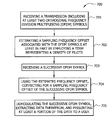
- a transmission is received that includes at least two OFDM symbols. In many instances, there may be a frequency offset between the transmitting and the sampling, such that SFO exists.
- an SFO is estimated for at least one of the OFDM symbols.
- Such estimation is performed at least in part by employing a term representing a density of pilots in the OFDM symbols.
- a term representing a density of pilots in the OFDM symbols For example, various embodiments use the term d k , described above.
- Step 702 can be performed using a variety of techniques, such as a scalar average technique, a vector sum technique, an early-late technique, and/or one or more other techniques.
- the SFO estimation in step 702 compensates, at least partly, for correlated errors in high pilot density areas.
- step 703 another OFDM symbol is received.
- step 704 the estimated SFO that was calculated in step 702 is used to correct for SFO in the later-received OFDM symbol. For example, a resampling operation can be performed to compensate for the SFO.
- step 705 the later-received OFDM symbol is demodulated and data is extracted from it. At least a portion of the data is presented to a user by, for example, a screen on a handheld device or personal computer and/or speakers on a handheld device or personal computer.
- While the above-described embodiment uses SFO estimates to correct for SFO in later-received symbols, various embodiments of the invention are not so limited. If the OFDM symbols that are used for the SFO estimation are buffered, then it is possible to apply the SFO estimate to perform SFO correction on those symbols themselves. The data is then extracted from the corrected symbols. Such an embodiment can be included in, e.g., a digital TV demodulator or other buffered application.
- Method 700 may further include computing the pilot density before or during step 702 .
- pilot density can be known quite quickly, even from as few as one observed OFDM symbol.
- the pilot pattern i.e., the set of the continual pilot indices
- the pilot pattern is fixed. If the pilot pattern is changed, the pilot density is re-computed. However, this will generally not occur in fixed pattern systems, such as those that use DVB-H.
- method 700 is shown as a series of discrete steps, it should be noted that various embodiments of the invention are not so limited. In fact, some embodiments may add, delete, modify, and/or rearrange steps. For instance, various embodiments repeat the steps of method 700 as OFDM symbols are received.
- FIG. 8 is an illustration of exemplary system 800 adapted according to one embodiment of the invention.
- System 800 is an exemplary system for transmitting and receiving data using OFDM techniques.
- System 800 can be adapted into a variety of specific applications, including applications for radio/television broadcast, data voice communication in a wireless telephone network, data communication using WIMAX or WIFI, and/or the like.
- Examples of applications of embodiments of the invention include, e.g., wireless Local Area Networks (LANs) and Metropolitan Area Networks (MANs), Digital Video Broadcasting-Television (DVB-T), Coded OFDM (COFDM), Multiband-OFDM (MB-OFDM) in Ultra Wideband (UWB) technology, 4G handheld technology, Third Generation Partnership Project's (3GPP) Long term Evolution (LTE), Integrated Services Digital Broadcasting (ISDB), and/or the like.
- 3GPP Third Generation Partnership Project's
- LTE Long term Evolution
- ISDB Integrated Services Digital Broadcasting
- principles of the invention can be applied to wired OFDM networks too, such as Asymmetric Digital Subscriber Line (ADSL) systems.
- ADSL Asymmetric Digital Subscriber Line
- System 800 includes transmitter 810 and receiver 820 .
- transmitter 810 in this embodiment, can be any OFDM transmitter now known or later developed.
- Transmitter 810 includes baseband modulator 811 and Digital to Analog Converter (DAC) 812 , each controlled by clock 814 , set at f Tx .
- Radio Frequency (RF) frontend 813 receives the data from DAC 812 and transmits the data using antenna 815 .
- DAC Digital to Analog Converter
- Receiver 820 receives the data from transmitter 810 via antenna 832 , RF frontend 821 , and Analog to Digital Converter (ADC) 822 .
- ADC Analog to Digital Converter
- the digital data from ADC 822 is received by baseband demodulator 823 .
- Demodulator 823 has a feedback loop for correcting for SFO.
- the feedback loop includes SFO corrector 824 , CP remover 825 , FFT module 826 , pilot extractor 831 , SFO estimator 830 , and Low Pass Filter 829 .
- SFO estimator 830 estimates SFO, as explained in detail above, and SFO corrector 824 uses the estimated SFO from estimator 830 to correct for SFO in subsequently received symbols. After FFT has been performed on the received data, the data is sent to equalizer 827 and to channel decoder 828 .
- SFO estimator 830 estimates the residual SFO error after SFO correct 824 provides correction to the signal.
- SFO estimator 830 can use the uncorrected signal directly.
- Embodiments of the present invention may provide one or more advantages over prior art systems. As mentioned above, some embodiments show lower error in SFO estimates versus prior art systems that use unmodified SFO estimation techniques (e.g., scalar average, vector sum, early-late). Further, many embodiments can be implemented with little added complexity/cost to current systems. For instance, many embodiments can work with current transmitters, thereby eliminating cost of replacing/upgrading transmitters. In many instances, applying the inventive technology is as simple as upgrading software/firmware or replacing a chip in an existing device.
- readable media can include any medium that can store information.
- FIG. 9 illustrates an example computer system 900 adapted according to embodiments of the present invention. That is, computer system 900 comprises an example system on which embodiments of the present invention may be implemented (such as system 100 of FIG. 1 ).
- Central processing unit (CPU) 901 is coupled to system bus 902 .
- CPU 901 may be any general purpose CPU. However, the present invention is not restricted by the architecture of CPU 901 as long as CPU 901 supports the inventive operations as described herein.
- CPU 901 executes the various logical instructions according to embodiments of the present invention. For example, one or more CPUs, such as CPU 901 , may execute machine-level instructions according to the exemplary operational flows described above in conjunction with FIG. 7 .
- Computer system 900 also preferably includes random access memory (RAM) 903 , which may be SRAM, DRAM, SDRAM, or the like.
- Computer system 900 preferably includes read-only memory (ROM) 904 which may be PROM, EPROM, EEPROM, or the like.
- RAM 903 and ROM 904 hold user and system data and programs, as is well known in the art.
- Computer system 900 also preferably includes input/output (I/O) adapter 905 , communications adapter 911 , user interface adapter 908 , and display adapter 909 .
- I/O adapter 905 , user interface adapter 908 , and/or communications adapter 911 may, in certain embodiments, enable a user to interact with computer system 900 in order to input information, such as Universal Resource Locators (URLs) that lead to network content.
- URLs Universal Resource Locators
- I/O adapter 905 preferably connects to storage device(s) 906 , such as one or more of hard drive, compact disc (CD) drive, floppy disk drive, tape drive, etc., to computer system 900 .
- storage device(s) 906 such as one or more of hard drive, compact disc (CD) drive, floppy disk drive, tape drive, etc.
- the storage devices may be utilized when RAM 903 is insufficient for the memory requirements associated with storing media data.
- Communications adapter 911 is preferably adapted to couple computer system 900 to network 912 (e.g., the Internet, a LAN, a cellular network, a wireless data network, e.g., WIFI, WIMAX, etc.).
- network 912 e.g., the Internet, a LAN, a cellular network, a wireless data network, e.g., WIFI, WIMAX, etc.
- communications adaptor 911 includes some or all of the components shown in system 800 of FIG. 8 .
- User interface adapter 908 couples user input devices, such as keyboard 913 , pointing device 907 , and microphone 914 and/or output devices, such as speaker(s) 915 to computer system 900 .
- Display adapter 909 is driven by CPU 901 to control the display on display device 910 to, for example, display received content.
- receivers may be any kind of processor-based device, such as a cell phone, a Personal Digital Assistant, a television tuner, a Set Top Box (STB) for a television, a wireless base LAN/MAN base station, and/or the like.
- various embodiments can implement the functionality described above in specialized hardware modules or as software modules that are executed on processor-based devices.
- embodiments of the present invention may be implemented on application specific integrated circuits (ASICs) or very large scale integrated (VLSI) circuits.
- ASICs application specific integrated circuits
- VLSI very large scale integrated circuits
Abstract
Description
J k,m =R k,m R* k,m−1 (2)
where an asterisk denotes the conjugate.
In a DVB-H system, k is one of the continual pilot sub-carrier indices. Equation 3 only provides the estimate given by one pilot sub-carrier. In most of the systems, more than one pilot sub-carrier will be available, and we are interested in a final estimate based on a plurality of εk,m given by different pilot sub-carriers k. Hence, techniques for combining the εk,m for different pilot sub-carriers k are provided below.
E└(εk,m−ε)(εk+d,m−ε)*┘, (10a)
where d is sub-carrier separation in terms of the number of sub-carriers. If the actual value of the SFO is zero, the correlation will be
Further, Equation 6 can be modified, as shown in Equation 13.
In Equations 12 and 13, dk is the weighting factor, which is indicative of pilot density. For example, dk can be defined as
where ak is the number of sub-carriers difference between the adjacent continual sub-carriers of the continual pilot index k, as shown in
In fact, other ways to calculate dk can be used that indicate sub-carrier separation or pilot density directly or indirectly.
Claims (20)
Priority Applications (1)
| Application Number | Priority Date | Filing Date | Title |
|---|---|---|---|
| US12/111,779 US8085860B2 (en) | 2008-04-29 | 2008-04-29 | Systems and methods for sampling frequency offset estimation |
Applications Claiming Priority (1)
| Application Number | Priority Date | Filing Date | Title |
|---|---|---|---|
| US12/111,779 US8085860B2 (en) | 2008-04-29 | 2008-04-29 | Systems and methods for sampling frequency offset estimation |
Publications (2)
| Publication Number | Publication Date |
|---|---|
| US20090268829A1 US20090268829A1 (en) | 2009-10-29 |
| US8085860B2 true US8085860B2 (en) | 2011-12-27 |
Family
ID=41215008
Family Applications (1)
| Application Number | Title | Priority Date | Filing Date |
|---|---|---|---|
| US12/111,779 Active 2030-10-18 US8085860B2 (en) | 2008-04-29 | 2008-04-29 | Systems and methods for sampling frequency offset estimation |
Country Status (1)
| Country | Link |
|---|---|
| US (1) | US8085860B2 (en) |
Cited By (1)
| Publication number | Priority date | Publication date | Assignee | Title |
|---|---|---|---|---|
| US10455534B2 (en) | 2013-01-31 | 2019-10-22 | Marvell World Trade Ltd. | Frequency offset compensation for WiFi ranging |
Families Citing this family (1)
| Publication number | Priority date | Publication date | Assignee | Title |
|---|---|---|---|---|
| AU2009217407C1 (en) | 2008-10-09 | 2015-07-23 | Sony Corporation | New frame and data pattern structure for multi-carrier systems |
Citations (19)
| Publication number | Priority date | Publication date | Assignee | Title |
|---|---|---|---|---|
| US5608764A (en) | 1993-11-12 | 1997-03-04 | Kabushiki Kaisha Toshiba | OFDM synchronization demodulation circuit |
| US20030072254A1 (en) * | 2001-10-17 | 2003-04-17 | Jianglei Ma | Scattered pilot pattern and channel estimation method for MIMO-OFDM systems |
| US20040109508A1 (en) * | 2002-12-09 | 2004-06-10 | Taehyun Jeon | Method and device for tracking carrier frequency offset and sampling frequency offset in orthogonal frequency division multiplexing wireless communication system |
| US20040131012A1 (en) | 2002-10-04 | 2004-07-08 | Apurva Mody | Methods and systems for sampling frequency offset detection, correction and control for MIMO OFDM systems |
| US20050084025A1 (en) * | 2003-10-20 | 2005-04-21 | Hung-Kun Chen | Timing offset compensation in orthogonal frequency division multiplexing systems |
| US20060034227A1 (en) * | 2004-08-02 | 2006-02-16 | Beceem Communications Inc. | Training information transmission method in a block transmission system |
| US20060039515A1 (en) | 2004-08-18 | 2006-02-23 | Lg Electronics Inc. | Method and apparatus for estimating SFO in digital receiver |
| US20060176802A1 (en) * | 2005-02-04 | 2006-08-10 | Samsung Electronics Co., Ltd. | Apparatus and method for compensating for frequency offset in wireless communication system |
| EP1694018A1 (en) * | 2005-02-18 | 2006-08-23 | Samsung Electronics Co., Ltd. | Method for compensating sampling frequency offset and OFDM signal receiving apparatus thereof |
| US7177374B2 (en) * | 2005-06-17 | 2007-02-13 | Broadcom Corporation | Apparatus and method for sampling frequency offset estimation and correction in a wireless communication system |
| US20070041312A1 (en) * | 2005-08-22 | 2007-02-22 | Samsung Electronics Co., Ltd. | Sampling frequency offset tracking method and OFDM system using the same |
| US20070053462A1 (en) * | 2005-09-06 | 2007-03-08 | Pirooz Ali D | Sampling frequency offset estimation and correction system and method for ultra wideband ofdm |
| US7224666B2 (en) * | 2002-05-13 | 2007-05-29 | Texas Instruments Incorporated | Estimating frequency offsets using pilot tones in an OFDM system |
| US20070286062A1 (en) * | 2006-06-07 | 2007-12-13 | Parul Gupta | Pilot based sampling frequency offset estimation and correction for an ofdm system |
| US20080232504A1 (en) * | 2005-08-23 | 2008-09-25 | Jianglei Ma | Methods and Systems For Ofdm Multiple Zone Partitioning |
| US20090213948A1 (en) * | 2005-08-23 | 2009-08-27 | Jianglei Ma | Adaptive two-dimensional channel interpolation |
| US20090268709A1 (en) * | 2008-04-23 | 2009-10-29 | Motorola, Inc. | Time and frequency correction for an access point in an ofdma communication system |
| US7711029B2 (en) * | 2005-12-02 | 2010-05-04 | Telefonaktiebolaget Lm Ericsson (Publ) | Hopping pilot pattern for telecommunications |
| US7738357B2 (en) * | 2005-06-17 | 2010-06-15 | Broadcom Corporation | Apparatus and method for carrier frequency offset estimation and correction in a wireless communication system |
-
2008
- 2008-04-29 US US12/111,779 patent/US8085860B2/en active Active
Patent Citations (20)
| Publication number | Priority date | Publication date | Assignee | Title |
|---|---|---|---|---|
| US5608764A (en) | 1993-11-12 | 1997-03-04 | Kabushiki Kaisha Toshiba | OFDM synchronization demodulation circuit |
| US20030072254A1 (en) * | 2001-10-17 | 2003-04-17 | Jianglei Ma | Scattered pilot pattern and channel estimation method for MIMO-OFDM systems |
| US7778337B2 (en) * | 2001-10-17 | 2010-08-17 | Nortel Networks Limited | Scattered pilot pattern and channel estimation method for MIMO-OFDM systems |
| US7224666B2 (en) * | 2002-05-13 | 2007-05-29 | Texas Instruments Incorporated | Estimating frequency offsets using pilot tones in an OFDM system |
| US20040131012A1 (en) | 2002-10-04 | 2004-07-08 | Apurva Mody | Methods and systems for sampling frequency offset detection, correction and control for MIMO OFDM systems |
| US20040109508A1 (en) * | 2002-12-09 | 2004-06-10 | Taehyun Jeon | Method and device for tracking carrier frequency offset and sampling frequency offset in orthogonal frequency division multiplexing wireless communication system |
| US20050084025A1 (en) * | 2003-10-20 | 2005-04-21 | Hung-Kun Chen | Timing offset compensation in orthogonal frequency division multiplexing systems |
| US20060034227A1 (en) * | 2004-08-02 | 2006-02-16 | Beceem Communications Inc. | Training information transmission method in a block transmission system |
| US20060039515A1 (en) | 2004-08-18 | 2006-02-23 | Lg Electronics Inc. | Method and apparatus for estimating SFO in digital receiver |
| US20060176802A1 (en) * | 2005-02-04 | 2006-08-10 | Samsung Electronics Co., Ltd. | Apparatus and method for compensating for frequency offset in wireless communication system |
| EP1694018A1 (en) * | 2005-02-18 | 2006-08-23 | Samsung Electronics Co., Ltd. | Method for compensating sampling frequency offset and OFDM signal receiving apparatus thereof |
| US7177374B2 (en) * | 2005-06-17 | 2007-02-13 | Broadcom Corporation | Apparatus and method for sampling frequency offset estimation and correction in a wireless communication system |
| US7738357B2 (en) * | 2005-06-17 | 2010-06-15 | Broadcom Corporation | Apparatus and method for carrier frequency offset estimation and correction in a wireless communication system |
| US20070041312A1 (en) * | 2005-08-22 | 2007-02-22 | Samsung Electronics Co., Ltd. | Sampling frequency offset tracking method and OFDM system using the same |
| US20080232504A1 (en) * | 2005-08-23 | 2008-09-25 | Jianglei Ma | Methods and Systems For Ofdm Multiple Zone Partitioning |
| US20090213948A1 (en) * | 2005-08-23 | 2009-08-27 | Jianglei Ma | Adaptive two-dimensional channel interpolation |
| US20070053462A1 (en) * | 2005-09-06 | 2007-03-08 | Pirooz Ali D | Sampling frequency offset estimation and correction system and method for ultra wideband ofdm |
| US7711029B2 (en) * | 2005-12-02 | 2010-05-04 | Telefonaktiebolaget Lm Ericsson (Publ) | Hopping pilot pattern for telecommunications |
| US20070286062A1 (en) * | 2006-06-07 | 2007-12-13 | Parul Gupta | Pilot based sampling frequency offset estimation and correction for an ofdm system |
| US20090268709A1 (en) * | 2008-04-23 | 2009-10-29 | Motorola, Inc. | Time and frequency correction for an access point in an ofdma communication system |
Non-Patent Citations (6)
| Title |
|---|
| Sands, N. P. et al, Pilotless Timing Recovery for Baseband Multicarrier Modulation, IEEE Journal on Selected Areas in Communications, Jun. 2002, pp. 1047-1054, vol. 20, No. 5, IEEE. |
| Sliskovic, M., Sampling Frequency Offset Estimation and Correction in OFDM Systems, IEEE, 2001, pp. 437-440. |
| Speth, M. et al., Optimum Receiver Design for OFDM-Based Broadband Transmission-Part II: A Case Study, IEEE Transactions on Communications, Apr. 2001, pp. 571-578, vol. 49, No. 4, IEEE. |
| Speth, M. et al., Optimum Receiver Design for OFDM-Based Broadband Transmission—Part II: A Case Study, IEEE Transactions on Communications, Apr. 2001, pp. 571-578, vol. 49, No. 4, IEEE. |
| Tsai, P. et al., Joint Weighted Least Squares Estimation of Frequency and Timing Offset for OFDM Systems over Fading Channels, IEEE, 2003, pp. 2543-2547. |
| Yang, B. et al., An Improved Combined Symbol and Sampling Clock Synchronization Method for OFDM Systems, IEEE, 1999, pp. 1153-1157. |
Cited By (1)
| Publication number | Priority date | Publication date | Assignee | Title |
|---|---|---|---|---|
| US10455534B2 (en) | 2013-01-31 | 2019-10-22 | Marvell World Trade Ltd. | Frequency offset compensation for WiFi ranging |
Also Published As
| Publication number | Publication date |
|---|---|
| US20090268829A1 (en) | 2009-10-29 |
Similar Documents
| Publication | Publication Date | Title |
|---|---|---|
| JP5524943B2 (en) | Receiver | |
| JP4125715B2 (en) | Method and apparatus for synchronizing initial frequency in OFDM system | |
| USRE44622E1 (en) | Coarse carrier frequency offset estimation for a receiver | |
| US8462613B2 (en) | Channel estimation for long term evolution (LTE) terminals | |
| US8116393B2 (en) | Method and apparatus for estimating channel state information | |
| US7778336B1 (en) | Timing and frequency synchronization of OFDM signals for changing channel conditions | |
| US8355468B2 (en) | Carrier frequency estimation method and apparatus in wireless communication system | |
| CN101257470B (en) | Method for using insertion pilot to inhibit phase noise in orthogonal frequency division multiplexing system | |
| US20110228884A1 (en) | Method and device for filtering channel estimation result in orthogonal frequency division multiplexing | |
| TWI455497B (en) | Method and associated apparatus applied to receiver of wireless network for frequency offset | |
| JP2006174472A (en) | Symbol timing inferring method, symbol timing inferring device and program | |
| US9054933B2 (en) | Orthogonal frequency division multiplex (OFDM) receiver with phase noise mitigation and reduced latency | |
| US20130279637A1 (en) | Method and System for A Reference Signal (RS) Timing Loop for OFDM Symbol Synchronization and Tracking | |
| US9674024B2 (en) | Method for transmitting a signal with a preamble and corresponding devices, signal with corresponding preamble for synchronization of a receiver | |
| US20100296438A1 (en) | UP-LINK SDMA RECEIVER FOR WiMAX | |
| US7529179B1 (en) | Joint maximum likelihood estimation of integer carrier frequency offset and channel in OFDM systems | |
| US20080273646A1 (en) | Sampling clock offset tracking and symbol re-timing | |
| US8107545B2 (en) | Method and system for phase tracking in wireless communication systems | |
| CN101534287A (en) | Method and device for correcting carrier frequency offset in mobile communication system | |
| US9210017B2 (en) | Reception device, reception method, and program | |
| US8085860B2 (en) | Systems and methods for sampling frequency offset estimation | |
| US8937989B1 (en) | Channel estimation using linear phase estimation | |
| US9369329B1 (en) | Low-complexity non-data-aided estimation of symbol time offset in OFDM systems | |
| US7693095B2 (en) | Apparatus and method for compensating for frequency / phase pulling bursts in received OFDM signals | |
| Assaf et al. | Sample Clock Offset Compensation in the fifth-generation new radio Downlink |
Legal Events
| Date | Code | Title | Description |
|---|---|---|---|
| AS | Assignment |
Owner name: HONG KONG APPLIED SCIENCE AND TECHNOLOGY RESEARCH Free format text: ASSIGNMENT OF ASSIGNORS INTEREST;ASSIGNORS:KWAN, MAN WAI;NG, MAN LUNG;SU, MICHAEL;AND OTHERS;REEL/FRAME:021213/0838;SIGNING DATES FROM 20080430 TO 20080529 Owner name: HONG KONG APPLIED SCIENCE AND TECHNOLOGY RESEARCH Free format text: ASSIGNMENT OF ASSIGNORS INTEREST;ASSIGNORS:KWAN, MAN WAI;NG, MAN LUNG;SU, MICHAEL;AND OTHERS;SIGNING DATES FROM 20080430 TO 20080529;REEL/FRAME:021213/0838 |
|
| STCF | Information on status: patent grant |
Free format text: PATENTED CASE |
|
| CC | Certificate of correction | ||
| FPAY | Fee payment |
Year of fee payment: 4 |
|
| MAFP | Maintenance fee payment |
Free format text: PAYMENT OF MAINTENANCE FEE, 8TH YEAR, LARGE ENTITY (ORIGINAL EVENT CODE: M1552); ENTITY STATUS OF PATENT OWNER: LARGE ENTITY Year of fee payment: 8 |
|
| MAFP | Maintenance fee payment |
Free format text: PAYMENT OF MAINTENANCE FEE, 12TH YEAR, LARGE ENTITY (ORIGINAL EVENT CODE: M1553); ENTITY STATUS OF PATENT OWNER: LARGE ENTITY Year of fee payment: 12 |