US8089354B2 - Wireless tracking system and method for backhaul of information - Google Patents
Wireless tracking system and method for backhaul of information Download PDFInfo
- Publication number
- US8089354B2 US8089354B2 US12/899,913 US89991310A US8089354B2 US 8089354 B2 US8089354 B2 US 8089354B2 US 89991310 A US89991310 A US 89991310A US 8089354 B2 US8089354 B2 US 8089354B2
- Authority
- US
- United States
- Prior art keywords
- mesh network
- healthcare device
- information
- sensors
- tags
- Prior art date
- Legal status (The legal status is an assumption and is not a legal conclusion. Google has not performed a legal analysis and makes no representation as to the accuracy of the status listed.)
- Active
Links
Images


Classifications
-
- H—ELECTRICITY
- H04—ELECTRIC COMMUNICATION TECHNIQUE
- H04Q—SELECTING
- H04Q9/00—Arrangements in telecontrol or telemetry systems for selectively calling a substation from a main station, in which substation desired apparatus is selected for applying a control signal thereto or for obtaining measured values therefrom
-
- A—HUMAN NECESSITIES
- A61—MEDICAL OR VETERINARY SCIENCE; HYGIENE
- A61B—DIAGNOSIS; SURGERY; IDENTIFICATION
- A61B5/00—Measuring for diagnostic purposes; Identification of persons
- A61B5/103—Detecting, measuring or recording devices for testing the shape, pattern, colour, size or movement of the body or parts thereof, for diagnostic purposes
- A61B5/11—Measuring movement of the entire body or parts thereof, e.g. head or hand tremor, mobility of a limb
- A61B5/1113—Local tracking of patients, e.g. in a hospital or private home
-
- G—PHYSICS
- G16—INFORMATION AND COMMUNICATION TECHNOLOGY [ICT] SPECIALLY ADAPTED FOR SPECIFIC APPLICATION FIELDS
- G16H—HEALTHCARE INFORMATICS, i.e. INFORMATION AND COMMUNICATION TECHNOLOGY [ICT] SPECIALLY ADAPTED FOR THE HANDLING OR PROCESSING OF MEDICAL OR HEALTHCARE DATA
- G16H40/00—ICT specially adapted for the management or administration of healthcare resources or facilities; ICT specially adapted for the management or operation of medical equipment or devices
- G16H40/20—ICT specially adapted for the management or administration of healthcare resources or facilities; ICT specially adapted for the management or operation of medical equipment or devices for the management or administration of healthcare resources or facilities, e.g. managing hospital staff or surgery rooms
-
- A—HUMAN NECESSITIES
- A61—MEDICAL OR VETERINARY SCIENCE; HYGIENE
- A61B—DIAGNOSIS; SURGERY; IDENTIFICATION
- A61B2560/00—Constructional details of operational features of apparatus; Accessories for medical measuring apparatus
- A61B2560/02—Operational features
- A61B2560/0266—Operational features for monitoring or limiting apparatus function
- A61B2560/0271—Operational features for monitoring or limiting apparatus function using a remote monitoring unit
-
- A—HUMAN NECESSITIES
- A61—MEDICAL OR VETERINARY SCIENCE; HYGIENE
- A61B—DIAGNOSIS; SURGERY; IDENTIFICATION
- A61B5/00—Measuring for diagnostic purposes; Identification of persons
- A61B5/0002—Remote monitoring of patients using telemetry, e.g. transmission of vital signals via a communication network
- A61B5/0015—Remote monitoring of patients using telemetry, e.g. transmission of vital signals via a communication network characterised by features of the telemetry system
- A61B5/002—Monitoring the patient using a local or closed circuit, e.g. in a room or building
-
- A—HUMAN NECESSITIES
- A61—MEDICAL OR VETERINARY SCIENCE; HYGIENE
- A61B—DIAGNOSIS; SURGERY; IDENTIFICATION
- A61B5/00—Measuring for diagnostic purposes; Identification of persons
- A61B5/68—Arrangements of detecting, measuring or recording means, e.g. sensors, in relation to patient
- A61B5/6887—Arrangements of detecting, measuring or recording means, e.g. sensors, in relation to patient mounted on external non-worn devices, e.g. non-medical devices
- A61B5/6889—Rooms
-
- H—ELECTRICITY
- H04—ELECTRIC COMMUNICATION TECHNIQUE
- H04Q—SELECTING
- H04Q2209/00—Arrangements in telecontrol or telemetry systems
- H04Q2209/20—Arrangements in telecontrol or telemetry systems using a distributed architecture
- H04Q2209/25—Arrangements in telecontrol or telemetry systems using a distributed architecture using a mesh network, e.g. a public urban network such as public lighting, bus stops or traffic lights
-
- H—ELECTRICITY
- H04—ELECTRIC COMMUNICATION TECHNIQUE
- H04Q—SELECTING
- H04Q2209/00—Arrangements in telecontrol or telemetry systems
- H04Q2209/40—Arrangements in telecontrol or telemetry systems using a wireless architecture
- H04Q2209/43—Arrangements in telecontrol or telemetry systems using a wireless architecture using wireless personal area networks [WPAN], e.g. 802.15, 802.15.1, 802.15.4, Bluetooth or ZigBee
Definitions
- the present invention is related to wireless tracking systems and methods. More specifically, the present invention relates to a system and method for backhauling information over a mesh network.
- Real-time knowledge of resources is becoming a necessary tool of many businesses. Real-time knowledge of the location, status and movement of crucial resources can allow a business to operate more efficiently and with fewer errors.
- many businesses employ hundreds if not thousands of resources in a single facility, and these resources need to be accounted for by a central system that is user friendly.
- a typical radio frequency identification system includes at least multiple tagged objects, each of which transmits a signal, multiple receivers for receiving the transmissions from the tagged objects, and a processing means for analyzing the transmissions to determine the locations of the tagged objects within a predetermined environment.
- U.S. Pat. No. 6,915,135 discloses a system for determining presence, identity and duration of presence in a given area (a table in a restaurant) of an object (tag attached to a waiter).
- U.S. Pat. No. 3,805,265 discloses a location system that uses line-of-sight radiant wave energy for signal transmission.
- Schwengler U.S. Pat. No. 7,050,819 is directed at the problem of adequate power for a mobile telephone for a two-way communication function or a regeneration function as a node of a mesh network.
- Zodnik U.S. Patent Publication Number 2004/0147232, discloses wall-mounted (RJ-11 or RJ-45) wireless transceivers configured to only track the location of a self-identified wireless communication device in order to communicate the location of the self-identified wireless communication device to an emergency service such as 911.
- the problem is inadequate resource visibility in a business. Businesses such as hospitals, need to locate resources (assets and people), know the status of the resources, and understand the usage history of the resources to enable business improvement.
- the present invention provides a solution to transmitting health information.
- the present invention utilizes a mesh network that acts to backhaul information obtained utilizing a healthcare device.
- One aspect of the present invention is a system for backhauling health information over a mesh network.
- the system includes a plurality of first tags, a mesh network, and an information engine.
- Each of the plurality of first tags represents a first object.
- the mesh network preferably includes a plurality of plug-in sensors located within the facility. At least one node in the mesh network operates as healthcare device.
- the information engine is in communication with the mesh network and determines a position location of the healthcare device and an operation of the healthcare device.
- the first object is fixed or mobile.
- the healthcare device is preferably at least one of a fluid pump, heart monitor, ventilation pump and electrocardiogram.
- the mesh network preferably routes information from the healthcare device to a predetermined destination.
- the mesh network preferably transmits data related to who accessed the healthcare device last.
- the mesh network preferably transmits data related to how much time is left before the device needs to be serviced.
- the mesh network preferably transmits data related to what type of chemicals are in the healthcare device.
- the mesh network preferably transmits data related to the status of the device.
- the mesh network preferably provides firmware upgrades to the healthcare device.
- the healthcare device preferably operates as a RTLS device using one of ultrasound, infrared and radiofrequency medium.
- the system includes a plurality of first tags and a mesh network.
- Each of the plurality of first tags represents a first object.
- the mesh network includes a plurality of sensors located within the facility.
- a plurality of nodes in the mesh network operate as RTLS devices using one of ultrasound, infrared, and a radiofrequency medium, wherein each of the plurality of end points transmit to at least one of a plurality of sensors in the mesh network.
- the mesh network routes RTLS information from each of the plurality of nodes to a predetermined destination.
- the mesh network preferably operates as an RTLS and a backhaul for information from each of the plurality of end points.
- the mesh network preferably operates as a secondary RTLS system and a backhaul for information from each of the plurality of end points.
- Each of the plurality of end points preferably operates as a healthcare device.
- the healthcare device is preferably at least one of a fluid pump, heart monitor, ventilation pump and electrocardiogram.
- the mesh network preferably routes information from the healthcare device to a predetermined destination.
- the mesh network preferably transmits data related to who accessed the healthcare device last.
- the mesh network preferably transmits data related to how much time is left before the device needs to be serviced.
- the mesh network preferably transmits data related to what type of chemicals are in the healthcare device.
- the mesh network preferably transmits data related to the status of the device.
- the mesh network preferably provides firmware upgrades to the healthcare device.
- the healthcare device preferably operates as a RTLS device using one of ultrasound, infrared
- a medium range wireless communication format is preferably selected from ZIGBEE communication format, Bluetooth communication format, Low-Power BlueTooth communication format, WiFi communication format, Low-Power WiFi communication format, Ultra Wide Band communication format, Ultrasound communication format or Infrared communication format.
- Real time location systems frequency abbreviated as RTLS, provide inherent characteristics which have both immediate tactical short-term benefits as well as long-term strategic implications for hospital operations.
- Real time location systems provide hospital administrators with actionable information regarding the location, status and movement of equipment and people.
- hospitals have access not only to the specific locations of equipment and people—but also advanced RTLS search capabilities allowing searching by specific location (floor, area, room) or unique asset identifier (department owner, type, manufacturer, model number, asset control number or EIN).
- FIG. 1 is schematic view of a system for analyzing an interaction between objects.
- FIG. 2 is a multi-floor view of a facility employing a system for analyzing an interaction between objects.
- FIG. 3 is a floor plan view of a single floor in a facility employing the system for analyzing an interaction between objects.
- FIG. 4 is a block diagram of a flow of information utilizing a system for analyzing an interaction between objects.
- FIG. 5 is a flow chart of a method for analyzing an interaction between objects.
- FIG. 6 is a flow chart of a method for analyzing an interaction between objects.
- FIG. 7 is a block diagram of a tag.
- FIG. 8 is a plan view of an identification badge containing a communication device.
- a system for tracking objects within a facility is generally designated 50 .
- the system 50 is capable of analyzing an interaction between objects, individuals 58 and/or devices 100 . and the system backhauls information over a mesh network to an information engine 65 for processing.
- the system 50 preferably includes a plurality of sensors 55 , a plurality of bridges 56 , a plurality of communication devices 59 , a plurality of tags 60 , and at least one information engine 65 .
- the sensors 55 form a mesh network for receiving signals from the communication devices 59 and tags 60 .
- One example of the components of the system 50 is disclosed in U.S. Pat. No.
- the system 50 is preferably employed at a facility 70 such as a business office, factory, home, hospital and/or government agency building.
- the system 50 is preferably utilized to backhaul information over the mesh network from various objects positioned throughout the facility 70 in order to analyze real time information pertaining to the object at an information engine 65 .
- the system 50 also tracks the location of objects in the facility 70 .
- the communication devices 59 and tags 60 preferably continuously transmit signals on a predetermined time cycle, and these signals are received by sensors 55 positioned throughout the facility 70 .
- the tags 60 and communication devices 59 transmit signals in a random, ad-hoc or dynamic manner, and these signals are received by the sensors 55 positioned throughout the facility 70 .
- the sensors 55 transmit the data from the communication devices 59 and tags 60 to a bridge 56 for transmission to the information engine 65 . If a sensor 55 is unable to transmit to a bridge 56 , the sensor 55 may transmit to another sensor 55 in a mesh network for eventual transmission to a bridge 56 . In a preferred embodiment, a transmission may be sent from a transmission distance of six sensors 55 from a bridge 56 . Alternatively, a transmission is sent from a transmission distance ranging from ten to twenty sensors 55 from a bridge 56 .
- the information engine 65 preferably continuously receives transmissions from the mesh network formed by the sensors 55 via the bridges 56 concerning the operation of objects 100 bearing the communication device 59 and/or bearing a tag 60 within the facility 70 .
- the information engine 65 processes the transmissions from the sensors 55 and calculates a real-time position for each of the objects and data concerning the object 100 within the facility 70 .
- the real-time location information for each of the objects is preferably displayed on a graphical user interface (“GUI”).
- GUI graphical user interface
- a floor plan image may also be used with a graphical user interface of a computer, personal digital assistant, or the like so that an individual of the facility 70 is able to quickly locate objects 100 within the facility 70 , know the real-time status of the object (is the object in operation, in need of maintenance, or similar information).
- the system 50 utilizes sensors 55 to monitor and identify the real-time status and position of objects 100 bearing or integrated with communication devices 59 .
- the sensors 55 a - f preferably wirelessly communicate with each other (shown as double arrow lines) and with an information engine 65 through a wired connection 66 via at least one bridge 56 , such as disclosed in the above-mentioned U.S. Pat. No. 7,324,824 for a Plug-In Network Appliance.
- the communication devices 59 and tags 60 transmit wireless signals 57 which are received by the sensors 55 a - e , which then transmit signals to bridges 56 for eventual transmission to the information engine 65 .
- the information engine 65 is preferably located on-site at the facility 70 . However, the system 50 may also include an off-site information engine 65 , not shown.
- each communication device 59 and tag 60 preferably transmits a radio frequency signal of approximately 2.48 GigaHertz (“GHz”).
- the communication format is preferably IEEE Standard 802.15.4.
- each communication device 59 and tag 60 transmits an infrared signal or an ultrasound signal.
- Each device preferably contains a low-power, medium-range (1 foot to 30 feet) wireless communication system.
- Such wireless communication systems include ZIGBEE, BLUETOOTH, Low-Power BLUETOOTH, WiFi or Low-Power WiFi, Ultra Wide Band (“UWB”), Ultrasound and Infrared communication systems.
- the wireless communication system is used to exchange device specific information after the low-power short-range system has indicated that an interaction has occurred.
- the wireless communication system can also be used independent of the low-power short-range system for other wireless communication applications such as location and tracking, sense and control, building automation, smart energy, telecom applications, consumer building automation, remote control applications, home health care, personal fitness, personal wellness, and many other applications.
- the tags 60 may be constructed with an asset theft protection system such as disclosed in Baranowski et al., U.S. Pat. No. 7,443,297 for a Wireless Tracking System And Method With Optical Tag Removal Detection, which is hereby incorporated by reference in its entirety.
- the tags 60 and communication devices 59 may be designed to avoid multipath errors such as disclosed in Nierenberg et al., U.S. Pat. No.
- the facility 70 is depicted as a hospital.
- the facility 70 has multiple floors 75 a - c .
- Each floor 75 a , 75 b and 75 c has multiple rooms 90 a - i , with each room 90 accessible through a door 85 .
- Positioned throughout the facility 70 are sensors 55 a - o for obtaining readings from communication devices 59 and tags 60 attached to people or devices.
- a bridge 56 is also shown for receiving transmissions from the sensors 55 for backhauling the information over the mesh network to the information engine 65 . For example, as shown in FIG.
- the system 50 determines that individuals 58 a , 58 b and 58 c are located in a surgery room and are using device 100 c , which is a surgical kit.
- the information engine 65 analyzes the interaction by monitoring the duration of the interaction, the devices 100 utilized, the location of the interaction (surgery), the previous location of the individuals 58 (possibly a surgical prep room) and additional factors. Also shown in FIG. 2 , information pertaining to a fluid pump 100 b is sent from the fluid pump 100 b , acting as a node in the mesh network, to the sensor 55 for backhauling over the mesh network to the information engine 65 .
- the backhauled information provides a current, real time status of the fluid pump, what types of chemicals are contained within it, the levels of the chemicals, the temperature, and other valuable information.
- a hospital can obtain valuable information about its equipment, machines, and the like, without having to use a human resource to obtain the information since the information is backhauled over the mesh network to at least one information engine 65 for analysis and display on a GUI if required.
- the system 50 determines that individuals 58 a , 58 b and 58 c are located in a patient's room and are using device with an attached tag 60 c , which is a patient monitoring device.
- individual 58 a is a patient
- individual 58 b is a physician
- individual 58 c is a nurse.
- the information engine 65 analyzes the interaction by monitoring the duration of the interaction, the devices 100 utilized, the location of the interaction (patient's room), the previous location of the individuals 58 and additional factors. The information engine 65 uses this data to generate billing information for the patient.
- FIG. 4 illustrates a preferred architecture of the system 50 .
- the information providers are set forth on one side of the network and the operations is set forth on the other side of the network.
- the illustrated architecture of the system 50 is not meant to limit any physical relationship between information providers and operations.
- an individual 58 could be tracked while accessing information from a device 100 such as a computer 66 in operations.
- the information providers include individuals 58 that wear communication devices 59 , an electrocardiogram having a communication device 60 , sterilizable equipment 100 b bearing sterilizable tags 60 , and the like.
- a description of sterilizable tags 60 is found in Caliri et al., U.S. patent application Ser. No.
- a bridge 56 acts as an intermediary between the backhaul information and the information engine.
- the bridge 56 communicates information to the information engine 65 which analyzes the information to determine an interaction between objects for access through an enterprise local area network for display on computers 66 or other graphical user interface devices.
- a method 1000 for backhauling information over a mesh network is illustrated in FIG. 5 .
- a communication device associated with an object in this case a ventilation pump, operates as a node in the mesh network and a healthcare device.
- the ventilation pump also operates as a RTLS device.
- a wireless signal is transmitted from the ventilation pump using a medium power communication protocol such as ultrasound, infrared and radiofrequency.
- the first wireless signal is received at least one of a plurality of sensors positioned within a facility.
- the signal is forwarded over the mesh network using a communication protocol such as ZIGBEE.
- the signal is received at an information engine.
- the information engine analyzes the backhauled information on the signal for a multiple of factors.
- the multiple factors include a status of the device, a position location of an action, a duration of the action, a previous location of the device prior to the action, and information for other objects or persons within a predetermined distance of the location of the action.
- the backhauled information is communicated to a graphical user interface.
- FIG. 6 Another method 2000 for backhauling information over a mesh network is illustrated in FIG. 6 .
- a healthcare device operates as a RTLS device and as a node in a mesh network.
- the healthcare device is a heart rate monitor.
- a wireless signal is transmitted from the healthcare device using a medium power communication protocol such as ultrasound, infrared and radiofrequency.
- the first wireless signal is received at least one of a plurality of sensors positioned within a facility.
- the signal is forwarded to an information engine.
- the information engine determines that a firmware upgrade is needed at the healthcare device.
- the information engine through the mesh network transmits the firmware upgrade to the healthcare device.
- the healthcare device receives the firmware and performs an upgrade of its firmware.
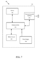
- a tag 60 utilized with a device 100 is illustrated in FIG. 7 .
- the tag 60 preferably includes a microcontroller 101 , a transceiver 103 , a power supply 104 and a sensor 106 .
- the tag 60 includes a motion sensor 105 .
- the transmissions are transmitted through transceiver 103 .
- a power supply 104 provides power to the tag 60 . All of the components are preferably contained within a housing 107 .
- a communication device 59 preferably has the same components and structure of the tag 60 illustrated in FIG. 7 .
- FIG. 8 is a block diagram of a system for determining a real-time location of an object.
- Sensors receive the messages from the broadcasting tags through attached different antennas, calculate the signal strength, and decide which signal strength to use.
- the signal strength information is routed to the server for location processing.
- Bridge/appliance/server devices received signal strength information from the high definitions sensors and make location decisions.
- the tag sends broadcast messages preferably using ZIGBEE based wireless transmissions.
- the sensors receive the ZIGBEE based wireless transmissions preferably through two spatially and angularly diverse antennas.
- Software on each sensor preferably identifies and matches the sending tag and received signal strength readings.
- Software on each sensor preferably makes local decisions on the final signal strength value for the transponder.
- Each sensor preferably sends the signal strength information to the appliance through a wireless ZIGBEE based wireless transmission network.
- the tags and sensors communicate to the bridges preferably through a ZIGBEE based wireless transmission network.
- the location of the tags is preferably calculated by using the paired signal strength between tags and the sensors that hear the tag.
- Time slicing is also utilized in determining a real-time location of the object within an indoor facility by making time slots available in each antenna.
- a patient wears, or has attached, a patient tag 60 a and a plurality of medical devices bearing or integrated with tags 60 b .
- Such healthcare devices may include blood pressure monitors, dialysis devices, respiration aids, oxygen tanks, wheelchairs, and the like, and all may act as nodes in a mesh network.
- the plurality of network monitors preferably utilize ZIGBEE networking standards and technology, such as disclosed at zigbee.org, which pertinent parts are hereby incorporated by reference.
Abstract
Description
Claims (19)
Priority Applications (3)
| Application Number | Priority Date | Filing Date | Title |
|---|---|---|---|
| US12/899,913 US8089354B2 (en) | 2009-10-08 | 2010-10-07 | Wireless tracking system and method for backhaul of information |
| US12/982,832 US8040238B2 (en) | 2009-10-08 | 2010-12-30 | Wireless tracking system and method for backhaul of information |
| US13/338,346 US20120133489A1 (en) | 2009-10-08 | 2011-12-28 | Wireless Tracking System And Method For Backhaul Of Information |
Applications Claiming Priority (2)
| Application Number | Priority Date | Filing Date | Title |
|---|---|---|---|
| US24962909P | 2009-10-08 | 2009-10-08 | |
| US12/899,913 US8089354B2 (en) | 2009-10-08 | 2010-10-07 | Wireless tracking system and method for backhaul of information |
Related Child Applications (2)
| Application Number | Title | Priority Date | Filing Date |
|---|---|---|---|
| US12/982,832 Continuation US8040238B2 (en) | 2009-10-08 | 2010-12-30 | Wireless tracking system and method for backhaul of information |
| US13/338,346 Continuation US20120133489A1 (en) | 2009-10-08 | 2011-12-28 | Wireless Tracking System And Method For Backhaul Of Information |
Publications (2)
| Publication Number | Publication Date |
|---|---|
| US20110084806A1 US20110084806A1 (en) | 2011-04-14 |
| US8089354B2 true US8089354B2 (en) | 2012-01-03 |
Family
ID=43854401
Family Applications (3)
| Application Number | Title | Priority Date | Filing Date |
|---|---|---|---|
| US12/899,913 Active US8089354B2 (en) | 2009-10-08 | 2010-10-07 | Wireless tracking system and method for backhaul of information |
| US12/982,832 Active US8040238B2 (en) | 2009-10-08 | 2010-12-30 | Wireless tracking system and method for backhaul of information |
| US13/338,346 Abandoned US20120133489A1 (en) | 2009-10-08 | 2011-12-28 | Wireless Tracking System And Method For Backhaul Of Information |
Family Applications After (2)
| Application Number | Title | Priority Date | Filing Date |
|---|---|---|---|
| US12/982,832 Active US8040238B2 (en) | 2009-10-08 | 2010-12-30 | Wireless tracking system and method for backhaul of information |
| US13/338,346 Abandoned US20120133489A1 (en) | 2009-10-08 | 2011-12-28 | Wireless Tracking System And Method For Backhaul Of Information |
Country Status (1)
| Country | Link |
|---|---|
| US (3) | US8089354B2 (en) |
Cited By (19)
| Publication number | Priority date | Publication date | Assignee | Title |
|---|---|---|---|---|
| US20110148624A1 (en) * | 2009-12-22 | 2011-06-23 | Mindray Ds Usa, Inc. | Systems and methods for determining a location of a medical device |
| US8857716B1 (en) | 2011-02-21 | 2014-10-14 | Proxense, Llc | Implementation of a proximity-based system for object tracking and automatic application initialization |
| US9524632B2 (en) | 2014-03-10 | 2016-12-20 | Gojo Industries, Inc. | Hygiene tracking compliance |
| US10061899B2 (en) | 2008-07-09 | 2018-08-28 | Baxter International Inc. | Home therapy machine |
| US10304304B1 (en) | 2015-03-02 | 2019-05-28 | Enovate Medical, Llc | Asset management using an asset tag device |
| US10698989B2 (en) | 2004-12-20 | 2020-06-30 | Proxense, Llc | Biometric personal data key (PDK) authentication |
| US10764044B1 (en) | 2006-05-05 | 2020-09-01 | Proxense, Llc | Personal digital key initialization and registration for secure transactions |
| US10769939B2 (en) | 2007-11-09 | 2020-09-08 | Proxense, Llc | Proximity-sensor supporting multiple application services |
| US10909229B2 (en) | 2013-05-10 | 2021-02-02 | Proxense, Llc | Secure element as a digital pocket |
| US10943471B1 (en) | 2006-11-13 | 2021-03-09 | Proxense, Llc | Biometric authentication using proximity and secure information on a user device |
| US10971251B1 (en) | 2008-02-14 | 2021-04-06 | Proxense, Llc | Proximity-based healthcare management system with automatic access to private information |
| US11080378B1 (en) | 2007-12-06 | 2021-08-03 | Proxense, Llc | Hybrid device having a personal digital key and receiver-decoder circuit and methods of use |
| US11086979B1 (en) | 2007-12-19 | 2021-08-10 | Proxense, Llc | Security system and method for controlling access to computing resources |
| US11095640B1 (en) | 2010-03-15 | 2021-08-17 | Proxense, Llc | Proximity-based system for automatic application or data access and item tracking |
| US11120449B2 (en) | 2008-04-08 | 2021-09-14 | Proxense, Llc | Automated service-based order processing |
| US11206664B2 (en) | 2006-01-06 | 2021-12-21 | Proxense, Llc | Wireless network synchronization of cells and client devices on a network |
| US11258791B2 (en) | 2004-03-08 | 2022-02-22 | Proxense, Llc | Linked account system using personal digital key (PDK-LAS) |
| US11546325B2 (en) | 2010-07-15 | 2023-01-03 | Proxense, Llc | Proximity-based system for object tracking |
| US11553481B2 (en) | 2006-01-06 | 2023-01-10 | Proxense, Llc | Wireless network synchronization of cells and client devices on a network |
Families Citing this family (43)
| Publication number | Priority date | Publication date | Assignee | Title |
|---|---|---|---|---|
| US8029454B2 (en) * | 2003-11-05 | 2011-10-04 | Baxter International Inc. | High convection home hemodialysis/hemofiltration and sorbent system |
| US8269604B2 (en) * | 2009-01-14 | 2012-09-18 | Vendwatch Telematics, Llc | Remotely monitoring field assets |
| WO2015074007A1 (en) * | 2013-11-15 | 2015-05-21 | Leaf Healthcare, Inc. | Prevention and treatment of bed exits, falls, and other conditions |
| US10729357B2 (en) | 2010-04-22 | 2020-08-04 | Leaf Healthcare, Inc. | Systems and methods for generating and/or adjusting a repositioning schedule for a person |
| US11278237B2 (en) | 2010-04-22 | 2022-03-22 | Leaf Healthcare, Inc. | Devices, systems, and methods for preventing, detecting, and treating pressure-induced ischemia, pressure ulcers, and other conditions |
| US10631732B2 (en) | 2009-03-24 | 2020-04-28 | Leaf Healthcare, Inc. | Systems and methods for displaying sensor-based user orientation information |
| NZ749991A (en) | 2010-01-05 | 2020-01-31 | Isolynx Llc | Systems and methods for analyzing event data |
| US11369309B2 (en) | 2010-04-22 | 2022-06-28 | Leaf Healthcare, Inc. | Systems and methods for managing a position management protocol based on detected inclination angle of a person |
| US9655546B2 (en) | 2010-04-22 | 2017-05-23 | Leaf Healthcare, Inc. | Pressure Ulcer Detection Methods, Devices and Techniques |
| US11051751B2 (en) | 2010-04-22 | 2021-07-06 | Leaf Healthcare, Inc. | Calibrated systems, devices and methods for preventing, detecting, and treating pressure-induced ischemia, pressure ulcers, and other conditions |
| US10140837B2 (en) | 2010-04-22 | 2018-11-27 | Leaf Healthcare, Inc. | Systems, devices and methods for the prevention and treatment of pressure ulcers, bed exits, falls, and other conditions |
| US11272860B2 (en) | 2010-04-22 | 2022-03-15 | Leaf Healthcare, Inc. | Sensor device with a selectively activatable display |
| US10758162B2 (en) | 2010-04-22 | 2020-09-01 | Leaf Healthcare, Inc. | Systems, devices and methods for analyzing a person status based at least on a detected orientation of the person |
| US10588565B2 (en) | 2010-04-22 | 2020-03-17 | Leaf Healthcare, Inc. | Calibrated systems, devices and methods for preventing, detecting, and treating pressure-induced ischemia, pressure ulcers, and other conditions |
| US8578001B2 (en) | 2010-06-25 | 2013-11-05 | Digi International Inc. | Smart energy gateway with integrated plug |
| US8378848B2 (en) | 2010-06-25 | 2013-02-19 | Digi International Inc. | Virtual smart energy meter with integrated plug |
| US8583040B2 (en) * | 2010-10-01 | 2013-11-12 | Digi International Inc. | Devices, systems, and methods for configuring a wireless device |
| CA2949476C (en) | 2010-11-19 | 2020-06-16 | Isolynx, Llc | Associative object tracking systems and methods |
| US8600374B1 (en) * | 2011-02-11 | 2013-12-03 | Awarepoint Corporation | Sterilizable wireless tracking and communication device and method for manufacturing |
| US9525976B2 (en) * | 2012-05-10 | 2016-12-20 | Honeywell International Inc. | BIM-aware location based application |
| GB201214976D0 (en) * | 2012-08-22 | 2012-10-03 | Connect In Ltd | Monitoring system |
| US20140111322A1 (en) * | 2012-10-23 | 2014-04-24 | Chad Steelberg | System and Method for Capturing and Transmitting Real Time Sports Performance Data |
| US9081076B2 (en) | 2012-11-12 | 2015-07-14 | Isolynx, Llc | System and method for object tracking anti-jitter filtering |
| US20140210617A1 (en) * | 2013-01-28 | 2014-07-31 | Timekeeping Systems, Inc. | System to facilitate well-being checks |
| US11423464B2 (en) | 2013-06-06 | 2022-08-23 | Zebra Technologies Corporation | Method, apparatus, and computer program product for enhancement of fan experience based on location data |
| US20140364973A1 (en) | 2013-06-06 | 2014-12-11 | Zih Corp. | Method, apparatus, and computer program product for monitoring health, fitness, operation, or performance of individuals |
| US10609762B2 (en) | 2013-06-06 | 2020-03-31 | Zebra Technologies Corporation | Method, apparatus, and computer program product improving backhaul of sensor and other data to real time location system network |
| US10437658B2 (en) | 2013-06-06 | 2019-10-08 | Zebra Technologies Corporation | Method, apparatus, and computer program product for collecting and displaying sporting event data based on real time data for proximity and movement of objects |
| US9715005B2 (en) | 2013-06-06 | 2017-07-25 | Zih Corp. | Method, apparatus, and computer program product improving real time location systems with multiple location technologies |
| US9699278B2 (en) | 2013-06-06 | 2017-07-04 | Zih Corp. | Modular location tag for a real time location system network |
| US9517417B2 (en) | 2013-06-06 | 2016-12-13 | Zih Corp. | Method, apparatus, and computer program product for performance analytics determining participant statistical data and game status data |
| US9661455B2 (en) | 2014-06-05 | 2017-05-23 | Zih Corp. | Method, apparatus, and computer program product for real time location system referencing in physically and radio frequency challenged environments |
| US9668164B2 (en) | 2014-06-05 | 2017-05-30 | Zih Corp. | Receiver processor for bandwidth management of a multiple receiver real-time location system (RTLS) |
| GB2541834B (en) | 2014-06-05 | 2020-12-23 | Zebra Tech Corp | Receiver processor for adaptive windowing and high-resolution TOA determination in a multiple receiver target location system |
| US9626616B2 (en) | 2014-06-05 | 2017-04-18 | Zih Corp. | Low-profile real-time location system tag |
| US10261169B2 (en) | 2014-06-05 | 2019-04-16 | Zebra Technologies Corporation | Method for iterative target location in a multiple receiver target location system |
| WO2015187991A1 (en) | 2014-06-05 | 2015-12-10 | Zih Corp. | Systems, apparatus and methods for variable rate ultra-wideband communications |
| US20150375083A1 (en) | 2014-06-05 | 2015-12-31 | Zih Corp. | Method, Apparatus, And Computer Program Product For Enhancement Of Event Visualizations Based On Location Data |
| US9759803B2 (en) | 2014-06-06 | 2017-09-12 | Zih Corp. | Method, apparatus, and computer program product for employing a spatial association model in a real time location system |
| EP3152585B1 (en) | 2014-06-06 | 2022-04-27 | Zebra Technologies Corporation | Method, apparatus, and computer program product improving real time location systems with multiple location technologies |
| US10117959B2 (en) | 2016-06-07 | 2018-11-06 | General Electric Company | Smart sterilization tracker tag |
| EP3920559A1 (en) | 2020-06-05 | 2021-12-08 | Chipolo d.o.o. | Out of range tracking device detection |
| DE102020129712A1 (en) | 2020-11-11 | 2022-05-12 | Ziehl-Abegg Se | Method for locating and maintaining a system module to be found |
Citations (15)
| Publication number | Priority date | Publication date | Assignee | Title |
|---|---|---|---|---|
| US5812865A (en) * | 1993-12-03 | 1998-09-22 | Xerox Corporation | Specifying and establishing communication data paths between particular media devices in multiple media device computing systems based on context of a user or users |
| US7164667B2 (en) | 2002-06-28 | 2007-01-16 | Belair Networks Inc. | Integrated wireless distribution and mesh backhaul networks |
| US20080012767A1 (en) * | 2003-10-22 | 2008-01-17 | Awarepoint Corporation | Wireless Tracking System And Method With Multipath Error Mitigation |
| US7336182B1 (en) * | 2007-10-19 | 2008-02-26 | Awarepoint Corporation | Wireless tracking system and method with optical tag removal detection |
| US7366120B2 (en) | 2004-10-18 | 2008-04-29 | Nortel Networks, Ltd | Method and apparatus for improving quality of service over meshed bachaul facilities in a wireless network |
| US7453858B2 (en) | 2002-04-26 | 2008-11-18 | Samsung Electronics Co., Ltd. | Apparatus and method for adapting WI-FI access point to wireless backhaul link of a wireless network |
| US7466985B1 (en) | 2005-09-30 | 2008-12-16 | Nortel Networks Limited | Network element for implementing scheduled high-power PTP and low-power PTMP transmissions |
| US20090067333A1 (en) | 2007-09-07 | 2009-03-12 | Wichorus Inc. | Apparatus and method for controlling traffic flow in backhaul link in wireless communication network |
| US20090069642A1 (en) * | 2007-09-11 | 2009-03-12 | Aid Networks, Llc | Wearable Wireless Electronic Patient Data Communications and Physiological Monitoring Device |
| US7573382B2 (en) * | 2007-04-02 | 2009-08-11 | General Electric Company | System and method to manage movement of assets |
| US7580729B2 (en) | 2004-06-10 | 2009-08-25 | Interdigital Technology Corporation | Method and system for utilizing smart antennas in establishing a backhaul network |
| US20090213730A1 (en) | 2008-02-21 | 2009-08-27 | Jianlin Zeng | Backhaul failover method and system for a wireless network |
| US20090224868A1 (en) * | 2008-03-04 | 2009-09-10 | Wen-Shiang Liu | Personal Protective Equipment and Managing System Thereof |
| US7660559B2 (en) | 2003-01-10 | 2010-02-09 | Belair Networks Inc. | Automatic antenna selection for mesh backhaul network nodes |
| US7688762B2 (en) | 2007-03-21 | 2010-03-30 | Cisco Technology, Inc. | Mesh backhaul network planning |
-
2010
- 2010-10-07 US US12/899,913 patent/US8089354B2/en active Active
- 2010-12-30 US US12/982,832 patent/US8040238B2/en active Active
-
2011
- 2011-12-28 US US13/338,346 patent/US20120133489A1/en not_active Abandoned
Patent Citations (15)
| Publication number | Priority date | Publication date | Assignee | Title |
|---|---|---|---|---|
| US5812865A (en) * | 1993-12-03 | 1998-09-22 | Xerox Corporation | Specifying and establishing communication data paths between particular media devices in multiple media device computing systems based on context of a user or users |
| US7453858B2 (en) | 2002-04-26 | 2008-11-18 | Samsung Electronics Co., Ltd. | Apparatus and method for adapting WI-FI access point to wireless backhaul link of a wireless network |
| US7164667B2 (en) | 2002-06-28 | 2007-01-16 | Belair Networks Inc. | Integrated wireless distribution and mesh backhaul networks |
| US7660559B2 (en) | 2003-01-10 | 2010-02-09 | Belair Networks Inc. | Automatic antenna selection for mesh backhaul network nodes |
| US20080012767A1 (en) * | 2003-10-22 | 2008-01-17 | Awarepoint Corporation | Wireless Tracking System And Method With Multipath Error Mitigation |
| US7580729B2 (en) | 2004-06-10 | 2009-08-25 | Interdigital Technology Corporation | Method and system for utilizing smart antennas in establishing a backhaul network |
| US7366120B2 (en) | 2004-10-18 | 2008-04-29 | Nortel Networks, Ltd | Method and apparatus for improving quality of service over meshed bachaul facilities in a wireless network |
| US7466985B1 (en) | 2005-09-30 | 2008-12-16 | Nortel Networks Limited | Network element for implementing scheduled high-power PTP and low-power PTMP transmissions |
| US7688762B2 (en) | 2007-03-21 | 2010-03-30 | Cisco Technology, Inc. | Mesh backhaul network planning |
| US7573382B2 (en) * | 2007-04-02 | 2009-08-11 | General Electric Company | System and method to manage movement of assets |
| US20090067333A1 (en) | 2007-09-07 | 2009-03-12 | Wichorus Inc. | Apparatus and method for controlling traffic flow in backhaul link in wireless communication network |
| US20090069642A1 (en) * | 2007-09-11 | 2009-03-12 | Aid Networks, Llc | Wearable Wireless Electronic Patient Data Communications and Physiological Monitoring Device |
| US7336182B1 (en) * | 2007-10-19 | 2008-02-26 | Awarepoint Corporation | Wireless tracking system and method with optical tag removal detection |
| US20090213730A1 (en) | 2008-02-21 | 2009-08-27 | Jianlin Zeng | Backhaul failover method and system for a wireless network |
| US20090224868A1 (en) * | 2008-03-04 | 2009-09-10 | Wen-Shiang Liu | Personal Protective Equipment and Managing System Thereof |
Cited By (43)
| Publication number | Priority date | Publication date | Assignee | Title |
|---|---|---|---|---|
| US11258791B2 (en) | 2004-03-08 | 2022-02-22 | Proxense, Llc | Linked account system using personal digital key (PDK-LAS) |
| US11922395B2 (en) | 2004-03-08 | 2024-03-05 | Proxense, Llc | Linked account system using personal digital key (PDK-LAS) |
| US10698989B2 (en) | 2004-12-20 | 2020-06-30 | Proxense, Llc | Biometric personal data key (PDK) authentication |
| US11553481B2 (en) | 2006-01-06 | 2023-01-10 | Proxense, Llc | Wireless network synchronization of cells and client devices on a network |
| US11219022B2 (en) | 2006-01-06 | 2022-01-04 | Proxense, Llc | Wireless network synchronization of cells and client devices on a network with dynamic adjustment |
| US11800502B2 (en) | 2006-01-06 | 2023-10-24 | Proxense, LL | Wireless network synchronization of cells and client devices on a network |
| US11206664B2 (en) | 2006-01-06 | 2021-12-21 | Proxense, Llc | Wireless network synchronization of cells and client devices on a network |
| US11212797B2 (en) | 2006-01-06 | 2021-12-28 | Proxense, Llc | Wireless network synchronization of cells and client devices on a network with masking |
| US11157909B2 (en) | 2006-05-05 | 2021-10-26 | Proxense, Llc | Two-level authentication for secure transactions |
| US11551222B2 (en) | 2006-05-05 | 2023-01-10 | Proxense, Llc | Single step transaction authentication using proximity and biometric input |
| US11182792B2 (en) | 2006-05-05 | 2021-11-23 | Proxense, Llc | Personal digital key initialization and registration for secure transactions |
| US10764044B1 (en) | 2006-05-05 | 2020-09-01 | Proxense, Llc | Personal digital key initialization and registration for secure transactions |
| US10943471B1 (en) | 2006-11-13 | 2021-03-09 | Proxense, Llc | Biometric authentication using proximity and secure information on a user device |
| US10769939B2 (en) | 2007-11-09 | 2020-09-08 | Proxense, Llc | Proximity-sensor supporting multiple application services |
| US11562644B2 (en) | 2007-11-09 | 2023-01-24 | Proxense, Llc | Proximity-sensor supporting multiple application services |
| US11080378B1 (en) | 2007-12-06 | 2021-08-03 | Proxense, Llc | Hybrid device having a personal digital key and receiver-decoder circuit and methods of use |
| US11086979B1 (en) | 2007-12-19 | 2021-08-10 | Proxense, Llc | Security system and method for controlling access to computing resources |
| US10971251B1 (en) | 2008-02-14 | 2021-04-06 | Proxense, Llc | Proximity-based healthcare management system with automatic access to private information |
| US11727355B2 (en) | 2008-02-14 | 2023-08-15 | Proxense, Llc | Proximity-based healthcare management system with automatic access to private information |
| US11120449B2 (en) | 2008-04-08 | 2021-09-14 | Proxense, Llc | Automated service-based order processing |
| US10224117B2 (en) | 2008-07-09 | 2019-03-05 | Baxter International Inc. | Home therapy machine allowing patient device program selection |
| US10095840B2 (en) | 2008-07-09 | 2018-10-09 | Baxter International Inc. | System and method for performing renal therapy at a home or dwelling of a patient |
| US10068061B2 (en) | 2008-07-09 | 2018-09-04 | Baxter International Inc. | Home therapy entry, modification, and reporting system |
| US10061899B2 (en) | 2008-07-09 | 2018-08-28 | Baxter International Inc. | Home therapy machine |
| US20110148624A1 (en) * | 2009-12-22 | 2011-06-23 | Mindray Ds Usa, Inc. | Systems and methods for determining a location of a medical device |
| US8334768B2 (en) * | 2009-12-22 | 2012-12-18 | Mindray Ds Usa, Inc. | Systems and methods for determining a location of a medical device |
| US11095640B1 (en) | 2010-03-15 | 2021-08-17 | Proxense, Llc | Proximity-based system for automatic application or data access and item tracking |
| US11546325B2 (en) | 2010-07-15 | 2023-01-03 | Proxense, Llc | Proximity-based system for object tracking |
| US10217339B1 (en) * | 2011-02-21 | 2019-02-26 | Proxense, Llc | Proximity-based system for object tracking and automatic application initialization |
| US11669701B2 (en) | 2011-02-21 | 2023-06-06 | Proxense, Llc | Implementation of a proximity-based system for object tracking and automatic application initialization |
| US11113482B1 (en) | 2011-02-21 | 2021-09-07 | Proxense, Llc | Implementation of a proximity-based system for object tracking and automatic application initialization |
| US8857716B1 (en) | 2011-02-21 | 2014-10-14 | Proxense, Llc | Implementation of a proximity-based system for object tracking and automatic application initialization |
| US9265450B1 (en) * | 2011-02-21 | 2016-02-23 | Proxense, Llc | Proximity-based system for object tracking and automatic application initialization |
| US11132882B1 (en) * | 2011-02-21 | 2021-09-28 | Proxense, Llc | Proximity-based system for object tracking and automatic application initialization |
| US9904816B1 (en) | 2011-02-21 | 2018-02-27 | Proxense, Llc | Implementation of a proximity-based system for object tracking and automatic application initialization |
| US10229294B1 (en) | 2011-02-21 | 2019-03-12 | Proxense, Llc | Implementation of a proximity-based system for object tracking and automatic application initialization |
| US10089443B2 (en) | 2012-05-15 | 2018-10-02 | Baxter International Inc. | Home medical device systems and methods for therapy prescription and tracking, servicing and inventory |
| US10909229B2 (en) | 2013-05-10 | 2021-02-02 | Proxense, Llc | Secure element as a digital pocket |
| US11914695B2 (en) | 2013-05-10 | 2024-02-27 | Proxense, Llc | Secure element as a digital pocket |
| US9524632B2 (en) | 2014-03-10 | 2016-12-20 | Gojo Industries, Inc. | Hygiene tracking compliance |
| US10304304B1 (en) | 2015-03-02 | 2019-05-28 | Enovate Medical, Llc | Asset management using an asset tag device |
| US10360421B1 (en) | 2015-03-02 | 2019-07-23 | Enovate Medical, Llc | Asset management using an asset tag device |
| US10949633B1 (en) | 2015-03-02 | 2021-03-16 | Enovate Medical, Llc | Asset management using an asset tag device |
Also Published As
| Publication number | Publication date |
|---|---|
| US20120133489A1 (en) | 2012-05-31 |
| US20110084809A1 (en) | 2011-04-14 |
| US8040238B2 (en) | 2011-10-18 |
| US20110084806A1 (en) | 2011-04-14 |
Similar Documents
| Publication | Publication Date | Title |
|---|---|---|
| US8089354B2 (en) | Wireless tracking system and method for backhaul of information | |
| US20130257614A1 (en) | Wireless Tracking System And Method For Backhaul Of Information | |
| US8285564B2 (en) | Wireless tracking system and method for analyzing an interaction between objects | |
| US8867993B1 (en) | Wireless tracking system and method utilizing near-field communication devices | |
| US8368540B2 (en) | Wireless tracking system and method utilizing near-field communication devices | |
| US20140227974A1 (en) | Wireless Tracking System And Method Utilizing Near-Field Communication Devices | |
| Adame et al. | CUIDATS: An RFID–WSN hybrid monitoring system for smart health care environments | |
| US20140195257A1 (en) | Method And System For Workflow Modification | |
| US9147334B2 (en) | System and method for monitoring hospital workflow compliance with a hand hygiene network | |
| US20140195256A1 (en) | Workflow Context Aware Location Tracking System And Method | |
| Yan et al. | Wireless sensor network based E-health system-implementation and experimental results | |
| US6954148B2 (en) | Method and system for selectively monitoring activities in a tracking environment | |
| US8903416B1 (en) | Wireless tracking system and method utilizing near-field communication devices | |
| US8727216B2 (en) | Portable memory module with wireless emitter to facilitate the provision of location-dependent services | |
| CN101516256A (en) | IP based monitoring and alarming | |
| US11862330B2 (en) | Proximity based systems for contact tracing | |
| Varshney | Wireless networks for enhanced monitoring of patients | |
| WO2011044337A2 (en) | Wireless tracking system and method for backhaul of information | |
| WO2014163996A1 (en) | Method and system for workflow modification | |
| WO2014163948A1 (en) | Workflow context aware location tracking system and method | |
| Dong et al. | Cognitive radio mobile ad hoc networks in healthcare | |
| KR102387199B1 (en) | Healthcare system and its communication method | |
| Bahrami et al. | Convergence of IoT and WBSN for Smart Control of Patients Health | |
| US11170324B2 (en) | Intelligent routing of patients using distributed input devices | |
| Sharma et al. | An Overview of Wireless Network in Medical Applications |
Legal Events
| Date | Code | Title | Description |
|---|---|---|---|
| AS | Assignment |
Owner name: PATIENT CARE TECHOLOGY SYSTEMS, LLC, NORTH CAROLIN Free format text: SECURITY AGREEMENT;ASSIGNOR:AWAREPOINT CORPORATION;REEL/FRAME:026159/0597 Effective date: 20110415 |
|
| AS | Assignment |
Owner name: WMX, LLC, NORTH CAROLINA Free format text: CHANGE OF NAME;ASSIGNOR:PATIENT CARE TECHNOLOGY SYSTEMS, LLC;REEL/FRAME:026254/0186 Effective date: 20110420 |
|
| AS | Assignment |
Owner name: AWAREPOINT CORPORATION, CALIFORNIA Free format text: ASSIGNMENT OF ASSIGNORS INTEREST;ASSIGNOR:PERKINS, MATTHEW R.;REEL/FRAME:026697/0514 Effective date: 20110802 |
|
| STCF | Information on status: patent grant |
Free format text: PATENTED CASE |
|
| AS | Assignment |
Owner name: AWAREPOINT CORPORATION, CALIFORNIA Free format text: RELEASE BY SECURED PARTY;ASSIGNOR:WMX, LLC;REEL/FRAME:030440/0546 Effective date: 20130426 Owner name: SILICON VALLEY BANK, CALIFORNIA Free format text: SECURITY AGREEMENT;ASSIGNOR:AWAREPOINT CORPORATION;REEL/FRAME:030452/0277 Effective date: 20130429 |
|
| AS | Assignment |
Owner name: ARES CAPITAL CORPORATION, ILLINOIS Free format text: SECURITY INTEREST;ASSIGNOR:AWAREPOINT CORPORATION;REEL/FRAME:033695/0249 Effective date: 20140905 |
|
| AS | Assignment |
Owner name: AWAREPOINT CORPORATION, CALIFORNIA Free format text: RELEASE BY SECURED PARTY;ASSIGNOR:SILICON VALLEY BANK;REEL/FRAME:034038/0917 Effective date: 20141022 |
|
| FPAY | Fee payment |
Year of fee payment: 4 |
|
| AS | Assignment |
Owner name: ARES CAPITAL CORPORATION, NEW YORK Free format text: CORRECTIVE ASSIGNMENT TO CORRECT THE ADDRESS OF ASSIGNEE PREVIOUSLY RECORDED ON REEL 033695 FRAME 249. ASSIGNOR(S) HEREBY CONFIRMS THE SECURITY INTEREST;ASSIGNOR:AWAREPOINT CORPORATION;REEL/FRAME:037108/0606 Effective date: 20140905 |
|
| AS | Assignment |
Owner name: CLINICAL PATENTS, LLC, PENNSYLVANIA Free format text: ASSIGNMENT OF ASSIGNORS INTEREST;ASSIGNOR:AWAREPOINT CORPORATION;REEL/FRAME:046521/0391 Effective date: 20180620 |
|
| FEPP | Fee payment procedure |
Free format text: ENTITY STATUS SET TO UNDISCOUNTED (ORIGINAL EVENT CODE: BIG.); ENTITY STATUS OF PATENT OWNER: LARGE ENTITY |
|
| MAFP | Maintenance fee payment |
Free format text: PAYMENT OF MAINTENANCE FEE, 8TH YEAR, LARGE ENTITY (ORIGINAL EVENT CODE: M1552); ENTITY STATUS OF PATENT OWNER: LARGE ENTITY Year of fee payment: 8 |
|
| AS | Assignment |
Owner name: CENTRAK, INC., PENNSYLVANIA Free format text: ASSIGNMENT OF ASSIGNORS INTEREST;ASSIGNOR:CLINICAL PATENTS, LLC;REEL/FRAME:055234/0721 Effective date: 20210205 |
|
| MAFP | Maintenance fee payment |
Free format text: PAYMENT OF MAINTENANCE FEE, 12TH YEAR, LARGE ENTITY (ORIGINAL EVENT CODE: M1553); ENTITY STATUS OF PATENT OWNER: LARGE ENTITY Year of fee payment: 12 |