US8090585B2 - Audio decoding device - Google Patents
Audio decoding device Download PDFInfo
- Publication number
- US8090585B2 US8090585B2 US11/822,907 US82290707A US8090585B2 US 8090585 B2 US8090585 B2 US 8090585B2 US 82290707 A US82290707 A US 82290707A US 8090585 B2 US8090585 B2 US 8090585B2
- Authority
- US
- United States
- Prior art keywords
- data processing
- audio
- data
- section
- audio data
- Prior art date
- Legal status (The legal status is an assumption and is not a legal conclusion. Google has not performed a legal analysis and makes no representation as to the accuracy of the status listed.)
- Active, expires
Links
- 238000011084 recovery Methods 0.000 claims description 54
- 230000007704 transition Effects 0.000 claims description 20
- 238000000034 method Methods 0.000 claims description 12
- 230000004807 localization Effects 0.000 description 20
- 238000010586 diagram Methods 0.000 description 17
- 238000001514 detection method Methods 0.000 description 1
- 230000000694 effects Effects 0.000 description 1
Images


Classifications
-
- H—ELECTRICITY
- H04—ELECTRIC COMMUNICATION TECHNIQUE
- H04S—STEREOPHONIC SYSTEMS
- H04S3/00—Systems employing more than two channels, e.g. quadraphonic
- H04S3/008—Systems employing more than two channels, e.g. quadraphonic in which the audio signals are in digital form, i.e. employing more than two discrete digital channels
-
- G—PHYSICS
- G10—MUSICAL INSTRUMENTS; ACOUSTICS
- G10L—SPEECH ANALYSIS OR SYNTHESIS; SPEECH RECOGNITION; SPEECH OR VOICE PROCESSING; SPEECH OR AUDIO CODING OR DECODING
- G10L19/00—Speech or audio signals analysis-synthesis techniques for redundancy reduction, e.g. in vocoders; Coding or decoding of speech or audio signals, using source filter models or psychoacoustic analysis
- G10L19/008—Multichannel audio signal coding or decoding using interchannel correlation to reduce redundancy, e.g. joint-stereo, intensity-coding or matrixing
-
- H—ELECTRICITY
- H04—ELECTRIC COMMUNICATION TECHNIQUE
- H04N—PICTORIAL COMMUNICATION, e.g. TELEVISION
- H04N21/00—Selective content distribution, e.g. interactive television or video on demand [VOD]
- H04N21/40—Client devices specifically adapted for the reception of or interaction with content, e.g. set-top-box [STB]; Operations thereof
- H04N21/43—Processing of content or additional data, e.g. demultiplexing additional data from a digital video stream; Elementary client operations, e.g. monitoring of home network or synchronising decoder's clock; Client middleware
- H04N21/439—Processing of audio elementary streams
-
- H—ELECTRICITY
- H04—ELECTRIC COMMUNICATION TECHNIQUE
- H04S—STEREOPHONIC SYSTEMS
- H04S2420/00—Techniques used stereophonic systems covered by H04S but not provided for in its groups
- H04S2420/03—Application of parametric coding in stereophonic audio systems
Definitions
- the present invention relates to an audio decoding device for decoding stream data containing encoded audio data.
- Some digital television broadcasting services (e.g., in Europe or the like) use stream data containing encrypted main audio (stereo), and in addition, stream data containing encrypted auxiliary audio used for explanation of a broadcast content.
- stream data containing encrypted main audio stereo
- stream data containing encrypted auxiliary audio used for explanation of a broadcast content.
- a device for receiving the digital television broadcast combines main audio data (stereo) and auxiliary audio data obtained by decoding these stream data before outputting them.
- main audio data stereo
- auxiliary audio data obtained by decoding these stream data before outputting them.
- the main audio data and the auxiliary audio data are simply combined, the loudness becomes larger than necessary, which is not comfortable for listening. Therefore, it is necessary to reduce the loudness of the main audio data to some extent before combination so as to obtain an appropriate loudness after combination. Also, if the sound localization of the auxiliary audio data can be controlled, it is convenient for listeners.
- the stream data of the auxiliary audio data contains parameters for processing the main audio data and the auxiliary audio data to adjust the relationship in loudness between the main audio data and the auxiliary audio data, and controlling the sound localization of auxiliary audio.
- An audio decoding device for decoding these stream data uses the parameters to adjust the loudness and control the sound localization (e.g., Digital TV Group, “Digital Terrestrial Television Requirements for Interoperability Issue 4.0” (Section 4.5 Audio description), Jan. 11, 2005).
- the parameter may be altered into an inappropriate value, depending on the reception conditions.
- the loudness cannot be appropriately adjusted, for example.
- An object of the present invention is to provide an audio decoding device which can appropriately perform data processing (e.g., loudness adjustment, etc.) even if a parameter for the data processing which is contained in stream data has an appropriate value.
- an embodiment of the present invention is an audio decoding device for decoding stream data containing encoded audio data.
- the audio decoding device receives first stream data containing encoded data obtained by encoding first audio data, and second stream data containing encoded data obtained by encoding second audio data and a data processing parameter for processing the first audio data and the second audio data.
- the device comprises an audio decoding section for decoding the first stream data and the second stream data to generate the first and second audio data and the data processing parameter, an external setting section in which a parameter corresponding to the data processing parameter is set, and an audio data processing section for processing the first and second audio data.
- the audio data processing section processes at least one of the first and second audio data using the parameter set in the external setting section when the data processing parameter contained in the second stream data is inappropriate, and using the data processing parameter generated by the audio decoding section when the data processing parameter contained in the second stream data is appropriate.
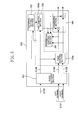
- FIG. 1 is a block diagram showing a configuration of an audio decoding device 100 according to Embodiment 1 of the present invention.
- FIG. 2 is a diagram showing an exemplary content described in an external setting section 102 .
- FIG. 3 is a block diagram showing a configuration of an audio decoding device according to Variation 1 of Embodiment 1 of the present invention.
- FIG. 4 is a block diagram showing a configuration of an audio decoding device according to Variation 2 of Embodiment 1 of the present invention.
- FIG. 5 is a block diagram showing a configuration of an audio decoding device 200 according to Embodiment 2 of the present invention.
- FIG. 6 is a block diagram showing a configuration of an audio decoding device 300 according to Embodiment 3 of the present invention.
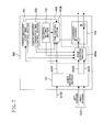
- FIG. 7 is a block diagram showing a configuration of an audio decoding device 400 according to Embodiment 4 of the present invention.
- FIG. 8 is a block diagram showing a configuration of an audio decoding device according to Variation 1 of Embodiment 4 of the present invention.
- FIG. 9 is a block diagram showing a configuration of an audio decoding device according to Variation 2 of Embodiment 4 of the present invention.
- Embodiments and variations hereinafter described are for illustrating audio decoding devices for decoding and outputting audio information in digital television broadcasting.
- Each audio decoding device receives two kinds of audio stream data (hereinafter simply abbreviated as stream data), decodes each piece of stream data, combines the pieces of decoded audio data, and outputs the result.
- stream data two kinds of audio stream data
- One of the two kinds of stream data is stream data (referred to as first stream data S 101 ) containing main audio data of a digital television broadcast.
- the main audio data is input through two channels (a left channel and a right channel (stereo)).
- the other stream data is stream data (referred to as second stream data S 102 ) containing auxiliary audio data of a digital television broadcast, which is used for the purpose of explanation of the broadcast content, for example.
- the loudness of the combined data becomes larger than necessary.
- the loudness of the main audio data may be previously reduced so as to obtain an appropriate loudness of the combined audio. Also, it is convenient for listeners to be able to control the sound localization of the auxiliary audio data.
- stream information for processing the main audio data and the auxiliary audio data is contained in the second stream data S 102 .
- the stream information contains two parameters (referred to as data processing parameters).
- a fade value is a parameter which indicates how much the loudness of the main audio data is reduced before the main audio data and the auxiliary audio data are combined.
- the other data processing parameter is a parameter referred to as “pan”.
- a pan value is a parameter which is used to control the sound localization of the auxiliary audio.
- first stream data S 101 and the second stream data S 102 is “main program data” and “audio description data”, which are used in digital broadcasting standards which are defined in “Digital Terrestrial Television Requirements for Interoperability Issue 4.0” by “Digital TV Group”, which is an industry association in the UK.
- FIG. 1 is a block diagram showing a configuration of an audio decoding device 100 according to Embodiment 1 of the present invention.
- the audio decoding device 100 comprises an audio decoding section 101 , an external setting section 102 , an audio data processing section 103 , and a combining section 104 .
- the audio decoding section 101 outputs first decoded data S 103 obtained by decoding first stream data S 101 and second decoded data S 104 obtained by decoding second stream data S 102 .
- the first stream data S 101 contains two channels (a left channel and a right channel) of main audio data (stereo), and therefore, the first decoded data S 103 are also 2-channel stereo data.
- the second decoded data S 104 obtained by decoding the second stream data S 102 contains one channel of auxiliary audio data, and in addition, a fade value and a pan value.
- the external setting section 102 can set a value corresponding to a fade value and a value corresponding to a pan value (these values are referred to as external setting information).
- the external setting information is set in the external setting section 102 by a user (e.g., a person who designs a television broadcast receiver or the like using this device, a person who views and listens to a broadcast using a television broadcast receiver or the like in which this device is incorporated).
- a fade value selection flag which indicates which of the fade value contained in the second decoded data S 104 and the fade value set in the external setting section 102 is used for the loudness adjustment
- a pan value selection flag which indicates which of the pan value contained in the second decoded data S 104 and the pan value set in the external setting section 102 is used for the sound localization control.
- these flags may be rewritten with a predetermined value (e.g., 0x1 when appropriate and 0x0 when inappropriate), depending on the result of detection by an error detecting section (not shown) of whether or not the fade value in the second stream data S 102 or the like is inappropriate (error).
- FIG. 2 shows an exemplary content described in the external setting section 102 .
- the audio data processing section 103 comprises a fade control section 103 a and a pan control section 103 b , and processes the main audio data and the auxiliary audio data.
- processes performed by the audio data processing section 103 in this embodiment include a control of a relationship in loudness between the main audio data and the auxiliary audio data, and a control of sound localization of the auxiliary audio data.
- the fade control section 103 a selects any one of the fade value contained in the second decoded data S 104 and the fade value contained in the external setting section 102 , depending on the value of the fade value selection flag, and uses the selected value to adjust the loudness of the main audio data (specifically, the loudness is reduced by a predetermined amount (hereinafter referred to as a fade control)). Specifically, if the fade value in the received second stream data S 102 or the like is inappropriate, the fade value in the external setting section 102 is used for the fade control, and if otherwise, the fade value contained in the second decoded data S 104 is used for the fade control.
- the pan control section 103 b selects any one of the pan value contained in the second decoded data S 104 and the pan value contained in the external setting section 102 , depending on the value of the pan value selection flag, and uses the selected value to control the sound localization of the auxiliary audio data (hereinafter referred to as a pan control). Specifically, if the pan value in the received second stream data S 102 or the like is inappropriate, the pan value in the external setting section 102 is used for the pan control, and if otherwise, the pan value contained in the second decoded data S 104 is used for the pan control. Note that the output of the pan control section 103 b is 2-channel stereo data. The loudness adjustment or the sound localization control using the fade value or the pan value in the external setting section 102 is referred to as error recovery.
- the combining section 104 combines an output of the fade control section 103 a and an output of the pan control section 103 b and outputs the result.
- the value of a flag corresponding to the inappropriate parameter in the external setting section 102 is set to be a value indicating that the parameter is inappropriate.
- the audio decoding section 101 decodes the input first stream data S 101 and second stream data S 102 and outputs the first decoded data S 103 and the second decoded data S 104 , respectively.
- the fade control section 103 a When the fade value selection flag indicates that the fade value in the second stream data S 102 is inappropriate, the fade control section 103 a reads out a fade value from the external setting section 102 , and adjusts the loudness of the main audio data based on the fade value thus read out. When the fade value selection flag indicates that the fade value in the second stream data S 102 is appropriate, the fade control section 103 a adjusts the loudness of the first decoded data S 103 based on the fade value in the second decoded data S 104 .
- the pan control section 103 b reads out a pan value from the external setting section 102 , and controls the sound localization of the auxiliary audio data based on the pan value thus read out.
- the pan control section 103 b controls the sound localization of the auxiliary audio data based on the pan value in the second decoded data S 104 .
- the value set in the external setting section 102 is used to perform the loudness adjustment and the sound localization control, thereby guaranteeing an appropriate audio output.
- FIG. 3 is a block diagram showing a configuration of an audio decoding device according to Variation 1 of Embodiment 1 of the present invention.
- the pan control section 103 b is adapted to invariably reference the pan value in the second decoded data S 104 during the sound localization control.
- the pan control section 103 b may be configured as in this variation, in a device for an area where monaural broadcasts are dominant. Note that, even in this variation, when the fade value in the second stream data S 102 is inappropriate, a fade control is performed using a value set in the external setting section 102 .
- FIG. 4 is a block diagram showing a configuration of an audio decoding device according to Variation 2 of Embodiment 1 of the present invention.
- the fade control section 103 a is adapted to invariably reference the fade value in the second decoded data S 104 during the loudness control. Note that, also in this variation, when the pan value in the second stream data S 102 is inappropriate, a value set in the external setting section 102 is used to perform the pan control.
- FIG. 5 is a block diagram showing a configuration of an audio decoding device 200 according to Embodiment 2 of the present invention. As shown in FIG. 5 , the audio decoding device 200 is obtained by adding a parameter control section 201 to the audio decoding device 100 .
- the parameter control section 201 sets a fade value and a pan value in the external setting section 102 , depending on an output of the fade control section 103 a and an output of the pan control section 103 b .
- the parameter control section 201 determines and sets a fade value in the external setting section 102 so that the amplitude of an output of the fade control section 103 a when the loudness adjustment is performed using the fade value in the external setting section 102 is not significantly different from that when the loudness adjustment is performed using an appropriate fade value in the second decoded data S 104 .
- the parameter control section 201 determines and set a pan value in the external setting section 102 so that the locations of sounds when the sound localization is controlled using the pan value in the external setting section 102 are not significantly different from those when the sound localization is controlled using an appropriate pan value in the second decoded data S 104 .
- parameter control section 201 may set a fade value and a pan value in the external setting section 102 , depending on the amplitude of an output of the combining section 104 .
- the parameter control section 201 may be adapted to set only a fade value, depending on an output of the fade control section 103 a , and a pan value may be set by the user.
- the parameter control section 201 may be adapted to set only a pan value, depending on an output of the pan control section 103 b , and a fade value may be set by the user.
- FIG. 6 is a block diagram showing a configuration of an audio decoding device 300 according to Embodiment 3 of the present invention. As shown in FIG. 6 , the audio decoding device 300 is obtained by replacing the combining section 104 with a combining section 301 and adding a combination selection section 302 to the audio decoding device 100 .
- the combining section 301 selectively outputs any one of a signal obtained by combining an output of the fade control section 103 a and an output of the pan control section 103 b , and an output signal of the fade control section 103 a , depending on an input control signal (referred to as a combination control signal).
- the combination selection section 302 receives an external instruction (e.g., an instruction from a listener), and outputs the combination control signal to the combining section 301 in response to the external instruction.
- an external instruction e.g., an instruction from a listener
- the audio decoding device 300 it is possible to determine whether or not to listen to auxiliary audio.
- FIG. 7 is a block diagram showing a configuration of an audio decoding device 400 according to Embodiment 4 of the present invention. As shown in FIG. 7 , the audio decoding device 400 is obtained by providing an audio data processing section 403 instead of the audio data processing section 103 and adding an error recovery start time control section 401 and an error recovery transition time control section 402 to the audio decoding device 100 .
- the audio data processing section 403 comprises a fade control section 403 a and a pan control section 403 b , and processes main audio data and auxiliary audio data.
- the fade control section 403 a is adapted from the fade control section 103 a so that timing of starting error recovery and a time required to transition from a current loudness to a loudness corresponding to a newly selected fade value (referred to as an error recovery transition time) can be changed, depending on an input predetermined control signal.
- the pan control section 403 b is adapted from the pan control section 103 b so that timing of starting error recovery and a time required to transition from current sound localization to sound localization corresponding to a newly selected pan value (also referred to as an error recovery transition time) can be set, depending on an input predetermined control signal.
- the error recovery start time control section 401 determines that start of error recovery is required, and instructs the fade control section 403 a or the pan control section 403 b which requires start of error recovery, to start error recovery.
- the error recovery transition time control section 402 indicates the error recovery transition times with respect to the fade control section 403 a and the pan control section 403 b.
- the error recovery start time control section 401 instructs the fade control section 403 a or the pan control section 403 b which requires start of error recovery, to start error recovery.
- the error recovery transition time control section 402 indicates the error recovery transition times with respect to the fade control section 403 a and the pan control section 403 b.
- the fade control section 403 a and the pan control section 403 b control the loudness level or the sound localization in a stepwise manner from current states to states corresponding to a new parameter in the given error recovery transition time.
- the control of the loudness or the sound localization is performed in a stepwise manner. Therefore, for example, it is possible to avoid a sudden change in the loudness or the like due to a sudden error.
- the error recovery start time control section 401 may count the number of errors occurring per unit time, and may instruct start of error recovery when the result exceeds a predetermined number. In some applications, the error recovery start time control section 401 may instruct start of error recovery as soon as an error is detected.
- the error recovery start time control section 401 is adapted to be able to execute each of these error recovery instructing methods (the instruction of error recovery based on the error continuation time, the instruction of error recovery based on the number of errors occurring per unit time, etc.), and change the error recovery instructing methods, depending on, for example, an environment where the audio decoding device 400 is used. Thereby, error recovery can be executed with the least sense of discomfort.
- FIG. 8 is a block diagram showing a configuration of an audio decoding device according to Variation 1 of Embodiment 4 of the present invention.
- the error recovery timing and the error recovery transition time are controlled only in the fade control.
- the error recovery start timing of the pan control is controlled based on a flag set in the external setting section 102 as in the audio decoding device 100 or the like, and a time required for error recovery (error recovery transition time) is set to be a default value.
- FIG. 9 is a block diagram showing a configuration of an audio decoding device according to Variation 2 of Embodiment 4 of the present invention.
- the error recovery timing and the error recovery transition time are controlled only in the pan control.
- the error recovery start timing of the fade control is controlled based on a flag set in the external setting section 102 as in the audio decoding device 100 or the like, and a time required for error recovery (error recovery transition time) is set to be a default value.
- the audio decoding device of the present invention has the effect that data processing, such as loudness adjustment or the like, can be appropriately performed even when a data processing parameter contained in stream data has an inappropriate value, and is useful as, for example, an audio decoding device which decodes stream data containing encoded audio data.
Abstract
Description
Claims (6)
Applications Claiming Priority (2)
| Application Number | Priority Date | Filing Date | Title |
|---|---|---|---|
| JP2006275276A JP4257862B2 (en) | 2006-10-06 | 2006-10-06 | Speech decoder |
| JP2006-275276 | 2006-10-06 |
Publications (2)
| Publication Number | Publication Date |
|---|---|
| US20080086312A1 US20080086312A1 (en) | 2008-04-10 |
| US8090585B2 true US8090585B2 (en) | 2012-01-03 |
Family
ID=38542036
Family Applications (1)
| Application Number | Title | Priority Date | Filing Date |
|---|---|---|---|
| US11/822,907 Active 2030-10-06 US8090585B2 (en) | 2006-10-06 | 2007-07-11 | Audio decoding device |
Country Status (3)
| Country | Link |
|---|---|
| US (1) | US8090585B2 (en) |
| EP (1) | EP1909538B1 (en) |
| JP (1) | JP4257862B2 (en) |
Families Citing this family (6)
| Publication number | Priority date | Publication date | Assignee | Title |
|---|---|---|---|---|
| US8644526B2 (en) | 2008-06-27 | 2014-02-04 | Panasonic Corporation | Audio signal decoding device and balance adjustment method for audio signal decoding device |
| WO2010082471A1 (en) * | 2009-01-13 | 2010-07-22 | パナソニック株式会社 | Audio signal decoding device and method of balance adjustment |
| US9043444B2 (en) * | 2011-05-25 | 2015-05-26 | Google Inc. | Using an audio stream to identify metadata associated with a currently playing television program |
| BR112013033835B1 (en) | 2011-07-01 | 2021-09-08 | Dolby Laboratories Licensing Corporation | METHOD, APPARATUS AND NON- TRANSITIONAL ENVIRONMENT FOR IMPROVED AUDIO AUTHORSHIP AND RENDING IN 3D |
| US10091581B2 (en) * | 2015-07-30 | 2018-10-02 | Roku, Inc. | Audio preferences for media content players |
| WO2024004651A1 (en) * | 2022-06-29 | 2024-01-04 | ソニーグループ株式会社 | Audio playback device, audio playback method, and audio playback program |
Citations (9)
| Publication number | Priority date | Publication date | Assignee | Title |
|---|---|---|---|---|
| JPH05110528A (en) | 1991-10-18 | 1993-04-30 | Nec Ic Microcomput Syst Ltd | On-vehicle audio device and its sound field control method |
| JPH10209977A (en) | 1997-01-24 | 1998-08-07 | Mitsubishi Electric Corp | Received data expansion device |
| US5852800A (en) * | 1995-10-20 | 1998-12-22 | Liquid Audio, Inc. | Method and apparatus for user controlled modulation and mixing of digitally stored compressed data |
| WO2001058064A1 (en) | 2000-02-04 | 2001-08-09 | Hearing Enhancement Company Llc | Use of voice-to-remaining audio (vra) in consumer applications |
| US20030039366A1 (en) * | 2001-05-07 | 2003-02-27 | Eid Bradley F. | Sound processing system using spatial imaging techniques |
| US20030125933A1 (en) * | 2000-03-02 | 2003-07-03 | Saunders William R. | Method and apparatus for accommodating primary content audio and secondary content remaining audio capability in the digital audio production process |
| US20050058304A1 (en) | 2001-05-04 | 2005-03-17 | Frank Baumgarte | Cue-based audio coding/decoding |
| US20060029140A1 (en) | 2004-08-09 | 2006-02-09 | Eiji Shinsho | Digital wireless communications device |
| WO2006088145A1 (en) | 2005-02-18 | 2006-08-24 | Matsushita Electric Industrial Co., Ltd. | Stream reproduction device and stream supply device |
-
2006
- 2006-10-06 JP JP2006275276A patent/JP4257862B2/en not_active Expired - Fee Related
-
2007
- 2007-06-26 EP EP07111021.7A patent/EP1909538B1/en not_active Expired - Fee Related
- 2007-07-11 US US11/822,907 patent/US8090585B2/en active Active
Patent Citations (12)
| Publication number | Priority date | Publication date | Assignee | Title |
|---|---|---|---|---|
| JPH05110528A (en) | 1991-10-18 | 1993-04-30 | Nec Ic Microcomput Syst Ltd | On-vehicle audio device and its sound field control method |
| US5852800A (en) * | 1995-10-20 | 1998-12-22 | Liquid Audio, Inc. | Method and apparatus for user controlled modulation and mixing of digitally stored compressed data |
| JPH10209977A (en) | 1997-01-24 | 1998-08-07 | Mitsubishi Electric Corp | Received data expansion device |
| US5925146A (en) | 1997-01-24 | 1999-07-20 | Mitsubishi Denki Kabushiki Kaisha | Reception data expander having noise reduced in generation of reception data error |
| WO2001058064A1 (en) | 2000-02-04 | 2001-08-09 | Hearing Enhancement Company Llc | Use of voice-to-remaining audio (vra) in consumer applications |
| US20030125933A1 (en) * | 2000-03-02 | 2003-07-03 | Saunders William R. | Method and apparatus for accommodating primary content audio and secondary content remaining audio capability in the digital audio production process |
| US20050058304A1 (en) | 2001-05-04 | 2005-03-17 | Frank Baumgarte | Cue-based audio coding/decoding |
| US20030039366A1 (en) * | 2001-05-07 | 2003-02-27 | Eid Bradley F. | Sound processing system using spatial imaging techniques |
| US20060029140A1 (en) | 2004-08-09 | 2006-02-09 | Eiji Shinsho | Digital wireless communications device |
| JP2006050476A (en) | 2004-08-09 | 2006-02-16 | Uniden Corp | Digital wireless communications apparatus |
| WO2006088145A1 (en) | 2005-02-18 | 2006-08-24 | Matsushita Electric Industrial Co., Ltd. | Stream reproduction device and stream supply device |
| US20070225840A1 (en) | 2005-02-18 | 2007-09-27 | Hiroshi Yahata | Stream Reproduction Device and Stream Supply Device |
Non-Patent Citations (3)
| Title |
|---|
| Breebaart, J., et al., "MPEG Spatial Audio Coding/MPEG Surround: Overview and Current Status", Audio Engineering Society Convention Paper, pp. 1-17, Oct. 2005, New York NY USA. |
| Digital TV Group, "Digital Terrestrial Television Requirements for Interoperability Issue 4.0" (section 4.5 Audio description), Jan. 11, 2005. |
| Japanese Office Action, with English translation, issued in Japanese Patent Application No. JP 2006-275276, mailed Oct. 7, 2008. |
Also Published As
| Publication number | Publication date |
|---|---|
| JP2008096508A (en) | 2008-04-24 |
| US20080086312A1 (en) | 2008-04-10 |
| EP1909538A2 (en) | 2008-04-09 |
| EP1909538B1 (en) | 2013-08-07 |
| JP4257862B2 (en) | 2009-04-22 |
| EP1909538A3 (en) | 2010-04-07 |
Similar Documents
| Publication | Publication Date | Title |
|---|---|---|
| TWI416505B (en) | Method and apparatus of providing protection against signal clipping of audio signals derived from digital audio data | |
| US8090585B2 (en) | Audio decoding device | |
| CN105103571A (en) | Methods and systems for generating and interactively rendering object based audio | |
| US8698962B2 (en) | Content processing device | |
| JP2005244990A (en) | Multiple tuners in single radio receiver | |
| JPWO2010023781A1 (en) | Radio broadcast receiver | |
| US8160277B2 (en) | Method for outputting audio signals and audio decoder | |
| US10177729B1 (en) | Auto level in digital radio systems | |
| JP2006115200A (en) | Receiver | |
| JP2005117630A (en) | Apparatus and method for audio transmission in mobile communication terminal for digital multimedia broadcast receiver | |
| EP3001587B1 (en) | Radio broadcasting reception device and method for switching reception broadcasting services | |
| JP4507360B2 (en) | Digital broadcast receiver | |
| JP4468921B2 (en) | Digital broadcast receiver | |
| JP2014072678A (en) | Receiver, and reception control method | |
| US6879864B1 (en) | Dual-bar audio level meter for digital audio with dynamic range control | |
| EP1750476A2 (en) | Audio apparatus and control method | |
| JP2010258776A (en) | Sound signal processing apparatus | |
| KR20060104870A (en) | Apparatus and method for outputting audio selectively in t-dmb terminal | |
| KR101150630B1 (en) | Digital multimedia broadcasting terminal and operation method | |
| JP2004289781A (en) | Audio broadcast receiving apparatus and output audio characteristic control method | |
| JP2010287970A (en) | Broadcast receiving device | |
| JP2005005818A (en) | Radio receiver | |
| KR100635536B1 (en) | Noise curve control car audio and thereof method | |
| JP2011055411A (en) | Viewing system of surround broadcast program, terminal, sound output method of surround broadcast program, and program | |
| KR20060099150A (en) | Output sound control apparatus for using reference sound |
Legal Events
| Date | Code | Title | Description |
|---|---|---|---|
| AS | Assignment |
Owner name: MATSUSHITA ELECTRIC INDUSTRIAL CO., LTD., JAPAN Free format text: ASSIGNMENT OF ASSIGNORS INTEREST;ASSIGNORS:KAKUNO, HIDEYUKI;SHINDO, NAOKI;REEL/FRAME:020324/0053 Effective date: 20070528 |
|
| AS | Assignment |
Owner name: PANASONIC CORPORATION, JAPAN Free format text: CHANGE OF NAME;ASSIGNOR:MATSUSHITA ELECTRIC INDUSTRIAL CO., LTD.;REEL/FRAME:021779/0851 Effective date: 20081001 Owner name: PANASONIC CORPORATION,JAPAN Free format text: CHANGE OF NAME;ASSIGNOR:MATSUSHITA ELECTRIC INDUSTRIAL CO., LTD.;REEL/FRAME:021779/0851 Effective date: 20081001 |
|
| FEPP | Fee payment procedure |
Free format text: PAYOR NUMBER ASSIGNED (ORIGINAL EVENT CODE: ASPN); ENTITY STATUS OF PATENT OWNER: LARGE ENTITY |
|
| STCF | Information on status: patent grant |
Free format text: PATENTED CASE |
|
| FPAY | Fee payment |
Year of fee payment: 4 |
|
| MAFP | Maintenance fee payment |
Free format text: PAYMENT OF MAINTENANCE FEE, 8TH YEAR, LARGE ENTITY (ORIGINAL EVENT CODE: M1552); ENTITY STATUS OF PATENT OWNER: LARGE ENTITY Year of fee payment: 8 |
|
| MAFP | Maintenance fee payment |
Free format text: PAYMENT OF MAINTENANCE FEE, 12TH YEAR, LARGE ENTITY (ORIGINAL EVENT CODE: M1553); ENTITY STATUS OF PATENT OWNER: LARGE ENTITY Year of fee payment: 12 |