US8091014B2 - Electronic apparatus in which functioning of a microcomputer is monitored by another microcomputer to detect abnormal operation - Google Patents
Electronic apparatus in which functioning of a microcomputer is monitored by another microcomputer to detect abnormal operation Download PDFInfo
- Publication number
- US8091014B2 US8091014B2 US12/229,188 US22918808A US8091014B2 US 8091014 B2 US8091014 B2 US 8091014B2 US 22918808 A US22918808 A US 22918808A US 8091014 B2 US8091014 B2 US 8091014B2
- Authority
- US
- United States
- Prior art keywords
- microcomputer
- value
- processing
- variable
- calculation
- Prior art date
- Legal status (The legal status is an assumption and is not a legal conclusion. Google has not performed a legal analysis and makes no representation as to the accuracy of the status listed.)
- Expired - Fee Related, expires
Links
- 230000002159 abnormal effect Effects 0.000 title claims description 35
- 238000012545 processing Methods 0.000 claims description 170
- 238000000034 method Methods 0.000 claims description 39
- 238000004891 communication Methods 0.000 claims description 35
- 230000005540 biological transmission Effects 0.000 claims description 28
- 230000001360 synchronised effect Effects 0.000 claims description 5
- 230000008569 process Effects 0.000 claims description 2
- 238000010586 diagram Methods 0.000 description 41
- 230000005856 abnormality Effects 0.000 description 32
- 238000012544 monitoring process Methods 0.000 description 20
- 230000006870 function Effects 0.000 description 19
- 238000003708 edge detection Methods 0.000 description 13
- 230000001934 delay Effects 0.000 description 9
- 230000015654 memory Effects 0.000 description 6
- 238000012360 testing method Methods 0.000 description 5
- 230000007257 malfunction Effects 0.000 description 4
- 238000001514 detection method Methods 0.000 description 3
- 238000003745 diagnosis Methods 0.000 description 3
- 230000000694 effects Effects 0.000 description 3
- 230000003111 delayed effect Effects 0.000 description 2
- 230000003936 working memory Effects 0.000 description 2
- 230000003466 anti-cipated effect Effects 0.000 description 1
- 230000008859 change Effects 0.000 description 1
- 239000000470 constituent Substances 0.000 description 1
- 238000013461 design Methods 0.000 description 1
- 238000012986 modification Methods 0.000 description 1
- 230000004048 modification Effects 0.000 description 1
- 230000002093 peripheral effect Effects 0.000 description 1
- 230000004044 response Effects 0.000 description 1
Images


Classifications
-
- G—PHYSICS
- G06—COMPUTING; CALCULATING OR COUNTING
- G06F—ELECTRIC DIGITAL DATA PROCESSING
- G06F11/00—Error detection; Error correction; Monitoring
- G06F11/07—Responding to the occurrence of a fault, e.g. fault tolerance
- G06F11/0703—Error or fault processing not based on redundancy, i.e. by taking additional measures to deal with the error or fault not making use of redundancy in operation, in hardware, or in data representation
- G06F11/0751—Error or fault detection not based on redundancy
-
- G—PHYSICS
- G05—CONTROLLING; REGULATING
- G05B—CONTROL OR REGULATING SYSTEMS IN GENERAL; FUNCTIONAL ELEMENTS OF SUCH SYSTEMS; MONITORING OR TESTING ARRANGEMENTS FOR SUCH SYSTEMS OR ELEMENTS
- G05B19/00—Programme-control systems
- G05B19/02—Programme-control systems electric
- G05B19/04—Programme control other than numerical control, i.e. in sequence controllers or logic controllers
- G05B19/042—Programme control other than numerical control, i.e. in sequence controllers or logic controllers using digital processors
- G05B19/0428—Safety, monitoring
-
- G—PHYSICS
- G06—COMPUTING; CALCULATING OR COUNTING
- G06F—ELECTRIC DIGITAL DATA PROCESSING
- G06F11/00—Error detection; Error correction; Monitoring
- G06F11/07—Responding to the occurrence of a fault, e.g. fault tolerance
- G06F11/0703—Error or fault processing not based on redundancy, i.e. by taking additional measures to deal with the error or fault not making use of redundancy in operation, in hardware, or in data representation
- G06F11/0706—Error or fault processing not based on redundancy, i.e. by taking additional measures to deal with the error or fault not making use of redundancy in operation, in hardware, or in data representation the processing taking place on a specific hardware platform or in a specific software environment
- G06F11/0736—Error or fault processing not based on redundancy, i.e. by taking additional measures to deal with the error or fault not making use of redundancy in operation, in hardware, or in data representation the processing taking place on a specific hardware platform or in a specific software environment in functional embedded systems, i.e. in a data processing system designed as a combination of hardware and software dedicated to performing a certain function
- G06F11/0739—Error or fault processing not based on redundancy, i.e. by taking additional measures to deal with the error or fault not making use of redundancy in operation, in hardware, or in data representation the processing taking place on a specific hardware platform or in a specific software environment in functional embedded systems, i.e. in a data processing system designed as a combination of hardware and software dedicated to performing a certain function in a data processing system embedded in automotive or aircraft systems
-
- G—PHYSICS
- G05—CONTROLLING; REGULATING
- G05B—CONTROL OR REGULATING SYSTEMS IN GENERAL; FUNCTIONAL ELEMENTS OF SUCH SYSTEMS; MONITORING OR TESTING ARRANGEMENTS FOR SUCH SYSTEMS OR ELEMENTS
- G05B2219/00—Program-control systems
- G05B2219/20—Pc systems
- G05B2219/24—Pc safety
- G05B2219/24196—Plausibility check in channels for correct sequence or result
Definitions
- the present invention relates to an electronic apparatus incorporating microcomputers, in which one of the microcomputers monitors the operation of another one.
- the test calculation is predetermined such that different bit patterns will become successively set into the respective registers, and such that each bit of each register will change between the 1 and 0 binary states in the calculations if there are no stuck bits.
- the sum value Y is then transmitted from the monitored microcomputer to the monitoring microcomputer.
- the monitoring microcomputer will be referred to as the main microcomputer, and the monitored microcomputer as the secondary microcomputer.
- Respectively different values of the variable C are successively transmitted from the main microcomputer to the secondary microcomputer.
- the secondary microcomputer performs a homework calculation as described above, using the received value of C, then transmits the homework calculation result Y back to the main microcomputer.
- the main microcomputer then subtracts the corresponding value of C (i.e., most recently transmitted value of C) from the value obtained for Y.
- the result of the subtraction is then compared with the correct calculation result value X 0 .
- the main microcomputer can judge whether or not the main microcomputer is functioning normally, based on whether or not the correct calculation result X 0 is obtained from each of a successive predetermined plurality of such subtraction operations.
- the microcomputer 101 acquires data constituting a specific number of lines of image data (horizontal scan lines of a video signal frame) in each of successive intervals that are synchronized with the vertical synchronizing signal of the video signal from the camera 105 , with the acquired amount of image data as being predetermined as the amount required for processing to detect white lines (i.e., lane markers) formed on a road surface.
- the microcomputer 101 performs edge detection processing on each set of image data thus acquired.
- the information constituting the edge detection results is then transmitted by the microcomputer 101 to the microcomputer 103 .
- the value which is subtracted from the homework calculation result Y will have been increased from the correct value by 1, so that even if the microcomputer 103 is operating normally, the subtraction result Z will be obtained as (X 0 ⁇ 3) and hence will not match the correct subtraction result of (X 0 ⁇ 2).
- the subtraction result Z thus will not match the correct value of (X 0 ⁇ 2), and when this condition occurs more than a predetermined plurality of times in succession, the microcomputer 101 will (incorrectly) judge that the microcomputer 103 is not functioning normally, and will send diagnostics information indicative of this incorrect judgement to the ECU 110 .
- microcomputer 101 were configured to manage the information that determines the variable value C which will be used in each abnormality judgement, such as to ensure that the appropriate value of C will be applied in executing each abnormality judgement, such a problem could be avoided.
- variable value adds this calculation result value to a value which has been established for a variable in a No. 2 homework calculation procedure, with the variable value being updated each time such an addition operation is performed (with the term “variable value” being used herein to signify a specific value assigned to a variable) and
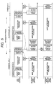
- FIG. 3 is a timing diagram for describing processing for communication between microcomputers and homework calculation processing that are executed with the embodiment
- FIG. 5 is a diagram for illustrating timing relationships between respective processing operations of the main microcomputer and the secondary microcomputer;
- the steering control ECU 60 controls the steering of the vehicle accordingly, to cause the vehicle to travel along the specified lane. More specifically, the steering control ECU 60 performs this steering control only so long as the status information that is transmitted from the vehicle control ECU 50 indicates that the image processing apparatus 10 is operating normally. If the status information indicates that the image processing apparatus 10 is operating abnormally, then the steering control ECU 60 halts the steering control, and the LKA function is terminated.
- the microcomputer 30 executes white line recognition processing for recognizing the shape of lane markers that are located ahead of the vehicle on the road surface (i.e., white lines that appear in the images captured by the camera 11 ), and determines the position relationship between the vehicle and the lane markers.
- the microcomputer 30 thereby derives information expressing the road configuration and the position relationship between the vehicle and the road, as the road parameters, and transmits the obtained road parameters to the microcomputer 20 .
- the microcomputer 20 is configured to execute an “ECU-oriented communication processing task” for communicating with the vehicle control ECU 50 , and a “secondary microcomputer-oriented communication processing task” for communicating with the microcomputer 30 .
- the microcomputer 20 periodically transmits road parameters and diagnostics information to the vehicle control ECU 50 , and also receives vehicle speed information and user actuation information from the vehicle control ECU 50 . Based on these, the microcomputer 20 executes on/off control of the functions of the image processing apparatus 10 .
- FIG. 5 is a diagram showing the time sequence of the processing contents that are executed by the microcomputers 20 and 30 .
- the microcomputer 20 executes the ECU-oriented communication processing task for periodically communicating with the microcomputer 30 at timings in accordance with the aforementioned vertical synchronizing signals.
- the road parameters information obtained by the microcomputer 30 are transmitted by the microcomputer 20 to the vehicle control ECU 50 , together with the results obtained from the abnormality judgement processing (i.e., diagnostics information).
- the microcomputer 30 attempts to set all of the bits of the general-purpose register 31 a to the binary 1 state (all-ones pattern), then executes calculation processing for detecting whether any of these bits remain stuck in the 0 state (step S 231 ), thereby obtaining a calculation result X.
- an initial pattern of all-zeros is set as the value of X, and this is set into the general purpose register 31 a .
- Some simple calculation processing operations involving that register are then performed. Following each of these calculation processing operations, if the result obtained is correct, then the value of X is incremented by one. In that way a condition whereby at least one of the bits of the general purpose register 31 a is stuck in the 0 state can be diagnosed.
- the microcomputer 30 requires an excessive amount of time to perform white line recognition processing, it will not be able to transmit information expressing the most recently derived homework calculation result Y and variable value C to the microcomputer 20 prior to the received data acquisition timing of the microcomputer 20 in the current cycle. In that case, the microcomputer 20 will not be able to acquire updated values for Y and C before performing the abnormality judgement processing in the succeeding cycle (so that a NO decision will be reached in the “data received ?” step of FIG. 7 when the abnormality judgement processing is executed). This condition is illustrated in the timing diagram of FIG. 8 . In that example, in the second cycle, updated values of Y and C cannot be transmitted to the microcomputer 20 before the received data acquisition timing of the microcomputer 20 in that cycle. Hence when the microcomputer 20 performs the abnormality judgement processing routine of FIG. 7 during the third cycle, both the reception error counter Er and the homework calculation error counter Eh will be incremented by one.
- each of the count values attained by the reception error counter Er and the homework calculation error counter Eh will not exceed 1, other than when there is an actual hardware abnormality of the microcomputer 30 or an interruption of communication with the microcomputer 30 .
- Neither of Eh or Er will exceed a count of 1 simply as a result of a 1-cycle transmission delay by the microcomputer 30 .
- the maximum duration of transmission delay is longer, e.g., 2-cycle transmission delay, neither of the counters Eh and Er will exceed a value of 2, during normal operation.
Abstract
Description
Claims (7)
Applications Claiming Priority (2)
| Application Number | Priority Date | Filing Date | Title |
|---|---|---|---|
| JP2007-216157 | 2007-08-22 | ||
| JP2007216157A JP4408921B2 (en) | 2007-08-22 | 2007-08-22 | Electronics |
Publications (2)
| Publication Number | Publication Date |
|---|---|
| US20090055685A1 US20090055685A1 (en) | 2009-02-26 |
| US8091014B2 true US8091014B2 (en) | 2012-01-03 |
Family
ID=40261995
Family Applications (1)
| Application Number | Title | Priority Date | Filing Date |
|---|---|---|---|
| US12/229,188 Expired - Fee Related US8091014B2 (en) | 2007-08-22 | 2008-08-20 | Electronic apparatus in which functioning of a microcomputer is monitored by another microcomputer to detect abnormal operation |
Country Status (3)
| Country | Link |
|---|---|
| US (1) | US8091014B2 (en) |
| EP (1) | EP2053510B1 (en) |
| JP (1) | JP4408921B2 (en) |
Cited By (4)
| Publication number | Priority date | Publication date | Assignee | Title |
|---|---|---|---|---|
| US20140208008A1 (en) * | 2011-09-21 | 2014-07-24 | Hitachi Automotive Systems, Ltd | Electronic control unit for vehicle and data communication method |
| US20160232070A1 (en) * | 2015-02-10 | 2016-08-11 | Robert Bosch Gmbh | Method for operating a data processing unit of a driver assistance system and data processing unit |
| US20180357118A1 (en) * | 2017-06-07 | 2018-12-13 | Hyundai Autron Co., Ltd. | Apparatus and operating method for monitoring micro controller unit having multi-core |
| US11703819B2 (en) * | 2018-11-02 | 2023-07-18 | Mitsubishi Heavy Industries, Ltd. | Unit space update device, unit space update method, and program |
Families Citing this family (9)
| Publication number | Priority date | Publication date | Assignee | Title |
|---|---|---|---|---|
| JP5662181B2 (en) * | 2011-02-01 | 2015-01-28 | 株式会社ケーヒン | Electronic control device for moving body |
| WO2013121545A1 (en) * | 2012-02-15 | 2013-08-22 | トヨタ自動車株式会社 | Vehicle electronic control device and data-receiving method |
| FR2994001B1 (en) | 2012-07-30 | 2015-05-29 | Airbus Operations Sas | METHOD FOR MONITORING THE COORDINATED EXECUTION OF SEQUENCE TASKS BY AN ELECTRONIC CARD COMPRISING AT LEAST TWO PROCESSORS SYNCHRONIZED ON TWO DIFFERENT CLOCKS |
| FR2994000B1 (en) * | 2012-07-30 | 2015-06-05 | Airbus Operations Sas | METHOD FOR MONITORING THE COORDINATED EXECUTION OF SEQUENCE TASKS BY AN ELECTRONIC CARD COMPRISING AT LEAST TWO PROCESSORS SYNCHRONIZED ON THE SAME CLOCK |
| CN108475228A (en) * | 2016-01-27 | 2018-08-31 | 三菱电机株式会社 | Message-based IPC device, Message-based IPC method and Message-based IPC program |
| JP6765874B2 (en) * | 2016-06-30 | 2020-10-07 | 日立オートモティブシステムズ株式会社 | Electronic control device |
| US10558539B2 (en) * | 2017-09-28 | 2020-02-11 | GM Global Technology Operations LLC | Methods and systems for testing components of parallel computing devices |
| JP7091949B2 (en) * | 2018-08-30 | 2022-06-28 | トヨタ自動車株式会社 | Vehicle control unit |
| EP3883235A1 (en) * | 2020-03-17 | 2021-09-22 | Aptiv Technologies Limited | Camera control modules and methods |
Citations (25)
| Publication number | Priority date | Publication date | Assignee | Title |
|---|---|---|---|---|
| JPS5958560A (en) | 1982-09-28 | 1984-04-04 | Japanese National Railways<Jnr> | Diagnosis system of data processor |
| EP0322141A2 (en) | 1987-12-22 | 1989-06-28 | LUCAS INDUSTRIES public limited company | Dual computer cross-checking system |
| JPH06297983A (en) | 1992-07-01 | 1994-10-25 | Mazda Motor Corp | Characteristic changing device for automobile and method thereof |
| DE4446314A1 (en) | 1994-12-23 | 1996-06-27 | Teves Gmbh Alfred | Method and circuit arrangement for monitoring the function of a program-controlled circuit |
| JPH09123894A (en) | 1995-08-25 | 1997-05-13 | Denso Corp | Electronic control device having failure diagnosing function |
| JPH10185189A (en) | 1996-12-26 | 1998-07-14 | Tokyo Gas Co Ltd | Combustor repairing support system |
| JPH10196949A (en) | 1996-12-27 | 1998-07-31 | Tokyo Gas Co Ltd | Combustion equipment repair support apparatus and fault data collecting and utilizing method |
| JP2000293365A (en) | 1999-02-03 | 2000-10-20 | Matsushita Electric Ind Co Ltd | Device for managing program configuration |
| US6230084B1 (en) | 1992-07-01 | 2001-05-08 | Mazda Motor Corporation | Vehicle characteristic change system and method |
| JP2001312315A (en) | 2000-04-28 | 2001-11-09 | Denso Corp | Method for monitoring microcomputer in electronic control device |
| JP2002092214A (en) | 2000-09-19 | 2002-03-29 | Casio Comput Co Ltd | Merchandise information providing device, prize information providing device and storage medium |
| JP2003097344A (en) | 2001-09-27 | 2003-04-03 | Denso Corp | Electronic control device for vehicle |
| US6704933B1 (en) | 1999-02-03 | 2004-03-09 | Masushita Electric Industrial Co., Ltd. | Program configuration management apparatus |
| JP2004259137A (en) | 2003-02-27 | 2004-09-16 | Denso Corp | Electronic control device |
| US20050038581A1 (en) | 2000-08-18 | 2005-02-17 | Nnt, Inc. | Remote Monitoring, Configuring, Programming and Diagnostic System and Method for Vehicles and Vehicle Components |
| US20050060070A1 (en) | 2000-08-18 | 2005-03-17 | Nnt, Inc. | Wireless communication framework |
| US20050065678A1 (en) | 2000-08-18 | 2005-03-24 | Snap-On Technologies, Inc. | Enterprise resource planning system with integrated vehicle diagnostic and information system |
| US20050085963A1 (en) | 2000-08-18 | 2005-04-21 | Nnt, Inc. | Vehicle-interactive system |
| US20050203646A1 (en) | 2004-03-12 | 2005-09-15 | Nobuhiko Makino | Automotive electronic control system including communicably connected commanding unit and driving unit |
| US20050203673A1 (en) | 2000-08-18 | 2005-09-15 | Hassanayn Machlab El-Hajj | Wireless communication framework |
| JP2005258384A (en) | 2003-11-14 | 2005-09-22 | Ricoh Co Ltd | Abnormality determining method, and abnormality determining apparatus and image forming apparatus using the same |
| US7110917B2 (en) | 2003-11-14 | 2006-09-19 | Ricoh Company, Ltd. | Abnormality determining method, and abnormality determining apparatus and image forming apparatus using same |
| US7203431B2 (en) | 2003-12-26 | 2007-04-10 | Ricoh Company, Ltd. | Abnormality determining method, abnormality determining apparatus, and image forming apparatus |
| JP2007293524A (en) | 2006-04-24 | 2007-11-08 | Toyota Motor Corp | Electronic controller and arithmetic function inspection method |
| US7774690B2 (en) * | 2005-07-25 | 2010-08-10 | Nec Electronics Corporation | Apparatus and method for detecting data error |
Family Cites Families (1)
| Publication number | Priority date | Publication date | Assignee | Title |
|---|---|---|---|---|
| JP5255185B2 (en) | 2006-02-17 | 2013-08-07 | 電気化学工業株式会社 | Organophosphorus treatment material and method for treating organophosphorus water using the same |
-
2007
- 2007-08-22 JP JP2007216157A patent/JP4408921B2/en not_active Expired - Fee Related
-
2008
- 2008-08-13 EP EP08014453.8A patent/EP2053510B1/en not_active Expired - Fee Related
- 2008-08-20 US US12/229,188 patent/US8091014B2/en not_active Expired - Fee Related
Patent Citations (33)
| Publication number | Priority date | Publication date | Assignee | Title |
|---|---|---|---|---|
| JPS5958560A (en) | 1982-09-28 | 1984-04-04 | Japanese National Railways<Jnr> | Diagnosis system of data processor |
| EP0322141A2 (en) | 1987-12-22 | 1989-06-28 | LUCAS INDUSTRIES public limited company | Dual computer cross-checking system |
| JPH02138642A (en) | 1987-12-22 | 1990-05-28 | Lucas Ind Plc | Dual computer mutual inspection system |
| JPH06297983A (en) | 1992-07-01 | 1994-10-25 | Mazda Motor Corp | Characteristic changing device for automobile and method thereof |
| US6230084B1 (en) | 1992-07-01 | 2001-05-08 | Mazda Motor Corporation | Vehicle characteristic change system and method |
| DE4446314A1 (en) | 1994-12-23 | 1996-06-27 | Teves Gmbh Alfred | Method and circuit arrangement for monitoring the function of a program-controlled circuit |
| JPH09123894A (en) | 1995-08-25 | 1997-05-13 | Denso Corp | Electronic control device having failure diagnosing function |
| US5897596A (en) | 1995-08-25 | 1999-04-27 | Nippondenso Co., Ltd. | Electronic controller with fault diagnosing function |
| JPH10185189A (en) | 1996-12-26 | 1998-07-14 | Tokyo Gas Co Ltd | Combustor repairing support system |
| JPH10196949A (en) | 1996-12-27 | 1998-07-31 | Tokyo Gas Co Ltd | Combustion equipment repair support apparatus and fault data collecting and utilizing method |
| US6704933B1 (en) | 1999-02-03 | 2004-03-09 | Masushita Electric Industrial Co., Ltd. | Program configuration management apparatus |
| JP2000293365A (en) | 1999-02-03 | 2000-10-20 | Matsushita Electric Ind Co Ltd | Device for managing program configuration |
| US6832337B2 (en) | 2000-04-28 | 2004-12-14 | Denso Corporation | Method and apparatus for monitoring microcomputer in electronic control unit |
| JP2001312315A (en) | 2000-04-28 | 2001-11-09 | Denso Corp | Method for monitoring microcomputer in electronic control device |
| US20050203673A1 (en) | 2000-08-18 | 2005-09-15 | Hassanayn Machlab El-Hajj | Wireless communication framework |
| US7092803B2 (en) | 2000-08-18 | 2006-08-15 | Idsc Holdings, Llc | Remote monitoring, configuring, programming and diagnostic system and method for vehicles and vehicle components |
| US20050038581A1 (en) | 2000-08-18 | 2005-02-17 | Nnt, Inc. | Remote Monitoring, Configuring, Programming and Diagnostic System and Method for Vehicles and Vehicle Components |
| US20050060070A1 (en) | 2000-08-18 | 2005-03-17 | Nnt, Inc. | Wireless communication framework |
| US20050065678A1 (en) | 2000-08-18 | 2005-03-24 | Snap-On Technologies, Inc. | Enterprise resource planning system with integrated vehicle diagnostic and information system |
| US20050085963A1 (en) | 2000-08-18 | 2005-04-21 | Nnt, Inc. | Vehicle-interactive system |
| JP2002092214A (en) | 2000-09-19 | 2002-03-29 | Casio Comput Co Ltd | Merchandise information providing device, prize information providing device and storage medium |
| JP2003097344A (en) | 2001-09-27 | 2003-04-03 | Denso Corp | Electronic control device for vehicle |
| JP2005520725A (en) | 2002-03-04 | 2005-07-14 | エヌエヌティー インク | Vehicle and vehicle component remote monitoring, configuration, programming and diagnostic system and method |
| US7305587B2 (en) * | 2003-02-27 | 2007-12-04 | Denso Corporation | Electronic control unit for monitoring a microcomputer |
| JP2004259137A (en) | 2003-02-27 | 2004-09-16 | Denso Corp | Electronic control device |
| US7110917B2 (en) | 2003-11-14 | 2006-09-19 | Ricoh Company, Ltd. | Abnormality determining method, and abnormality determining apparatus and image forming apparatus using same |
| JP2005258384A (en) | 2003-11-14 | 2005-09-22 | Ricoh Co Ltd | Abnormality determining method, and abnormality determining apparatus and image forming apparatus using the same |
| US7203431B2 (en) | 2003-12-26 | 2007-04-10 | Ricoh Company, Ltd. | Abnormality determining method, abnormality determining apparatus, and image forming apparatus |
| US20070127934A1 (en) | 2003-12-26 | 2007-06-07 | Hisashi Shoji | Abnormality determining method, abnormality determining apparatus, and image forming apparatus |
| JP2005255037A (en) | 2004-03-12 | 2005-09-22 | Denso Corp | Electronic control device for vehicle |
| US20050203646A1 (en) | 2004-03-12 | 2005-09-15 | Nobuhiko Makino | Automotive electronic control system including communicably connected commanding unit and driving unit |
| US7774690B2 (en) * | 2005-07-25 | 2010-08-10 | Nec Electronics Corporation | Apparatus and method for detecting data error |
| JP2007293524A (en) | 2006-04-24 | 2007-11-08 | Toyota Motor Corp | Electronic controller and arithmetic function inspection method |
Non-Patent Citations (2)
| Title |
|---|
| Extended European Search Report dated Jun. 10, 2010 in corresponding EP Application No. 08014453. |
| Office action dated Aug. 4, 2009 in corresponding Japanese Application No. 2007-216157. |
Cited By (8)
| Publication number | Priority date | Publication date | Assignee | Title |
|---|---|---|---|---|
| US20140208008A1 (en) * | 2011-09-21 | 2014-07-24 | Hitachi Automotive Systems, Ltd | Electronic control unit for vehicle and data communication method |
| US9164696B2 (en) * | 2011-09-21 | 2015-10-20 | Hitachi Automotive Systems, Ltd. | Electronic control unit for vehicle and data communication method |
| US9836225B2 (en) | 2011-09-21 | 2017-12-05 | Hitachi Automotive Systems, Ltd. | Electronic control unit for vehicle and data communication method |
| US20160232070A1 (en) * | 2015-02-10 | 2016-08-11 | Robert Bosch Gmbh | Method for operating a data processing unit of a driver assistance system and data processing unit |
| US9875166B2 (en) * | 2015-02-10 | 2018-01-23 | Robert Bosch Gmbh | Method for operating a data processing unit of a driver assistance system and data processing unit |
| US20180357118A1 (en) * | 2017-06-07 | 2018-12-13 | Hyundai Autron Co., Ltd. | Apparatus and operating method for monitoring micro controller unit having multi-core |
| US10684903B2 (en) * | 2017-06-07 | 2020-06-16 | Hyundai Autron Co., Ltd. | Apparatus and operating method for monitoring micro controller unit having multi-core |
| US11703819B2 (en) * | 2018-11-02 | 2023-07-18 | Mitsubishi Heavy Industries, Ltd. | Unit space update device, unit space update method, and program |
Also Published As
| Publication number | Publication date |
|---|---|
| JP2009048556A (en) | 2009-03-05 |
| EP2053510A3 (en) | 2010-07-28 |
| EP2053510B1 (en) | 2017-07-26 |
| EP2053510A2 (en) | 2009-04-29 |
| JP4408921B2 (en) | 2010-02-03 |
| US20090055685A1 (en) | 2009-02-26 |
Similar Documents
| Publication | Publication Date | Title |
|---|---|---|
| US8091014B2 (en) | Electronic apparatus in which functioning of a microcomputer is monitored by another microcomputer to detect abnormal operation | |
| US10866316B2 (en) | Object detection apparatus and object detection method | |
| CN107531250B (en) | Vehicle safety electronic control system | |
| EP3534174A1 (en) | Malfunction detecting device | |
| US10152890B2 (en) | On-vehicle camera device | |
| US9330343B2 (en) | Image analysis apparatus mounted to vehicle | |
| US11511763B2 (en) | Electronic control device | |
| KR101519719B1 (en) | Message process method of gateway | |
| CN110619307A (en) | Traffic light state determination method, device, equipment and storage medium | |
| US10723347B2 (en) | Vehicle control device and vehicle control method | |
| JP2002158668A (en) | Abnormality detector of network system for vehicle | |
| US10106169B2 (en) | Method for monitoring a motor vehicle | |
| US20150195124A1 (en) | Method for error diagnosis of can communication | |
| US9493159B2 (en) | High assurance lane fusion system | |
| JP4539427B2 (en) | Image processing device | |
| CN1893339B (en) | Continuous median failure control system and method | |
| US8688241B2 (en) | Distributed control system for monitoring a significant control | |
| CN111078475B (en) | Visual image data processing system and method and automatic driving automobile | |
| JP2009105549A (en) | Communication apparatus and communication system | |
| KR102195364B1 (en) | Apparatus and Method for Estimating Lane | |
| CN114545893A (en) | Drive-by-wire frame detection method, automatic driving platform and computer readable storage medium | |
| JP2007043398A (en) | Communication system and control method thereof | |
| JP4948583B2 (en) | Control system | |
| CN115136517A (en) | Method and system for performing time synchronization | |
| JP2006195739A (en) | Electronic controller |
Legal Events
| Date | Code | Title | Description |
|---|---|---|---|
| AS | Assignment |
Owner name: DENSO CORPORATION, JAPAN Free format text: ASSIGNMENT OF ASSIGNORS INTEREST;ASSIGNORS:MOCHIDA, KENTARO;NISHII, TAKAHITO;SATOH, YASUHIKO;AND OTHERS;REEL/FRAME:021717/0801;SIGNING DATES FROM 20080826 TO 20080909 Owner name: TOYOTA JIDOSHA KABUSHIKI KAISHA, JAPAN Free format text: ASSIGNMENT OF ASSIGNORS INTEREST;ASSIGNORS:MOCHIDA, KENTARO;NISHII, TAKAHITO;SATOH, YASUHIKO;AND OTHERS;REEL/FRAME:021717/0801;SIGNING DATES FROM 20080826 TO 20080909 Owner name: TOYOTA JIDOSHA KABUSHIKI KAISHA, JAPAN Free format text: ASSIGNMENT OF ASSIGNORS INTEREST;ASSIGNORS:MOCHIDA, KENTARO;NISHII, TAKAHITO;SATOH, YASUHIKO;AND OTHERS;SIGNING DATES FROM 20080826 TO 20080909;REEL/FRAME:021717/0801 Owner name: DENSO CORPORATION, JAPAN Free format text: ASSIGNMENT OF ASSIGNORS INTEREST;ASSIGNORS:MOCHIDA, KENTARO;NISHII, TAKAHITO;SATOH, YASUHIKO;AND OTHERS;SIGNING DATES FROM 20080826 TO 20080909;REEL/FRAME:021717/0801 |
|
| ZAAA | Notice of allowance and fees due |
Free format text: ORIGINAL CODE: NOA |
|
| ZAAB | Notice of allowance mailed |
Free format text: ORIGINAL CODE: MN/=. |
|
| STCF | Information on status: patent grant |
Free format text: PATENTED CASE |
|
| FEPP | Fee payment procedure |
Free format text: PAYOR NUMBER ASSIGNED (ORIGINAL EVENT CODE: ASPN); ENTITY STATUS OF PATENT OWNER: LARGE ENTITY |
|
| FPAY | Fee payment |
Year of fee payment: 4 |
|
| MAFP | Maintenance fee payment |
Free format text: PAYMENT OF MAINTENANCE FEE, 8TH YEAR, LARGE ENTITY (ORIGINAL EVENT CODE: M1552); ENTITY STATUS OF PATENT OWNER: LARGE ENTITY Year of fee payment: 8 |
|
| FEPP | Fee payment procedure |
Free format text: MAINTENANCE FEE REMINDER MAILED (ORIGINAL EVENT CODE: REM.); ENTITY STATUS OF PATENT OWNER: LARGE ENTITY |
|
| LAPS | Lapse for failure to pay maintenance fees |
Free format text: PATENT EXPIRED FOR FAILURE TO PAY MAINTENANCE FEES (ORIGINAL EVENT CODE: EXP.); ENTITY STATUS OF PATENT OWNER: LARGE ENTITY |
|
| STCH | Information on status: patent discontinuation |
Free format text: PATENT EXPIRED DUE TO NONPAYMENT OF MAINTENANCE FEES UNDER 37 CFR 1.362 |
|
| FP | Lapsed due to failure to pay maintenance fee |
Effective date: 20240103 |