US8091456B2 - Safety devices for saws - Google Patents
Safety devices for saws Download PDFInfo
- Publication number
- US8091456B2 US8091456B2 US12/054,881 US5488108A US8091456B2 US 8091456 B2 US8091456 B2 US 8091456B2 US 5488108 A US5488108 A US 5488108A US 8091456 B2 US8091456 B2 US 8091456B2
- Authority
- US
- United States
- Prior art keywords
- saw
- blade
- sensor
- condition
- light
- Prior art date
- Legal status (The legal status is an assumption and is not a legal conclusion. Google has not performed a legal analysis and makes no representation as to the accuracy of the status listed.)
- Expired - Fee Related, expires
Links
- 238000004891 communication Methods 0.000 claims abstract description 10
- 238000000034 method Methods 0.000 description 10
- 230000003287 optical effect Effects 0.000 description 4
- 238000003066 decision tree Methods 0.000 description 3
- 238000001514 detection method Methods 0.000 description 3
- 238000010586 diagram Methods 0.000 description 3
- 239000000428 dust Substances 0.000 description 3
- 239000003086 colorant Substances 0.000 description 2
- 239000000463 material Substances 0.000 description 2
- 230000006978 adaptation Effects 0.000 description 1
- XAGFODPZIPBFFR-UHFFFAOYSA-N aluminium Chemical compound [Al] XAGFODPZIPBFFR-UHFFFAOYSA-N 0.000 description 1
- 229910052782 aluminium Inorganic materials 0.000 description 1
- 238000004458 analytical method Methods 0.000 description 1
- 230000008859 change Effects 0.000 description 1
- 239000004020 conductor Substances 0.000 description 1
- 230000001066 destructive effect Effects 0.000 description 1
- 230000000694 effects Effects 0.000 description 1
- 230000006872 improvement Effects 0.000 description 1
- 239000010985 leather Substances 0.000 description 1
- 238000004519 manufacturing process Methods 0.000 description 1
- 238000012986 modification Methods 0.000 description 1
- 230000004048 modification Effects 0.000 description 1
- 239000013307 optical fiber Substances 0.000 description 1
- 230000008569 process Effects 0.000 description 1
- 239000000523 sample Substances 0.000 description 1
- 238000012306 spectroscopic technique Methods 0.000 description 1
- 238000001228 spectrum Methods 0.000 description 1
Images


Classifications
-
- B—PERFORMING OPERATIONS; TRANSPORTING
- B26—HAND CUTTING TOOLS; CUTTING; SEVERING
- B26D—CUTTING; DETAILS COMMON TO MACHINES FOR PERFORATING, PUNCHING, CUTTING-OUT, STAMPING-OUT OR SEVERING
- B26D7/00—Details of apparatus for cutting, cutting-out, stamping-out, punching, perforating, or severing by means other than cutting
- B26D7/22—Safety devices specially adapted for cutting machines
-
- B—PERFORMING OPERATIONS; TRANSPORTING
- B27—WORKING OR PRESERVING WOOD OR SIMILAR MATERIAL; NAILING OR STAPLING MACHINES IN GENERAL
- B27G—ACCESSORY MACHINES OR APPARATUS FOR WORKING WOOD OR SIMILAR MATERIALS; TOOLS FOR WORKING WOOD OR SIMILAR MATERIALS; SAFETY DEVICES FOR WOOD WORKING MACHINES OR TOOLS
- B27G19/00—Safety guards or devices specially adapted for wood saws; Auxiliary devices facilitating proper operation of wood saws
- B27G19/02—Safety guards or devices specially adapted for wood saws; Auxiliary devices facilitating proper operation of wood saws for circular saws
-
- B—PERFORMING OPERATIONS; TRANSPORTING
- B27—WORKING OR PRESERVING WOOD OR SIMILAR MATERIAL; NAILING OR STAPLING MACHINES IN GENERAL
- B27G—ACCESSORY MACHINES OR APPARATUS FOR WORKING WOOD OR SIMILAR MATERIALS; TOOLS FOR WORKING WOOD OR SIMILAR MATERIALS; SAFETY DEVICES FOR WOOD WORKING MACHINES OR TOOLS
- B27G19/00—Safety guards or devices specially adapted for wood saws; Auxiliary devices facilitating proper operation of wood saws
- B27G19/08—Accessories for keeping open the saw kerf, e.g. riving knives or wedge plates
-
- Y—GENERAL TAGGING OF NEW TECHNOLOGICAL DEVELOPMENTS; GENERAL TAGGING OF CROSS-SECTIONAL TECHNOLOGIES SPANNING OVER SEVERAL SECTIONS OF THE IPC; TECHNICAL SUBJECTS COVERED BY FORMER USPC CROSS-REFERENCE ART COLLECTIONS [XRACs] AND DIGESTS
- Y10—TECHNICAL SUBJECTS COVERED BY FORMER USPC
- Y10S—TECHNICAL SUBJECTS COVERED BY FORMER USPC CROSS-REFERENCE ART COLLECTIONS [XRACs] AND DIGESTS
- Y10S83/00—Cutting
- Y10S83/01—Safety devices
-
- Y—GENERAL TAGGING OF NEW TECHNOLOGICAL DEVELOPMENTS; GENERAL TAGGING OF CROSS-SECTIONAL TECHNOLOGIES SPANNING OVER SEVERAL SECTIONS OF THE IPC; TECHNICAL SUBJECTS COVERED BY FORMER USPC CROSS-REFERENCE ART COLLECTIONS [XRACs] AND DIGESTS
- Y10—TECHNICAL SUBJECTS COVERED BY FORMER USPC
- Y10T—TECHNICAL SUBJECTS COVERED BY FORMER US CLASSIFICATION
- Y10T83/00—Cutting
- Y10T83/202—With product handling means
- Y10T83/2074—Including means to divert one portion of product from another
- Y10T83/2077—By kerf entering guide
-
- Y—GENERAL TAGGING OF NEW TECHNOLOGICAL DEVELOPMENTS; GENERAL TAGGING OF CROSS-SECTIONAL TECHNOLOGIES SPANNING OVER SEVERAL SECTIONS OF THE IPC; TECHNICAL SUBJECTS COVERED BY FORMER USPC CROSS-REFERENCE ART COLLECTIONS [XRACs] AND DIGESTS
- Y10—TECHNICAL SUBJECTS COVERED BY FORMER USPC
- Y10T—TECHNICAL SUBJECTS COVERED BY FORMER US CLASSIFICATION
- Y10T83/00—Cutting
- Y10T83/768—Rotatable disc tool pair or tool and carrier
- Y10T83/7684—With means to support work relative to tool[s]
- Y10T83/773—Work-support includes passageway for tool [e.g., slotted table]
-
- Y—GENERAL TAGGING OF NEW TECHNOLOGICAL DEVELOPMENTS; GENERAL TAGGING OF CROSS-SECTIONAL TECHNOLOGIES SPANNING OVER SEVERAL SECTIONS OF THE IPC; TECHNICAL SUBJECTS COVERED BY FORMER USPC CROSS-REFERENCE ART COLLECTIONS [XRACs] AND DIGESTS
- Y10—TECHNICAL SUBJECTS COVERED BY FORMER USPC
- Y10T—TECHNICAL SUBJECTS COVERED BY FORMER US CLASSIFICATION
- Y10T83/00—Cutting
- Y10T83/849—With signal, scale, or indicator
- Y10T83/85—Signal; e.g., alarm
-
- Y—GENERAL TAGGING OF NEW TECHNOLOGICAL DEVELOPMENTS; GENERAL TAGGING OF CROSS-SECTIONAL TECHNOLOGIES SPANNING OVER SEVERAL SECTIONS OF THE IPC; TECHNICAL SUBJECTS COVERED BY FORMER USPC CROSS-REFERENCE ART COLLECTIONS [XRACs] AND DIGESTS
- Y10—TECHNICAL SUBJECTS COVERED BY FORMER USPC
- Y10T—TECHNICAL SUBJECTS COVERED BY FORMER US CLASSIFICATION
- Y10T83/00—Cutting
- Y10T83/849—With signal, scale, or indicator
- Y10T83/851—Indicator comprising work or product
Definitions
- the present invention generally relates to saws and, more particularly, to safety devices for saws.
- Saws can often include safety devices, or saw accessories, that can protect an operator from being injured while using the saws.
- Table saws for example, can include saw accessories such as a blade guard, a riving knife, and/or one or more anti-kickback pawls.
- a blade guard can be disposed over and/or around a saw blade to reduce the likelihood that the operator may accidentally touch the saw blade.
- a riving knife may be mounted to the saw in alignment with the blade such that the riving knife can be positioned within and/or engage a slot, or kerf, in a workpiece created by the blade.
- the riving knife can prevent, or at least inhibit, portions of the workpiece from pinching onto the blade and, as a result, prevent the workpiece from lifting upwardly or kicking back toward the operator.
- one or more anti-kickback pawls can be attached to the blade guard and/or riving knife, for example, in such a manner as to prevent, or at least inhibit, the workpiece from lifting upwardly by forcing the workpiece against a work surface of the saw.
- an operator may be required to change and/or adjust the saw accessories described above, thereby often exposing the operator's hands, for example, to an area proximate to the blade.
- an operator may often position their hands proximate to the blade as they feed the workpiece through the rotating blade, for example.
- Such saws have not been provided with an indicator which can easily communicate to the operator that the saw is in a powered and/or operating mode, for example, and, as a result, operators have often not been able to readily discern the operating condition of the saw. What is needed is an improvement over the foregoing.
- a saw can include a work surface, a blade at least partially extending through the work surface, at least one sensor, and a light emitter which can be configured to emit a first light beam when the sensor detects a first saw condition and a second light beam when the sensor detects a second saw condition.
- the first light beam can comprise a first color and the second light beam can comprise a second color.
- the sensor can be configured to detect various saw conditions, such as blade speed, for example.
- the sensor configured to detect whether the blade is stationary and/or moving and output a signal indicating the same.
- the light emitter can receive the signal from the sensor and can be configured to emit the first light beam when the sensor detects the blade is stationary and/or, similarly, emit the second light beam when the sensor detects that the blade is moving.
- FIG. 1 is a perspective view of a saw having a plurality of saw accessories and a light emitter attached thereto in accordance with one non-limiting embodiment of the present invention
- FIG. 2 is a partial perspective view of the saw accessories and the light emitter of FIG. 1 ;
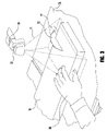
- FIG. 3 is a partial perspective view of the saw accessories and the light emitter of FIG. 2 illustrating an operator's hand positioned on a workpiece;
- FIG. 4 is perspective view of a motor, a drive shaft, an arbor, and a saw blade of the saw of FIG. 1 ;
- FIG. 5 is a perspective view of a saw having a plurality of saw accessories and a light emitter attached thereto in accordance with one non-limiting embodiment of the present invention
- FIG. 6 is a diagram of a circuit used to selectively display first and second lights in accordance with one non-limiting embodiment of the present invention.
- FIG. 7 is a decision tree used by the circuit of FIG. 6 ;
- FIG. 8 is a diagram of a circuit used to selectively display first, second, and third lights in accordance with one non-limiting embodiment of the present invention.
- FIG. 9 is a decision tree used by the circuit of FIG. 8 ;
- FIG. 10 is a diagram of a circuit having a microprocessor, two or more sensors, and a light emitter for selectively displaying first, second, and third lights in accordance with another non-limiting embodiment of the present invention.
- FIG. 11 is a decision tree used by the circuit of FIG. 10 .
- a saw can have a plurality of saw accessories attached thereto where, as described above, the saw accessories can be configured to protect an operator during the operation of the saw, for example.
- saw 10 can include rotatable blade 12 , blade guard 14 , and work surface 16 .
- blade guard 14 can be positioned over and/or around blade 12 such that blade guard 14 can prevent, or at least inhibit, the operator from contacting blade 12 .
- work surface 16 can surround blade 12 and can be configured to support workpiece 18 ( FIG. 3 ) thereon.
- blade 12 can extend through throat plate 17 , wherein the top surface of throat plate 17 can be situated substantially flush with work surface 16 , for example.
- blade 12 can be operably connected to arbor 20 wherein arbor 20 can be operably connected to a first end of drive shaft 22 .
- a second end of drive shaft 22 can be operably connected to actuator, or motor, 24 wherein motor 24 can be configured to rotate drive shaft 22 and, correspondingly, rotate arbor 20 and blade 12 .
- the arbor and/or blade can be motivated in any other suitable fashion such as through the use of a belt drive system, for example.
- saw 10 ′ can include blade 12 ′, blade guard 14 ′, working surface 16 ′, riving knife 26 ′, and at least one anti-kickback pawl 28 ′.
- riving knife 26 ′ can be situated in alignment with the blade 12 ′ such that riving knife 26 ′ can be configured to engage a kerf in workpiece 18 which is created by blade 12 ′ as it passes through the workpiece.
- riving knife 26 ′ can prevent portions of workpiece 18 from pinching onto a portion of blade 12 ′ and being lifted upwardly and/or kicked back toward the operator.
- At least one anti-kickback pawl 28 ′ can be attached to riving knife 26 ′ and/or blade guard 14 ′, wherein pawl 28 ′ can be configured force the workpiece against work surface 16 ′.
- a portion of an outer perimeter of pawl 28 ′ can include teeth 30 ′ which can be configured to engage and grip a top and/or side surface of workpiece 18 and aid in preventing the workpiece from lifting upwardly or kicking back toward the operator.
- a saw can further include a light emitter configured to project at least one visible light beam configured to indicate the condition, or operating mode, of the saw to the operator.
- light emitter 32 can be attached to light emitter holder 34 positioned on blade guard holder 15 .
- light emitter 32 can include at least one light source configured to project or emit light beam 11 , for example, onto at least a portion of work surface 16 which surrounds blade 12 .
- FIG. 1 light emitter 32 can include at least one light source configured to project or emit light beam 11 , for example, onto at least a portion of work surface 16 which surrounds blade 12 .
- light emitter 32 and/or light emitter holder 34 can be attached to blade guard 14 ′, riving knife 26 ′, and/or one of anti-kickback pawls 28 ′, for example.
- the light emitter can include one or more light source, wherein each light source can comprise one or more light bulb, light emitting diode (LED), laser, and/or any other suitable light emitting source configured to project a light, or light beam, onto a portion of the saw such as work surface 16 , for example.
- light emitter 32 can comprise a single light source which can be configured to project two or more different-colored light beams therefrom, for example.
- light beams 11 emitted by light emitter 32 can be configured to indicate when saw 10 is powered, when blade 12 is rotating, and/or when human body part 36 is proximate rotating blade 12 , for example.
- light emitter 32 can include first light source 44 and second light source 46 , for example, where each light source can be configured to emit a different visible light beam in order to indicate a different saw condition.
- the light beam projected from first light source 44 can comprise a green light beam, for example, which can indicate to the operator that blade 12 may be stationary and that it may be safe to work proximate to blade 12 .
- the light beam projected from second light source 46 can comprise a red light beam which can indicate to the operator that the operator should use caution when working around blade 12 as the blade may be rotating.
- any suitable colors, and/or shades or intensities of the same color can be used to indicate whether the blade is stationary and/or moving, for example.
- the first and second light sources can be configured to emit light beams at the same, or substantially the same, location including, for example, an area surrounding blade 12 .
- the light sources can be configured to emit beams directed to different locations on the saw.
- the light sources can be configured to emit light which is not necessarily directed toward a portion of the saw, but is otherwise visible to the operator.
- a light emitter can be used without light emitter holder 34 wherein, in such embodiments, the light emitter can be attached to, or positioned relative to, the saw at any suitable location.
- light emitter 32 and/or light emitter holder 34 can include a reflective shield configured to aid in directing the emitted light beams in a suitable direction, such as downwardly onto work surface 16 and/or workpiece 18 , for example.
- light emitter 32 and/or light emitter holder 34 can further include a power supply in the form of a battery or other suitable light powering source to energize one or more light sources within the light emitter.
- the light sources of light emitter 32 can be powered by actuator, or motor, 24 .
- a saw can include at least one sensor configured to detect a saw condition, such as at least one of the above-described saw conditions, for example, and then transmit an output signal or pulse train to a comparator or a microprocessor, for example, wherein the signal can indicate the saw condition detected.
- comparator 42 can interpret the output signal, or pulse train, from sensor 40 and then output a signal to light emitter 32 , for example.
- comparator 42 can interpret such a signal by comparing the voltage of the signal received from sensor 40 to a base value, such as the voltage which is indicative of a blade speed of zero, for example.
- comparator 42 can output a first signal to first light source 44 of the light emitter, for example, which indicates that the saw blade is stationary, or at least substantially stationary. If the signal received by comparator 42 has a voltage which is larger, or at least sufficiently larger, than the base voltage, then comparator 42 can output a second signal to second light source 46 of the light emitter, for example, which indicates that the blade is moving.
- sensor 40 can be configured to detect a first saw condition and/or a second saw condition of a saw.
- sensor 40 can be placed in communication with a switch which is utilized to operate the saw.
- the switch when the switch has been manipulated into an engaged or ‘on’ position, for example, the switch can complete a signal circuit with motor 24 , for example, wherein sensor 40 can be configured to detect the flow of current through the signal circuit.
- the senor can include a zero-speed sensor, a tachometer, an optical sensor, a digital encoder, and/or any other suitable sensor configured to view or otherwise detect the movement, or the lack of movement, and/or speed of blade 12 , arbor 20 , and/or drive shaft 22 .
- At least one of the blade, drive shaft, arbor, and/or other suitable drive component can include a magnet situated thereon which can be utilized to determine whether the blade is stationary and/or determine the speed of the blade.
- the saw can further include a sensor which can detect the number of times that the magnet passes by the sensor over a predetermined time interval in order to determine the speed of the blade.
- a sensor can be configured to detect teeth located around the outer perimeter of the blade in order to determine whether the blade is moving based on whether intermittent light that may be visible (from the teeth being rotated past the sensor) during a predetermined time interval.
- a tachometer can be operably engaged with blade 12 , arbor 20 , drive shaft 22 , and/or motor 24 , for example, which can be configured detect whether the blade is moving.
- a saw can include a vibration sensor configured to detect a vibration wave produced by the movement of the blade and/or motor of the saw, for example.
- the vibration sensor can be configured to be mounted to one of motor 24 , working surface 16 , and/or any other suitable saw component such that it can, in effect, detect the movement and/or speed of blade 12 .
- the vibration sensor can be configured to detect a first condition, i.e., when no vibration wave is received by the sensor which exceeds a certain threshold level. In such circumstances, the vibration sensor can convey a signal to comparator 42 which can be interpreted such that a first signal is communicated to light emitter 32 to emit a first beam of light.
- the sensor When the sensor detects a vibration level which exceeds the threshold level, the sensor can convey a signal to comparator 42 which can be interpreted such that a second signal is communicated to light emitter 32 to emit a second of beam of light.
- the intensity and/or frequency of the vibration wave, or waves, detected by the sensor can be utilized to determine the velocity of the saw blade.
- sensor 40 can obtain or receive an input signal 50 by viewing or detecting at least one of the moving saw components. Thereafter, sensor 40 can then output signal 52 which can indicate the speed of the saw component to comparator 42 .
- signal 52 has a voltage (X) which is greater than a predetermined constant, or base, voltage for when the blade is in the stationary position
- the comparator 42 can instruct second light source 46 to emit a red light, for example, indicating that blade 12 may be moving.
- comparator 42 can instruct first light source 44 to emit a green light, for example, indicating that the blade may no longer be moving.
- any of the saw components outlined above, including but not limited to, the sensors, the comparator, the microprocessor, and/or the light emitter can be connected to each other through the use of at least one electrical conductor and/or wireless transmitter and receiver.
- the components can be hard wired to each other through any suitable wiring technique such that a first end of a wire can be electrically connected to a first component and the other end of the wire can be electrically connected to a second component, for example.
- at least one of the components can include a transmitter configured to wirelessly output a signal and, in addition, at least one of the components can include a receiver configured to receive the wireless signal.
- a combination of wires and wireless communication devices can be used to allow the saw components to communicate with each other.
- at least some of the saw components such as light emitter 32 , sensor 40 , and comparator 42 , for example, can be placed in electrical communication with power supply 48 , for example, such that power is supplied thereto.
- power supply 48 can include a battery and/or other suitable power source.
- the power supply can be integral to at least one of the saw components.
- output signal 154 can then be communicated to microprocessor 142 , for example, where signal 154 can be interpreted and/or converted into another output signal.
- microprocessor 142 can have at least two voltage threshold levels, which can demarcate three voltage level ranges, for selectively directing the output signal from microprocessor 142 to one of light sources 144 , 146 , and 150 , for example.
- signal 154 has a voltage which is less than voltage threshold level X 1
- microprocessor 142 can output a signal to first light source 144 .
- microprocessor 142 can output a signal to second light source 146 and, correspondingly, if signal 154 has a voltage greater than X 2 , microprocessor 142 can output a signal to third light source 150 .
- light sources 144 , 146 , and 150 can each be configured to emit a light beam.
- first light source 144 can be configured to emit a green light beam
- second light source 146 can be configured to emit a yellow light beam
- third light source 150 can be configured to emit a red light beam, for example.
- green can indicate that no power is available to motor 24
- yellow can indicate that power is available to motor 24 but blade 12 is not rotating
- red can indicate that blade 12 is rotating, for example.
- any suitable light colors or patterns can be utilized to communicate information to the operator.
- at least one of the light sources can be flashed intermittently to communicate a condition of the saw to the operator.
- a flashing light can indicate that a piece of debris is stuck between the saw blade and an adjacent portion of the saw, and/or whether a piece of scrap material or an unsuitable amount of saw dust has been left behind in area proximate to the saw blade.
- a relay interrupting circuit similar to the circuit used to operate the hazard lights on a car, for example.
- the saw conditions indicated by the light emitter can occur when power is available to the saw, when the blade is rotating, as discussed above, and/or when a human body part is detected proximate to the rotating saw blade as discussed below.
- second sensor 240 can be configured to detect human body part 36 and can work in conjunction with, or in lieu of, sensor 40 described above.
- second sensor 240 can be positioned proximate to, or on, light emitter 232 and/or light emitter holder 234 and can be configured to view a portion of work surface 16 proximate to blade 12 such that sensor 240 can obtain input signal 252 wherein input signal 252 can be indicative of whether human body part 36 is proximate to the blade.
- sensor 240 can be positioned at any other suitable location on the saw. In various embodiments, if human body part 36 is detected between sensor 240 and work surface 16 and/or in an area proximate to blade 12 , second sensor 240 can transmit a pulse train or an output signal 254 to microprocessor 242 .
- microprocessor 242 can receive and interpret the pulse train or output signal 254 and then output a signal to light emitter 232 to activate third light source 250 and emit a third light beam, including a third color, onto work surface 16 and/or workpiece 18 .
- the third light beam can indicate to the operator that a portion of their body is within a zone of danger surrounding blade 12 .
- the zone of danger can be defined within or near the perimeter of light beam 11 ( FIG. 3 ), for example.
- an audible alarm can also be provided which can alert the operator of their hand's proximity to blade 12 .
- microprocessor 242 can illuminate the first and second light sources 244 and 246 in a similar fashion as light sources 44 and 46 outlined above.
- power supply 248 can supply power to microprocessor 242 , light emitter 232 , sensor 240 and/or any other suitable saw components.
- microprocessor 242 , light emitter 232 , and sensor 240 can be electrically connected to each other in any suitable manner including those described above.
- second sensor 240 can be, for example, a diffuse reflectance near-infrared sensor utilized in conjunction with a near-infrared source and configured to detect the presence of molecular structures associated with human tissues and/or human body parts.
- the sensor may be configured as a probe included on an optical fiber which may be positioned such that the sensor is configured to detect the presence of the human body part proximate to the blade.
- a reflectance infrared sensor may be utilized with an infrared source, for example.
- the sensor may be remotely positioned from a corresponding light source to allow for increased signal return for the system, to account for a desired angle of return, and to minimize dust interference.
- any suitable electro-optical sensors which utilize various spectroscopic techniques, may be implemented based on cost effectiveness, site conditions, durability, ease of use, reliability, susceptibility to dust interference, and/or for any other suitable reason.
- an Indium-Gallium-Arsenic type sensor may be utilized to detect molecular structures associated with human tissue associated in wavelengths in the near-infrared region of the light spectrum.
- the foregoing system may implement reflectance or diffuse reflectance detection, or in other various embodiments, a particular wavelength, or narrow range of wavelengths, may be selected as representative of the human body part. Additionally, in various embodiments, the sensor may be configured to allow for detection materials commonly used in gloves which may be worn by the operator.
- a range of wavelengths may be selected such that if the operator wears leather gloves, or the like, the sensor may determine if the operator's hand is within a beam of light, for example.
- mirrors may be utilized to focus the returned energy signal (such as from human tissue and/or the workpiece).
- suitable sensors 240 can include reflectance based techniques such as reflectance or diffuse reflectance (e.g., far-infrared, near-infrared, infrared, or a combination thereof) or the like where reflected energy is detected.
- the sensor may include analyzer hardware and/or software for conducting analysis of the return signal.
- an optical proximity device can include a sensor configured to analyze a range of wavelengths to determine the presence of the human body part in the projected light beam.
- a separate analyzer may be included to evaluate the return signal.
- the sensor can scan a range of wavelengths or merely detect in a predetermined wavelength or narrow band of wavelengths. In at least such an embodiment, if a specific wavelength is selected, the source may be simplified or configured to project additional energy at a corresponding energy range.
- sensor 240 can communicate with microprocessor 242 which can then signal light emitter 232 to cause third light source 250 to emit a third light beam, including a third color, onto work surface 16 and/or workpiece 18 to indicate to the operator that their hand is proximate to the blade.
- sensor 240 may, in addition to projecting the third light source, initiate a passive stopping technique such as by turning off the actuator driving the blade for passively preventing the operator from contacting the moving saw blade.
- countermeasure device 300 FIG. 4
- examples of suitable countermeasure devices can include mechanical brakes, electric actuator brakes (preferably in conjunction with turning-off the actuator), sacrificial brakes (e.g., a brake which stops the saw blade by damaging the blade or drive shaft) (for example an aluminum block contacts the blade's teeth), a device which blocks operator contact with the blade, or any other suitable device for actively stopping the blade.
- sensor 240 may be communicatively coupled to actuator 24 in order to prevent the actuator, or motor, from driving blade 12 .
- a solenoid can be activated to drive opposing brake arms to engage the saw blade.
- an optical detector may be configured to initiate a passive stopping technique at a remote position (relative to the saw) and an active technique at a proximal position closer to the blade than the remote position.
- a biasing device which can be arrested by an extended solenoid may be included.
- a brake pad with a sufficiently high coefficient of friction may be utilized to stop the blade without causing damage thereto.
- a pyrotechnic operated mechanical or a sacrificial brake may be utilized.
- an arbor assembly including the arbor, can be constructed such that a solenoid or a pyrotechnic charge may drive the arbor assembly away from the operator (remove the blade from the operator) such as below the work surface. While a passive or non-destructive countermeasure device is disclosed, a sacrificial braking system may also be employed. Those of skill in the art will appreciate that other various devices may be implemented to stop the blade without departing from the scope and spirit of the present disclosure. Further details regarding the human body part detection systems and the various blade stopping techniques described herein can be found in U.S. patent application Ser. No. 10/797,486, which was filed on Mar. 10, 2004 and is entitled OPTICAL PROXIMITY DEVICES FOR POWER TOOLS, the disclosure of which is hereby incorporated by reference herein.
Abstract
Description
Claims (25)
Priority Applications (4)
| Application Number | Priority Date | Filing Date | Title |
|---|---|---|---|
| US12/054,881 US8091456B2 (en) | 2008-03-25 | 2008-03-25 | Safety devices for saws |
| PCT/US2009/037395 WO2009120538A1 (en) | 2008-03-25 | 2009-03-17 | Safety devices for saws |
| US13/306,892 US8479627B2 (en) | 2008-03-25 | 2011-11-29 | Safety devices for saws |
| US13/934,402 US9522475B2 (en) | 2008-03-25 | 2013-07-03 | Safety devices for saws |
Applications Claiming Priority (1)
| Application Number | Priority Date | Filing Date | Title |
|---|---|---|---|
| US12/054,881 US8091456B2 (en) | 2008-03-25 | 2008-03-25 | Safety devices for saws |
Related Child Applications (1)
| Application Number | Title | Priority Date | Filing Date |
|---|---|---|---|
| US13/306,892 Continuation US8479627B2 (en) | 2008-03-25 | 2011-11-29 | Safety devices for saws |
Publications (2)
| Publication Number | Publication Date |
|---|---|
| US20090241748A1 US20090241748A1 (en) | 2009-10-01 |
| US8091456B2 true US8091456B2 (en) | 2012-01-10 |
Family
ID=40790529
Family Applications (3)
| Application Number | Title | Priority Date | Filing Date |
|---|---|---|---|
| US12/054,881 Expired - Fee Related US8091456B2 (en) | 2008-03-25 | 2008-03-25 | Safety devices for saws |
| US13/306,892 Expired - Fee Related US8479627B2 (en) | 2008-03-25 | 2011-11-29 | Safety devices for saws |
| US13/934,402 Active 2028-09-09 US9522475B2 (en) | 2008-03-25 | 2013-07-03 | Safety devices for saws |
Family Applications After (2)
| Application Number | Title | Priority Date | Filing Date |
|---|---|---|---|
| US13/306,892 Expired - Fee Related US8479627B2 (en) | 2008-03-25 | 2011-11-29 | Safety devices for saws |
| US13/934,402 Active 2028-09-09 US9522475B2 (en) | 2008-03-25 | 2013-07-03 | Safety devices for saws |
Country Status (2)
| Country | Link |
|---|---|
| US (3) | US8091456B2 (en) |
| WO (1) | WO2009120538A1 (en) |
Cited By (7)
| Publication number | Priority date | Publication date | Assignee | Title |
|---|---|---|---|---|
| US20100147125A1 (en) * | 2008-12-16 | 2010-06-17 | Georg Stellmann | Power tool |
| US20110226105A1 (en) * | 2008-11-19 | 2011-09-22 | Power Tool Institute | Safety mechanisms for power tools |
| US20120255415A1 (en) * | 2011-04-07 | 2012-10-11 | Robert Bosch Gmbh | Optical Alignment Device For A Table Saw |
| US20120255414A1 (en) * | 2011-04-07 | 2012-10-11 | Robert Bosch Gmbh | Modular Laser Alignment Device for Power Tool |
| US20160318142A1 (en) * | 2013-12-18 | 2016-11-03 | Robert Bosch Gmbh | Skin Sensing using Spectral Analysis |
| US9522475B2 (en) | 2008-03-25 | 2016-12-20 | Power Tool Institute | Safety devices for saws |
| US20230074608A1 (en) * | 2021-09-09 | 2023-03-09 | Nanjing Chervon Industry Co., Ltd. | Table saw |
Families Citing this family (34)
| Publication number | Priority date | Publication date | Assignee | Title |
|---|---|---|---|---|
| US8082826B2 (en) | 2008-03-25 | 2011-12-27 | Power Tool Institute | Saw accessories and clamp for use therewith |
| DE202009000868U1 (en) * | 2009-01-19 | 2009-05-28 | Conder, Karl-Heinz | Table insert for sliding table saws with warning device |
| US8082825B2 (en) | 2009-06-09 | 2011-12-27 | Butler David J | Health and safety system for a table saw |
| EP2319646B1 (en) * | 2009-11-06 | 2012-12-12 | Reika GmbH & Co. KG | Whirling cutting device |
| EP2347846B1 (en) * | 2010-01-20 | 2013-01-09 | Reika GmbH & Co. KG | Circular saw |
| US8534174B2 (en) * | 2010-09-27 | 2013-09-17 | Power Tool Institute | Pyrotechnic actuator and power cutting tool with safety reaction system having such pyrotechnic actuator |
| US20120085214A1 (en) * | 2010-10-08 | 2012-04-12 | Robert Bosch Gmbh | Light guide alignment device for power tool |
| IT1402470B1 (en) * | 2010-11-16 | 2013-09-13 | Biesse Spa | AGGREGATE FOR THE PROCESSING OF WOOD OR SIMILAR COMPONENTS |
| US8950305B1 (en) * | 2011-08-09 | 2015-02-10 | Innovative Engineering Solutions, Inc. | Saw brake |
| DE102011119719A1 (en) * | 2011-11-30 | 2013-06-06 | GEA CFS Bühl GmbH | A method of slicing a food bar using a vibration sensor |
| CN102672644B (en) * | 2012-05-24 | 2014-07-09 | 河北亚大汽车塑料制品有限公司 | Pipe clamping device and assembly machine |
| ITBO20120519A1 (en) * | 2012-09-25 | 2014-03-26 | Biesse Spa | CUTTING MACHINE FOR WOODEN PANELS OR THE LIKE |
| US9519281B2 (en) * | 2012-09-28 | 2016-12-13 | Robert Bosch Tool Corporation | System and method for identification of contact between an object and a static implement in a power tool |
| US9952583B2 (en) * | 2012-09-28 | 2018-04-24 | Robert Bosch Tool Corporation | System and method for identification of implement motion in a power tool |
| US9975269B2 (en) | 2013-03-12 | 2018-05-22 | Robert Bosch Tool Corporation | Guard detection system for a power tool |
| ITMI20150028U1 (en) * | 2015-02-10 | 2016-08-10 | Atom Spa | PERFECT PHOTOELECTRIC SAFETY BARRIER, SPECIES FOR CUTTING MACHINES |
| WO2017014393A1 (en) * | 2015-07-17 | 2017-01-26 | 로얄소브린 인터내셔널 인코퍼레이션 | Cutting machine and method for cutting object to be cut |
| CN105729559A (en) * | 2016-04-12 | 2016-07-06 | 安庆市鸿裕工业产品设计有限公司 | Paper cutter braking protection module based on safe operation |
| CN106238811B (en) * | 2016-08-29 | 2018-01-30 | 成都标建铝业有限公司 | Bridge-cut aluminum section bar sawing machine for cutting |
| CN106141306B (en) * | 2016-08-29 | 2018-01-30 | 成都标建铝业有限公司 | A kind of aluminum section saw cutting machine |
| CN106180882B (en) * | 2016-08-29 | 2018-01-30 | 成都标建铝业有限公司 | Processing unit (plant) for sliding door and window aluminium section bar |
| CN106312568A (en) * | 2016-08-29 | 2017-01-11 | 成都标建铝业有限公司 | Extruding and cutting production line for inswinging casement window profile |
| CN106239162A (en) * | 2016-08-29 | 2016-12-21 | 成都标建铝业有限公司 | A kind of processing tool of Aluminum extrusion cutting one |
| CN106239161A (en) * | 2016-08-29 | 2016-12-21 | 成都标建铝业有限公司 | The process equipment of sliding door and window aluminium section bar |
| CN106239252A (en) * | 2016-08-29 | 2016-12-21 | 成都标建铝业有限公司 | A kind of aluminium saw cutting device |
| CN106271620A (en) * | 2016-08-29 | 2017-01-04 | 成都标建铝业有限公司 | A kind of Aluminum extrusion shaping equipment |
| CN106271653A (en) * | 2016-08-29 | 2017-01-04 | 成都标建铝业有限公司 | Cutting structure for bridge-cut aluminum section bar |
| US10136655B2 (en) * | 2016-10-19 | 2018-11-27 | William M Haack | Saw blade illuminating safety device |
| DE102017201493A1 (en) * | 2017-01-31 | 2018-08-02 | Robert Bosch Gmbh | Circular saw, in particular circular saw |
| US20190234559A1 (en) * | 2018-01-31 | 2019-08-01 | Hollymatic Corporation | Method and system to monitor and shut down saw |
| BE1026458A9 (en) * | 2018-07-09 | 2020-02-10 | Jac S A | AUTOMATIC BREAD SLICER |
| US10865941B2 (en) * | 2018-11-20 | 2020-12-15 | Dennis E. Lewis | Safety system and method for power tools |
| US20220266363A1 (en) * | 2021-02-25 | 2022-08-25 | Nan John Electrical Co., Ltd. | Human-body-defined security recognition system of processing machine |
| US20230191510A1 (en) * | 2021-12-17 | 2023-06-22 | Robert Bosch Gmbh | Blade-Height Optimization Indicator for a Table Saw |
Citations (125)
| Publication number | Priority date | Publication date | Assignee | Title |
|---|---|---|---|---|
| US513138A (en) | 1894-01-23 | Charles g | ||
| US713196A (en) | 1902-05-06 | 1902-11-11 | William B Bennett | Saw-guard. |
| US1082870A (en) | 1912-11-20 | 1913-12-30 | John W Humason | Saw-guard. |
| US1089223A (en) | 1914-01-24 | 1914-03-03 | William Jenkins | Circular-saw guard. |
| US1148169A (en) | 1913-01-06 | 1915-07-27 | Andrew F Howe | Saw-guard. |
| US1255886A (en) | 1915-11-23 | 1918-02-12 | Emerald E Jones | Saw-guard. |
| US1258961A (en) | 1916-03-09 | 1918-03-12 | James G Tattersall | Saw-guard and splitter. |
| US1379802A (en) | 1917-10-01 | 1921-05-31 | Charles A Briggs | Saw-guard |
| US1381612A (en) | 1919-10-24 | 1921-06-14 | George A Anderson | Saw-guard |
| US1465224A (en) | 1921-07-22 | 1923-08-14 | Lantz Joseph Edward | Automatic shield for circular saws |
| US1662372A (en) | 1926-04-26 | 1928-03-13 | Abraham D Ward | Saw guard |
| US1720535A (en) | 1927-12-17 | 1929-07-09 | Calmer G Wold | Automatic guard for saws |
| US1879280A (en) | 1930-08-30 | 1932-09-27 | George V James | Guard for circular saws |
| US1993219A (en) | 1933-07-12 | 1935-03-05 | Herberts Machinery Company Ltd | Circular saw |
| US2007887A (en) | 1933-09-20 | 1935-07-09 | Delta Mfg Co | Saw guard |
| US2095330A (en) | 1936-07-25 | 1937-10-12 | Duro Metal Prod Co | Bench saw |
| US2247314A (en) | 1939-05-31 | 1941-06-24 | Gilbert J Sellmeyer | Portable power driven saw |
| US2328244A (en) | 1941-02-24 | 1943-08-31 | William H Woodward | Circular saw machine |
| US2352235A (en) | 1941-09-10 | 1944-06-27 | Delta Mfg Co | Saw guard |
| US2425331A (en) | 1945-12-13 | 1947-08-12 | Linzie F Kramer | Guard device for circular-saw table sawing machines |
| US2520415A (en) | 1949-05-31 | 1950-08-29 | Bovit David Le | Sewing-machine guide |
| US2524168A (en) | 1948-04-05 | 1950-10-03 | Jr Henry C Harnish | Adjustable pipe square |
| US2530867A (en) | 1949-03-28 | 1950-11-21 | Galanga Charles | Spreaders for circular saw wood cutting machines |
| US2593596A (en) | 1949-03-24 | 1952-04-22 | George V Olson | Circular saw guard |
| US2623555A (en) | 1948-07-14 | 1952-12-30 | Rockwell Mfg Co | Saw guard |
| DE910835C (en) | 1939-09-26 | 1954-05-06 | Leona Pflaumer Geb Steuer | Device for holding the riving knife of a circular saw |
| US2731049A (en) | 1954-06-10 | 1956-01-17 | Orville C Akin | Saw guard assembly for rotary table saws |
| US2913926A (en) | 1957-12-12 | 1959-11-24 | Hammond Machinery Builders Inc | Brush-type guard for printer's saw |
| US3038508A (en) | 1960-09-21 | 1962-06-12 | Lawrence J Moran | Guide for jigsaw blade |
| US3101104A (en) | 1961-03-29 | 1963-08-20 | Weyerhaeuser Co | Safety device for saws |
| US3232326A (en) | 1962-10-04 | 1966-02-01 | Rockwell Mfg Co | Blade guard and splitter assembly for table saws |
| US3302669A (en) | 1964-06-29 | 1967-02-07 | Edler Adolph | Motor powered radial arm tool support |
| US3348836A (en) | 1964-12-21 | 1967-10-24 | Wilton Corp | Clamping means having hydraulic power assisting devices |
| US3609895A (en) | 1969-05-19 | 1971-10-05 | Nicholas Wyckoff | Credit cards |
| US3667990A (en) | 1969-06-18 | 1972-06-06 | May B Rogers | Production of indicia upon surface |
| US3731520A (en) * | 1967-10-05 | 1973-05-08 | Industrial Nucleonics Corp | Dryer performance indicator |
| US3787982A (en) | 1972-04-28 | 1974-01-29 | R Anderson | Direct reading measuring instruments |
| US3851557A (en) | 1973-11-01 | 1974-12-03 | J Vierstraete | Cutting apparatus with work clamp |
| US3949636A (en) | 1975-02-21 | 1976-04-13 | Armstrong Cork Company | Saw guard |
| US4076227A (en) | 1976-05-10 | 1978-02-28 | Trw Inc. | Self-aligning work holding clamp |
| US4370909A (en) | 1981-03-06 | 1983-02-01 | Jennings G Craig | Hand guard for table mounted cutting tool |
| US4418597A (en) | 1982-01-18 | 1983-12-06 | Emerson Electric Co. | Anti-kickback device |
| US4614140A (en) | 1984-05-31 | 1986-09-30 | Macksoud Albert A | Safety device for rocking arm saw |
| US4615247A (en) | 1985-09-13 | 1986-10-07 | Shopsmith, Inc. | Anti-kickback system |
| US4625604A (en) | 1985-06-10 | 1986-12-02 | Hirsh Company | Splitter and blade guard assembly |
| FR2595579A1 (en) | 1986-03-14 | 1987-09-18 | Salomon Sa | SKI PROVIDED WITH PREPERCAGES FOR MOUNTING FIXINGS |
| US4721023A (en) | 1986-06-20 | 1988-01-26 | Shopsmith, Inc. | Saw guard system |
| US5044236A (en) | 1990-01-05 | 1991-09-03 | Continental Machines, Inc. | Nesting vise |
| US5174349A (en) | 1991-08-09 | 1992-12-29 | Skil Corporation | Power table saw assemblies having integral spare part storage |
| US5235752A (en) | 1992-12-23 | 1993-08-17 | Black & Decker Inc. | Riving knife drive mechanism for a portable circular saw |
| US5245903A (en) | 1992-09-01 | 1993-09-21 | Armentrout Raymond C | Shaft cut off gauge |
| US5287779A (en) | 1993-03-15 | 1994-02-22 | Emerson Electric Co. | Radial saw safety guards and barriers |
| US5316061A (en) | 1993-03-16 | 1994-05-31 | Lee Leonard G | Shims for dado cutter set |
| US5317944A (en) | 1991-03-25 | 1994-06-07 | Timothy Hewitt | Adjustable protecting guard apparatus for a blade of a table saw |
| GB2273078A (en) | 1992-12-04 | 1994-06-08 | Black & Decker Inc | Adjustable riving knife |
| US5375495A (en) | 1992-05-18 | 1994-12-27 | Porter-Cable Corporation | Optical alignment system for circular power saws |
| US5447085A (en) | 1994-03-10 | 1995-09-05 | Gochnauer; Marshall | Table saw accessories for improved operability |
| US5461791A (en) | 1994-03-29 | 1995-10-31 | Computational Systems, Inc. | Apparatus and method for rotationally positioning a rotor |
| US5918521A (en) | 1994-11-11 | 1999-07-06 | Sartori; James A. | Bifurcated holdown shoe for radial arm saws |
| US6022010A (en) | 1997-07-11 | 2000-02-08 | Kurt Manufacturing Company, Inc. | Quick change jaw plate |
| US6170370B1 (en) | 1998-08-19 | 2001-01-09 | Sommerville Design & Manufacturing Inc. | Circular saw splitter device with integral anti-kick back |
| US6216575B1 (en) | 1999-02-12 | 2001-04-17 | One World Technologies Inc. | Table saw throat plate with blade height scale |
| US6263584B1 (en) | 1997-08-08 | 2001-07-24 | Barry S. Owens | Alignment apparatus and method of using same |
| US6334380B1 (en) | 2000-01-24 | 2002-01-01 | Duro Machinery Corp. | Clamping device of circular saw |
| US6370997B1 (en) | 1997-06-09 | 2002-04-16 | Elektra Beckum Ag | Transportable bench circular saw |
| US6405624B2 (en) | 1998-07-08 | 2002-06-18 | Delta International Machinery Corp. | Splitter and cutting member guard assembly |
| US6418829B1 (en) | 1994-05-06 | 2002-07-16 | Thomas Stanley Pilchowski | Power tool safety device |
| US6422116B1 (en) | 1998-09-10 | 2002-07-23 | Black & Decker Inc. | Throat plate for a tool |
| US20020170399A1 (en) | 1999-10-01 | 2002-11-21 | Gass Stephen F. | Safety systems for power equipment |
| US6502809B1 (en) | 2001-06-15 | 2003-01-07 | Mark S. Gionta | Workpiece holding fixture |
| WO2003006213A2 (en) | 2001-07-11 | 2003-01-23 | Black & Decker Inc. | Power tool safety mechanisms |
| US6578461B1 (en) | 1999-05-18 | 2003-06-17 | Larry Y. S. Loo | Saw fence and work feed apparatus |
| US6591725B1 (en) | 1999-08-30 | 2003-07-15 | Otto Martin Maschinenbau Gmbh & Co. | Circular sawing machine |
| US20040011177A1 (en) | 2002-07-17 | 2004-01-22 | Durq Machinery Corp. | Quick-detachable blade guard mounting structure |
| US6688202B2 (en) | 1998-02-13 | 2004-02-10 | Black & Decker Inc. | Table saw |
| US20040040169A1 (en) * | 2002-09-03 | 2004-03-04 | Davis Richard Leroy | Power tool alignment device |
| US6715388B1 (en) | 2002-09-28 | 2004-04-06 | Jerome Francis Jaksha | Adjustable splitter and anti-kickback device for power saws |
| US6736042B2 (en) | 2001-03-01 | 2004-05-18 | Porter-Cable Corporation | Work piece guiding system for a table saw |
| US20040118264A1 (en) | 2002-12-24 | 2004-06-24 | Hsin-Chu Chen | Machine for indenting (damaging) the surface of optical discs |
| US20040187666A1 (en) | 2003-03-25 | 2004-09-30 | Durq Machinery Corp. | Table saw |
| US20040194594A1 (en) | 2003-01-31 | 2004-10-07 | Dils Jeffrey M. | Machine safety protection system |
| US6826992B1 (en) | 2003-10-21 | 2004-12-07 | Durq Machinery Corp. | Detachable saw blade guard mounting structure for bench saw |
| US20040246132A1 (en) | 2003-06-05 | 2004-12-09 | Kuo Lung Kuan | Saw cover safety sensing device |
| US20040255745A1 (en) | 2003-06-23 | 2004-12-23 | One World Technologies Limited | Table saw guard assembly |
| US20040261592A1 (en) | 1993-05-18 | 2004-12-30 | Rexon Industrial Corp., Ltd. | Laser guiding device for table saw machine |
| US6900728B2 (en) * | 2002-07-29 | 2005-05-31 | Home Depot U.S.A., Inc. | System to detect user entry into a defined danger zone |
| US20050160895A1 (en) | 2002-10-31 | 2005-07-28 | Garcia Jaime E. | Dual bevel table saw |
| US20050166736A1 (en) | 2004-01-29 | 2005-08-04 | Gass Stephen F. | Table saws with safety systems and systems to mount and index attachments |
| US20050193881A1 (en) | 2004-03-08 | 2005-09-08 | P & F Brother Industrial Corporation | Circular sawing machine with a multi-directional adjustable laser indication device |
| US20050211039A1 (en) | 2004-03-23 | 2005-09-29 | Rexon Industrial Corp., Ltd. | Saw blade guard having illuminator |
| US20050211034A1 (en) | 2004-03-12 | 2005-09-29 | Makita Corporation | Mountings for riving knives of table saws |
| JP2005262337A (en) | 2004-03-16 | 2005-09-29 | Makita Corp | Fixture of riving knife in cutter |
| US20050248303A1 (en) * | 2002-11-22 | 2005-11-10 | Garcia Jaime E | Power tool with remote stop |
| US20050252187A1 (en) | 2000-09-29 | 2005-11-17 | Gass Stephen F | Cutting tool safety system |
| US6986370B1 (en) | 2000-02-01 | 2006-01-17 | Home Depot U.S.A., Inc. | Table saw |
| US20060011034A1 (en) | 2004-07-13 | 2006-01-19 | Gehret Robert S | Riving knife assembly for table saws |
| US20060042441A1 (en) | 2004-08-31 | 2006-03-02 | Makita Corporation | Kickback-inhibiting devices for cutting devices |
| US7013574B2 (en) | 2003-10-14 | 2006-03-21 | Tai Plunkett | Saw blade depth gauge |
| US20060096428A1 (en) | 2003-03-14 | 2006-05-11 | Garcia Jaime E | Riving knife assembly |
| US7044039B2 (en) | 2004-08-31 | 2006-05-16 | Powell Michael S | Radial arm saw safety top |
| US20060101960A1 (en) * | 2003-03-10 | 2006-05-18 | Smith Matthew A | Optical proximity device for power tools |
| US20060101961A1 (en) * | 2002-04-18 | 2006-05-18 | Etter Mark A | Power tool control system |
| US20060101969A1 (en) | 2002-06-19 | 2006-05-18 | Garcia Jaime E | Optical alignment system |
| US7066627B1 (en) | 2004-12-07 | 2006-06-27 | Yueh-Ting Chen | Laser light beam guiding device on a stone cutter |
| US20060155582A1 (en) * | 1992-11-17 | 2006-07-13 | Health Hero Network, Inc. | Modular microprocessor-based power tool system |
| US20060203469A1 (en) | 2005-03-10 | 2006-09-14 | Metabowerke Gmbh | Cutoff/milling device |
| DE202006013323U1 (en) | 2005-08-30 | 2006-11-02 | Yu, Ben | Circular saw bench with adjustable saw cover has guide element connected to spindle that guides sawed workpiece, device that enables spindle to be positioned in relation to holder and saw blade to be fitted and removed |
| US7137327B2 (en) | 2002-10-31 | 2006-11-21 | Black & Decker Inc. | Riving knife assembly for a dual bevel table saw |
| US20060260456A1 (en) | 2005-05-21 | 2006-11-23 | Yueh-Hsun Chang | Protective cover device for a sawing machine |
| US20070056418A1 (en) | 2005-09-13 | 2007-03-15 | Yu-Chuan Lung | Power tool having cabinet |
| US20070056416A1 (en) | 2005-09-15 | 2007-03-15 | Makita Corporation | Cutting devices |
| US7210386B1 (en) | 2005-11-02 | 2007-05-01 | Kingsand Machinery Ltd. | Quickly detachable protective cover unit of a table sawing machine |
| US20070113715A1 (en) | 2005-11-21 | 2007-05-24 | Credo Technology Corporation | Modular guard system for a power saw |
| US20070113714A1 (en) | 2005-11-21 | 2007-05-24 | Credo Technology Corporation And Robert Bosch Gmbh | Modular guard system and apparatus for a power saw |
| US7226179B2 (en) | 2004-06-02 | 2007-06-05 | Black & Decker Inc. | Optical alignment system for power tools |
| US7234380B2 (en) | 2003-01-27 | 2007-06-26 | Black & Decker Inc. | Side pressure splitter |
| US7249992B2 (en) * | 2004-07-02 | 2007-07-31 | Strasbaugh | Method, apparatus and system for use in processing wafers |
| US20070186739A1 (en) | 2006-02-16 | 2007-08-16 | Eastway Fair Company Limited Of Trident Chambers | Riving knife clamp for a table saw |
| US7267038B2 (en) | 1999-06-10 | 2007-09-11 | Black & Decker Inc. | Table saw |
| US20070234584A1 (en) | 2006-04-10 | 2007-10-11 | Antony John Robins | Wall-hanging-aid Device and Method of Use |
| US20080016998A1 (en) * | 2003-04-29 | 2008-01-24 | Keller David V | System and Method for Rapidly Stopping a Spinning Table Saw Blade |
| EP2017025A1 (en) | 2007-07-16 | 2009-01-21 | Black & Decker, Inc. | Riving knife for table Saw |
| US20090241745A1 (en) | 2008-03-25 | 2009-10-01 | Power Tool Institute | Guard, riving knife, and anti-kickback pawl assembly |
| US20090241746A1 (en) | 2008-03-25 | 2009-10-01 | Power Tool Institute | Saw accessories and clamp for use therewith |
| US20100037739A1 (en) * | 2005-06-01 | 2010-02-18 | Anderson Will H | Power cutting tool with overhead sensing system |
Family Cites Families (4)
| Publication number | Priority date | Publication date | Assignee | Title |
|---|---|---|---|---|
| DE3219901A1 (en) * | 1981-10-07 | 1983-04-21 | Rolf 6380 Bad Homburg Susemihl | SAFETY DRIVE FOR AN ELECTRICALLY OPERATED WORKING MACHINE WITH DANGEROUS, MOVING TOOL |
| WO2004041490A2 (en) | 2002-10-31 | 2004-05-21 | Delta International Machinery Corp. | Dual bevel table saw |
| US7171738B2 (en) * | 2003-10-09 | 2007-02-06 | Precision Automation, Inc. | Systems for processing workpieces |
| US8091456B2 (en) | 2008-03-25 | 2012-01-10 | Power Tool Institute | Safety devices for saws |
-
2008
- 2008-03-25 US US12/054,881 patent/US8091456B2/en not_active Expired - Fee Related
-
2009
- 2009-03-17 WO PCT/US2009/037395 patent/WO2009120538A1/en active Application Filing
-
2011
- 2011-11-29 US US13/306,892 patent/US8479627B2/en not_active Expired - Fee Related
-
2013
- 2013-07-03 US US13/934,402 patent/US9522475B2/en active Active
Patent Citations (133)
| Publication number | Priority date | Publication date | Assignee | Title |
|---|---|---|---|---|
| US513138A (en) | 1894-01-23 | Charles g | ||
| US713196A (en) | 1902-05-06 | 1902-11-11 | William B Bennett | Saw-guard. |
| US1082870A (en) | 1912-11-20 | 1913-12-30 | John W Humason | Saw-guard. |
| US1148169A (en) | 1913-01-06 | 1915-07-27 | Andrew F Howe | Saw-guard. |
| US1089223A (en) | 1914-01-24 | 1914-03-03 | William Jenkins | Circular-saw guard. |
| US1255886A (en) | 1915-11-23 | 1918-02-12 | Emerald E Jones | Saw-guard. |
| US1258961A (en) | 1916-03-09 | 1918-03-12 | James G Tattersall | Saw-guard and splitter. |
| US1379802A (en) | 1917-10-01 | 1921-05-31 | Charles A Briggs | Saw-guard |
| US1381612A (en) | 1919-10-24 | 1921-06-14 | George A Anderson | Saw-guard |
| US1465224A (en) | 1921-07-22 | 1923-08-14 | Lantz Joseph Edward | Automatic shield for circular saws |
| US1662372A (en) | 1926-04-26 | 1928-03-13 | Abraham D Ward | Saw guard |
| US1720535A (en) | 1927-12-17 | 1929-07-09 | Calmer G Wold | Automatic guard for saws |
| US1879280A (en) | 1930-08-30 | 1932-09-27 | George V James | Guard for circular saws |
| US1993219A (en) | 1933-07-12 | 1935-03-05 | Herberts Machinery Company Ltd | Circular saw |
| US2007887A (en) | 1933-09-20 | 1935-07-09 | Delta Mfg Co | Saw guard |
| US2095330A (en) | 1936-07-25 | 1937-10-12 | Duro Metal Prod Co | Bench saw |
| US2247314A (en) | 1939-05-31 | 1941-06-24 | Gilbert J Sellmeyer | Portable power driven saw |
| DE910835C (en) | 1939-09-26 | 1954-05-06 | Leona Pflaumer Geb Steuer | Device for holding the riving knife of a circular saw |
| US2328244A (en) | 1941-02-24 | 1943-08-31 | William H Woodward | Circular saw machine |
| US2352235A (en) | 1941-09-10 | 1944-06-27 | Delta Mfg Co | Saw guard |
| US2425331A (en) | 1945-12-13 | 1947-08-12 | Linzie F Kramer | Guard device for circular-saw table sawing machines |
| US2524168A (en) | 1948-04-05 | 1950-10-03 | Jr Henry C Harnish | Adjustable pipe square |
| US2623555A (en) | 1948-07-14 | 1952-12-30 | Rockwell Mfg Co | Saw guard |
| US2593596A (en) | 1949-03-24 | 1952-04-22 | George V Olson | Circular saw guard |
| US2530867A (en) | 1949-03-28 | 1950-11-21 | Galanga Charles | Spreaders for circular saw wood cutting machines |
| US2520415A (en) | 1949-05-31 | 1950-08-29 | Bovit David Le | Sewing-machine guide |
| US2731049A (en) | 1954-06-10 | 1956-01-17 | Orville C Akin | Saw guard assembly for rotary table saws |
| US2913926A (en) | 1957-12-12 | 1959-11-24 | Hammond Machinery Builders Inc | Brush-type guard for printer's saw |
| US3038508A (en) | 1960-09-21 | 1962-06-12 | Lawrence J Moran | Guide for jigsaw blade |
| US3101104A (en) | 1961-03-29 | 1963-08-20 | Weyerhaeuser Co | Safety device for saws |
| US3232326A (en) | 1962-10-04 | 1966-02-01 | Rockwell Mfg Co | Blade guard and splitter assembly for table saws |
| US3302669A (en) | 1964-06-29 | 1967-02-07 | Edler Adolph | Motor powered radial arm tool support |
| US3348836A (en) | 1964-12-21 | 1967-10-24 | Wilton Corp | Clamping means having hydraulic power assisting devices |
| US3731520A (en) * | 1967-10-05 | 1973-05-08 | Industrial Nucleonics Corp | Dryer performance indicator |
| US3609895A (en) | 1969-05-19 | 1971-10-05 | Nicholas Wyckoff | Credit cards |
| US3667990A (en) | 1969-06-18 | 1972-06-06 | May B Rogers | Production of indicia upon surface |
| US3787982A (en) | 1972-04-28 | 1974-01-29 | R Anderson | Direct reading measuring instruments |
| US3851557A (en) | 1973-11-01 | 1974-12-03 | J Vierstraete | Cutting apparatus with work clamp |
| US3949636A (en) | 1975-02-21 | 1976-04-13 | Armstrong Cork Company | Saw guard |
| US4076227A (en) | 1976-05-10 | 1978-02-28 | Trw Inc. | Self-aligning work holding clamp |
| US4370909A (en) | 1981-03-06 | 1983-02-01 | Jennings G Craig | Hand guard for table mounted cutting tool |
| US4418597A (en) | 1982-01-18 | 1983-12-06 | Emerson Electric Co. | Anti-kickback device |
| US4614140A (en) | 1984-05-31 | 1986-09-30 | Macksoud Albert A | Safety device for rocking arm saw |
| US4625604A (en) | 1985-06-10 | 1986-12-02 | Hirsh Company | Splitter and blade guard assembly |
| US4615247A (en) | 1985-09-13 | 1986-10-07 | Shopsmith, Inc. | Anti-kickback system |
| US4747613A (en) | 1986-03-14 | 1988-05-31 | Salomon S.A. | Ski manufactured to have pre-bored screw holes for the mounting of bindings |
| FR2595579A1 (en) | 1986-03-14 | 1987-09-18 | Salomon Sa | SKI PROVIDED WITH PREPERCAGES FOR MOUNTING FIXINGS |
| US4721023A (en) | 1986-06-20 | 1988-01-26 | Shopsmith, Inc. | Saw guard system |
| US5044236A (en) | 1990-01-05 | 1991-09-03 | Continental Machines, Inc. | Nesting vise |
| US5317944A (en) | 1991-03-25 | 1994-06-07 | Timothy Hewitt | Adjustable protecting guard apparatus for a blade of a table saw |
| US5174349A (en) | 1991-08-09 | 1992-12-29 | Skil Corporation | Power table saw assemblies having integral spare part storage |
| US5375495A (en) | 1992-05-18 | 1994-12-27 | Porter-Cable Corporation | Optical alignment system for circular power saws |
| US5245903A (en) | 1992-09-01 | 1993-09-21 | Armentrout Raymond C | Shaft cut off gauge |
| US20060155582A1 (en) * | 1992-11-17 | 2006-07-13 | Health Hero Network, Inc. | Modular microprocessor-based power tool system |
| GB2273078A (en) | 1992-12-04 | 1994-06-08 | Black & Decker Inc | Adjustable riving knife |
| US5235752A (en) | 1992-12-23 | 1993-08-17 | Black & Decker Inc. | Riving knife drive mechanism for a portable circular saw |
| US5287779A (en) | 1993-03-15 | 1994-02-22 | Emerson Electric Co. | Radial saw safety guards and barriers |
| US5316061A (en) | 1993-03-16 | 1994-05-31 | Lee Leonard G | Shims for dado cutter set |
| US20040261592A1 (en) | 1993-05-18 | 2004-12-30 | Rexon Industrial Corp., Ltd. | Laser guiding device for table saw machine |
| US5447085A (en) | 1994-03-10 | 1995-09-05 | Gochnauer; Marshall | Table saw accessories for improved operability |
| US5461791A (en) | 1994-03-29 | 1995-10-31 | Computational Systems, Inc. | Apparatus and method for rotationally positioning a rotor |
| US6418829B1 (en) | 1994-05-06 | 2002-07-16 | Thomas Stanley Pilchowski | Power tool safety device |
| US5918521A (en) | 1994-11-11 | 1999-07-06 | Sartori; James A. | Bifurcated holdown shoe for radial arm saws |
| US6370997B1 (en) | 1997-06-09 | 2002-04-16 | Elektra Beckum Ag | Transportable bench circular saw |
| US6022010A (en) | 1997-07-11 | 2000-02-08 | Kurt Manufacturing Company, Inc. | Quick change jaw plate |
| US6263584B1 (en) | 1997-08-08 | 2001-07-24 | Barry S. Owens | Alignment apparatus and method of using same |
| US6688202B2 (en) | 1998-02-13 | 2004-02-10 | Black & Decker Inc. | Table saw |
| US6405624B2 (en) | 1998-07-08 | 2002-06-18 | Delta International Machinery Corp. | Splitter and cutting member guard assembly |
| US6170370B1 (en) | 1998-08-19 | 2001-01-09 | Sommerville Design & Manufacturing Inc. | Circular saw splitter device with integral anti-kick back |
| US6422116B1 (en) | 1998-09-10 | 2002-07-23 | Black & Decker Inc. | Throat plate for a tool |
| US6543324B2 (en) | 1999-02-12 | 2003-04-08 | One World Technologies, Inc. | Table saw throat plate with blade height scale |
| US6216575B1 (en) | 1999-02-12 | 2001-04-17 | One World Technologies Inc. | Table saw throat plate with blade height scale |
| US6578461B1 (en) | 1999-05-18 | 2003-06-17 | Larry Y. S. Loo | Saw fence and work feed apparatus |
| US7267038B2 (en) | 1999-06-10 | 2007-09-11 | Black & Decker Inc. | Table saw |
| US6591725B1 (en) | 1999-08-30 | 2003-07-15 | Otto Martin Maschinenbau Gmbh & Co. | Circular sawing machine |
| US20020170399A1 (en) | 1999-10-01 | 2002-11-21 | Gass Stephen F. | Safety systems for power equipment |
| US6334380B1 (en) | 2000-01-24 | 2002-01-01 | Duro Machinery Corp. | Clamping device of circular saw |
| US6986370B1 (en) | 2000-02-01 | 2006-01-17 | Home Depot U.S.A., Inc. | Table saw |
| US20050252187A1 (en) | 2000-09-29 | 2005-11-17 | Gass Stephen F | Cutting tool safety system |
| US6736042B2 (en) | 2001-03-01 | 2004-05-18 | Porter-Cable Corporation | Work piece guiding system for a table saw |
| US6502809B1 (en) | 2001-06-15 | 2003-01-07 | Mark S. Gionta | Workpiece holding fixture |
| WO2003006213A2 (en) | 2001-07-11 | 2003-01-23 | Black & Decker Inc. | Power tool safety mechanisms |
| US20060101961A1 (en) * | 2002-04-18 | 2006-05-18 | Etter Mark A | Power tool control system |
| US20060101969A1 (en) | 2002-06-19 | 2006-05-18 | Garcia Jaime E | Optical alignment system |
| US6840144B2 (en) | 2002-07-17 | 2005-01-11 | Durq Machinery Corp. | Quick-detachable blade guard mounting structure |
| US20040011177A1 (en) | 2002-07-17 | 2004-01-22 | Durq Machinery Corp. | Quick-detachable blade guard mounting structure |
| US6900728B2 (en) * | 2002-07-29 | 2005-05-31 | Home Depot U.S.A., Inc. | System to detect user entry into a defined danger zone |
| US20040040169A1 (en) * | 2002-09-03 | 2004-03-04 | Davis Richard Leroy | Power tool alignment device |
| US6715388B1 (en) | 2002-09-28 | 2004-04-06 | Jerome Francis Jaksha | Adjustable splitter and anti-kickback device for power saws |
| US7137327B2 (en) | 2002-10-31 | 2006-11-21 | Black & Decker Inc. | Riving knife assembly for a dual bevel table saw |
| US20050160895A1 (en) | 2002-10-31 | 2005-07-28 | Garcia Jaime E. | Dual bevel table saw |
| US20050248303A1 (en) * | 2002-11-22 | 2005-11-10 | Garcia Jaime E | Power tool with remote stop |
| US20040118264A1 (en) | 2002-12-24 | 2004-06-24 | Hsin-Chu Chen | Machine for indenting (damaging) the surface of optical discs |
| US7234380B2 (en) | 2003-01-27 | 2007-06-26 | Black & Decker Inc. | Side pressure splitter |
| US20040194594A1 (en) | 2003-01-31 | 2004-10-07 | Dils Jeffrey M. | Machine safety protection system |
| US20060101960A1 (en) * | 2003-03-10 | 2006-05-18 | Smith Matthew A | Optical proximity device for power tools |
| US20060096428A1 (en) | 2003-03-14 | 2006-05-11 | Garcia Jaime E | Riving knife assembly |
| US20040187666A1 (en) | 2003-03-25 | 2004-09-30 | Durq Machinery Corp. | Table saw |
| US20080016998A1 (en) * | 2003-04-29 | 2008-01-24 | Keller David V | System and Method for Rapidly Stopping a Spinning Table Saw Blade |
| US20040246132A1 (en) | 2003-06-05 | 2004-12-09 | Kuo Lung Kuan | Saw cover safety sensing device |
| US6853300B2 (en) | 2003-06-05 | 2005-02-08 | Kuo Lung Kuan | Saw cover safety sensing device |
| US20070000366A1 (en) | 2003-06-23 | 2007-01-04 | Peot David G | Table saw guard assembly |
| US20040255745A1 (en) | 2003-06-23 | 2004-12-23 | One World Technologies Limited | Table saw guard assembly |
| US7013574B2 (en) | 2003-10-14 | 2006-03-21 | Tai Plunkett | Saw blade depth gauge |
| US6826992B1 (en) | 2003-10-21 | 2004-12-07 | Durq Machinery Corp. | Detachable saw blade guard mounting structure for bench saw |
| US7827890B2 (en) | 2004-01-29 | 2010-11-09 | Sd3, Llc | Table saws with safety systems and systems to mount and index attachments |
| US20050166736A1 (en) | 2004-01-29 | 2005-08-04 | Gass Stephen F. | Table saws with safety systems and systems to mount and index attachments |
| US20050193881A1 (en) | 2004-03-08 | 2005-09-08 | P & F Brother Industrial Corporation | Circular sawing machine with a multi-directional adjustable laser indication device |
| US7540223B2 (en) | 2004-03-12 | 2009-06-02 | Makita Corporation | Mountings for riving knives of table saws |
| US20050211034A1 (en) | 2004-03-12 | 2005-09-29 | Makita Corporation | Mountings for riving knives of table saws |
| JP2005262337A (en) | 2004-03-16 | 2005-09-29 | Makita Corp | Fixture of riving knife in cutter |
| US20050211039A1 (en) | 2004-03-23 | 2005-09-29 | Rexon Industrial Corp., Ltd. | Saw blade guard having illuminator |
| US7226179B2 (en) | 2004-06-02 | 2007-06-05 | Black & Decker Inc. | Optical alignment system for power tools |
| US7249992B2 (en) * | 2004-07-02 | 2007-07-31 | Strasbaugh | Method, apparatus and system for use in processing wafers |
| US20060011034A1 (en) | 2004-07-13 | 2006-01-19 | Gehret Robert S | Riving knife assembly for table saws |
| US7228773B2 (en) | 2004-08-31 | 2007-06-12 | Powell Michael S | Radial arm saw safety top |
| US20060042441A1 (en) | 2004-08-31 | 2006-03-02 | Makita Corporation | Kickback-inhibiting devices for cutting devices |
| US7044039B2 (en) | 2004-08-31 | 2006-05-16 | Powell Michael S | Radial arm saw safety top |
| US7066627B1 (en) | 2004-12-07 | 2006-06-27 | Yueh-Ting Chen | Laser light beam guiding device on a stone cutter |
| US20060203469A1 (en) | 2005-03-10 | 2006-09-14 | Metabowerke Gmbh | Cutoff/milling device |
| US20060260456A1 (en) | 2005-05-21 | 2006-11-23 | Yueh-Hsun Chang | Protective cover device for a sawing machine |
| US20100037739A1 (en) * | 2005-06-01 | 2010-02-18 | Anderson Will H | Power cutting tool with overhead sensing system |
| DE202006013323U1 (en) | 2005-08-30 | 2006-11-02 | Yu, Ben | Circular saw bench with adjustable saw cover has guide element connected to spindle that guides sawed workpiece, device that enables spindle to be positioned in relation to holder and saw blade to be fitted and removed |
| US20070056418A1 (en) | 2005-09-13 | 2007-03-15 | Yu-Chuan Lung | Power tool having cabinet |
| US20070056416A1 (en) | 2005-09-15 | 2007-03-15 | Makita Corporation | Cutting devices |
| US7210386B1 (en) | 2005-11-02 | 2007-05-01 | Kingsand Machinery Ltd. | Quickly detachable protective cover unit of a table sawing machine |
| US20070113714A1 (en) | 2005-11-21 | 2007-05-24 | Credo Technology Corporation And Robert Bosch Gmbh | Modular guard system and apparatus for a power saw |
| US20070113715A1 (en) | 2005-11-21 | 2007-05-24 | Credo Technology Corporation | Modular guard system for a power saw |
| US20070186739A1 (en) | 2006-02-16 | 2007-08-16 | Eastway Fair Company Limited Of Trident Chambers | Riving knife clamp for a table saw |
| US20070234584A1 (en) | 2006-04-10 | 2007-10-11 | Antony John Robins | Wall-hanging-aid Device and Method of Use |
| EP2017025A1 (en) | 2007-07-16 | 2009-01-21 | Black & Decker, Inc. | Riving knife for table Saw |
| US20090241745A1 (en) | 2008-03-25 | 2009-10-01 | Power Tool Institute | Guard, riving knife, and anti-kickback pawl assembly |
| US20090241746A1 (en) | 2008-03-25 | 2009-10-01 | Power Tool Institute | Saw accessories and clamp for use therewith |
Non-Patent Citations (5)
| Title |
|---|
| Brett-Guard Original Mount Saw Guard printed from http://www.htcproductsinc.com/bgom.html on Jul. 2, 2007, 1 page. |
| Details for Table Saw Pop-In Splitter-Rockler Woodworking Tools, printed from http://www.rockler.com/product.cfm?Offerings-ID=10889&TabSelect=Details, printed Jun. 5, 2007, 3 pages. |
| Details for Table Saw Pop-In Splitter—Rockler Woodworking Tools, printed from http://www.rockler.com/product.cfm?Offerings—ID=10889&TabSelect=Details, printed Jun. 5, 2007, 3 pages. |
| International Preliminary Report on Patentability and Written Opinion of the International Searching Authority issued Sep. 28, 2010 in International Application No. PCT/US2009/037395. |
| International Search Report and Written Opinion mailed Jul. 7, 2009 in International Application No. PCT/US2009/037395. |
Cited By (14)
| Publication number | Priority date | Publication date | Assignee | Title |
|---|---|---|---|---|
| US9522475B2 (en) | 2008-03-25 | 2016-12-20 | Power Tool Institute | Safety devices for saws |
| US8919231B2 (en) * | 2008-11-19 | 2014-12-30 | Power Tool Institute | Safety mechanisms for power tools |
| US20110226105A1 (en) * | 2008-11-19 | 2011-09-22 | Power Tool Institute | Safety mechanisms for power tools |
| US10632642B2 (en) | 2008-11-19 | 2020-04-28 | Power Tool Institute | Table saw with table sensor for sensing characteristic of workpiece |
| US20150075343A1 (en) * | 2008-11-19 | 2015-03-19 | Andy Butler | Safety mechanisms for power tools, including magnetorhelogical brake for blade |
| US8875609B2 (en) * | 2008-12-16 | 2014-11-04 | Robert Bosch Gmbh | Power tool |
| US20100147125A1 (en) * | 2008-12-16 | 2010-06-17 | Georg Stellmann | Power tool |
| US8915170B2 (en) | 2011-04-07 | 2014-12-23 | Robert Bosch Gmbh | Optical alignment device for a table saw |
| US8616102B2 (en) * | 2011-04-07 | 2013-12-31 | Robert Bosch Gmbh | Optical alignment device for a table saw |
| US20120255414A1 (en) * | 2011-04-07 | 2012-10-11 | Robert Bosch Gmbh | Modular Laser Alignment Device for Power Tool |
| US20120255415A1 (en) * | 2011-04-07 | 2012-10-11 | Robert Bosch Gmbh | Optical Alignment Device For A Table Saw |
| US20160318142A1 (en) * | 2013-12-18 | 2016-11-03 | Robert Bosch Gmbh | Skin Sensing using Spectral Analysis |
| US10160080B2 (en) * | 2013-12-18 | 2018-12-25 | Robert Bosch Tool Corporation | Skin sensing using spectral analysis |
| US20230074608A1 (en) * | 2021-09-09 | 2023-03-09 | Nanjing Chervon Industry Co., Ltd. | Table saw |
Also Published As
| Publication number | Publication date |
|---|---|
| US9522475B2 (en) | 2016-12-20 |
| WO2009120538A1 (en) | 2009-10-01 |
| US8479627B2 (en) | 2013-07-09 |
| US20090241748A1 (en) | 2009-10-01 |
| US20120067186A1 (en) | 2012-03-22 |
| US20130291697A1 (en) | 2013-11-07 |
Similar Documents
| Publication | Publication Date | Title |
|---|---|---|
| US9522475B2 (en) | Safety devices for saws | |
| US7681479B2 (en) | Motion detecting system for use in a safety system for power equipment | |
| EP2054193B1 (en) | A manually fed machine for working on materials, objects and the like, and protective means for such a machine | |
| WO2013046522A1 (en) | Cutting machine and emergency stop method of motor | |
| US20060101960A1 (en) | Optical proximity device for power tools | |
| JP5507808B2 (en) | Proximity sensor for stationary power tools | |
| US8154155B2 (en) | Machine tool protection apparatus | |
| US20130187026A1 (en) | Monitoring Device of a Machine Tool | |
| US20120188089A1 (en) | Chain saw hazard warning light | |
| US8432292B2 (en) | Machine tool | |
| US8701534B2 (en) | Machine tool | |
| US20040083869A1 (en) | Guide | |
| JP5279900B2 (en) | Machine tool monitoring device | |
| AU2020274440A1 (en) | Portable machine tool | |
| ES2376400T3 (en) | SUPERVISION UNIT FOR A SUPERVISION AREA IN A TOOL MACHINE. | |
| CN213916448U (en) | Cutting tool | |
| US20180036906A1 (en) | Blade Guard Having a Safety Feature | |
| JP2004331309A (en) | Light projecting device, light receiving device and alarm system for movable object using these devices | |
| KR200425317Y1 (en) | A wireless control device for accident prevention worker | |
| KR20210083819A (en) | Safe guard devie for an elevator checking |
Legal Events
| Date | Code | Title | Description |
|---|---|---|---|
| AS | Assignment |
Owner name: POWER TOOL INSTITUTE, OHIO Free format text: ASSIGNMENT OF ASSIGNORS INTEREST;ASSIGNORS:KELLER, DAVID V.;HICKOK, MARK D.;DOMENY, PETER L.;AND OTHERS;REEL/FRAME:022402/0555;SIGNING DATES FROM 20080305 TO 20080319 Owner name: POWER TOOL INSTITUTE, OHIO Free format text: ASSIGNMENT OF ASSIGNORS INTEREST;ASSIGNORS:KELLER, DAVID V.;HICKOK, MARK D.;DOMENY, PETER L.;AND OTHERS;SIGNING DATES FROM 20080305 TO 20080319;REEL/FRAME:022402/0555 |
|
| ZAAA | Notice of allowance and fees due |
Free format text: ORIGINAL CODE: NOA |
|
| ZAAB | Notice of allowance mailed |
Free format text: ORIGINAL CODE: MN/=. |
|
| ZAAA | Notice of allowance and fees due |
Free format text: ORIGINAL CODE: NOA |
|
| ZAAB | Notice of allowance mailed |
Free format text: ORIGINAL CODE: MN/=. |
|
| STCF | Information on status: patent grant |
Free format text: PATENTED CASE |
|
| FPAY | Fee payment |
Year of fee payment: 4 |
|
| MAFP | Maintenance fee payment |
Free format text: PAYMENT OF MAINTENANCE FEE, 8TH YEAR, LARGE ENTITY (ORIGINAL EVENT CODE: M1552); ENTITY STATUS OF PATENT OWNER: LARGE ENTITY Year of fee payment: 8 |
|
| FEPP | Fee payment procedure |
Free format text: MAINTENANCE FEE REMINDER MAILED (ORIGINAL EVENT CODE: REM.); ENTITY STATUS OF PATENT OWNER: LARGE ENTITY |
|
| LAPS | Lapse for failure to pay maintenance fees |
Free format text: PATENT EXPIRED FOR FAILURE TO PAY MAINTENANCE FEES (ORIGINAL EVENT CODE: EXP.); ENTITY STATUS OF PATENT OWNER: LARGE ENTITY |
|
| STCH | Information on status: patent discontinuation |
Free format text: PATENT EXPIRED DUE TO NONPAYMENT OF MAINTENANCE FEES UNDER 37 CFR 1.362 |
|
| FP | Lapsed due to failure to pay maintenance fee |
Effective date: 20240110 |