US8093499B2 - Cable management system - Google Patents
Cable management system Download PDFInfo
- Publication number
- US8093499B2 US8093499B2 US12/107,897 US10789708A US8093499B2 US 8093499 B2 US8093499 B2 US 8093499B2 US 10789708 A US10789708 A US 10789708A US 8093499 B2 US8093499 B2 US 8093499B2
- Authority
- US
- United States
- Prior art keywords
- cable
- bar
- tie down
- support bracket
- orientation
- Prior art date
- Legal status (The legal status is an assumption and is not a legal conclusion. Google has not performed a legal analysis and makes no representation as to the accuracy of the status listed.)
- Expired - Fee Related, expires
Links
- 230000000712 assembly Effects 0.000 claims description 40
- 238000000429 assembly Methods 0.000 claims description 40
- 238000007726 management method Methods 0.000 description 38
- 230000008520 organization Effects 0.000 description 6
- 239000000463 material Substances 0.000 description 3
- 230000007704 transition Effects 0.000 description 3
- 238000009434 installation Methods 0.000 description 2
- 238000012986 modification Methods 0.000 description 2
- 230000004048 modification Effects 0.000 description 2
- 238000005452 bending Methods 0.000 description 1
- 239000004020 conductor Substances 0.000 description 1
- 239000004744 fabric Substances 0.000 description 1
- 238000002372 labelling Methods 0.000 description 1
- 210000003813 thumb Anatomy 0.000 description 1
- 238000013024 troubleshooting Methods 0.000 description 1
- 239000011800 void material Substances 0.000 description 1
- 238000003466 welding Methods 0.000 description 1
Images


Classifications
-
- H—ELECTRICITY
- H02—GENERATION; CONVERSION OR DISTRIBUTION OF ELECTRIC POWER
- H02G—INSTALLATION OF ELECTRIC CABLES OR LINES, OR OF COMBINED OPTICAL AND ELECTRIC CABLES OR LINES
- H02G3/00—Installations of electric cables or lines or protective tubing therefor in or on buildings, equivalent structures or vehicles
- H02G3/02—Details
- H02G3/04—Protective tubing or conduits, e.g. cable ladders or cable troughs
- H02G3/0456—Ladders or other supports
-
- H—ELECTRICITY
- H04—ELECTRIC COMMUNICATION TECHNIQUE
- H04Q—SELECTING
- H04Q1/00—Details of selecting apparatus or arrangements
- H04Q1/02—Constructional details
- H04Q1/021—Constructional details using pivoting mechanisms for accessing the interior of the apparatus
-
- H—ELECTRICITY
- H04—ELECTRIC COMMUNICATION TECHNIQUE
- H04Q—SELECTING
- H04Q1/00—Details of selecting apparatus or arrangements
- H04Q1/02—Constructional details
- H04Q1/06—Cable ducts or mountings specially adapted for exchange installations
- H04Q1/062—Cable ducts or mountings specially adapted for exchange installations vertical management arrangements
-
- H—ELECTRICITY
- H04—ELECTRIC COMMUNICATION TECHNIQUE
- H04Q—SELECTING
- H04Q1/00—Details of selecting apparatus or arrangements
- H04Q1/02—Constructional details
- H04Q1/06—Cable ducts or mountings specially adapted for exchange installations
- H04Q1/064—Cable ducts or mountings specially adapted for exchange installations horizontal management arrangements
-
- H—ELECTRICITY
- H04—ELECTRIC COMMUNICATION TECHNIQUE
- H04Q—SELECTING
- H04Q1/00—Details of selecting apparatus or arrangements
- H04Q1/02—Constructional details
- H04Q1/06—Cable ducts or mountings specially adapted for exchange installations
- H04Q1/068—Cable ducts or mountings specially adapted for exchange installations arranged on the rear side
-
- H—ELECTRICITY
- H05—ELECTRIC TECHNIQUES NOT OTHERWISE PROVIDED FOR
- H05K—PRINTED CIRCUITS; CASINGS OR CONSTRUCTIONAL DETAILS OF ELECTRIC APPARATUS; MANUFACTURE OF ASSEMBLAGES OF ELECTRICAL COMPONENTS
- H05K7/00—Constructional details common to different types of electric apparatus
- H05K7/18—Construction of rack or frame
- H05K7/186—Construction of rack or frame for supporting telecommunication equipment
Definitions
- the subject matter herein relates generally to cable management systems and, more particularly, to a cable management system for use in equipment racks.
- Standard equipment cabinets or racks such as data communications racks, are typically used to house a number of electrical components, switches, control panels and patch panels. Due to demands for increased capabilities, the panels are designed for an increasing quantity of connections. Once the panels are installed into the rack, the associated wires and cables are connected to the panels. The higher density panels have more connectors and consequently, more or larger associated cabling. In order to properly set-up the equipment rack and properly maintain the connectors, the cables must be installed in an organized manner.
- a cable management system for cable management in an equipment rack.
- the cable management system includes a support bracket having a body extending between a mounting end and a distal end.
- the mounting end is configured to attach to the equipment rack, and the body has a tie down slot configured to receive a cable tie down.
- a cable bar is coupled to the distal end of the support bracket, wherein the cable bar has a tie down slot configured to receive a cable tie down.
- the support bracket and the cable bar define a cable support assembly
- a plurality of cable support assemblies may be provided having support brackets of different lengths such that the cable bars are positioned at different depths from the equipment rack.
- the cable support assemblies may have a tiered arrangement.
- the body is defined by a straight edge and a sloped edge extending between the mounting end and the distal end, wherein the support bracket may be attached to the equipment rack in a first orientation wherein the straight edge is downward facing and a second orientation wherein the straight edge is upward facing such that the cable bar is arranged at a different height when the support bracket is in the first orientation as compared to the second orientation.
- the cable bar may be coupled to the support bracket in a first orientation or a second orientation, wherein the tie down slot of the cable bar extends along a first slot axis when the cable bar is coupled in the first orientation and the tie down slot of the cable bar extends along a second slot axis that is substantially perpendicular to the first slot axis when the cable bar is coupled in the second orientation.
- the cable bar may include a first leg and a second leg, wherein the tie down slot of the cable bar extending through the first leg.
- the cable bar may be oriented such that the first leg is substantially horizontal or such that the first leg is substantially vertical.
- a cable management system for cable management in an equipment rack that includes a first support bracket configured to attach to the equipment rack, wherein the first support bracket has a body having a tie down slot configured to receive a cable tie down.
- a second support bracket is configured to attach to the equipment rack and includes a body having a tie down slot configured to receive a cable tie down.
- the cable management system also includes a cable bar that extends between a first end and a second end. The first end is coupled to the first support bracket and the second end is coupled to the second support bracket.
- the cable bar has a tie down slot configured to receive a cable tie down. At least one of the first end and the second end is removably coupled such that the cable bar may be moved to provide access to a rear of the equipment rack.
- the cable management system may include fasteners that removably couple the cable bar to the first and second support brackets.
- a first fastener may secure the first end to the first support bracket and a second fastener may secure the second end to the second support bracket, wherein when the first fastener is removed, the cable bar is configured to rotate about the second fastener to provide access to a rear of the equipment rack, and wherein when the first and second fasteners are removed, the cable bar is configured to be removed from the first and second support brackets to provide access to a rear of the equipment rack.
- a cable management system for cable management in an equipment rack that includes a first support bracket configured to attach to the equipment rack that has a body having a tie down slot configured to receive a cable tie down and a second support bracket configured to attach to the equipment rack that has a body having a tie down slot configured to receive a cable tie down.
- a cable bar having a tie down slot configured to receive a cable tie down is mountable to the first support bracket and the second support bracket in a first orientation such that the tie down slot is oriented substantially vertically, and the cable bar is mountable to the first support bracket and the second support bracket in a second orientation such that the tie down slot is oriented substantially horizontally.
- the cable bar may have first and second legs defining an L-shaped cross-section, wherein the tie down slot of the cable bar extends through the first leg.
- the first leg is arranged substantially horizontal in the first orientation and the first leg is arranged substantially vertical in the second orientation.
- Each of the first and second legs may include a mounting flange having a leg opening, and the first and second support brackets may each include an attachment flange with a bracket opening.
- the leg openings of the first leg may be aligned with the bracket openings of the first and second support brackets in the first orientation, and the leg openings of the second leg may be aligned with the bracket openings of the first and second support brackets in the second orientation.
- the cable bar may have a longitudinal axis extending along the first and second legs and a transverse axis extending through the first leg, wherein the cable bar is transferred from the first orientation to the second orientation by rotating the cable bar 180 degrees about the longitudinal axis and 90 degrees about the transverse axis.
- FIG. 1 is a rear perspective view of a cable management system having a plurality of cable support assemblies mounted to a distribution assembly.
- FIG. 2 is an exploded front perspective view of one of the cable support assemblies shown in FIG. 1 being assembled in accordance with an exemplary embodiment.
- FIG. 3 is an exploded front perspective view of one of the cable support assemblies being assembled in accordance with an alternative embodiment.
- FIG. 4 is a top view of the cable management system and distribution assembly shown in FIG. 1 with a plurality of cables secured to the cable support assemblies.
- FIG. 5 is a rear perspective view of one of the cable support assemblies shown in FIG. 1 in a partially opened state.
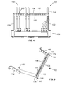
- FIG. 6 is a side view of two of the cable support assemblies in different mounted orientations.
- FIG. 7 illustrates an exemplary group of cable support assemblies.
- FIG. 8 is a side perspective view of a post support bar for use with a four post equipment rack.
- FIG. 9 is a partial rear view of the cable management system and distribution assembly with a plurality of cables secured to the cable support assemblies.
- FIG. 10 is a partial rear perspective view of the cable management system and distribution assembly shown in FIG. 9 .
- FIG. 11 is a partial side perspective view of the cable management system and distribution assembly in accordance with another embodiment.
- FIG. 1 is a rear perspective view of a cable management system 100 having a plurality of cable support assemblies 102 mounted to a distribution assembly 104 .
- the distribution assembly 104 represents a switching network, however, the distribution assembly 104 is merely illustrative and the cable management system 100 may be used with other types of systems/components that distribute or interconnect cables.
- the cable management system 100 provides strain relief, cable organization, and mechanical stability.
- the cable management system 100 is a multi piece solution with variable mounting configurations that support both horizontal and vertical cable management combined into one system.
- the distribution assembly 104 generally includes an equipment rack 106 and a plurality of patch panels 108 arranged in a stacked configuration.
- the patch panels 108 include electronic modules 110 having multiple connector ports 112 .
- Cables 114 (shown in FIG. 4 ) are connected to the connector ports 112 at a rear interface 116 of the patch panels 108 .
- the cables 114 may be grouped together as cable bundles and are routed generally behind the patch panels 108 .
- the cables 114 are managed by the cable management system 100 .
- Each patch panel 108 also receives other cables (not shown) at a front interface 118 of the patch panel 108 .
- the equipment rack 106 includes a pair of posts 120 that are joined by a top plate 122 .
- the patch panels 108 extend between and are coupled to the posts 120 .
- the cable management system 100 includes at least one cable support assembly 102 .
- the cable support assemblies 102 are attached to the posts 120 of the equipment rack 106 .
- the posts 120 include mounting holes 124 on the rear flange 126 and/or the front flange 128 thereof.
- the mounting holes 124 have a predetermined spacing therebetween such that the cable support assemblies 102 may be mounted to any vertical location.
- the cable support assemblies 102 fit into 1 U height requirements.
- the cable support assemblies 102 generally include a first support bracket 130 , a second support bracket 132 and a cable bar 134 extending therebetween. More or fewer support brackets 130 , 132 and/or cable bars 134 may be provided in alternative embodiments.
- the support brackets 130 , 132 are adjustably mounted to the equipment rack 106 and generally extend horizontally and rearwardly from the rear of the equipment rack 106 .
- the support brackets 130 , 132 are adjustably attached to the posts 120 of the equipment rack 106 at adjustable locations to accommodate the specific cable support layout required.
- the support brackets 130 , 132 provide for cable support within the distribution assembly 104 .
- the horizontal cable bar 134 provides a horizontal span between the first and second support brackets 130 , 132 to provide for cable support within the distribution assembly 104 .
- FIG. 2 is an exploded front perspective view of one of the cable support assemblies 102 being mounted to the equipment rack 106 .
- One patch panel 108 is shown mounted to the front flanges 128 of the posts 120 .
- the cable support assembly 102 is mounted to the rear flanges 126 of the posts 120 , and is substantially vertically aligned with the patch panel 108 , however, the cable support assembly 102 may be mounted at any vertical position along the posts 120 .
- Fasteners 140 are used to secure the support brackets 130 , 132 to the posts 120 separate from the patch panel 108 .
- the first support bracket 130 includes a body 142 having a center section 144 extending between a mounting end 146 and a distal end 148 . When coupled to the equipment rack 106 , the distal end 148 is cantilevered from the equipment rack 106 .
- the body 142 has a length 150 that is selected such that the distal end 148 is at a depth from the rear interface 116 .
- different support brackets 130 having different lengths 150 may be provided and used with the cable management system 100 .
- the center section 144 of the body 142 is defined by a straight side 152 and a sloped side 154 that both extend between the mounting end 146 and the distal end 148 .
- the center section 144 has an L-shaped cross section, wherein a flange or lip 156 is provided at the straight side 152 and extends generally inwardly.
- the lip 156 provides rigidity to the center section 144 and may reduce bending or rotation of the center section 144 when the support bracket 130 is placed under load.
- the center section 144 may have a C-shaped cross-section with both the straight side 152 and the sloped side 154 having a flange or lip.
- the sloped side 154 is non-parallel with the straight side 152 and is generally converging toward the straight side 152 from the mounting end 146 . As such, the center section 144 is wider at the mounting end 146 than at the distal end 148 .
- the support bracket 130 is mounted to the equipment rack 106 such that the straight side 152 defines a top side of the support bracket 130 .
- the support bracket 130 is mounted to the equipment rack 106 such that the straight side 152 defines a bottom side of the support bracket 130 .
- Such mounting options provide more flexibility in the location of the mounting of the support bracket 130 .
- the sloped nature of the sloped side 154 provides access or clearance between adjacent support brackets 130 , particularly proximate the distal ends 148 for cables and/or a persons hand or tool to install or remove the cable bar 134 .
- the center section 144 of the support bracket 130 includes a plurality of tie down slots 158 .
- the tie down slots 158 are generally vertically oriented and are sized and shaped to receive cable tie downs 200 (shown in FIG. 4 ) to position and/or secure the cables 114 to the support bracket 130 .
- the tie down slots 158 are spaced apart from one another to define different tie down depths from the rear interface 116 of the patch panel 108 .
- the tie down slots 158 may be oriented non-vertically, such as horizontally or at an angle between vertical and horizontal. The tie down slots 158 allows the cables 114 to be supported and organized along the vertical sides of the equipment rack 106 on the sides of the support bracket 130 .
- the first support bracket 130 includes a rack mounting tab 160 at the mounting end 146 and a rear attachment flange 162 at the distal end 148 .
- the rack mounting tab 160 extends generally perpendicular from the body 142 .
- the rack mounting tab 160 is generally outwardly flared.
- Tab holes 164 are provided in the rack mounting tab 160 and are aligned with the mounting holes 124 in the post 120 .
- the tab holes 164 may be vertically elongated such that the vertical position of the support bracket 130 may be adjusted, such as to align the tab holes 164 with the mounting holes 124 .
- the fasteners 140 extend through the tab holes 164 and the mounting holes 124 to secure the support bracket 130 to the post 120 .
- the rear attachment flange 162 extends along the straight side 152 of the center section 144 proximate to the distal end 148 .
- the rear attachment flange 162 extends generally perpendicular from the center section 144 and is generally inwardly flared.
- the cable bar 134 is attached to the rear attachment flange 162 .
- the rear attachment flange 162 includes a bracket opening 166 extending therethrough.
- the second support bracket 132 is substantially similar to the first support bracket 130 , and like components will hereinafter be designated with like reference numerals.
- the second support bracket 132 is a mirror image of the first support bracket 130 .
- the cable bar 134 is mounted to the rear attachment flanges 162 of the support brackets 130 , 132 , such as by using fasteners 168 .
- FIG. 2 illustrates the cable bar 134 mounted in a first orientation or configuration. While the fasteners 168 are illustrated in FIG. 2 as thumb screws, other types of fasteners may be used in alternative embodiments to securely couple the cable bar 134 to the support brackets 130 , 132 .
- the fastener may be a rivet, a pin, a bolt, a clamp, a tie-down, and the like.
- the cable bar 134 is removably coupled to the support brackets 130 , 132 , such as by releasing or removing the fasteners 168 .
- the cable bar 134 may be permanently coupled to the support brackets 130 , 132 , such as by welding.
- the cable bar 134 is integrally formed with at least one of the support brackets 130 , 132 .
- the cable bar 134 has a generally L-shaped cross-section and includes a first leg 170 and a second leg 172 that extends generally perpendicularly from the first leg 170 .
- the cable bar 134 extends between a first end 174 and a second end 176 . In one orientation, the first end 174 is attached to the first support bracket 130 and the second end 176 is attached to the second support bracket 132 .
- the cable bar 134 includes a first mounting flange 178 at the first end 174 and a second mounting flange 180 at the second end 176 .
- the mounting flanges 178 , 180 extend along both legs 170 , 172 .
- the first mounting flange 178 includes a first leg opening 182 through the first leg 170 and a second leg opening 184 through the second leg 172 .
- the second mounting flange 180 includes a first leg opening 186 through the first leg 170 and a second leg opening 188 (shown in FIG. 3 ) through the second leg 172 .
- the first leg opening 182 at the first end 174 is aligned with the bracket opening 166 in the first support bracket 130 .
- the fastener 168 extends through the first leg opening 182 and the bracket opening 166 to securely couple the first end 174 of the cable bar 134 to the first support bracket 130 .
- the first leg opening 186 at the second end 176 is aligned with the bracket opening 166 in the second support bracket 132 .
- the fastener 168 extends through the first leg opening 186 and the bracket opening 166 to securely couple the second end 174 of the cable bar 134 to the second support bracket 132 .
- a plurality of tie down slots 196 extend through the first leg 170 .
- the tie down slots 196 are elongated in the direction from the second leg 172 to an edge 198 of the first leg 170 .
- the tie down slots 196 are sized and shaped to receive cable tie downs (shown in FIG. 4 ) to position and/or secure the cables 114 to the cable bar 134 .
- the tie down slots 196 are spaced apart from one another to define different tie down locations that are aligned with different areas of the rear interface 116 of the patch panel 108 .
- the tie down slots 196 provide for using a tie down 200 (shown in FIG. 4 ) to attach one or more cables 114 to provide strain relief, support and organization for the cables 114 and the cable bundles.
- the tie down slots 196 are oriented generally horizontally along a horizontal plane defined by the first leg 170 .
- FIG. 3 is an exploded front perspective view of the same cable support assembly 102 illustrated in FIG. 2 , but being assembled differently than in the embodiment shown in FIG. 2 .
- the cable support assembly 102 is attached to front flanges 128 of the posts 120 .
- the same fasteners 140 are used to secure the patch panel 108 and the support brackets 130 , 132 .
- the rear attachment flanges 162 of the support brackets 130 , 132 are located at a different, shallower, depth from the rear interface 116 of the patch panel 108 , as compared to the embodiment shown in FIG. 2 , as at least a portion of the patch panel 108 extends along the body 142 .
- the cable bar 134 is attached to the support brackets 130 , 132 in a second orientation or configuration.
- the second orientation is generally flipped with respect to the first orientation such that the tie down slots 196 are oriented substantially vertically as opposed to horizontally as in the first orientation.
- the first leg 170 is oriented generally vertically and the second leg 172 is oriented generally horizontally.
- the first end 174 is attached to the second support bracket 132 and the second end 176 is attached to the first support bracket 130 .
- the cable bar 134 includes a longitudinal axis 190 extending along the first and second legs 170 , 172 .
- the first and second legs 170 , 172 are parallel to the longitudinal axis 190 .
- a first transverse axis 192 extends through the first leg 170 and is perpendicular to the longitudinal axis 190 .
- the second leg 172 is parallel to the first transverse axis 192 .
- a second transverse axis 194 extends through the second leg 172 and is perpendicular to the longitudinal axis 190 and the first transverse axis 192 .
- the first leg 170 is parallel to the second transverse axis 194 .
- the cable bar 134 may be rotated about the longitudinal axis 190 approximately 180 degrees and the cable bar 134 may be rotated about one of the transverse axes 192 , 194 approximately 90 degrees to transition the cable bar 134 from the first orientation to the second orientation, and vice versa.
- the second leg opening 184 at the first end 174 is aligned with the bracket opening 166 in the second support bracket 132 .
- the fastener 168 extends through the first leg opening 184 and the bracket opening 166 to securely couple the first end 174 of the cable bar 134 to the second support bracket 132 .
- the second leg opening 188 at the second end 176 is aligned with the bracket opening 166 in the first support bracket 130 .
- the fastener 168 extends through the second leg opening 188 and the bracket opening 166 to securely couple the second end 176 of the cable bar 134 to the first support bracket 130 .
- the leg openings 182 , 184 , 186 and 188 allow the cable bar 134 to be mounted to the support brackets 130 , 132 in either the first orientation (shown in FIG. 2 ) or in the second orientation (shown in FIG. 3 ).
- first orientation shown in FIG. 2
- second orientation shown in FIG. 3
- first leg 170 is the horizontal leg and the second leg 172 is the vertical leg.
- first leg 170 is the vertical leg and the second leg 172 as the horizontal leg.
- the tie down slots 196 in the first leg 170 may be located on the top surface of the mounted horizontal cable bar 134 or the rear surface of the horizontal cable bar 134 .
- the flexible mounting scheme of the cable bar 134 provides both horizontal and vertical strain relief and management and, provides both top and back attachment of the cables providing easy access to the electrical equipment or panels for installation and removal of the cables during replacement or trouble shooting.
- Each of the components of the cable support assemblies 102 may include features, such as plates, tags, or other means for labeling cables and cable bundles to provide further organization within the equipment rack.
- FIG. 4 is a top view of the cable management system 100 and equipment rack 106 with a plurality of cables 114 secured to the cable support assemblies 102 .
- the cable bar 134 is coupled to the support brackets 130 , 132 such that the first leg 170 and the tie down slots 196 are oriented horizontally. Some of the cables 114 are secured to the top of the cable bar 134 , while some of the cables 114 are secured to the bottom of the cable bar 134 .
- tie downs 200 extend through the tie down slots 196 and wrap around the cables 114 to secure the cables against the cable bar 134 .
- the tie downs 200 may be plastic strips that are self-securing, such as zip ties, tie wraps, straps, clips, and the like.
- the tie downs 200 may be a strap, such as of a cloth material, having a fastener at least one of the ends, such as a hook and loop fastener.
- some of the cables 114 are secured to the second support bracket 132 rather than the cable bar 134 .
- Tie downs 200 are again used to extend through the tie down slots 158 (shown in FIG. 2 ) to secure the cables 114 to the support bracket 132 .
- the cables 114 may be run along either the inside or the outside of the support bracket 132 .
- FIG. 5 is a rear perspective view of one of the cable support assemblies 102 in a partially opened state.
- the cable bar 134 may be moved to provide access to the rear interface 116 (shown in FIG. 1 ) of the equipment rack 106 (shown in FIG. 1 ).
- the cable bar 134 may be rotated about either the first end 174 or the second end 176 , such as by removing one of the fastener 168 , such as the fastener securing the second end 176 to the second support bracket 132 . Once the fastener 168 is released or removed, the cable bar 134 may be pivoted or rotated about the fastener 168 securing the first end 174 to the first support bracket 130 .
- the rear interface 116 may be accessed.
- the entire cable bar 134 may be removed from the support brackets 130 , 132 .
- both fasteners 168 may be released or removed and then the cable bar 134 may be removed. Once removed, the rear interface 116 may be accessed.
- the leg openings 182 and 188 are elongated in the direction from the second leg 172 to the edge 198 of the first leg 170 .
- FIG. 6 is a side view of two of the cable support assemblies 102 in different mounted orientations.
- the upper cable support assembly 102 is normally mounted to the equipment rack 106
- the lower cable support assembly 102 is reverse, or upside-down, mounted to the equipment rack 106 .
- the straight side 152 is the top of the support bracket 130 and the sloped side 154 is the bottom of the support bracket 130 .
- the sloped side 154 is the top of the support bracket 130 and the straight side 152 is the bottom of the support bracket 130 .
- the cable bars 134 are attached to the straight sides 152 of support brackets 130 .
- the vertical positions of the cable bars 134 can be controlled.
- the cable bar 134 in the normally mounted position, the cable bar 134 is generally aligned with the top of the mounting end 146 , whereas in the reverse mounted position, the cable bar 134 is generally aligned with the bottom of the mounting end 146 .
- the cable bars 134 may be further spaced from one another as compared to a situation in which both cable support assemblies 102 are mounted in the same orientation.
- Such mounting options provides more flexibility in the location of the supporting elements for the cables 114 (shown in FIG. 4 ).
- FIG. 7 illustrates an exemplary group of cable support assemblies 102 .
- FIG. 7 illustrates that different sized support brackets 130 may be provided.
- the center sections 144 of the support brackets 130 may have different lengths 150 .
- FIG. 7 illustrates three different sized support brackets 130 having center section lengths 150 of for example, six inches, nine inches, and twelve inches.
- support brackets 130 of any length may be used, including support brackets 130 having lengths longer than twelve inches or shorter than six inches.
- the variable length of the support brackets 130 provides for variable depths of the cable support assemblies 102 when used together and mounted to the equipment rack 106 (shown in FIG. 1 ).
- one cable support assembly 102 may have a support bracket 130 with a length 150 of six inches, cable support assembly 102 may have a support bracket 130 with a length 150 of nine inches and a further cable support assembly 102 may have a support bracket 130 with a length 150 of twelve inches.
- the cable management system 100 shown in FIG. 1
- FIG. 8 is a side perspective view of a post support bar 210 for use with a four post equipment rack (not shown).
- the post support bar 210 mounts substantially horizontally between two posts within the four post equipment rack and may be mounted in any vertical location in standard equipment racks.
- the post support bar 210 mounts between a front post and a back post of a four post equipment rack to provide post support and/or cable support on the sides of the equipment rack.
- the post support bar 210 includes mounting flanges 212 at each end thereof and a spanning section 214 between the mounting flanges 212 .
- the spanning section 214 has a C-shaped cross-section.
- the spanning section 214 includes a plurality of tie down slots 216 for placement of tie downs 200 (shown in FIG. 4 ) to support cables 114 (shown in FIG. 4 ).
- the tie down slots 216 may be substantially vertically oriented.
- the post support bar 210 provides support and organization of vertical cable runs without impeding installation of the cable support assemblies 102 (shown in FIG. 1 ) and additional cables 114 .
- FIG. 9 is a partial rear view of the cable management system 100 and equipment rack 106 with a plurality of cables 114 secured to the cable support assemblies 102 .
- FIG. 10 is a partial rear perspective view of the cable management system 100 and equipment rack 106 shown in FIG. 9 .
- five cable bundles are shown, wherein each cable bundle includes more than one cable 114 .
- the cable bundles are identified as cable bundles 220 , 222 , 224 , 226 and 228 .
- the cable support assemblies are identified as cable support assemblies 230 , 232 and 234 .
- Each cable support assembly 230 , 232 and 234 is sized differently.
- the first, or upper, cable support assembly 230 has support brackets with a length of six inches.
- the second, or middle, cable support assembly 232 has support brackets with a length of nine inches.
- the third, or lower, cable support assembly 234 has support brackets with a length of twelve inches.
- the cable support assemblies thus provide a tiered approach for cable management.
- the cable bars of the upper and middle cable support assemblies 230 , 232 are in a first orientation such that the tie down slots 196 are horizontally oriented.
- the cable bar of the lower cable support assembly 234 is in a second orientation such that the tie down slots 196 are vertically oriented.
- the first cable bundle 220 is secured to the cable bar of the lower cable support assembly 234 using a tie down 200 . All of the cables 114 in the first cable bundle 220 extend along the outside of the cable bar. The first cable bundle 220 is also secured to the cable bar of the upper cable support assembly 230 using another tie down 200 . Some of the cables 114 in the first cable bundle 220 extend along the top of the cable bar and some of the cables 114 in the first cable bundle 220 extend along the bottom of the cable bar.
- the second cable bundle 222 is secured to the cable bar of the middle cable support assembly 232 using a tie down 200 . All of the cables 114 in the second cable bundle 222 extend along the bottom of the cable bar.
- the third cable bundle 224 is secured to the cable bar of the lower cable support assembly 234 using a tie down 200 . All of the cables 114 in the third cable bundle 224 extend along the outside of the cable bar. The third cable bundle 224 is also secured to the cable bar of the upper cable support assembly 230 using another tie down 200 . Some of the cables 114 in the third cable bundle 224 extend along the top of the cable bar and some of the cables 114 in the third cable bundle 224 extend along the bottom of the cable bar. The fourth cable bundle 226 is secured in a similar manner as the third cable bundle 224 .
- the fifth cable bundle 228 is secured to the bracket support 130 of the lower cable support assembly 234 using a tie down 200 . All of the cables 114 in the fifth cable bundle 228 extend along the outside of the bracket support 130 . The fifth cable bundle 228 is also secured to the cable bar of the upper cable support assembly 230 using another tie down 200 . All of the cables 114 in the fifth cable bundle 228 extend along the top of the cable bar.
- the cable management system 100 thus provides strain relief, cable organization, and mechanical stability.
- the various mounting configurations of the cable tie downs 200 support both horizontal and vertical cable management combined into one system.
- the support brackets may be adjustably attached to the equipment rack 106 at adjustable locations to accommodate the specific cable support layout required.
- FIG. 11 is a partial side perspective view of the cable management system 100 and equipment rack 106 having a different arrangement of cable support assemblies 102 and cables 114 than the embodiment illustrated in FIGS. 9 and 10 .
- four cable bundles are shown, wherein each cable bundle includes more than one cable 114 .
- the cable bundles are identified as cable bundles 240 , 242 , 244 and 246 .
- the cable support assemblies are identified as cable support assemblies 250 , 252 , 254 and 256 .
- the cable support assemblies 254 and 256 are sized the same as one another, but are sized differently than the cable support assemblies 250 and 252 .
- the first, or upper, cable support assembly 250 has support brackets with a length of six inches.
- the second, or upper-middle, cable support assembly 252 has support brackets with a length of nine inches.
- the third, or lower-middle, cable support assembly 254 and the fourth, or lower, cable support assembly 256 both have support brackets with a length of twelve inches.
- the cable support assemblies thus provide a tiered approach for cable management.
- Each of the cable bundles 240 , 242 , 244 and 246 are secured to the support bracket 130 of the lower cable support assembly 256 using tie downs 200 .
- the first and second cable bundles 240 , 242 are both secured to the support bracket 130 of the lower-middle cable support assembly 254 using a common tie down 200 .
- the cable management system 100 thus provides strain relief, cable organization, and mechanical stability.
- the various mounting configurations of the cable ties 200 support both horizontal and vertical cable management combined into one system.
- the support brackets may be adjustably attached to the equipment rack 106 at adjustable locations to accommodate the specific cable support layout required.
Abstract
Description
Claims (20)
Priority Applications (1)
| Application Number | Priority Date | Filing Date | Title |
|---|---|---|---|
| US12/107,897 US8093499B2 (en) | 2008-04-23 | 2008-04-23 | Cable management system |
Applications Claiming Priority (1)
| Application Number | Priority Date | Filing Date | Title |
|---|---|---|---|
| US12/107,897 US8093499B2 (en) | 2008-04-23 | 2008-04-23 | Cable management system |
Publications (2)
| Publication Number | Publication Date |
|---|---|
| US20090266607A1 US20090266607A1 (en) | 2009-10-29 |
| US8093499B2 true US8093499B2 (en) | 2012-01-10 |
Family
ID=41213878
Family Applications (1)
| Application Number | Title | Priority Date | Filing Date |
|---|---|---|---|
| US12/107,897 Expired - Fee Related US8093499B2 (en) | 2008-04-23 | 2008-04-23 | Cable management system |
Country Status (1)
| Country | Link |
|---|---|
| US (1) | US8093499B2 (en) |
Cited By (44)
| Publication number | Priority date | Publication date | Assignee | Title |
|---|---|---|---|---|
| US20110309591A1 (en) * | 2010-06-17 | 2011-12-22 | Bretford Manufacturing, Inc. | Computer Cart |
| US20120288248A1 (en) * | 2011-05-09 | 2012-11-15 | Erika Guadalupe Chapa Ramirez | Attachment mechanisms employed to attach a rear housing section to a fiber optic housing, and related assemblies and methods |
| US8391663B2 (en) * | 2011-05-24 | 2013-03-05 | Methode Electronics, Inc. | Rack cabling system |
| US8879881B2 (en) | 2010-04-30 | 2014-11-04 | Corning Cable Systems Llc | Rotatable routing guide and assembly |
| US8913866B2 (en) | 2010-03-26 | 2014-12-16 | Corning Cable Systems Llc | Movable adapter panel |
| US8953924B2 (en) | 2011-09-02 | 2015-02-10 | Corning Cable Systems Llc | Removable strain relief brackets for securing fiber optic cables and/or optical fibers to fiber optic equipment, and related assemblies and methods |
| US8965168B2 (en) | 2010-04-30 | 2015-02-24 | Corning Cable Systems Llc | Fiber management devices for fiber optic housings, and related components and methods |
| US8985862B2 (en) | 2013-02-28 | 2015-03-24 | Corning Cable Systems Llc | High-density multi-fiber adapter housings |
| US8989547B2 (en) | 2011-06-30 | 2015-03-24 | Corning Cable Systems Llc | Fiber optic equipment assemblies employing non-U-width-sized housings and related methods |
| US8992099B2 (en) | 2010-02-04 | 2015-03-31 | Corning Cable Systems Llc | Optical interface cards, assemblies, and related methods, suited for installation and use in antenna system equipment |
| US8995812B2 (en) | 2012-10-26 | 2015-03-31 | Ccs Technology, Inc. | Fiber optic management unit and fiber optic distribution device |
| US9020320B2 (en) | 2008-08-29 | 2015-04-28 | Corning Cable Systems Llc | High density and bandwidth fiber optic apparatuses and related equipment and methods |
| US9022814B2 (en) | 2010-04-16 | 2015-05-05 | Ccs Technology, Inc. | Sealing and strain relief device for data cables |
| US9038832B2 (en) | 2011-11-30 | 2015-05-26 | Corning Cable Systems Llc | Adapter panel support assembly |
| US9042702B2 (en) | 2012-09-18 | 2015-05-26 | Corning Cable Systems Llc | Platforms and systems for fiber optic cable attachment |
| US9075217B2 (en) | 2010-04-30 | 2015-07-07 | Corning Cable Systems Llc | Apparatuses and related components and methods for expanding capacity of fiber optic housings |
| US9116324B2 (en) | 2010-10-29 | 2015-08-25 | Corning Cable Systems Llc | Stacked fiber optic modules and fiber optic equipment configured to support stacked fiber optic modules |
| USD739358S1 (en) * | 2014-03-24 | 2015-09-22 | Cellular Specialties, Inc. | Cable management tray |
| US9213161B2 (en) | 2010-11-05 | 2015-12-15 | Corning Cable Systems Llc | Fiber body holder and strain relief device |
| US9250409B2 (en) | 2012-07-02 | 2016-02-02 | Corning Cable Systems Llc | Fiber-optic-module trays and drawers for fiber-optic equipment |
| US9279951B2 (en) | 2010-10-27 | 2016-03-08 | Corning Cable Systems Llc | Fiber optic module for limited space applications having a partially sealed module sub-assembly |
| US20160211687A1 (en) * | 2015-01-19 | 2016-07-21 | Aver Information Inc. | Charging apparatus, charging device and cable management member |
| US9429251B1 (en) | 2015-08-31 | 2016-08-30 | Jyh Eng Technology Co., Ltd. | Foldable electrical wire organizer assembly |
| US20160302325A1 (en) * | 2012-09-14 | 2016-10-13 | Hoffman Enclosures, Inc. | Center Pivot Swing-Out Wall Rack |
| US9519118B2 (en) | 2010-04-30 | 2016-12-13 | Corning Optical Communications LLC | Removable fiber management sections for fiber optic housings, and related components and methods |
| US9645317B2 (en) | 2011-02-02 | 2017-05-09 | Corning Optical Communications LLC | Optical backplane extension modules, and related assemblies suitable for establishing optical connections to information processing modules disposed in equipment racks |
| US9703061B1 (en) * | 2015-06-25 | 2017-07-11 | Amazon Technologies, Inc. | Switch or router optic replacement device |
| US20170223860A1 (en) * | 2014-07-31 | 2017-08-03 | Hewlett Packard Enterprise Development Lp | Front cable management assembly |
| US20170353024A1 (en) * | 2014-12-19 | 2017-12-07 | Fi.Mo.Tec. S.P.A. | Perfected Device for the Wall-Fixing of Elongated Bodies, in Particular Radiating Coaxial Cables |
| US20180167700A1 (en) * | 2016-12-09 | 2018-06-14 | MCQ TECH GmbH | Cable conduit for distribution panel and distribution panel comprising a cable conduit |
| USD824243S1 (en) | 2013-09-09 | 2018-07-31 | Vpulse Inc. | Mounting panel |
| US10094996B2 (en) | 2008-08-29 | 2018-10-09 | Corning Optical Communications, Llc | Independently translatable modules and fiber optic equipment trays in fiber optic equipment |
| US10103531B1 (en) | 2012-05-17 | 2018-10-16 | Vpulse Inc. | Component mounting devices, systems, and methods |
| US10167981B2 (en) * | 2015-12-23 | 2019-01-01 | Cyber Power Systems, Inc. | Extension-type cable tie frame for power cable |
| US20190008067A1 (en) * | 2017-06-29 | 2019-01-03 | Dr. lng. h.c. F. Porsche Aktiengesellschaft | Fastening system and method, mounting rack and power electronics installation |
| US10340674B1 (en) * | 2018-03-19 | 2019-07-02 | A'n D Cable Products Inc. | Reversible cable support bar |
| US20190327850A1 (en) * | 2018-04-23 | 2019-10-24 | Schneider Electric Industries Sas | Smart module for patch enclosure panel receiving data transfer cables |
| US10952345B2 (en) * | 2018-06-06 | 2021-03-16 | Cisco Technology, Inc. | Adjustable cable management bracket for modular electronic system |
| US11105995B2 (en) * | 2014-09-12 | 2021-08-31 | Panduit Corp. | High density fiber enclosure and method |
| US11262018B2 (en) * | 2018-04-25 | 2022-03-01 | Anil Gupta | Storage rack |
| US11294135B2 (en) | 2008-08-29 | 2022-04-05 | Corning Optical Communications LLC | High density and bandwidth fiber optic apparatuses and related equipment and methods |
| US20220263303A1 (en) * | 2021-02-16 | 2022-08-18 | Underground Devices, Inc. | Flat arms for reduced stress and increased load capacity |
| WO2022241534A1 (en) * | 2021-05-20 | 2022-11-24 | Павел Петрович ЩЕТЬКО | Mounting bracket and wire fastening assembly containing same |
| US11692649B2 (en) | 2021-08-06 | 2023-07-04 | A. Raymond Et Cie | Cable routing fastener |
Families Citing this family (6)
| Publication number | Priority date | Publication date | Assignee | Title |
|---|---|---|---|---|
| US8582292B1 (en) | 2010-12-27 | 2013-11-12 | Amazon Technologies, Inc. | Integrated ventilation system for electronic equipment |
| US9606317B2 (en) * | 2014-06-17 | 2017-03-28 | Ortronics, Inc. | Media patching system |
| US20170251563A1 (en) * | 2016-02-29 | 2017-08-31 | Avp Mfg & Supply Inc. | Rack unit with pivotable rear designation plate |
| US9974205B1 (en) | 2017-06-16 | 2018-05-15 | International Business Machines Corporation | Cable management bracket with side clamps |
| CN112425007A (en) * | 2018-07-12 | 2021-02-26 | 扬内·梅希尼米 | Fixing device for locking RJ interface |
| CN114629064B (en) * | 2022-02-14 | 2024-02-23 | 北京百度网讯科技有限公司 | Cable bridge system and data center |
Citations (14)
| Publication number | Priority date | Publication date | Assignee | Title |
|---|---|---|---|---|
| US6170784B1 (en) | 1998-06-18 | 2001-01-09 | Polygon Wire Management, Inc. | Cable management device |
| US6327139B1 (en) | 2000-03-21 | 2001-12-04 | International Business Machines Corporation | Electrical equipment rack having cable management arms with flexible linkage |
| US6396992B1 (en) * | 1999-01-14 | 2002-05-28 | Thomas & Betts International, Inc. | Integral patch panel and cable management tray assembly and method of manufacture |
| US6568542B1 (en) * | 2002-02-05 | 2003-05-27 | Surtec Industries Inc. | Suspending cable rack for patch panel |
| US6600106B2 (en) * | 2001-07-11 | 2003-07-29 | Adc Telecommunications, Inc. | Cable management bar and patch panel |
| US6679722B1 (en) * | 2002-03-26 | 2004-01-20 | Pulizzi Engineering, Inc. | Connector restraint device for electrical equipment |
| US20040035983A1 (en) | 2002-08-26 | 2004-02-26 | Simonson Kenneth C. | Adjustable cable restraint |
| US6818834B1 (en) * | 2004-04-27 | 2004-11-16 | Hsing Chau Industrial Co., Ltd | Suspended type cable fixing-up rack |
| US20050076479A1 (en) | 2003-10-14 | 2005-04-14 | Rolla Michael P. | Cable management system and method of use thereof |
| US7091418B1 (en) | 2005-04-01 | 2006-08-15 | Adc Telecommunications, Inc. | Cable management bar and patch panel |
| US7352947B2 (en) * | 2005-11-04 | 2008-04-01 | Leviton Manufacturing Co., Inc. | Cable management support system |
| US7404736B2 (en) * | 2004-12-30 | 2008-07-29 | Panduit Corp. | Patch panel and strain relief bar assembly |
| US7510421B2 (en) * | 2007-08-10 | 2009-03-31 | Panduit Corp. | Pivoting strain relief bar for data patch panels |
| US7693387B2 (en) * | 2007-04-05 | 2010-04-06 | C.E. Communication Systems, Inc. | Cable management system |
-
2008
- 2008-04-23 US US12/107,897 patent/US8093499B2/en not_active Expired - Fee Related
Patent Citations (15)
| Publication number | Priority date | Publication date | Assignee | Title |
|---|---|---|---|---|
| US6170784B1 (en) | 1998-06-18 | 2001-01-09 | Polygon Wire Management, Inc. | Cable management device |
| US6396992B1 (en) * | 1999-01-14 | 2002-05-28 | Thomas & Betts International, Inc. | Integral patch panel and cable management tray assembly and method of manufacture |
| US6327139B1 (en) | 2000-03-21 | 2001-12-04 | International Business Machines Corporation | Electrical equipment rack having cable management arms with flexible linkage |
| US6600106B2 (en) * | 2001-07-11 | 2003-07-29 | Adc Telecommunications, Inc. | Cable management bar and patch panel |
| US6568542B1 (en) * | 2002-02-05 | 2003-05-27 | Surtec Industries Inc. | Suspending cable rack for patch panel |
| US6679722B1 (en) * | 2002-03-26 | 2004-01-20 | Pulizzi Engineering, Inc. | Connector restraint device for electrical equipment |
| US20040035983A1 (en) | 2002-08-26 | 2004-02-26 | Simonson Kenneth C. | Adjustable cable restraint |
| US20050076479A1 (en) | 2003-10-14 | 2005-04-14 | Rolla Michael P. | Cable management system and method of use thereof |
| US6818834B1 (en) * | 2004-04-27 | 2004-11-16 | Hsing Chau Industrial Co., Ltd | Suspended type cable fixing-up rack |
| US7404736B2 (en) * | 2004-12-30 | 2008-07-29 | Panduit Corp. | Patch panel and strain relief bar assembly |
| US7091418B1 (en) | 2005-04-01 | 2006-08-15 | Adc Telecommunications, Inc. | Cable management bar and patch panel |
| US7200931B2 (en) * | 2005-04-01 | 2007-04-10 | Adc Telecommunications, Inc. | Cable management bar and patch panel |
| US7352947B2 (en) * | 2005-11-04 | 2008-04-01 | Leviton Manufacturing Co., Inc. | Cable management support system |
| US7693387B2 (en) * | 2007-04-05 | 2010-04-06 | C.E. Communication Systems, Inc. | Cable management system |
| US7510421B2 (en) * | 2007-08-10 | 2009-03-31 | Panduit Corp. | Pivoting strain relief bar for data patch panels |
Non-Patent Citations (1)
| Title |
|---|
| Stantron Audio/Video and Broadcast; Rack Mount Lacing Options; APWMayville; www.StantronRacks.com; (1 page). |
Cited By (79)
| Publication number | Priority date | Publication date | Assignee | Title |
|---|---|---|---|---|
| US11092767B2 (en) | 2008-08-29 | 2021-08-17 | Corning Optical Communications LLC | High density and bandwidth fiber optic apparatuses and related equipment and methods |
| US11294136B2 (en) | 2008-08-29 | 2022-04-05 | Corning Optical Communications LLC | High density and bandwidth fiber optic apparatuses and related equipment and methods |
| US10459184B2 (en) | 2008-08-29 | 2019-10-29 | Corning Optical Communications LLC | High density and bandwidth fiber optic apparatuses and related equipment and methods |
| US11086089B2 (en) | 2008-08-29 | 2021-08-10 | Corning Optical Communications LLC | High density and bandwidth fiber optic apparatuses and related equipment and methods |
| US10416405B2 (en) | 2008-08-29 | 2019-09-17 | Corning Optical Communications LLC | Independently translatable modules and fiber optic equipment trays in fiber optic equipment |
| US10120153B2 (en) | 2008-08-29 | 2018-11-06 | Corning Optical Communications, Llc | Independently translatable modules and fiber optic equipment trays in fiber optic equipment |
| US10126514B2 (en) | 2008-08-29 | 2018-11-13 | Corning Optical Communications, Llc | Independently translatable modules and fiber optic equipment trays in fiber optic equipment |
| US11294135B2 (en) | 2008-08-29 | 2022-04-05 | Corning Optical Communications LLC | High density and bandwidth fiber optic apparatuses and related equipment and methods |
| US10222570B2 (en) | 2008-08-29 | 2019-03-05 | Corning Optical Communications LLC | Independently translatable modules and fiber optic equipment trays in fiber optic equipment |
| US10444456B2 (en) | 2008-08-29 | 2019-10-15 | Corning Optical Communications LLC | High density and bandwidth fiber optic apparatuses and related equipment and methods |
| US11754796B2 (en) | 2008-08-29 | 2023-09-12 | Corning Optical Communications LLC | Independently translatable modules and fiber optic equipment trays in fiber optic equipment |
| US10094996B2 (en) | 2008-08-29 | 2018-10-09 | Corning Optical Communications, Llc | Independently translatable modules and fiber optic equipment trays in fiber optic equipment |
| US11609396B2 (en) | 2008-08-29 | 2023-03-21 | Corning Optical Communications LLC | High density and bandwidth fiber optic apparatuses and related equipment and methods |
| US10852499B2 (en) | 2008-08-29 | 2020-12-01 | Corning Optical Communications LLC | High density and bandwidth fiber optic apparatuses and related equipment and methods |
| US10564378B2 (en) | 2008-08-29 | 2020-02-18 | Corning Optical Communications LLC | High density and bandwidth fiber optic apparatuses and related equipment and methods |
| US10606014B2 (en) | 2008-08-29 | 2020-03-31 | Corning Optical Communications LLC | Independently translatable modules and fiber optic equipment trays in fiber optic equipment |
| US10422971B2 (en) | 2008-08-29 | 2019-09-24 | Corning Optical Communicatinos LLC | High density and bandwidth fiber optic apparatuses and related equipment and methods |
| US9020320B2 (en) | 2008-08-29 | 2015-04-28 | Corning Cable Systems Llc | High density and bandwidth fiber optic apparatuses and related equipment and methods |
| US9910236B2 (en) | 2008-08-29 | 2018-03-06 | Corning Optical Communications LLC | High density and bandwidth fiber optic apparatuses and related equipment and methods |
| US8992099B2 (en) | 2010-02-04 | 2015-03-31 | Corning Cable Systems Llc | Optical interface cards, assemblies, and related methods, suited for installation and use in antenna system equipment |
| US8913866B2 (en) | 2010-03-26 | 2014-12-16 | Corning Cable Systems Llc | Movable adapter panel |
| US9022814B2 (en) | 2010-04-16 | 2015-05-05 | Ccs Technology, Inc. | Sealing and strain relief device for data cables |
| US8965168B2 (en) | 2010-04-30 | 2015-02-24 | Corning Cable Systems Llc | Fiber management devices for fiber optic housings, and related components and methods |
| US9519118B2 (en) | 2010-04-30 | 2016-12-13 | Corning Optical Communications LLC | Removable fiber management sections for fiber optic housings, and related components and methods |
| US9075217B2 (en) | 2010-04-30 | 2015-07-07 | Corning Cable Systems Llc | Apparatuses and related components and methods for expanding capacity of fiber optic housings |
| US8879881B2 (en) | 2010-04-30 | 2014-11-04 | Corning Cable Systems Llc | Rotatable routing guide and assembly |
| US20140245605A1 (en) * | 2010-06-17 | 2014-09-04 | Bretford Manufacturing, Inc. | Computer Cart |
| US9398735B2 (en) * | 2010-06-17 | 2016-07-19 | Bretford Manufacturing Inc. | Computer cart |
| US8752848B2 (en) * | 2010-06-17 | 2014-06-17 | Bretford Manufacturing, Inc. | Computer cart |
| US20110309591A1 (en) * | 2010-06-17 | 2011-12-22 | Bretford Manufacturing, Inc. | Computer Cart |
| US9279951B2 (en) | 2010-10-27 | 2016-03-08 | Corning Cable Systems Llc | Fiber optic module for limited space applications having a partially sealed module sub-assembly |
| US9116324B2 (en) | 2010-10-29 | 2015-08-25 | Corning Cable Systems Llc | Stacked fiber optic modules and fiber optic equipment configured to support stacked fiber optic modules |
| US9213161B2 (en) | 2010-11-05 | 2015-12-15 | Corning Cable Systems Llc | Fiber body holder and strain relief device |
| US10481335B2 (en) | 2011-02-02 | 2019-11-19 | Corning Optical Communications, Llc | Dense shuttered fiber optic connectors and assemblies suitable for establishing optical connections for optical backplanes in equipment racks |
| US9645317B2 (en) | 2011-02-02 | 2017-05-09 | Corning Optical Communications LLC | Optical backplane extension modules, and related assemblies suitable for establishing optical connections to information processing modules disposed in equipment racks |
| US9008485B2 (en) * | 2011-05-09 | 2015-04-14 | Corning Cable Systems Llc | Attachment mechanisms employed to attach a rear housing section to a fiber optic housing, and related assemblies and methods |
| US20120288248A1 (en) * | 2011-05-09 | 2012-11-15 | Erika Guadalupe Chapa Ramirez | Attachment mechanisms employed to attach a rear housing section to a fiber optic housing, and related assemblies and methods |
| US9971117B2 (en) * | 2011-05-24 | 2018-05-15 | Methode Electronics, Inc. | Rack cabling system |
| US20130177285A1 (en) * | 2011-05-24 | 2013-07-11 | Methode Electronics, Inc. | Rack cabling system |
| US8391663B2 (en) * | 2011-05-24 | 2013-03-05 | Methode Electronics, Inc. | Rack cabling system |
| US20140248029A1 (en) * | 2011-05-24 | 2014-09-04 | Methode Electronics, Inc. | Rack cabling system |
| US9075218B2 (en) * | 2011-05-24 | 2015-07-07 | Methode Electronics, Inc. | Rack cabling system |
| US8750669B2 (en) * | 2011-05-24 | 2014-06-10 | Methode Electronics Inc. | Rack cabling system |
| US20160313524A1 (en) * | 2011-05-24 | 2016-10-27 | Methode Electronics, Inc. | Rack cabling system |
| US8989547B2 (en) | 2011-06-30 | 2015-03-24 | Corning Cable Systems Llc | Fiber optic equipment assemblies employing non-U-width-sized housings and related methods |
| US8953924B2 (en) | 2011-09-02 | 2015-02-10 | Corning Cable Systems Llc | Removable strain relief brackets for securing fiber optic cables and/or optical fibers to fiber optic equipment, and related assemblies and methods |
| US9038832B2 (en) | 2011-11-30 | 2015-05-26 | Corning Cable Systems Llc | Adapter panel support assembly |
| US10103531B1 (en) | 2012-05-17 | 2018-10-16 | Vpulse Inc. | Component mounting devices, systems, and methods |
| US9250409B2 (en) | 2012-07-02 | 2016-02-02 | Corning Cable Systems Llc | Fiber-optic-module trays and drawers for fiber-optic equipment |
| US20160302325A1 (en) * | 2012-09-14 | 2016-10-13 | Hoffman Enclosures, Inc. | Center Pivot Swing-Out Wall Rack |
| US9042702B2 (en) | 2012-09-18 | 2015-05-26 | Corning Cable Systems Llc | Platforms and systems for fiber optic cable attachment |
| US8995812B2 (en) | 2012-10-26 | 2015-03-31 | Ccs Technology, Inc. | Fiber optic management unit and fiber optic distribution device |
| US8985862B2 (en) | 2013-02-28 | 2015-03-24 | Corning Cable Systems Llc | High-density multi-fiber adapter housings |
| USD824243S1 (en) | 2013-09-09 | 2018-07-31 | Vpulse Inc. | Mounting panel |
| USD739358S1 (en) * | 2014-03-24 | 2015-09-22 | Cellular Specialties, Inc. | Cable management tray |
| US20170223860A1 (en) * | 2014-07-31 | 2017-08-03 | Hewlett Packard Enterprise Development Lp | Front cable management assembly |
| US11105995B2 (en) * | 2014-09-12 | 2021-08-31 | Panduit Corp. | High density fiber enclosure and method |
| US10707665B2 (en) * | 2014-12-02 | 2020-07-07 | Fi.Mo.Tec. S.P.A. | Perfected device for the wall-fixing of elongated bodies, in particular radiating coaxial cables |
| US20170353024A1 (en) * | 2014-12-19 | 2017-12-07 | Fi.Mo.Tec. S.P.A. | Perfected Device for the Wall-Fixing of Elongated Bodies, in Particular Radiating Coaxial Cables |
| US20160211687A1 (en) * | 2015-01-19 | 2016-07-21 | Aver Information Inc. | Charging apparatus, charging device and cable management member |
| US9703061B1 (en) * | 2015-06-25 | 2017-07-11 | Amazon Technologies, Inc. | Switch or router optic replacement device |
| US9429251B1 (en) | 2015-08-31 | 2016-08-30 | Jyh Eng Technology Co., Ltd. | Foldable electrical wire organizer assembly |
| US10167981B2 (en) * | 2015-12-23 | 2019-01-01 | Cyber Power Systems, Inc. | Extension-type cable tie frame for power cable |
| US10694265B2 (en) * | 2016-12-09 | 2020-06-23 | MCQ TECH GmbH | Cable conduit for distribution panel and distribution panel comprising a cable conduit |
| US20180167700A1 (en) * | 2016-12-09 | 2018-06-14 | MCQ TECH GmbH | Cable conduit for distribution panel and distribution panel comprising a cable conduit |
| US10709031B2 (en) * | 2017-06-29 | 2020-07-07 | Dr. Ing. H.C. F. Porsche Aktiengesellschaft | Fastening system and method, mounting rack and power electronics installation |
| US20190008067A1 (en) * | 2017-06-29 | 2019-01-03 | Dr. lng. h.c. F. Porsche Aktiengesellschaft | Fastening system and method, mounting rack and power electronics installation |
| US10340674B1 (en) * | 2018-03-19 | 2019-07-02 | A'n D Cable Products Inc. | Reversible cable support bar |
| US10653031B2 (en) * | 2018-04-23 | 2020-05-12 | Schneider Electric Industries Sas | Smart module for patch enclosure panel receiving data transfer cables |
| US20190327850A1 (en) * | 2018-04-23 | 2019-10-24 | Schneider Electric Industries Sas | Smart module for patch enclosure panel receiving data transfer cables |
| US11262018B2 (en) * | 2018-04-25 | 2022-03-01 | Anil Gupta | Storage rack |
| US20210168961A1 (en) * | 2018-06-06 | 2021-06-03 | Cisco Technology, Inc. | Adjustable cable management bracket for modular electronic system |
| US10952345B2 (en) * | 2018-06-06 | 2021-03-16 | Cisco Technology, Inc. | Adjustable cable management bracket for modular electronic system |
| US20220263303A1 (en) * | 2021-02-16 | 2022-08-18 | Underground Devices, Inc. | Flat arms for reduced stress and increased load capacity |
| US11489325B2 (en) * | 2021-02-16 | 2022-11-01 | Underground Devices, Inc. | Flat arms for reduced stress and increased load capacity |
| US11532928B2 (en) | 2021-02-16 | 2022-12-20 | Underground Devices, Inc. | Cable racks for reduced stress and increased load capacity |
| US11611203B2 (en) | 2021-02-16 | 2023-03-21 | Underground Devices, Inc. | Cable racks for reduced stress and increased load capacity |
| WO2022241534A1 (en) * | 2021-05-20 | 2022-11-24 | Павел Петрович ЩЕТЬКО | Mounting bracket and wire fastening assembly containing same |
| US11692649B2 (en) | 2021-08-06 | 2023-07-04 | A. Raymond Et Cie | Cable routing fastener |
Also Published As
| Publication number | Publication date |
|---|---|
| US20090266607A1 (en) | 2009-10-29 |
Similar Documents
| Publication | Publication Date | Title |
|---|---|---|
| US8093499B2 (en) | Cable management system | |
| US20200196465A1 (en) | Vertical mounting rail with cable management features | |
| US7352947B2 (en) | Cable management support system | |
| US6953896B2 (en) | Cable support device for rack-mounted equipment and the like | |
| US8263867B2 (en) | Cable management accessories | |
| US8605459B2 (en) | Stackable cable tray | |
| US8330043B2 (en) | Cable management accessories | |
| US8061534B2 (en) | Equipment rack panel system and method | |
| US7729586B2 (en) | Telecommunications patching systems with vertically-oriented patching modules | |
| US20100193754A1 (en) | Cable management accessories | |
| EP2149287A2 (en) | Cable management system | |
| US8913393B2 (en) | Wall-mountable support rack for equipment | |
| US20090038845A1 (en) | Pivoting strain relief bar for data patch panels | |
| US20070000849A1 (en) | Modular display system | |
| CA2711669A1 (en) | Cable management accessories | |
| US20090261211A1 (en) | Cable Management System | |
| WO2008153904A1 (en) | Cable support bracket for an electrical component | |
| MX2014009280A (en) | Rack-mountable telecommunications patch panel. | |
| US9936601B2 (en) | Cable management assembly for rack mounted equipment | |
| US8056869B2 (en) | Static and dynamic cable management bracket | |
| CA2602333A1 (en) | Field convertible telecommunications distribution pedestal | |
| US8824851B2 (en) | Communications enclosure having rear mounted bracket and method of securing a cable bundle to a communications enclosure using a rear mounted bracket | |
| CN215872109U (en) | Assembled functional cabinet and edge computer room | |
| US20080085638A1 (en) | Interconnect tower and relay rack assembly | |
| GB2171262A (en) | Support system |
Legal Events
| Date | Code | Title | Description |
|---|---|---|---|
| AS | Assignment |
Owner name: TYCO ELECTRONICS CORPORATION, PENNSYLVANIA Free format text: ASSIGNMENT OF ASSIGNORS INTEREST;ASSIGNORS:HOFFER, JOHN CAREY;HALL, KENNETH CAMERON;KINKA, ANDREW JOSEPH;AND OTHERS;REEL/FRAME:020843/0046;SIGNING DATES FROM 20080422 TO 20080423 Owner name: TYCO ELECTRONICS CORPORATION, PENNSYLVANIA Free format text: ASSIGNMENT OF ASSIGNORS INTEREST;ASSIGNORS:HOFFER, JOHN CAREY;HALL, KENNETH CAMERON;KINKA, ANDREW JOSEPH;AND OTHERS;SIGNING DATES FROM 20080422 TO 20080423;REEL/FRAME:020843/0046 |
|
| ZAAA | Notice of allowance and fees due |
Free format text: ORIGINAL CODE: NOA |
|
| ZAAB | Notice of allowance mailed |
Free format text: ORIGINAL CODE: MN/=. |
|
| STCF | Information on status: patent grant |
Free format text: PATENTED CASE |
|
| AS | Assignment |
Owner name: TYCO ELECTRONICS SERVICES GMBH, SWITZERLAND Free format text: ASSIGNMENT OF ASSIGNORS INTEREST;ASSIGNOR:TYCO ELECTRONICS CORPORATION;REEL/FRAME:036074/0740 Effective date: 20150410 |
|
| FPAY | Fee payment |
Year of fee payment: 4 |
|
| AS | Assignment |
Owner name: COMMSCOPE EMEA LIMITED, IRELAND Free format text: ASSIGNMENT OF ASSIGNORS INTEREST;ASSIGNOR:TYCO ELECTRONICS SERVICES GMBH;REEL/FRAME:036956/0001 Effective date: 20150828 |
|
| AS | Assignment |
Owner name: COMMSCOPE TECHNOLOGIES LLC, NORTH CAROLINA Free format text: ASSIGNMENT OF ASSIGNORS INTEREST;ASSIGNOR:COMMSCOPE EMEA LIMITED;REEL/FRAME:037012/0001 Effective date: 20150828 |
|
| AS | Assignment |
Owner name: JPMORGAN CHASE BANK, N.A., AS COLLATERAL AGENT, ILLINOIS Free format text: PATENT SECURITY AGREEMENT (TERM);ASSIGNOR:COMMSCOPE TECHNOLOGIES LLC;REEL/FRAME:037513/0709 Effective date: 20151220 Owner name: JPMORGAN CHASE BANK, N.A., AS COLLATERAL AGENT, ILLINOIS Free format text: PATENT SECURITY AGREEMENT (ABL);ASSIGNOR:COMMSCOPE TECHNOLOGIES LLC;REEL/FRAME:037514/0196 Effective date: 20151220 Owner name: JPMORGAN CHASE BANK, N.A., AS COLLATERAL AGENT, IL Free format text: PATENT SECURITY AGREEMENT (ABL);ASSIGNOR:COMMSCOPE TECHNOLOGIES LLC;REEL/FRAME:037514/0196 Effective date: 20151220 Owner name: JPMORGAN CHASE BANK, N.A., AS COLLATERAL AGENT, IL Free format text: PATENT SECURITY AGREEMENT (TERM);ASSIGNOR:COMMSCOPE TECHNOLOGIES LLC;REEL/FRAME:037513/0709 Effective date: 20151220 |
|
| AS | Assignment |
Owner name: ALLEN TELECOM LLC, ILLINOIS Free format text: RELEASE BY SECURED PARTY;ASSIGNOR:JPMORGAN CHASE BANK, N.A.;REEL/FRAME:048840/0001 Effective date: 20190404 Owner name: REDWOOD SYSTEMS, INC., NORTH CAROLINA Free format text: RELEASE BY SECURED PARTY;ASSIGNOR:JPMORGAN CHASE BANK, N.A.;REEL/FRAME:048840/0001 Effective date: 20190404 Owner name: COMMSCOPE, INC. OF NORTH CAROLINA, NORTH CAROLINA Free format text: RELEASE BY SECURED PARTY;ASSIGNOR:JPMORGAN CHASE BANK, N.A.;REEL/FRAME:048840/0001 Effective date: 20190404 Owner name: COMMSCOPE TECHNOLOGIES LLC, NORTH CAROLINA Free format text: RELEASE BY SECURED PARTY;ASSIGNOR:JPMORGAN CHASE BANK, N.A.;REEL/FRAME:048840/0001 Effective date: 20190404 Owner name: ANDREW LLC, NORTH CAROLINA Free format text: RELEASE BY SECURED PARTY;ASSIGNOR:JPMORGAN CHASE BANK, N.A.;REEL/FRAME:048840/0001 Effective date: 20190404 Owner name: COMMSCOPE TECHNOLOGIES LLC, NORTH CAROLINA Free format text: RELEASE BY SECURED PARTY;ASSIGNOR:JPMORGAN CHASE BANK, N.A.;REEL/FRAME:049260/0001 Effective date: 20190404 Owner name: REDWOOD SYSTEMS, INC., NORTH CAROLINA Free format text: RELEASE BY SECURED PARTY;ASSIGNOR:JPMORGAN CHASE BANK, N.A.;REEL/FRAME:049260/0001 Effective date: 20190404 Owner name: ANDREW LLC, NORTH CAROLINA Free format text: RELEASE BY SECURED PARTY;ASSIGNOR:JPMORGAN CHASE BANK, N.A.;REEL/FRAME:049260/0001 Effective date: 20190404 Owner name: ALLEN TELECOM LLC, ILLINOIS Free format text: RELEASE BY SECURED PARTY;ASSIGNOR:JPMORGAN CHASE BANK, N.A.;REEL/FRAME:049260/0001 Effective date: 20190404 Owner name: COMMSCOPE, INC. OF NORTH CAROLINA, NORTH CAROLINA Free format text: RELEASE BY SECURED PARTY;ASSIGNOR:JPMORGAN CHASE BANK, N.A.;REEL/FRAME:049260/0001 Effective date: 20190404 |
|
| AS | Assignment |
Owner name: WILMINGTON TRUST, NATIONAL ASSOCIATION, AS COLLATE Free format text: PATENT SECURITY AGREEMENT;ASSIGNOR:COMMSCOPE TECHNOLOGIES LLC;REEL/FRAME:049892/0051 Effective date: 20190404 Owner name: JPMORGAN CHASE BANK, N.A., NEW YORK Free format text: ABL SECURITY AGREEMENT;ASSIGNORS:COMMSCOPE, INC. OF NORTH CAROLINA;COMMSCOPE TECHNOLOGIES LLC;ARRIS ENTERPRISES LLC;AND OTHERS;REEL/FRAME:049892/0396 Effective date: 20190404 Owner name: JPMORGAN CHASE BANK, N.A., NEW YORK Free format text: TERM LOAN SECURITY AGREEMENT;ASSIGNORS:COMMSCOPE, INC. OF NORTH CAROLINA;COMMSCOPE TECHNOLOGIES LLC;ARRIS ENTERPRISES LLC;AND OTHERS;REEL/FRAME:049905/0504 Effective date: 20190404 Owner name: WILMINGTON TRUST, NATIONAL ASSOCIATION, AS COLLATERAL AGENT, CONNECTICUT Free format text: PATENT SECURITY AGREEMENT;ASSIGNOR:COMMSCOPE TECHNOLOGIES LLC;REEL/FRAME:049892/0051 Effective date: 20190404 |
|
| MAFP | Maintenance fee payment |
Free format text: PAYMENT OF MAINTENANCE FEE, 8TH YEAR, LARGE ENTITY (ORIGINAL EVENT CODE: M1552); ENTITY STATUS OF PATENT OWNER: LARGE ENTITY Year of fee payment: 8 |
|
| AS | Assignment |
Owner name: WILMINGTON TRUST, DELAWARE Free format text: SECURITY INTEREST;ASSIGNORS:ARRIS SOLUTIONS, INC.;ARRIS ENTERPRISES LLC;COMMSCOPE TECHNOLOGIES LLC;AND OTHERS;REEL/FRAME:060752/0001 Effective date: 20211115 |
|
| FEPP | Fee payment procedure |
Free format text: MAINTENANCE FEE REMINDER MAILED (ORIGINAL EVENT CODE: REM.); ENTITY STATUS OF PATENT OWNER: LARGE ENTITY |
|
| LAPS | Lapse for failure to pay maintenance fees |
Free format text: PATENT EXPIRED FOR FAILURE TO PAY MAINTENANCE FEES (ORIGINAL EVENT CODE: EXP.); ENTITY STATUS OF PATENT OWNER: LARGE ENTITY |
|
| STCH | Information on status: patent discontinuation |
Free format text: PATENT EXPIRED DUE TO NONPAYMENT OF MAINTENANCE FEES UNDER 37 CFR 1.362 |
|
| FP | Lapsed due to failure to pay maintenance fee |
Effective date: 20240110 |