US8094985B2 - Multi-core holey fiber and optical transmission system - Google Patents
Multi-core holey fiber and optical transmission system Download PDFInfo
- Publication number
- US8094985B2 US8094985B2 US12/546,894 US54689409A US8094985B2 US 8094985 B2 US8094985 B2 US 8094985B2 US 54689409 A US54689409 A US 54689409A US 8094985 B2 US8094985 B2 US 8094985B2
- Authority
- US
- United States
- Prior art keywords
- core
- cores
- optical
- less
- holey fiber
- Prior art date
- Legal status (The legal status is an assumption and is not a legal conclusion. Google has not performed a legal analysis and makes no representation as to the accuracy of the status listed.)
- Expired - Fee Related, expires
Links
- 230000003287 optical effect Effects 0.000 title claims abstract description 94
- 230000005540 biological transmission Effects 0.000 title claims abstract description 49
- 239000000835 fiber Substances 0.000 title claims abstract description 44
- 238000010168 coupling process Methods 0.000 claims abstract description 51
- 238000005859 coupling reaction Methods 0.000 claims abstract description 51
- 230000008878 coupling Effects 0.000 claims abstract description 50
- 238000005253 cladding Methods 0.000 claims abstract description 28
- 238000005452 bending Methods 0.000 claims description 15
- 230000006866 deterioration Effects 0.000 abstract description 3
- 230000001629 suppression Effects 0.000 abstract 1
- 238000004364 calculation method Methods 0.000 description 39
- 239000013307 optical fiber Substances 0.000 description 8
- VYPSYNLAJGMNEJ-UHFFFAOYSA-N Silicium dioxide Chemical compound O=[Si]=O VYPSYNLAJGMNEJ-UHFFFAOYSA-N 0.000 description 6
- 235000012239 silicon dioxide Nutrition 0.000 description 6
- 238000004891 communication Methods 0.000 description 4
- 239000006185 dispersion Substances 0.000 description 4
- 238000004088 simulation Methods 0.000 description 4
- 230000008901 benefit Effects 0.000 description 2
- 238000010586 diagram Methods 0.000 description 2
- 238000000034 method Methods 0.000 description 2
- 230000002238 attenuated effect Effects 0.000 description 1
- 230000007423 decrease Effects 0.000 description 1
- 238000011161 development Methods 0.000 description 1
- 230000018109 developmental process Effects 0.000 description 1
- 239000002019 doping agent Substances 0.000 description 1
- 238000005516 engineering process Methods 0.000 description 1
- 239000007937 lozenge Substances 0.000 description 1
- 238000000691 measurement method Methods 0.000 description 1
- 239000004038 photonic crystal Substances 0.000 description 1
Images


Classifications
-
- G—PHYSICS
- G02—OPTICS
- G02B—OPTICAL ELEMENTS, SYSTEMS OR APPARATUS
- G02B6/00—Light guides; Structural details of arrangements comprising light guides and other optical elements, e.g. couplings
- G02B6/02—Optical fibres with cladding with or without a coating
- G02B6/02042—Multicore optical fibres
-
- G—PHYSICS
- G02—OPTICS
- G02B—OPTICAL ELEMENTS, SYSTEMS OR APPARATUS
- G02B6/00—Light guides; Structural details of arrangements comprising light guides and other optical elements, e.g. couplings
- G02B6/02—Optical fibres with cladding with or without a coating
- G02B6/02295—Microstructured optical fibre
- G02B6/02314—Plurality of longitudinal structures extending along optical fibre axis, e.g. holes
- G02B6/02319—Plurality of longitudinal structures extending along optical fibre axis, e.g. holes characterised by core or core-cladding interface features
- G02B6/02333—Core having higher refractive index than cladding, e.g. solid core, effective index guiding
-
- G—PHYSICS
- G02—OPTICS
- G02B—OPTICAL ELEMENTS, SYSTEMS OR APPARATUS
- G02B6/00—Light guides; Structural details of arrangements comprising light guides and other optical elements, e.g. couplings
- G02B6/02—Optical fibres with cladding with or without a coating
- G02B6/02295—Microstructured optical fibre
- G02B6/02314—Plurality of longitudinal structures extending along optical fibre axis, e.g. holes
- G02B6/02342—Plurality of longitudinal structures extending along optical fibre axis, e.g. holes characterised by cladding features, i.e. light confining region
- G02B6/02347—Longitudinal structures arranged to form a regular periodic lattice, e.g. triangular, square, honeycomb unit cell repeated throughout cladding
-
- H—ELECTRICITY
- H04—ELECTRIC COMMUNICATION TECHNIQUE
- H04J—MULTIPLEX COMMUNICATION
- H04J14/00—Optical multiplex systems
- H04J14/02—Wavelength-division multiplex systems
Definitions
- the present invention relates to a multi-core holey fiber and an optical transmission system, which uses the multi-core holey fiber as an optical transmission line.
- Characteristics of the holey fiber are primarily based on the hole diameter (d), the distance between the closest holes ( ⁇ ), and the ratio of the two (d/ ⁇ ).
- d hole diameter
- ⁇ distance between the closest holes
- d/ ⁇ the ratio of the two
- a coupling of a light with a higher-order mode of the holey fiber can be prevented when the light is inputted into the holey fiber through another optical fiber and alike, which are connected to the holey fiber, thus preventing an increase of a connection loss.
- d/ ⁇ is approximately 0.5 as shown in Ieda et al.
- the length of the optical fiber is, for example, longer than 1 km, then higher-order-modes are attenuated during transmission, and therefore the optical fiber effectively achieves ESM characteristics.
- a multi-core holey fiber having a plurality of cores arranged separately from each other is disclosed (see PCT WO 2006/100488). Because this multi-core holey fiber can transmit a different optical signal through each of the cores, for example, it is considered to enable an ultra-high capacity transmission by way of a space division multiplexing (SDM) transmission.
- SDM space division multiplexing
- multi-core holey fibers experience crosstalk deterioration between optical signals because interference among optical signals in a plurality of cores causes some portion of the transmitted optical signal in one core to leak into another core(s).
- a multi-core holey fiber including a plurality of cores arranged separately from each other; and a cladding surrounding the plurality of cores, wherein the cladding has plurality of holes arranged in a triangular lattice shape to create hole layers around the plurality of cores, and wherein: a ratio d/ ⁇ is not more than 0.5, where ⁇ [ ⁇ m] is lattice constant of the triangular lattice, d [ ⁇ m] is diameter of each of the holes; a distance between adjacent cores is equivalent to not less than six hole layers; the core arranged farthest from the center of the multi-core holey fiber is surrounded by not less than three hole layers; and the sum of coupling coefficients between the adjacent cores is not more than 1.6 ⁇ 10 ⁇ 5 /m.
- an optical transmission system including an optical transmission unit, which outputs at least one optical signal having a wavelength included in a used transmission wavelength band; an optical multiplexing unit that multiplexes optical signals output from the optical transmitting unit; a multi-core holey fiber including: a plurality of cores arranged separately from each other; and a cladding surrounding the plurality of cores, wherein the cladding has plurality of holes arranged in a triangular lattice shape and to create hole layers around the plurality of cores; wherein a ratio d/ ⁇ is less than 0.5, where ⁇ [ ⁇ m] is lattice constant of the triangular lattice, d [ ⁇ m] is diameter of each of the holes; a distance between adjacent cores is equivalent to not less than six hole layers; the core arranged farthest from the center of the multi-core holey fiber is surrounded by not less three hole layers; and the sum of coupling coefficients between the adjacent cores is not more than
- FIG. 1 shows a schematic cross-sectional drawing of a multi-core holey fiber (HF) related to a first embodiment of the present invention
- FIG. 2 shows a schematic cross-sectional drawing of a multi-core HF related to a second embodiment of the present invention
- FIG. 3 shows a schematic cross-sectional drawing of a multi-core HF related to a third embodiment of the present invention
- FIG. 4 shows a schematic cross-sectional drawing of a multi-core HF related to a forth embodiment of the present invention
- FIG. 5 shows a schematic cross-sectional drawing of a multi-core HF related to a fifth embodiment of the present invention
- FIG. 6 shows a schematic cross-sectional drawing of a multi-core HF related to a sixth embodiment of the present invention
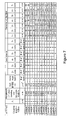
- FIG. 7 shows calculation examples 1 ⁇ 13
- FIG. 8 is a graph, which shows the relationship between wavelength ⁇ 1 and ⁇ ;
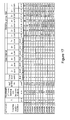
- FIG. 9 shows calculation examples 14 ⁇ 26
- FIG. 10 shows calculation examples 27 ⁇ 39
- FIG. 11 shows calculation examples 40 ⁇ 52
- FIG. 12 shows calculation examples 53 ⁇ 65
- FIG. 13 shows calculation examples 66 ⁇ 78
- FIG. 14 shows calculation examples 79 ⁇ 91
- FIG. 15 shows calculation examples 92 ⁇ 104
- FIG. 16 shows calculation examples 105 ⁇ 117
- FIG. 17 shows calculation examples 118 ⁇ 130
- FIG. 18 shows a block diagram of an optical communication system, which relates to a seventh embodiment of the present invention.
- FIG. 19 is a graph, which shows the relationship between the wavelength of a manufactured multi-core HF and transmission loss.
- FIG. 20 is a graph, which shows the relationship between the wavelength of the manufactured multi-core HF and bending loss.
- multi-core holey fiber is designated multi-core HF.
- bending loss is defined as a loss accrued when an optical fiber is wound at a diameter of 20 millimeters. The terms not especially defined herein shall follow the definitions and the measurement methods defined in the International Telecommunication Union Telecommunication Standardization Sector (ITU-T) G.650.1.
- FIG. 1 shows a schematic cross-sectional drawing of a multi-core HF related to a first embodiment of the present invention.
- the multi-core HF comprises seven cores 111 ⁇ 1117 arranged separately from each other and a cladding 12 that surrounds the cores 111 ⁇ 117 .
- the core 111 is positioned approximately at the center of the fiber and the other cores 112 ⁇ 117 are positioned at apexes of a regular hexagon with the core 111 as the center.
- the cladding 12 has a plurality of the holes 13 positioned periodically around the cores 111 ⁇ 117 .
- the holes 13 are positioned to form triangular-shaped lattices, L 1 , and to shape layers of regular hexagons to surround cores 111 ⁇ 117 .
- the cores 111 ⁇ 117 and the cladding 12 are made from pure silica glass, which does not include any refractive index control dopants.
- the diameters, d 1 , of the holes 13 are d [ ⁇ m] and a lattice constant, ⁇ 1 , of the triangular lattice, L 1 , the distance between the closest holes 13 , is ⁇ [ ⁇ m], then ⁇ is 6 ⁇ m and d/ ⁇ is 0.43.
- hole layers surrounding each of the cores 112 ⁇ 117 outward are designated as the outermost layers.
- symbol O 1 is the outermost layer.
- the outermost layers have five layers. More specifically, each of the cores 111 ⁇ 117 is surrounded by at least five hole layers. Therefore, confinement loss of each core 111 ⁇ 117 is less than 0.01 dB/km.
- core interval i.e., the distance between cores
- core interval D 1 the core interval between core 116 and core 117 is shown as core interval D 1 .
- the core interval D 1 is equivalent to eight hole layers.
- the core intervals between one of the cores 111 ⁇ 117 and adjacent cores are equivalent to eight hole layers.
- the multi-core HF 1 has ⁇ of 6 ⁇ m and d/ ⁇ of 0.43, it achieves ESM characteristics. In addition, because the multi-core HF 1 separates any of the cores 111 ⁇ 117 by core intervals of more than eight hole layers, the sum of coupling coefficients between adjacent cores is less than 1.6 ⁇ 10 ⁇ 5 /m in each of the cores 111 ⁇ 117 . As a result, when the length of the multi-core HF 1 is longer than 1 km, crosstalk of the transmitted optical signals in each of the cores 111 ⁇ 117 is suppressed to less than ⁇ 35 dB. Details are explained below.
- the crosstalk between the cores is less than ⁇ 35 dB.
- the coupling length is based on the coupling coefficient.
- the coupling coefficient can be adjusted by controlling the overlapping of optical mode fields transmitted in the cores by designing ⁇ , d/ ⁇ and the core interval of any two cores in the multi-core HF.
- the contribution of mode coupling from all other cores must be considered.
- the coupling coefficient of any of the cores from the sum of any other cores must be less than 1.6 ⁇ 10 ⁇ 5 /m. If the sum of the coupling coefficient x s is less than 1.6 ⁇ 10 ⁇ 5 /m and the effective corresponding coupling length L eff is p/(2 ⁇ s ), then the effective corresponding coupling length L eff is longer than 100 km. As a result, when the length of the multi-core HF 1 is longer than 1 km, the crosstalk of the transmitted optical signal in each of the cores 111 ⁇ 117 is suppressed to less than ⁇ 35 dB.
- the coupling coefficient decreases rapidly as core intervals between the cores increases, and therefore the sum of the coupling coefficients is approximately the same as the sum of the coupling coefficient between the closest adjacent cores.
- the sum of the coupling coefficients between the core 111 and the other cores 112 ⁇ 117 can be calculated from the sum of the coupling coefficients between the core 111 , and the other cores 112 ⁇ 117 ; and the sum of the coupling coefficients between the core 117 and the other cores 111 ⁇ 116 can be calculated from the sum of the coupling coefficients between the core 117 and other cores 111 , 112 and 116 .
- the multi-core HF 1 related to the first embodiment of the present invention suppresses the crosstalk deterioration of the optical signal transmitted in each of the cores.
- the diameter of the multi-core HF 1 is preferably set to cover 1.1 times the area needed to be covered by the holes 13 , for manufacturability.
- FIG. 2 shows a schematic cross-sectional drawing of a multi-core HF related to the second embodiment of the present invention.
- the multi-core HF 2 comprises two cores 211 , 212 arranged separately from each other and a cladding 22 positioned to surround the cores 211 , 212 .
- the cores 211 , 212 are positioned approximately symmetric to each other with respect to the center of the multi-core HF 2 .
- the cladding 22 has a plurality of holes 23 positioned periodically around the cores 211 , 212 .
- the holes 23 are positioned to form triangular lattices L 2 and to form layers of hexagons that surround the cores 211 , 212 .
- the cores 211 , 212 and the cladding 22 are made from the pure silica glass.
- the diameters, d 2 , of the holes 23 are d [ ⁇ m] and a lattice constant A 2 of the triangular lattice, L 2 , is ⁇ [ ⁇ m], then ⁇ is 6 ⁇ m and d/ ⁇ is 0.43.
- the outermost layers O 2 comprise five hole layers, which is the same for core 212 . Therefore, confinement loss of each of the cores 211 , 212 is less than 0.01 dB/km.
- the core interval, D 2 between the cores 211 and 212 has the equivalent of eight hole layers.
- FIG. 3 shows a schematic cross-sectional drawing of a multi-core HF related to the third embodiment of the present invention.
- the multi-core HF 3 comprises three cores 311 ⁇ 313 arranged separately from each other and a cladding 32 surrounds the cores 311 ⁇ 313 .
- the cores 311 ⁇ 313 are positioned at the apexes of a regular triangle, which has a center at the center of the multi-core HF 3 .
- the cladding 32 has a plurality of holes 33 positioned periodically around the cores 311 ⁇ 313 .
- the holes 33 are positioned to form triangular lattices L 3 and to form layers of hexagons that surround the cores 311 ⁇ 313 .
- the cores 311 ⁇ 313 and the cladding 32 are made from pure silica glass.
- the outermost layers O 3 comprise five hole layers, which is the same for cores 311 , 313 . Therefore, confinement loss of each of the cores 311 ⁇ 313 is less than 0.01 dB/km.
- the core interval D 2 between core 311 and core 312 is equivalent to eight hole layers, and it is the same for the core interval between core 312 and core 313 .
- the length of the multi-core HF 3 is longer than 1 km, then crosstalk of the transmitted optical signal in each of the cores 311 ⁇ 313 is suppressed to less than ⁇ 35 dB.
- FIG. 4 shows a schematic cross-sectional drawing of a multi-core HF related to the fourth embodiment of the present invention.
- the multi-core HF 4 comprises four cores 411 ⁇ 414 arranged separately from each other and a cladding 42 surrounding the cores 411 ⁇ 414 .
- the cores 411 ⁇ 414 are positioned at the apexes of a lozenge, which has a center at the center of the multi-core HF 4 .
- the cladding 42 has a plurality of holes 43 positioned periodically around the cores 411 ⁇ 414 .
- the holes 43 are positioned to form triangular lattices, L 4 , and to form layers of hexagons that surround the cores 411 ⁇ 414 .
- the cores 411 ⁇ 414 and the cladding 42 are made from pure silica glass.
- the outermost layers O 4 comprise five hole layers, which is the same for the cores 411 , 413 , 414 . Therefore, confinement loss of each cores 411 ⁇ 414 is less than 0.01 dB/km.
- the core interval, D 4 , between the core 411 and the core 412 is equivalent to eight hole layers, and it is the same for any of the core intervals between one of the cores 411 ⁇ 414 and the adjacent cores.
- the crosstalk of the transmitted optical signal in each of the cores 411 ⁇ 413 is suppressed to less than ⁇ 35 dB.
- FIG. 5 shows a schematic cross-sectional drawing of a multi-core HF related to the fifth embodiment of the present invention.
- the multi-core HF 5 comprises five cores 511 ⁇ 515 arranged separately from each other and a cladding 52 positioned surrounded the cores 511 ⁇ 515 .
- the core 511 is positioned approximately at the center of the multi-core HF 5 and each of the other cores 512 ⁇ 515 is positioned at the apexes of a regular hexagon with the core 511 centered, except the two adjacent apexes out of the five apexes as shown in FIG. 5 .
- cladding 52 has a plurality of holes 53 positioned periodically around cores 511 ⁇ 515 .
- the holes 53 are positioned to form triangular-shaped lattices, L 5 , and to form layers of hexagons that surround the cores 511 ⁇ 515 .
- the cores 511 ⁇ 515 and the cladding 52 are made from pure silica glass.
- the outermost layers O 5 comprise five hole layers, which is the same for cores 511 , 513 ⁇ 515 . Therefore, confinement loss of each of the cores 511 ⁇ 515 is less than 0.01 dB/km.
- the core interval D 5 between the core 512 and the core 513 is equivalent to eight hole layers, and it is the same for any of the core intervals between one of the cores 511 ⁇ 515 and the adjacent cores.
- the crosstalk of the transmitted optical signal in each of the cores 511 ⁇ 515 is suppressed to less than ⁇ 35 dB.
- FIG. 6 shows a schematic cross-sectional drawing of a multi-core HF related to the sixth embodiment of the present invention.
- the multi-core HF 6 comprises six cores 611 ⁇ 616 arranged separately from each other, and a cladding 62 surrounding the cores 611 ⁇ 616 .
- the cores 611 ⁇ 616 are positioned at the apexes and middle of sides of a regular triangle, which has a center at the center of the multi-core HF 6 .
- the cladding 62 has a plurality of holes 63 positioned periodically around the cores 611 ⁇ 616 .
- the holes 63 are positioned to form triangular-shaped lattices L 6 and to form layers of hexagons that surround the cores 611 ⁇ 616 .
- the cores 611 ⁇ 616 and the cladding 62 are made from pure silica glass.
- the diameters, d 6 , of the holes 63 are d [ ⁇ m] and a lattice constant, ⁇ 6 , of the triangular lattice, L 6 , is ⁇ [ ⁇ m], then ⁇ is 6 ⁇ m and d/ ⁇ is 0.43.
- the outermost layers, O 6 comprise five hole layers, which is the same for the cores 611 , 612 , 614 ⁇ 616 . Therefore, confinement loss of each of the cores 611 ⁇ 616 is less than 0.01 dB/km.
- the core interval, D 6 , between the core 612 and the core 613 is equivalent to eight hole layers, and it is the same for any of the core intervals between one of the cores 611 ⁇ 616 and the adjacent cores.
- the diameters of the multi-core HF 2 ⁇ 6 in the above second to sixth embodiments are preferably set to cover 1.1 times the area needed to be covered by the holes 13 ⁇ 63 , for manufacturability.
- the multi-core HF of the present invention is not limited to the above first to sixth embodiments, and parameters such as ⁇ , d/ ⁇ , core interval between the cores, and outermost layers can be adjusted accordingly. Below, the present invention is explained even further using calculation examples 1 ⁇ 13.
- FIG. 7 shows calculation examples 1 ⁇ 13, which calculate outermost layers of a multi-core HF having structure that is similar to the first to sixth embodiments.
- FEM Finite Element Method
- the coupling length shown in FIG. 7 in which the multi-core HF has more than three cores, means actual coupling length.
- Core interval in FIG. 7 is the core interval between cores.
- “2-core” means a multi-core HF with two cores.
- a eff @1550 nm is the effective core 1 area at the wavelength of 1550 nm.
- Fiber diameter is the diameter of each multi-core HF. The diameter of each multi-core HF is selected to cover 1.1 times the area that needs to be covered by holes based on manufacturability. Also, in FIG. 7 , as a comparison, the diameter of a single-core HF is shown as “1-core”. “Wavelength ⁇ 1 when bending loss becomes 10 dB/m” is explained latter.
- the multi-core HF related to the calculation examples has confinement loss of less than 0.01 dB/km over a coupling length of 100 km because the outermost layers and core intervals among the cores are adjusted accordingly. Also, since d/ ⁇ is 0.5, it practically achieves ESM characteristics
- This wavelength ⁇ 1 in the multi-core HF related to the calculation examples is a shortest wavelength which creates less than 10 dB/m bending loss. Therefore, the multi-core HF related to the calculation examples 1 ⁇ 13 experience 10 dB/m or greater bending loss when wavelength is shorter than the wavelength ⁇ 1 .
- conventional transmission optical fibers require the bending loss to be less than 10 dB/m, and it is preferable to use the multi-core HF related to the calculation examples 1 ⁇ 13 above the wavelength ⁇ 1 .
- FIG. 8 is a graph that shows the relationship between the wavelength ⁇ 1 and ⁇ in FIG. 7 .
- the outermost layers are calculated to make a confinement loss that is less than 0.01 dB/km; and the core intervals are also calculated to make a coupled length of 1000 km.
- the multi-core HF related to the calculation examples has a confinement loss that is less than 0.01 dB/km over a coupling length of 10000 km, and practically achieves ESM characteristics because the outermost layers and core intervals among the cores are adjusted accordingly.
- multi-core HF with a coupling length of 10000 km can keep the crosstalk between the cores within ⁇ 35 dB even if the length is set to be 100 km.
- the outermost layers are calculated to make a confinement loss that is less than 0.01 dB/km; and the core intervals are also calculated to make a coupled length of 100 km.
- the multi-core HF related to the calculation examples has a confinement loss that is less than 0.01 dB/km over a coupling length of 100 km, and practically achieves ESM characteristics because the outermost layer and core intervals among the cores are adjusted accordingly.
- the outermost layers are calculated to make a confinement loss that is less than 0.01 dB/km; and the core intervals are also calculated to make a coupled length of 10000 km.
- the multi-core HF related to the calculation examples 40 ⁇ 52 has a confinement loss that is less than 0.01 dB/km over a coupling length of 10000 km and practically achieves ESM characteristics because the outermost layers and core intervals among the cores are adjusted accordingly.
- the outermost layers are calculated to make a confinement loss that is less than 0.01 dB/km; and the core intervals are also calculated to make a coupled length of 100 km.
- the multi-core HF related to the calculation examples 53 ⁇ 65 has a confinement loss that is less than 0.01 dB/km over a coupling length of 100 km and practically achieves ESM characteristics because the outermost layers and core intervals among the cores are adjusted accordingly.
- the outermost layers are calculated to make a confinement loss that is less than 0.01 dB/km; and the core intervals are also calculated to make a coupled length of 10000 km.
- the multi-core HF related to the calculation examples 66 ⁇ 78 has a confinement loss that is less than 0.01 dB/km over coupling length of 10000 km and practically achieves ESM characteristics because the outermost layers and core intervals among the cores are adjusted accordingly.
- the outermost layers are calculated to make a confinement loss that is less than 0.01 dB/km; and the core intervals are also calculated to make a coupled length of 100 km.
- ⁇ is less than 10 ⁇ m
- bending loss at 1550 nm is less than 10 dB/m.
- the outermost layers are calculated to make a confinement loss that is less than 0.01 dB/km; and the core intervals are also calculated to make a coupled length of 10000 km.
- the multi-core HF related to the calculation examples 92 ⁇ 104 has confinement loss of less than 0.01 dB/km over a coupling length of 10000 km and practically achieves ESM characteristics because the outermost layers and core intervals among the cores are adjusted accordingly.
- the outermost layers are calculated to make a confinement loss that is less than 0.01 dB/km; and the core intervals are also calculated to make a coupled length of 100 km.
- the multi-core HF related to the calculation examples 105 ⁇ 117 has a confinement loss of less than 0.01 dB/km over a coupling length of 100 km and practically achieves ESM characteristics because the outermost layers and core intervals among the cores are adjusted accordingly.
- the outermost layers are calculated to make a confinement loss that is less than 0.01 dB/km; and the core intervals are also calculated to make a coupled length of 10000 km.
- the multi-core HF related to the calculation examples 118 ⁇ 130 has a confinement loss of less than 0.01 dB/km over a coupling length of 10000 km and practically achieves ESM characteristics because the outermost layers and core intervals among the cores are adjusted accordingly.
- the coupling length can be greater than 100 km, and if core intervals among the cores are more than seven layers, then the coupling length can be greater than 1000 km. Also, if d/ ⁇ is 0.43 and core intervals among the cores are more than seven layers, then the coupling length can be greater than 100 km, and if core intervals among the cores are more than eight layers, then the coupling length can be greater than 1000 km.
- FIG. 18 shows a block diagram of an optical communication system, which relates to the seventh embodiment.
- the optical transmission system 10 includes: an optical transmission apparatus 7 ; a multi-core HF 1 related to the first embodiment connected to the optical transmission apparatus 7 ; and an optical receiving apparatus 8 connected to the multi-core HF 1 .
- the optical transmission apparatus 7 has seven optical transmitters 71 ⁇ 77 that output optical signals at different wavelengths, and an optical multiplexer 78 that multiplexes optical signals output from the optical transmitters 71 ⁇ 77 and outputs the multiplexed signal to the multi-core HF 1 .
- the optical receiving apparatus 8 has an optical demultiplxer 88 that demultiplexes the optical signals transmitted through the multi-core HF 1 , and optical receivers 81 ⁇ 87 that receives the optical signals demultiplexed by the optical demultiplexer.
- the optical signals output from the optical transmitters 71 ⁇ 77 are, for example, laser light modulated by a Non-Return-to-Zero (NRZ) signal having a modulation rate of 10 Gbps.
- Wavelengths of the optical signals are 0.85 ⁇ m, 0.98 ⁇ m, 1.05 ⁇ m, 1.31 ⁇ m, 1.48 ⁇ m, 1.53 ⁇ m and 1.55 ⁇ m. These wavelengths are distributed in a broad wavelength bandwidth having a center thereof at approximately 1 ⁇ m. Also, those wavelengths are within the wavelength range where the multi-core HF 1 experiences less than 10 dB/m of bending loss.
- the optical multiplexer 78 multiples optical signals output from each of the optical transmitters 71 ⁇ 77 and outputs the multiplexed signal to each of the cores 111 ⁇ 117 in the multi-core HF 1 . Accordingly, each of the optical signals from the optical transmitters 71 ⁇ 77 propagate in different cores 111 ⁇ 117 from each other.
- the optical demultiplexer 88 demultiples the transmitted optical signals from the different cores 111 ⁇ 117 of the multi-core HF 1 and guides them to respective optical receivers 81 ⁇ 87 .
- the optical receivers 81 ⁇ 87 extract the NRZ signal from each of the optical signals as an electrical signal.
- the optical multiplexer 78 for example, has seven standard single-mode fibers on the input side and one multi-core HF 1 on the output side, and can be made from waveguide-type, fiber-fusion-type or space-coupling-type optical multiplexer such as an Arrayed WaveGuide (AWG). Also, the same structure element for the optical multiplexer 78 can be used for the optical demultiplexer 88 .
- AMG Arrayed WaveGuide
- the length of the multi-core HF 1 is 1 km ( 1/100 of the 100 km effective coupling length).
- multi-core HF according to the first embodiment is manufactured.
- optical characteristics about the center core (core A) and the outer cores (cores B) are measured. As a result, chromatic dispersion at 1550 nm in core A is 41.2 ps/nm/km and in cores B is 40.2 ps/nm/km.
- each of the dispersions is almost the same as the simulation result of 40.0 ps/nm/km.
- the dispersion slope at 1550 nm in core A is 0.072 ps/nm 2 /km and in cores B is 0.071 ps/nm 2 /km. Therefore, each of the dispersion slopes is almost the same as the simulation result of 0.071 ps/nm 2 /km.
- the effective core area at 1550 nm in core A is 38.7 ⁇ m 2 and in cores B is 41.8 ⁇ m 2 . Therefore, each of the effective core area is almost the same as simulation result of 35.5 ⁇ m 2 .
- FIG. 19 shows the relationship between wavelength of manufactured multi-core HF and transmission loss.
- the transmission loss at 1550 nm in core A is 2.4 dB/km and in cores B is 2.4 dB/km; at 1310 nm the transmission loss in core A is 11.5 dB/km and in cores B is 10.3 dB/km; at 1050 nm the transmission loss in core A is 2.1 dB/km and in cores B is 2.0 dB/km; and at 850 nm the transmission loss in core A is 3.6 dB/km and in cores B is 3.7 dB/km.
- FIG. 19 the transmission loss at 1550 nm in core A is 2.4 dB/km and in cores B is 2.4 dB/km; at 1310 nm the transmission loss in core A is 11.5 dB/km and in cores B is 10.3 dB/km; at 1050 nm the
- the bending loss associated with a 20 mm diameter bend in the wavelength region longer than 500 nm in both core A and cores B is relatively low (i.e., less than 2 dB/m).
- the crosstalk at wavelengths of 850 nm, 1050 nm, 1310 nm and 1550 nm is relatively small (i.e., less than 60 dB).
Abstract
Description
Claims (8)
Λ=−0.14901λs 2+9.3134λs+1.3171.
Applications Claiming Priority (2)
| Application Number | Priority Date | Filing Date | Title |
|---|---|---|---|
| JP2008-222806 | 2008-08-29 | ||
| JP2008222806A JP5415728B2 (en) | 2008-08-29 | 2008-08-29 | Multi-core holey fiber and optical transmission system |
Publications (2)
| Publication Number | Publication Date |
|---|---|
| US20100054742A1 US20100054742A1 (en) | 2010-03-04 |
| US8094985B2 true US8094985B2 (en) | 2012-01-10 |
Family
ID=41725606
Family Applications (1)
| Application Number | Title | Priority Date | Filing Date |
|---|---|---|---|
| US12/546,894 Expired - Fee Related US8094985B2 (en) | 2008-08-29 | 2009-08-25 | Multi-core holey fiber and optical transmission system |
Country Status (2)
| Country | Link |
|---|---|
| US (1) | US8094985B2 (en) |
| JP (1) | JP5415728B2 (en) |
Cited By (169)
| Publication number | Priority date | Publication date | Assignee | Title |
|---|---|---|---|---|
| US8737793B2 (en) | 2010-03-16 | 2014-05-27 | Furukawa Electric Co., Ltd. | Multi-core optical fiber and method of manufacturing the same |
| US20150078744A1 (en) * | 2012-04-20 | 2015-03-19 | Nec Corporation | Multiplexed optical transmission line, optical transmission system, and optical transmission method |
| US9119127B1 (en) | 2012-12-05 | 2015-08-25 | At&T Intellectual Property I, Lp | Backhaul link for distributed antenna system |
| US9154966B2 (en) | 2013-11-06 | 2015-10-06 | At&T Intellectual Property I, Lp | Surface-wave communications and methods thereof |
| US9209902B2 (en) | 2013-12-10 | 2015-12-08 | At&T Intellectual Property I, L.P. | Quasi-optical coupler |
| US9312919B1 (en) | 2014-10-21 | 2016-04-12 | At&T Intellectual Property I, Lp | Transmission device with impairment compensation and methods for use therewith |
| US9461706B1 (en) | 2015-07-31 | 2016-10-04 | At&T Intellectual Property I, Lp | Method and apparatus for exchanging communication signals |
| US9490869B1 (en) | 2015-05-14 | 2016-11-08 | At&T Intellectual Property I, L.P. | Transmission medium having multiple cores and methods for use therewith |
| US9503189B2 (en) | 2014-10-10 | 2016-11-22 | At&T Intellectual Property I, L.P. | Method and apparatus for arranging communication sessions in a communication system |
| US9509415B1 (en) | 2015-06-25 | 2016-11-29 | At&T Intellectual Property I, L.P. | Methods and apparatus for inducing a fundamental wave mode on a transmission medium |
| US9520945B2 (en) | 2014-10-21 | 2016-12-13 | At&T Intellectual Property I, L.P. | Apparatus for providing communication services and methods thereof |
| US9525524B2 (en) | 2013-05-31 | 2016-12-20 | At&T Intellectual Property I, L.P. | Remote distributed antenna system |
| US9525210B2 (en) | 2014-10-21 | 2016-12-20 | At&T Intellectual Property I, L.P. | Guided-wave transmission device with non-fundamental mode propagation and methods for use therewith |
| US9531427B2 (en) | 2014-11-20 | 2016-12-27 | At&T Intellectual Property I, L.P. | Transmission device with mode division multiplexing and methods for use therewith |
| US9564947B2 (en) | 2014-10-21 | 2017-02-07 | At&T Intellectual Property I, L.P. | Guided-wave transmission device with diversity and methods for use therewith |
| US9577307B2 (en) | 2014-10-21 | 2017-02-21 | At&T Intellectual Property I, L.P. | Guided-wave transmission device and methods for use therewith |
| US9608740B2 (en) | 2015-07-15 | 2017-03-28 | At&T Intellectual Property I, L.P. | Method and apparatus for launching a wave mode that mitigates interference |
| US9608692B2 (en) | 2015-06-11 | 2017-03-28 | At&T Intellectual Property I, L.P. | Repeater and methods for use therewith |
| US9615269B2 (en) | 2014-10-02 | 2017-04-04 | At&T Intellectual Property I, L.P. | Method and apparatus that provides fault tolerance in a communication network |
| US9628854B2 (en) | 2014-09-29 | 2017-04-18 | At&T Intellectual Property I, L.P. | Method and apparatus for distributing content in a communication network |
| US9628116B2 (en) | 2015-07-14 | 2017-04-18 | At&T Intellectual Property I, L.P. | Apparatus and methods for transmitting wireless signals |
| US9640850B2 (en) | 2015-06-25 | 2017-05-02 | At&T Intellectual Property I, L.P. | Methods and apparatus for inducing a non-fundamental wave mode on a transmission medium |
| US9653770B2 (en) | 2014-10-21 | 2017-05-16 | At&T Intellectual Property I, L.P. | Guided wave coupler, coupling module and methods for use therewith |
| US9667317B2 (en) | 2015-06-15 | 2017-05-30 | At&T Intellectual Property I, L.P. | Method and apparatus for providing security using network traffic adjustments |
| US9680670B2 (en) | 2014-11-20 | 2017-06-13 | At&T Intellectual Property I, L.P. | Transmission device with channel equalization and control and methods for use therewith |
| US9685992B2 (en) | 2014-10-03 | 2017-06-20 | At&T Intellectual Property I, L.P. | Circuit panel network and methods thereof |
| US9692101B2 (en) | 2014-08-26 | 2017-06-27 | At&T Intellectual Property I, L.P. | Guided wave couplers for coupling electromagnetic waves between a waveguide surface and a surface of a wire |
| US9705571B2 (en) | 2015-09-16 | 2017-07-11 | At&T Intellectual Property I, L.P. | Method and apparatus for use with a radio distributed antenna system |
| US9705561B2 (en) | 2015-04-24 | 2017-07-11 | At&T Intellectual Property I, L.P. | Directional coupling device and methods for use therewith |
| US9722318B2 (en) | 2015-07-14 | 2017-08-01 | At&T Intellectual Property I, L.P. | Method and apparatus for coupling an antenna to a device |
| US9729197B2 (en) | 2015-10-01 | 2017-08-08 | At&T Intellectual Property I, L.P. | Method and apparatus for communicating network management traffic over a network |
| US9735833B2 (en) | 2015-07-31 | 2017-08-15 | At&T Intellectual Property I, L.P. | Method and apparatus for communications management in a neighborhood network |
| US9742462B2 (en) | 2014-12-04 | 2017-08-22 | At&T Intellectual Property I, L.P. | Transmission medium and communication interfaces and methods for use therewith |
| US9748626B2 (en) | 2015-05-14 | 2017-08-29 | At&T Intellectual Property I, L.P. | Plurality of cables having different cross-sectional shapes which are bundled together to form a transmission medium |
| US9749013B2 (en) | 2015-03-17 | 2017-08-29 | At&T Intellectual Property I, L.P. | Method and apparatus for reducing attenuation of electromagnetic waves guided by a transmission medium |
| US9749053B2 (en) | 2015-07-23 | 2017-08-29 | At&T Intellectual Property I, L.P. | Node device, repeater and methods for use therewith |
| US9755697B2 (en) | 2014-09-15 | 2017-09-05 | At&T Intellectual Property I, L.P. | Method and apparatus for sensing a condition in a transmission medium of electromagnetic waves |
| US9762289B2 (en) | 2014-10-14 | 2017-09-12 | At&T Intellectual Property I, L.P. | Method and apparatus for transmitting or receiving signals in a transportation system |
| US9769128B2 (en) | 2015-09-28 | 2017-09-19 | At&T Intellectual Property I, L.P. | Method and apparatus for encryption of communications over a network |
| US9769020B2 (en) | 2014-10-21 | 2017-09-19 | At&T Intellectual Property I, L.P. | Method and apparatus for responding to events affecting communications in a communication network |
| US9780834B2 (en) | 2014-10-21 | 2017-10-03 | At&T Intellectual Property I, L.P. | Method and apparatus for transmitting electromagnetic waves |
| US9793955B2 (en) | 2015-04-24 | 2017-10-17 | At&T Intellectual Property I, Lp | Passive electrical coupling device and methods for use therewith |
| US9793954B2 (en) | 2015-04-28 | 2017-10-17 | At&T Intellectual Property I, L.P. | Magnetic coupling device and methods for use therewith |
| US9793951B2 (en) | 2015-07-15 | 2017-10-17 | At&T Intellectual Property I, L.P. | Method and apparatus for launching a wave mode that mitigates interference |
| US9800327B2 (en) | 2014-11-20 | 2017-10-24 | At&T Intellectual Property I, L.P. | Apparatus for controlling operations of a communication device and methods thereof |
| US9820146B2 (en) | 2015-06-12 | 2017-11-14 | At&T Intellectual Property I, L.P. | Method and apparatus for authentication and identity management of communicating devices |
| US9838896B1 (en) | 2016-12-09 | 2017-12-05 | At&T Intellectual Property I, L.P. | Method and apparatus for assessing network coverage |
| US9836957B2 (en) | 2015-07-14 | 2017-12-05 | At&T Intellectual Property I, L.P. | Method and apparatus for communicating with premises equipment |
| US9847566B2 (en) | 2015-07-14 | 2017-12-19 | At&T Intellectual Property I, L.P. | Method and apparatus for adjusting a field of a signal to mitigate interference |
| US9847850B2 (en) | 2014-10-14 | 2017-12-19 | At&T Intellectual Property I, L.P. | Method and apparatus for adjusting a mode of communication in a communication network |
| US9853342B2 (en) | 2015-07-14 | 2017-12-26 | At&T Intellectual Property I, L.P. | Dielectric transmission medium connector and methods for use therewith |
| US9860075B1 (en) | 2016-08-26 | 2018-01-02 | At&T Intellectual Property I, L.P. | Method and communication node for broadband distribution |
| US9865911B2 (en) | 2015-06-25 | 2018-01-09 | At&T Intellectual Property I, L.P. | Waveguide system for slot radiating first electromagnetic waves that are combined into a non-fundamental wave mode second electromagnetic wave on a transmission medium |
| US9866309B2 (en) | 2015-06-03 | 2018-01-09 | At&T Intellectual Property I, Lp | Host node device and methods for use therewith |
| US9871282B2 (en) | 2015-05-14 | 2018-01-16 | At&T Intellectual Property I, L.P. | At least one transmission medium having a dielectric surface that is covered at least in part by a second dielectric |
| US9871283B2 (en) | 2015-07-23 | 2018-01-16 | At&T Intellectual Property I, Lp | Transmission medium having a dielectric core comprised of plural members connected by a ball and socket configuration |
| US9876605B1 (en) | 2016-10-21 | 2018-01-23 | At&T Intellectual Property I, L.P. | Launcher and coupling system to support desired guided wave mode |
| US9876264B2 (en) | 2015-10-02 | 2018-01-23 | At&T Intellectual Property I, Lp | Communication system, guided wave switch and methods for use therewith |
| US9876570B2 (en) | 2015-02-20 | 2018-01-23 | At&T Intellectual Property I, Lp | Guided-wave transmission device with non-fundamental mode propagation and methods for use therewith |
| US9882257B2 (en) | 2015-07-14 | 2018-01-30 | At&T Intellectual Property I, L.P. | Method and apparatus for launching a wave mode that mitigates interference |
| US9882277B2 (en) | 2015-10-02 | 2018-01-30 | At&T Intellectual Property I, Lp | Communication device and antenna assembly with actuated gimbal mount |
| US9893795B1 (en) | 2016-12-07 | 2018-02-13 | At&T Intellectual Property I, Lp | Method and repeater for broadband distribution |
| US9904535B2 (en) | 2015-09-14 | 2018-02-27 | At&T Intellectual Property I, L.P. | Method and apparatus for distributing software |
| US9906269B2 (en) | 2014-09-17 | 2018-02-27 | At&T Intellectual Property I, L.P. | Monitoring and mitigating conditions in a communication network |
| US9911020B1 (en) | 2016-12-08 | 2018-03-06 | At&T Intellectual Property I, L.P. | Method and apparatus for tracking via a radio frequency identification device |
| US9912419B1 (en) | 2016-08-24 | 2018-03-06 | At&T Intellectual Property I, L.P. | Method and apparatus for managing a fault in a distributed antenna system |
| US9912381B2 (en) | 2015-06-03 | 2018-03-06 | At&T Intellectual Property I, Lp | Network termination and methods for use therewith |
| US9913139B2 (en) | 2015-06-09 | 2018-03-06 | At&T Intellectual Property I, L.P. | Signal fingerprinting for authentication of communicating devices |
| US9912027B2 (en) | 2015-07-23 | 2018-03-06 | At&T Intellectual Property I, L.P. | Method and apparatus for exchanging communication signals |
| US9917341B2 (en) | 2015-05-27 | 2018-03-13 | At&T Intellectual Property I, L.P. | Apparatus and method for launching electromagnetic waves and for modifying radial dimensions of the propagating electromagnetic waves |
| US9927517B1 (en) | 2016-12-06 | 2018-03-27 | At&T Intellectual Property I, L.P. | Apparatus and methods for sensing rainfall |
| US9948333B2 (en) | 2015-07-23 | 2018-04-17 | At&T Intellectual Property I, L.P. | Method and apparatus for wireless communications to mitigate interference |
| US9948354B2 (en) | 2015-04-28 | 2018-04-17 | At&T Intellectual Property I, L.P. | Magnetic coupling device with reflective plate and methods for use therewith |
| US9954287B2 (en) | 2014-11-20 | 2018-04-24 | At&T Intellectual Property I, L.P. | Apparatus for converting wireless signals and electromagnetic waves and methods thereof |
| US9967173B2 (en) | 2015-07-31 | 2018-05-08 | At&T Intellectual Property I, L.P. | Method and apparatus for authentication and identity management of communicating devices |
| US9973940B1 (en) | 2017-02-27 | 2018-05-15 | At&T Intellectual Property I, L.P. | Apparatus and methods for dynamic impedance matching of a guided wave launcher |
| US9991580B2 (en) | 2016-10-21 | 2018-06-05 | At&T Intellectual Property I, L.P. | Launcher and coupling system for guided wave mode cancellation |
| US9997819B2 (en) | 2015-06-09 | 2018-06-12 | At&T Intellectual Property I, L.P. | Transmission medium and method for facilitating propagation of electromagnetic waves via a core |
| US9999038B2 (en) | 2013-05-31 | 2018-06-12 | At&T Intellectual Property I, L.P. | Remote distributed antenna system |
| US9998870B1 (en) | 2016-12-08 | 2018-06-12 | At&T Intellectual Property I, L.P. | Method and apparatus for proximity sensing |
| US10009901B2 (en) | 2015-09-16 | 2018-06-26 | At&T Intellectual Property I, L.P. | Method, apparatus, and computer-readable storage medium for managing utilization of wireless resources between base stations |
| US10009065B2 (en) | 2012-12-05 | 2018-06-26 | At&T Intellectual Property I, L.P. | Backhaul link for distributed antenna system |
| US10009067B2 (en) | 2014-12-04 | 2018-06-26 | At&T Intellectual Property I, L.P. | Method and apparatus for configuring a communication interface |
| US10009063B2 (en) | 2015-09-16 | 2018-06-26 | At&T Intellectual Property I, L.P. | Method and apparatus for use with a radio distributed antenna system having an out-of-band reference signal |
| US10020844B2 (en) | 2016-12-06 | 2018-07-10 | T&T Intellectual Property I, L.P. | Method and apparatus for broadcast communication via guided waves |
| US10020587B2 (en) | 2015-07-31 | 2018-07-10 | At&T Intellectual Property I, L.P. | Radial antenna and methods for use therewith |
| US10027397B2 (en) | 2016-12-07 | 2018-07-17 | At&T Intellectual Property I, L.P. | Distributed antenna system and methods for use therewith |
| US10033108B2 (en) | 2015-07-14 | 2018-07-24 | At&T Intellectual Property I, L.P. | Apparatus and methods for generating an electromagnetic wave having a wave mode that mitigates interference |
| US10033107B2 (en) | 2015-07-14 | 2018-07-24 | At&T Intellectual Property I, L.P. | Method and apparatus for coupling an antenna to a device |
| US10044409B2 (en) | 2015-07-14 | 2018-08-07 | At&T Intellectual Property I, L.P. | Transmission medium and methods for use therewith |
| US10051629B2 (en) | 2015-09-16 | 2018-08-14 | At&T Intellectual Property I, L.P. | Method and apparatus for use with a radio distributed antenna system having an in-band reference signal |
| US10051483B2 (en) | 2015-10-16 | 2018-08-14 | At&T Intellectual Property I, L.P. | Method and apparatus for directing wireless signals |
| US10069535B2 (en) | 2016-12-08 | 2018-09-04 | At&T Intellectual Property I, L.P. | Apparatus and methods for launching electromagnetic waves having a certain electric field structure |
| US10074890B2 (en) | 2015-10-02 | 2018-09-11 | At&T Intellectual Property I, L.P. | Communication device and antenna with integrated light assembly |
| US10079661B2 (en) | 2015-09-16 | 2018-09-18 | At&T Intellectual Property I, L.P. | Method and apparatus for use with a radio distributed antenna system having a clock reference |
| US10090594B2 (en) | 2016-11-23 | 2018-10-02 | At&T Intellectual Property I, L.P. | Antenna system having structural configurations for assembly |
| US10090606B2 (en) | 2015-07-15 | 2018-10-02 | At&T Intellectual Property I, L.P. | Antenna system with dielectric array and methods for use therewith |
| US10103801B2 (en) | 2015-06-03 | 2018-10-16 | At&T Intellectual Property I, L.P. | Host node device and methods for use therewith |
| US10103422B2 (en) | 2016-12-08 | 2018-10-16 | At&T Intellectual Property I, L.P. | Method and apparatus for mounting network devices |
| US10136434B2 (en) | 2015-09-16 | 2018-11-20 | At&T Intellectual Property I, L.P. | Method and apparatus for use with a radio distributed antenna system having an ultra-wideband control channel |
| US10135146B2 (en) | 2016-10-18 | 2018-11-20 | At&T Intellectual Property I, L.P. | Apparatus and methods for launching guided waves via circuits |
| US10135145B2 (en) | 2016-12-06 | 2018-11-20 | At&T Intellectual Property I, L.P. | Apparatus and methods for generating an electromagnetic wave along a transmission medium |
| US10135147B2 (en) | 2016-10-18 | 2018-11-20 | At&T Intellectual Property I, L.P. | Apparatus and methods for launching guided waves via an antenna |
| US10142086B2 (en) | 2015-06-11 | 2018-11-27 | At&T Intellectual Property I, L.P. | Repeater and methods for use therewith |
| US10139820B2 (en) | 2016-12-07 | 2018-11-27 | At&T Intellectual Property I, L.P. | Method and apparatus for deploying equipment of a communication system |
| US10148016B2 (en) | 2015-07-14 | 2018-12-04 | At&T Intellectual Property I, L.P. | Apparatus and methods for communicating utilizing an antenna array |
| US10144036B2 (en) | 2015-01-30 | 2018-12-04 | At&T Intellectual Property I, L.P. | Method and apparatus for mitigating interference affecting a propagation of electromagnetic waves guided by a transmission medium |
| US10154493B2 (en) | 2015-06-03 | 2018-12-11 | At&T Intellectual Property I, L.P. | Network termination and methods for use therewith |
| US10170840B2 (en) | 2015-07-14 | 2019-01-01 | At&T Intellectual Property I, L.P. | Apparatus and methods for sending or receiving electromagnetic signals |
| US10168695B2 (en) | 2016-12-07 | 2019-01-01 | At&T Intellectual Property I, L.P. | Method and apparatus for controlling an unmanned aircraft |
| US10178445B2 (en) | 2016-11-23 | 2019-01-08 | At&T Intellectual Property I, L.P. | Methods, devices, and systems for load balancing between a plurality of waveguides |
| US10205655B2 (en) | 2015-07-14 | 2019-02-12 | At&T Intellectual Property I, L.P. | Apparatus and methods for communicating utilizing an antenna array and multiple communication paths |
| US10224634B2 (en) | 2016-11-03 | 2019-03-05 | At&T Intellectual Property I, L.P. | Methods and apparatus for adjusting an operational characteristic of an antenna |
| US10225025B2 (en) | 2016-11-03 | 2019-03-05 | At&T Intellectual Property I, L.P. | Method and apparatus for detecting a fault in a communication system |
| US10243784B2 (en) | 2014-11-20 | 2019-03-26 | At&T Intellectual Property I, L.P. | System for generating topology information and methods thereof |
| US10243270B2 (en) | 2016-12-07 | 2019-03-26 | At&T Intellectual Property I, L.P. | Beam adaptive multi-feed dielectric antenna system and methods for use therewith |
| US10264586B2 (en) | 2016-12-09 | 2019-04-16 | At&T Mobility Ii Llc | Cloud-based packet controller and methods for use therewith |
| US10291311B2 (en) | 2016-09-09 | 2019-05-14 | At&T Intellectual Property I, L.P. | Method and apparatus for mitigating a fault in a distributed antenna system |
| US10291334B2 (en) | 2016-11-03 | 2019-05-14 | At&T Intellectual Property I, L.P. | System for detecting a fault in a communication system |
| US10298293B2 (en) | 2017-03-13 | 2019-05-21 | At&T Intellectual Property I, L.P. | Apparatus of communication utilizing wireless network devices |
| US10305190B2 (en) | 2016-12-01 | 2019-05-28 | At&T Intellectual Property I, L.P. | Reflecting dielectric antenna system and methods for use therewith |
| US10312567B2 (en) | 2016-10-26 | 2019-06-04 | At&T Intellectual Property I, L.P. | Launcher with planar strip antenna and methods for use therewith |
| US10320586B2 (en) | 2015-07-14 | 2019-06-11 | At&T Intellectual Property I, L.P. | Apparatus and methods for generating non-interfering electromagnetic waves on an insulated transmission medium |
| US10326494B2 (en) | 2016-12-06 | 2019-06-18 | At&T Intellectual Property I, L.P. | Apparatus for measurement de-embedding and methods for use therewith |
| US10326689B2 (en) | 2016-12-08 | 2019-06-18 | At&T Intellectual Property I, L.P. | Method and system for providing alternative communication paths |
| US10340600B2 (en) | 2016-10-18 | 2019-07-02 | At&T Intellectual Property I, L.P. | Apparatus and methods for launching guided waves via plural waveguide systems |
| US10340573B2 (en) | 2016-10-26 | 2019-07-02 | At&T Intellectual Property I, L.P. | Launcher with cylindrical coupling device and methods for use therewith |
| US10340603B2 (en) | 2016-11-23 | 2019-07-02 | At&T Intellectual Property I, L.P. | Antenna system having shielded structural configurations for assembly |
| US10340983B2 (en) | 2016-12-09 | 2019-07-02 | At&T Intellectual Property I, L.P. | Method and apparatus for surveying remote sites via guided wave communications |
| US10341142B2 (en) | 2015-07-14 | 2019-07-02 | At&T Intellectual Property I, L.P. | Apparatus and methods for generating non-interfering electromagnetic waves on an uninsulated conductor |
| US10340601B2 (en) | 2016-11-23 | 2019-07-02 | At&T Intellectual Property I, L.P. | Multi-antenna system and methods for use therewith |
| US10348391B2 (en) | 2015-06-03 | 2019-07-09 | At&T Intellectual Property I, L.P. | Client node device with frequency conversion and methods for use therewith |
| US10355367B2 (en) | 2015-10-16 | 2019-07-16 | At&T Intellectual Property I, L.P. | Antenna structure for exchanging wireless signals |
| US10361489B2 (en) | 2016-12-01 | 2019-07-23 | At&T Intellectual Property I, L.P. | Dielectric dish antenna system and methods for use therewith |
| US10359749B2 (en) | 2016-12-07 | 2019-07-23 | At&T Intellectual Property I, L.P. | Method and apparatus for utilities management via guided wave communication |
| US10374316B2 (en) | 2016-10-21 | 2019-08-06 | At&T Intellectual Property I, L.P. | System and dielectric antenna with non-uniform dielectric |
| US10382976B2 (en) | 2016-12-06 | 2019-08-13 | At&T Intellectual Property I, L.P. | Method and apparatus for managing wireless communications based on communication paths and network device positions |
| US10389037B2 (en) | 2016-12-08 | 2019-08-20 | At&T Intellectual Property I, L.P. | Apparatus and methods for selecting sections of an antenna array and use therewith |
| US10389029B2 (en) | 2016-12-07 | 2019-08-20 | At&T Intellectual Property I, L.P. | Multi-feed dielectric antenna system with core selection and methods for use therewith |
| US10396887B2 (en) | 2015-06-03 | 2019-08-27 | At&T Intellectual Property I, L.P. | Client node device and methods for use therewith |
| US10411920B2 (en) | 2014-11-20 | 2019-09-10 | At&T Intellectual Property I, L.P. | Methods and apparatus for inducing electromagnetic waves within pathways of a cable |
| US10411356B2 (en) | 2016-12-08 | 2019-09-10 | At&T Intellectual Property I, L.P. | Apparatus and methods for selectively targeting communication devices with an antenna array |
| US10439675B2 (en) | 2016-12-06 | 2019-10-08 | At&T Intellectual Property I, L.P. | Method and apparatus for repeating guided wave communication signals |
| US10446936B2 (en) | 2016-12-07 | 2019-10-15 | At&T Intellectual Property I, L.P. | Multi-feed dielectric antenna system and methods for use therewith |
| US10498044B2 (en) | 2016-11-03 | 2019-12-03 | At&T Intellectual Property I, L.P. | Apparatus for configuring a surface of an antenna |
| US10505252B2 (en) | 2014-11-20 | 2019-12-10 | At&T Intellectual Property I, L.P. | Communication system having a coupler for guiding electromagnetic waves through interstitial areas formed by a plurality of stranded uninsulated conductors and method of use |
| US10505249B2 (en) | 2014-11-20 | 2019-12-10 | At&T Intellectual Property I, L.P. | Communication system having a cable with a plurality of stranded uninsulated conductors forming interstitial areas for guiding electromagnetic waves therein and method of use |
| US10505250B2 (en) | 2014-11-20 | 2019-12-10 | At&T Intellectual Property I, L.P. | Communication system having a cable with a plurality of stranded uninsulated conductors forming interstitial areas for propagating guided wave modes therein and methods of use |
| US10505248B2 (en) | 2014-11-20 | 2019-12-10 | At&T Intellectual Property I, L.P. | Communication cable having a plurality of uninsulated conductors forming interstitial areas for propagating electromagnetic waves therein and method of use |
| US10516555B2 (en) | 2014-11-20 | 2019-12-24 | At&T Intellectual Property I, L.P. | Methods and apparatus for creating interstitial areas in a cable |
| US10530505B2 (en) | 2016-12-08 | 2020-01-07 | At&T Intellectual Property I, L.P. | Apparatus and methods for launching electromagnetic waves along a transmission medium |
| US10535928B2 (en) | 2016-11-23 | 2020-01-14 | At&T Intellectual Property I, L.P. | Antenna system and methods for use therewith |
| US10547348B2 (en) | 2016-12-07 | 2020-01-28 | At&T Intellectual Property I, L.P. | Method and apparatus for switching transmission mediums in a communication system |
| US10554454B2 (en) | 2014-11-20 | 2020-02-04 | At&T Intellectual Property I, L.P. | Methods and apparatus for inducing electromagnetic waves in a cable |
| US10601494B2 (en) | 2016-12-08 | 2020-03-24 | At&T Intellectual Property I, L.P. | Dual-band communication device and method for use therewith |
| US10637149B2 (en) | 2016-12-06 | 2020-04-28 | At&T Intellectual Property I, L.P. | Injection molded dielectric antenna and methods for use therewith |
| US10665942B2 (en) | 2015-10-16 | 2020-05-26 | At&T Intellectual Property I, L.P. | Method and apparatus for adjusting wireless communications |
| US10679767B2 (en) | 2015-05-15 | 2020-06-09 | At&T Intellectual Property I, L.P. | Transmission medium having a conductive material and methods for use therewith |
| US10694379B2 (en) | 2016-12-06 | 2020-06-23 | At&T Intellectual Property I, L.P. | Waveguide system with device-based authentication and methods for use therewith |
| US10727599B2 (en) | 2016-12-06 | 2020-07-28 | At&T Intellectual Property I, L.P. | Launcher with slot antenna and methods for use therewith |
| US10755542B2 (en) | 2016-12-06 | 2020-08-25 | At&T Intellectual Property I, L.P. | Method and apparatus for surveillance via guided wave communication |
| US10777873B2 (en) | 2016-12-08 | 2020-09-15 | At&T Intellectual Property I, L.P. | Method and apparatus for mounting network devices |
| US10784670B2 (en) | 2015-07-23 | 2020-09-22 | At&T Intellectual Property I, L.P. | Antenna support for aligning an antenna |
| US10811767B2 (en) | 2016-10-21 | 2020-10-20 | At&T Intellectual Property I, L.P. | System and dielectric antenna with convex dielectric radome |
| US10819035B2 (en) | 2016-12-06 | 2020-10-27 | At&T Intellectual Property I, L.P. | Launcher with helical antenna and methods for use therewith |
| US10916969B2 (en) | 2016-12-08 | 2021-02-09 | At&T Intellectual Property I, L.P. | Method and apparatus for providing power using an inductive coupling |
| US10938108B2 (en) | 2016-12-08 | 2021-03-02 | At&T Intellectual Property I, L.P. | Frequency selective multi-feed dielectric antenna system and methods for use therewith |
| US11025460B2 (en) | 2014-11-20 | 2021-06-01 | At&T Intellectual Property I, L.P. | Methods and apparatus for accessing interstitial areas of a cable |
| US11032819B2 (en) | 2016-09-15 | 2021-06-08 | At&T Intellectual Property I, L.P. | Method and apparatus for use with a radio distributed antenna system having a control channel reference signal |
Families Citing this family (15)
| Publication number | Priority date | Publication date | Assignee | Title |
|---|---|---|---|---|
| JP5367726B2 (en) | 2008-12-24 | 2013-12-11 | 古河電気工業株式会社 | Multi-core optical fiber |
| JP5224371B2 (en) * | 2008-12-25 | 2013-07-03 | 古河電気工業株式会社 | Multi-core optical fiber |
| WO2010119930A1 (en) * | 2009-04-16 | 2010-10-21 | 古河電気工業株式会社 | Multi-core optical fiber |
| KR101626265B1 (en) * | 2009-04-27 | 2016-05-31 | 피코메트릭스 엘엘씨 | System and method reducing fiber stretch induced timing errors in fiber optic coupled time domain terahertz systems |
| WO2011112846A1 (en) * | 2010-03-10 | 2011-09-15 | Ofs Fitel Llc. A Delaware Limited Liability Company | Multicore fibers and associated structures and techniques |
| US8503845B2 (en) * | 2011-01-17 | 2013-08-06 | Alcatel Lucent | Multi-core optical fiber and optical communication systems |
| WO2013033703A1 (en) * | 2011-09-02 | 2013-03-07 | Alcatel-Lucent Usa Inc. | Method and apparatus for space-division multiplexing systems |
| US8811784B2 (en) * | 2011-10-04 | 2014-08-19 | Furukawa Electric Co., Ltd. | Optical fiber and optical transmission system |
| WO2013051295A1 (en) * | 2011-10-04 | 2013-04-11 | 古河電気工業株式会社 | Optical fiber and optical transmission system |
| US8811787B2 (en) | 2011-11-30 | 2014-08-19 | At&T Intellectual Property I, L.P. | Multicore optical fiber with reduced inter-core crosstalk |
| CN103325898B (en) * | 2012-03-23 | 2015-11-04 | 南京理工大学 | 1.3 mum wavelengths without polarization high efficiency light-emitting quantum dot device and method for designing |
| GB2526879A (en) * | 2014-06-06 | 2015-12-09 | Univ Southampton | Hollow-core optical fibers |
| CN106575014B (en) | 2014-08-22 | 2019-12-17 | 住友电气工业株式会社 | Optical fiber |
| JP6063007B2 (en) * | 2015-07-03 | 2017-01-18 | 日本電信電話株式会社 | Optical transmission system and optical transmission method |
| US11163109B2 (en) * | 2017-07-13 | 2021-11-02 | Nanyang Technological University | Fiber preform, optical fiber, methods for forming the same, and optical devices having the optical fiber |
Citations (12)
| Publication number | Priority date | Publication date | Assignee | Title |
|---|---|---|---|---|
| WO2006100488A1 (en) | 2005-03-24 | 2006-09-28 | Qinetiq Limited | Multiple core microstructured optical fibre |
| US20080219667A1 (en) | 2006-10-16 | 2008-09-11 | The Furukawa Electric Co, Ltd. | Optical communication system and dispersion-compensating optical fiber |
| US20080310807A1 (en) | 2007-03-12 | 2008-12-18 | The Furukawa Electric Co., Ltd. | Optical fiber and optical-fiber transmission line |
| US20090080845A1 (en) | 2007-09-26 | 2009-03-26 | Furukawa Electric Co., Ltd. | Photonic bandgap fiber |
| US20090097810A1 (en) | 2007-10-11 | 2009-04-16 | The Furukawa Electric Co., Ltd. | Holey fiber |
| US20090148112A1 (en) | 2006-06-30 | 2009-06-11 | The Furukawa Electric Co., Ltd. | Optical fiber |
| US7609928B2 (en) | 2007-08-27 | 2009-10-27 | The Furukawa Electric Co., Ltd. | Method of connecting optical fibers |
| US7613374B2 (en) | 2006-10-04 | 2009-11-03 | The Furukawa Electric Co., Ltd. | Optical fiber and optical-fiber transmission line |
| US20090324242A1 (en) * | 2008-02-27 | 2009-12-31 | Furukawa Electric Co., Ltd. | Optical transmission system and multi-core optical fiber |
| US20100290750A1 (en) * | 2008-12-25 | 2010-11-18 | Furukawa Electric Co., Ltd. | Multi-core optical fiber |
| US20100296784A1 (en) * | 2008-12-24 | 2010-11-25 | Furukawa Electric Co., Ltd. | Multi-core optical fiber |
| US20110176776A1 (en) * | 2010-01-15 | 2011-07-21 | Furukawa Electric Co., Ltd. | Multi-core optical fiber, optical connector and method of manufacturing multi-core optical fiber |
-
2008
- 2008-08-29 JP JP2008222806A patent/JP5415728B2/en not_active Expired - Fee Related
-
2009
- 2009-08-25 US US12/546,894 patent/US8094985B2/en not_active Expired - Fee Related
Patent Citations (14)
| Publication number | Priority date | Publication date | Assignee | Title |
|---|---|---|---|---|
| WO2006100488A1 (en) | 2005-03-24 | 2006-09-28 | Qinetiq Limited | Multiple core microstructured optical fibre |
| US20090148112A1 (en) | 2006-06-30 | 2009-06-11 | The Furukawa Electric Co., Ltd. | Optical fiber |
| US7613374B2 (en) | 2006-10-04 | 2009-11-03 | The Furukawa Electric Co., Ltd. | Optical fiber and optical-fiber transmission line |
| US20080219667A1 (en) | 2006-10-16 | 2008-09-11 | The Furukawa Electric Co, Ltd. | Optical communication system and dispersion-compensating optical fiber |
| US20080310807A1 (en) | 2007-03-12 | 2008-12-18 | The Furukawa Electric Co., Ltd. | Optical fiber and optical-fiber transmission line |
| US7609928B2 (en) | 2007-08-27 | 2009-10-27 | The Furukawa Electric Co., Ltd. | Method of connecting optical fibers |
| US20090080845A1 (en) | 2007-09-26 | 2009-03-26 | Furukawa Electric Co., Ltd. | Photonic bandgap fiber |
| US7657141B2 (en) * | 2007-09-26 | 2010-02-02 | The Furukawa Electric Co., Ltd. | Photonic bandgap fiber |
| US20090097810A1 (en) | 2007-10-11 | 2009-04-16 | The Furukawa Electric Co., Ltd. | Holey fiber |
| US7693379B2 (en) * | 2007-10-11 | 2010-04-06 | The Furukawa Electric Co., Ltd. | Holey fiber |
| US20090324242A1 (en) * | 2008-02-27 | 2009-12-31 | Furukawa Electric Co., Ltd. | Optical transmission system and multi-core optical fiber |
| US20100296784A1 (en) * | 2008-12-24 | 2010-11-25 | Furukawa Electric Co., Ltd. | Multi-core optical fiber |
| US20100290750A1 (en) * | 2008-12-25 | 2010-11-18 | Furukawa Electric Co., Ltd. | Multi-core optical fiber |
| US20110176776A1 (en) * | 2010-01-15 | 2011-07-21 | Furukawa Electric Co., Ltd. | Multi-core optical fiber, optical connector and method of manufacturing multi-core optical fiber |
Non-Patent Citations (8)
| Title |
|---|
| K. Tajima, "Low Loss PCF by Reduction of Hole Surface Imperfection", ECOC, PDS2.1, 2007, 2 pages. |
| Kenji Kurokawa, et al., "Penalty-Free Dispersion-Managed Soliton Transmission Over a 100-km Low-Loss PCF", Journal of Lightwave Technology, vol. 24, No. 1, Jan. 2006, pp. 32-37. |
| Koji Ieda, et al., "Visible to Infrared High-Speed WDM Transmission Over PCF", IEICE Electronics Express, vol. 4, No. 12, Jun. 25, 2007, pp. 375-379. |
| Masanori Koshiba, et al., "Applicability of Classical Optical Fiber Theories to Holey Fibers", Optics Letters, vol. 29, No. 15, Aug. 1, 2004, pp. 1739-1741. |
| U.S. Appl. No. 12/545,236, filed Aug. 21, 2009, Imamura. |
| U.S. Appl. No. 12/843,302, filed Jul. 26, 2010, Imamura. |
| U.S. Appl. No. 12/846,028, filed Jul. 29, 2010, Imamura. |
| U.S. Appl. No. 13/045,039, filed Mar. 10, 2011, Imamura. |
Cited By (233)
| Publication number | Priority date | Publication date | Assignee | Title |
|---|---|---|---|---|
| US8737793B2 (en) | 2010-03-16 | 2014-05-27 | Furukawa Electric Co., Ltd. | Multi-core optical fiber and method of manufacturing the same |
| US20150078744A1 (en) * | 2012-04-20 | 2015-03-19 | Nec Corporation | Multiplexed optical transmission line, optical transmission system, and optical transmission method |
| US10009065B2 (en) | 2012-12-05 | 2018-06-26 | At&T Intellectual Property I, L.P. | Backhaul link for distributed antenna system |
| US9119127B1 (en) | 2012-12-05 | 2015-08-25 | At&T Intellectual Property I, Lp | Backhaul link for distributed antenna system |
| US9788326B2 (en) | 2012-12-05 | 2017-10-10 | At&T Intellectual Property I, L.P. | Backhaul link for distributed antenna system |
| US9699785B2 (en) | 2012-12-05 | 2017-07-04 | At&T Intellectual Property I, L.P. | Backhaul link for distributed antenna system |
| US10194437B2 (en) | 2012-12-05 | 2019-01-29 | At&T Intellectual Property I, L.P. | Backhaul link for distributed antenna system |
| US10051630B2 (en) | 2013-05-31 | 2018-08-14 | At&T Intellectual Property I, L.P. | Remote distributed antenna system |
| US9930668B2 (en) | 2013-05-31 | 2018-03-27 | At&T Intellectual Property I, L.P. | Remote distributed antenna system |
| US10091787B2 (en) | 2013-05-31 | 2018-10-02 | At&T Intellectual Property I, L.P. | Remote distributed antenna system |
| US9999038B2 (en) | 2013-05-31 | 2018-06-12 | At&T Intellectual Property I, L.P. | Remote distributed antenna system |
| US9525524B2 (en) | 2013-05-31 | 2016-12-20 | At&T Intellectual Property I, L.P. | Remote distributed antenna system |
| US9674711B2 (en) | 2013-11-06 | 2017-06-06 | At&T Intellectual Property I, L.P. | Surface-wave communications and methods thereof |
| US9661505B2 (en) | 2013-11-06 | 2017-05-23 | At&T Intellectual Property I, L.P. | Surface-wave communications and methods thereof |
| US9154966B2 (en) | 2013-11-06 | 2015-10-06 | At&T Intellectual Property I, Lp | Surface-wave communications and methods thereof |
| US9467870B2 (en) | 2013-11-06 | 2016-10-11 | At&T Intellectual Property I, L.P. | Surface-wave communications and methods thereof |
| US9876584B2 (en) | 2013-12-10 | 2018-01-23 | At&T Intellectual Property I, L.P. | Quasi-optical coupler |
| US9479266B2 (en) | 2013-12-10 | 2016-10-25 | At&T Intellectual Property I, L.P. | Quasi-optical coupler |
| US9794003B2 (en) | 2013-12-10 | 2017-10-17 | At&T Intellectual Property I, L.P. | Quasi-optical coupler |
| US9209902B2 (en) | 2013-12-10 | 2015-12-08 | At&T Intellectual Property I, L.P. | Quasi-optical coupler |
| US9692101B2 (en) | 2014-08-26 | 2017-06-27 | At&T Intellectual Property I, L.P. | Guided wave couplers for coupling electromagnetic waves between a waveguide surface and a surface of a wire |
| US10096881B2 (en) | 2014-08-26 | 2018-10-09 | At&T Intellectual Property I, L.P. | Guided wave couplers for coupling electromagnetic waves to an outer surface of a transmission medium |
| US9755697B2 (en) | 2014-09-15 | 2017-09-05 | At&T Intellectual Property I, L.P. | Method and apparatus for sensing a condition in a transmission medium of electromagnetic waves |
| US9768833B2 (en) | 2014-09-15 | 2017-09-19 | At&T Intellectual Property I, L.P. | Method and apparatus for sensing a condition in a transmission medium of electromagnetic waves |
| US10063280B2 (en) | 2014-09-17 | 2018-08-28 | At&T Intellectual Property I, L.P. | Monitoring and mitigating conditions in a communication network |
| US9906269B2 (en) | 2014-09-17 | 2018-02-27 | At&T Intellectual Property I, L.P. | Monitoring and mitigating conditions in a communication network |
| US9628854B2 (en) | 2014-09-29 | 2017-04-18 | At&T Intellectual Property I, L.P. | Method and apparatus for distributing content in a communication network |
| US9615269B2 (en) | 2014-10-02 | 2017-04-04 | At&T Intellectual Property I, L.P. | Method and apparatus that provides fault tolerance in a communication network |
| US9998932B2 (en) | 2014-10-02 | 2018-06-12 | At&T Intellectual Property I, L.P. | Method and apparatus that provides fault tolerance in a communication network |
| US9973416B2 (en) | 2014-10-02 | 2018-05-15 | At&T Intellectual Property I, L.P. | Method and apparatus that provides fault tolerance in a communication network |
| US9685992B2 (en) | 2014-10-03 | 2017-06-20 | At&T Intellectual Property I, L.P. | Circuit panel network and methods thereof |
| US9866276B2 (en) | 2014-10-10 | 2018-01-09 | At&T Intellectual Property I, L.P. | Method and apparatus for arranging communication sessions in a communication system |
| US9503189B2 (en) | 2014-10-10 | 2016-11-22 | At&T Intellectual Property I, L.P. | Method and apparatus for arranging communication sessions in a communication system |
| US9847850B2 (en) | 2014-10-14 | 2017-12-19 | At&T Intellectual Property I, L.P. | Method and apparatus for adjusting a mode of communication in a communication network |
| US9762289B2 (en) | 2014-10-14 | 2017-09-12 | At&T Intellectual Property I, L.P. | Method and apparatus for transmitting or receiving signals in a transportation system |
| US9973299B2 (en) | 2014-10-14 | 2018-05-15 | At&T Intellectual Property I, L.P. | Method and apparatus for adjusting a mode of communication in a communication network |
| US9571209B2 (en) | 2014-10-21 | 2017-02-14 | At&T Intellectual Property I, L.P. | Transmission device with impairment compensation and methods for use therewith |
| US9564947B2 (en) | 2014-10-21 | 2017-02-07 | At&T Intellectual Property I, L.P. | Guided-wave transmission device with diversity and methods for use therewith |
| US9705610B2 (en) | 2014-10-21 | 2017-07-11 | At&T Intellectual Property I, L.P. | Transmission device with impairment compensation and methods for use therewith |
| US9948355B2 (en) | 2014-10-21 | 2018-04-17 | At&T Intellectual Property I, L.P. | Apparatus for providing communication services and methods thereof |
| US9312919B1 (en) | 2014-10-21 | 2016-04-12 | At&T Intellectual Property I, Lp | Transmission device with impairment compensation and methods for use therewith |
| US9912033B2 (en) | 2014-10-21 | 2018-03-06 | At&T Intellectual Property I, Lp | Guided wave coupler, coupling module and methods for use therewith |
| US9520945B2 (en) | 2014-10-21 | 2016-12-13 | At&T Intellectual Property I, L.P. | Apparatus for providing communication services and methods thereof |
| US9653770B2 (en) | 2014-10-21 | 2017-05-16 | At&T Intellectual Property I, L.P. | Guided wave coupler, coupling module and methods for use therewith |
| US9525210B2 (en) | 2014-10-21 | 2016-12-20 | At&T Intellectual Property I, L.P. | Guided-wave transmission device with non-fundamental mode propagation and methods for use therewith |
| US9960808B2 (en) | 2014-10-21 | 2018-05-01 | At&T Intellectual Property I, L.P. | Guided-wave transmission device and methods for use therewith |
| US9871558B2 (en) | 2014-10-21 | 2018-01-16 | At&T Intellectual Property I, L.P. | Guided-wave transmission device and methods for use therewith |
| US9577307B2 (en) | 2014-10-21 | 2017-02-21 | At&T Intellectual Property I, L.P. | Guided-wave transmission device and methods for use therewith |
| US9876587B2 (en) | 2014-10-21 | 2018-01-23 | At&T Intellectual Property I, L.P. | Transmission device with impairment compensation and methods for use therewith |
| US9954286B2 (en) | 2014-10-21 | 2018-04-24 | At&T Intellectual Property I, L.P. | Guided-wave transmission device with non-fundamental mode propagation and methods for use therewith |
| US9577306B2 (en) | 2014-10-21 | 2017-02-21 | At&T Intellectual Property I, L.P. | Guided-wave transmission device and methods for use therewith |
| US9627768B2 (en) | 2014-10-21 | 2017-04-18 | At&T Intellectual Property I, L.P. | Guided-wave transmission device with non-fundamental mode propagation and methods for use therewith |
| US9596001B2 (en) | 2014-10-21 | 2017-03-14 | At&T Intellectual Property I, L.P. | Apparatus for providing communication services and methods thereof |
| US9780834B2 (en) | 2014-10-21 | 2017-10-03 | At&T Intellectual Property I, L.P. | Method and apparatus for transmitting electromagnetic waves |
| US9769020B2 (en) | 2014-10-21 | 2017-09-19 | At&T Intellectual Property I, L.P. | Method and apparatus for responding to events affecting communications in a communication network |
| US10652054B2 (en) | 2014-11-20 | 2020-05-12 | At&T Intellectual Property I, L.P. | Methods and apparatus for inducing electromagnetic waves within pathways of a cable |
| US10505250B2 (en) | 2014-11-20 | 2019-12-10 | At&T Intellectual Property I, L.P. | Communication system having a cable with a plurality of stranded uninsulated conductors forming interstitial areas for propagating guided wave modes therein and methods of use |
| US10505248B2 (en) | 2014-11-20 | 2019-12-10 | At&T Intellectual Property I, L.P. | Communication cable having a plurality of uninsulated conductors forming interstitial areas for propagating electromagnetic waves therein and method of use |
| US9544006B2 (en) | 2014-11-20 | 2017-01-10 | At&T Intellectual Property I, L.P. | Transmission device with mode division multiplexing and methods for use therewith |
| US10554454B2 (en) | 2014-11-20 | 2020-02-04 | At&T Intellectual Property I, L.P. | Methods and apparatus for inducing electromagnetic waves in a cable |
| US9749083B2 (en) | 2014-11-20 | 2017-08-29 | At&T Intellectual Property I, L.P. | Transmission device with mode division multiplexing and methods for use therewith |
| US9742521B2 (en) | 2014-11-20 | 2017-08-22 | At&T Intellectual Property I, L.P. | Transmission device with mode division multiplexing and methods for use therewith |
| US9800327B2 (en) | 2014-11-20 | 2017-10-24 | At&T Intellectual Property I, L.P. | Apparatus for controlling operations of a communication device and methods thereof |
| US9712350B2 (en) | 2014-11-20 | 2017-07-18 | At&T Intellectual Property I, L.P. | Transmission device with channel equalization and control and methods for use therewith |
| US10505249B2 (en) | 2014-11-20 | 2019-12-10 | At&T Intellectual Property I, L.P. | Communication system having a cable with a plurality of stranded uninsulated conductors forming interstitial areas for guiding electromagnetic waves therein and method of use |
| US11025460B2 (en) | 2014-11-20 | 2021-06-01 | At&T Intellectual Property I, L.P. | Methods and apparatus for accessing interstitial areas of a cable |
| US9531427B2 (en) | 2014-11-20 | 2016-12-27 | At&T Intellectual Property I, L.P. | Transmission device with mode division multiplexing and methods for use therewith |
| US9954287B2 (en) | 2014-11-20 | 2018-04-24 | At&T Intellectual Property I, L.P. | Apparatus for converting wireless signals and electromagnetic waves and methods thereof |
| US9680670B2 (en) | 2014-11-20 | 2017-06-13 | At&T Intellectual Property I, L.P. | Transmission device with channel equalization and control and methods for use therewith |
| US10505252B2 (en) | 2014-11-20 | 2019-12-10 | At&T Intellectual Property I, L.P. | Communication system having a coupler for guiding electromagnetic waves through interstitial areas formed by a plurality of stranded uninsulated conductors and method of use |
| US10411920B2 (en) | 2014-11-20 | 2019-09-10 | At&T Intellectual Property I, L.P. | Methods and apparatus for inducing electromagnetic waves within pathways of a cable |
| US10516555B2 (en) | 2014-11-20 | 2019-12-24 | At&T Intellectual Property I, L.P. | Methods and apparatus for creating interstitial areas in a cable |
| US10243784B2 (en) | 2014-11-20 | 2019-03-26 | At&T Intellectual Property I, L.P. | System for generating topology information and methods thereof |
| US10516443B2 (en) | 2014-12-04 | 2019-12-24 | At&T Intellectual Property I, L.P. | Method and apparatus for configuring a communication interface |
| US10404321B2 (en) | 2014-12-04 | 2019-09-03 | At&T Intellectual Property I, L.P. | Transmission medium and communication interfaces and methods for use therewith |
| US10917136B2 (en) | 2014-12-04 | 2021-02-09 | At&T Intellectual Property I, L.P. | Method and apparatus for configuring a communication interface |
| US10560152B2 (en) | 2014-12-04 | 2020-02-11 | At&T Intellectual Property I, L.P. | Method and apparatus for configuring a communication interface |
| US10965340B2 (en) | 2014-12-04 | 2021-03-30 | At&T Intellectual Property I, L.P. | Transmission medium and communication interfaces and methods for use therewith |
| US10009067B2 (en) | 2014-12-04 | 2018-06-26 | At&T Intellectual Property I, L.P. | Method and apparatus for configuring a communication interface |
| US10560144B2 (en) | 2014-12-04 | 2020-02-11 | At&T Intellectual Property I, L.P. | Transmission medium and communication interfaces and methods for use therewith |
| US9742462B2 (en) | 2014-12-04 | 2017-08-22 | At&T Intellectual Property I, L.P. | Transmission medium and communication interfaces and methods for use therewith |
| US10144036B2 (en) | 2015-01-30 | 2018-12-04 | At&T Intellectual Property I, L.P. | Method and apparatus for mitigating interference affecting a propagation of electromagnetic waves guided by a transmission medium |
| US9876570B2 (en) | 2015-02-20 | 2018-01-23 | At&T Intellectual Property I, Lp | Guided-wave transmission device with non-fundamental mode propagation and methods for use therewith |
| US9876571B2 (en) | 2015-02-20 | 2018-01-23 | At&T Intellectual Property I, Lp | Guided-wave transmission device with non-fundamental mode propagation and methods for use therewith |
| US9749013B2 (en) | 2015-03-17 | 2017-08-29 | At&T Intellectual Property I, L.P. | Method and apparatus for reducing attenuation of electromagnetic waves guided by a transmission medium |
| US9793955B2 (en) | 2015-04-24 | 2017-10-17 | At&T Intellectual Property I, Lp | Passive electrical coupling device and methods for use therewith |
| US10224981B2 (en) | 2015-04-24 | 2019-03-05 | At&T Intellectual Property I, Lp | Passive electrical coupling device and methods for use therewith |
| US9705561B2 (en) | 2015-04-24 | 2017-07-11 | At&T Intellectual Property I, L.P. | Directional coupling device and methods for use therewith |
| US9831912B2 (en) | 2015-04-24 | 2017-11-28 | At&T Intellectual Property I, Lp | Directional coupling device and methods for use therewith |
| US9948354B2 (en) | 2015-04-28 | 2018-04-17 | At&T Intellectual Property I, L.P. | Magnetic coupling device with reflective plate and methods for use therewith |
| US9793954B2 (en) | 2015-04-28 | 2017-10-17 | At&T Intellectual Property I, L.P. | Magnetic coupling device and methods for use therewith |
| US9887447B2 (en) | 2015-05-14 | 2018-02-06 | At&T Intellectual Property I, L.P. | Transmission medium having multiple cores and methods for use therewith |
| US9490869B1 (en) | 2015-05-14 | 2016-11-08 | At&T Intellectual Property I, L.P. | Transmission medium having multiple cores and methods for use therewith |
| US9871282B2 (en) | 2015-05-14 | 2018-01-16 | At&T Intellectual Property I, L.P. | At least one transmission medium having a dielectric surface that is covered at least in part by a second dielectric |
| US9748626B2 (en) | 2015-05-14 | 2017-08-29 | At&T Intellectual Property I, L.P. | Plurality of cables having different cross-sectional shapes which are bundled together to form a transmission medium |
| US10679767B2 (en) | 2015-05-15 | 2020-06-09 | At&T Intellectual Property I, L.P. | Transmission medium having a conductive material and methods for use therewith |
| US9917341B2 (en) | 2015-05-27 | 2018-03-13 | At&T Intellectual Property I, L.P. | Apparatus and method for launching electromagnetic waves and for modifying radial dimensions of the propagating electromagnetic waves |
| US10050697B2 (en) | 2015-06-03 | 2018-08-14 | At&T Intellectual Property I, L.P. | Host node device and methods for use therewith |
| US10103801B2 (en) | 2015-06-03 | 2018-10-16 | At&T Intellectual Property I, L.P. | Host node device and methods for use therewith |
| US9912382B2 (en) | 2015-06-03 | 2018-03-06 | At&T Intellectual Property I, Lp | Network termination and methods for use therewith |
| US9912381B2 (en) | 2015-06-03 | 2018-03-06 | At&T Intellectual Property I, Lp | Network termination and methods for use therewith |
| US10812174B2 (en) | 2015-06-03 | 2020-10-20 | At&T Intellectual Property I, L.P. | Client node device and methods for use therewith |
| US10348391B2 (en) | 2015-06-03 | 2019-07-09 | At&T Intellectual Property I, L.P. | Client node device with frequency conversion and methods for use therewith |
| US9935703B2 (en) | 2015-06-03 | 2018-04-03 | At&T Intellectual Property I, L.P. | Host node device and methods for use therewith |
| US9967002B2 (en) | 2015-06-03 | 2018-05-08 | At&T Intellectual I, Lp | Network termination and methods for use therewith |
| US10797781B2 (en) | 2015-06-03 | 2020-10-06 | At&T Intellectual Property I, L.P. | Client node device and methods for use therewith |
| US9866309B2 (en) | 2015-06-03 | 2018-01-09 | At&T Intellectual Property I, Lp | Host node device and methods for use therewith |
| US10154493B2 (en) | 2015-06-03 | 2018-12-11 | At&T Intellectual Property I, L.P. | Network termination and methods for use therewith |
| US10396887B2 (en) | 2015-06-03 | 2019-08-27 | At&T Intellectual Property I, L.P. | Client node device and methods for use therewith |
| US9913139B2 (en) | 2015-06-09 | 2018-03-06 | At&T Intellectual Property I, L.P. | Signal fingerprinting for authentication of communicating devices |
| US9997819B2 (en) | 2015-06-09 | 2018-06-12 | At&T Intellectual Property I, L.P. | Transmission medium and method for facilitating propagation of electromagnetic waves via a core |
| US10142010B2 (en) | 2015-06-11 | 2018-11-27 | At&T Intellectual Property I, L.P. | Repeater and methods for use therewith |
| US10142086B2 (en) | 2015-06-11 | 2018-11-27 | At&T Intellectual Property I, L.P. | Repeater and methods for use therewith |
| US9608692B2 (en) | 2015-06-11 | 2017-03-28 | At&T Intellectual Property I, L.P. | Repeater and methods for use therewith |
| US10027398B2 (en) | 2015-06-11 | 2018-07-17 | At&T Intellectual Property I, Lp | Repeater and methods for use therewith |
| US9820146B2 (en) | 2015-06-12 | 2017-11-14 | At&T Intellectual Property I, L.P. | Method and apparatus for authentication and identity management of communicating devices |
| US9667317B2 (en) | 2015-06-15 | 2017-05-30 | At&T Intellectual Property I, L.P. | Method and apparatus for providing security using network traffic adjustments |
| US9865911B2 (en) | 2015-06-25 | 2018-01-09 | At&T Intellectual Property I, L.P. | Waveguide system for slot radiating first electromagnetic waves that are combined into a non-fundamental wave mode second electromagnetic wave on a transmission medium |
| US9640850B2 (en) | 2015-06-25 | 2017-05-02 | At&T Intellectual Property I, L.P. | Methods and apparatus for inducing a non-fundamental wave mode on a transmission medium |
| US9882657B2 (en) | 2015-06-25 | 2018-01-30 | At&T Intellectual Property I, L.P. | Methods and apparatus for inducing a fundamental wave mode on a transmission medium |
| US10090601B2 (en) | 2015-06-25 | 2018-10-02 | At&T Intellectual Property I, L.P. | Waveguide system and methods for inducing a non-fundamental wave mode on a transmission medium |
| US9787412B2 (en) | 2015-06-25 | 2017-10-10 | At&T Intellectual Property I, L.P. | Methods and apparatus for inducing a fundamental wave mode on a transmission medium |
| US10069185B2 (en) | 2015-06-25 | 2018-09-04 | At&T Intellectual Property I, L.P. | Methods and apparatus for inducing a non-fundamental wave mode on a transmission medium |
| US9509415B1 (en) | 2015-06-25 | 2016-11-29 | At&T Intellectual Property I, L.P. | Methods and apparatus for inducing a fundamental wave mode on a transmission medium |
| US10148016B2 (en) | 2015-07-14 | 2018-12-04 | At&T Intellectual Property I, L.P. | Apparatus and methods for communicating utilizing an antenna array |
| US9628116B2 (en) | 2015-07-14 | 2017-04-18 | At&T Intellectual Property I, L.P. | Apparatus and methods for transmitting wireless signals |
| US10341142B2 (en) | 2015-07-14 | 2019-07-02 | At&T Intellectual Property I, L.P. | Apparatus and methods for generating non-interfering electromagnetic waves on an uninsulated conductor |
| US10320586B2 (en) | 2015-07-14 | 2019-06-11 | At&T Intellectual Property I, L.P. | Apparatus and methods for generating non-interfering electromagnetic waves on an insulated transmission medium |
| US9929755B2 (en) | 2015-07-14 | 2018-03-27 | At&T Intellectual Property I, L.P. | Method and apparatus for coupling an antenna to a device |
| US10033108B2 (en) | 2015-07-14 | 2018-07-24 | At&T Intellectual Property I, L.P. | Apparatus and methods for generating an electromagnetic wave having a wave mode that mitigates interference |
| US10033107B2 (en) | 2015-07-14 | 2018-07-24 | At&T Intellectual Property I, L.P. | Method and apparatus for coupling an antenna to a device |
| US10044409B2 (en) | 2015-07-14 | 2018-08-07 | At&T Intellectual Property I, L.P. | Transmission medium and methods for use therewith |
| US9853342B2 (en) | 2015-07-14 | 2017-12-26 | At&T Intellectual Property I, L.P. | Dielectric transmission medium connector and methods for use therewith |
| US9847566B2 (en) | 2015-07-14 | 2017-12-19 | At&T Intellectual Property I, L.P. | Method and apparatus for adjusting a field of a signal to mitigate interference |
| US9836957B2 (en) | 2015-07-14 | 2017-12-05 | At&T Intellectual Property I, L.P. | Method and apparatus for communicating with premises equipment |
| US10205655B2 (en) | 2015-07-14 | 2019-02-12 | At&T Intellectual Property I, L.P. | Apparatus and methods for communicating utilizing an antenna array and multiple communication paths |
| US9882257B2 (en) | 2015-07-14 | 2018-01-30 | At&T Intellectual Property I, L.P. | Method and apparatus for launching a wave mode that mitigates interference |
| US9722318B2 (en) | 2015-07-14 | 2017-08-01 | At&T Intellectual Property I, L.P. | Method and apparatus for coupling an antenna to a device |
| US10170840B2 (en) | 2015-07-14 | 2019-01-01 | At&T Intellectual Property I, L.P. | Apparatus and methods for sending or receiving electromagnetic signals |
| US9947982B2 (en) | 2015-07-14 | 2018-04-17 | At&T Intellectual Property I, Lp | Dielectric transmission medium connector and methods for use therewith |
| US10090606B2 (en) | 2015-07-15 | 2018-10-02 | At&T Intellectual Property I, L.P. | Antenna system with dielectric array and methods for use therewith |
| US9608740B2 (en) | 2015-07-15 | 2017-03-28 | At&T Intellectual Property I, L.P. | Method and apparatus for launching a wave mode that mitigates interference |
| US9793951B2 (en) | 2015-07-15 | 2017-10-17 | At&T Intellectual Property I, L.P. | Method and apparatus for launching a wave mode that mitigates interference |
| US9806818B2 (en) | 2015-07-23 | 2017-10-31 | At&T Intellectual Property I, Lp | Node device, repeater and methods for use therewith |
| US9871283B2 (en) | 2015-07-23 | 2018-01-16 | At&T Intellectual Property I, Lp | Transmission medium having a dielectric core comprised of plural members connected by a ball and socket configuration |
| US9912027B2 (en) | 2015-07-23 | 2018-03-06 | At&T Intellectual Property I, L.P. | Method and apparatus for exchanging communication signals |
| US9948333B2 (en) | 2015-07-23 | 2018-04-17 | At&T Intellectual Property I, L.P. | Method and apparatus for wireless communications to mitigate interference |
| US10784670B2 (en) | 2015-07-23 | 2020-09-22 | At&T Intellectual Property I, L.P. | Antenna support for aligning an antenna |
| US9749053B2 (en) | 2015-07-23 | 2017-08-29 | At&T Intellectual Property I, L.P. | Node device, repeater and methods for use therewith |
| US10074886B2 (en) | 2015-07-23 | 2018-09-11 | At&T Intellectual Property I, L.P. | Dielectric transmission medium comprising a plurality of rigid dielectric members coupled together in a ball and socket configuration |
| US9838078B2 (en) | 2015-07-31 | 2017-12-05 | At&T Intellectual Property I, L.P. | Method and apparatus for exchanging communication signals |
| US10020587B2 (en) | 2015-07-31 | 2018-07-10 | At&T Intellectual Property I, L.P. | Radial antenna and methods for use therewith |
| US9461706B1 (en) | 2015-07-31 | 2016-10-04 | At&T Intellectual Property I, Lp | Method and apparatus for exchanging communication signals |
| US9735833B2 (en) | 2015-07-31 | 2017-08-15 | At&T Intellectual Property I, L.P. | Method and apparatus for communications management in a neighborhood network |
| US9967173B2 (en) | 2015-07-31 | 2018-05-08 | At&T Intellectual Property I, L.P. | Method and apparatus for authentication and identity management of communicating devices |
| US9904535B2 (en) | 2015-09-14 | 2018-02-27 | At&T Intellectual Property I, L.P. | Method and apparatus for distributing software |
| US10136434B2 (en) | 2015-09-16 | 2018-11-20 | At&T Intellectual Property I, L.P. | Method and apparatus for use with a radio distributed antenna system having an ultra-wideband control channel |
| US10051629B2 (en) | 2015-09-16 | 2018-08-14 | At&T Intellectual Property I, L.P. | Method and apparatus for use with a radio distributed antenna system having an in-band reference signal |
| US10349418B2 (en) | 2015-09-16 | 2019-07-09 | At&T Intellectual Property I, L.P. | Method and apparatus for managing utilization of wireless resources via use of a reference signal to reduce distortion |
| US10009063B2 (en) | 2015-09-16 | 2018-06-26 | At&T Intellectual Property I, L.P. | Method and apparatus for use with a radio distributed antenna system having an out-of-band reference signal |
| US10079661B2 (en) | 2015-09-16 | 2018-09-18 | At&T Intellectual Property I, L.P. | Method and apparatus for use with a radio distributed antenna system having a clock reference |
| US9705571B2 (en) | 2015-09-16 | 2017-07-11 | At&T Intellectual Property I, L.P. | Method and apparatus for use with a radio distributed antenna system |
| US10009901B2 (en) | 2015-09-16 | 2018-06-26 | At&T Intellectual Property I, L.P. | Method, apparatus, and computer-readable storage medium for managing utilization of wireless resources between base stations |
| US10225842B2 (en) | 2015-09-16 | 2019-03-05 | At&T Intellectual Property I, L.P. | Method, device and storage medium for communications using a modulated signal and a reference signal |
| US9769128B2 (en) | 2015-09-28 | 2017-09-19 | At&T Intellectual Property I, L.P. | Method and apparatus for encryption of communications over a network |
| US9729197B2 (en) | 2015-10-01 | 2017-08-08 | At&T Intellectual Property I, L.P. | Method and apparatus for communicating network management traffic over a network |
| US9882277B2 (en) | 2015-10-02 | 2018-01-30 | At&T Intellectual Property I, Lp | Communication device and antenna assembly with actuated gimbal mount |
| US10074890B2 (en) | 2015-10-02 | 2018-09-11 | At&T Intellectual Property I, L.P. | Communication device and antenna with integrated light assembly |
| US9876264B2 (en) | 2015-10-02 | 2018-01-23 | At&T Intellectual Property I, Lp | Communication system, guided wave switch and methods for use therewith |
| US10355367B2 (en) | 2015-10-16 | 2019-07-16 | At&T Intellectual Property I, L.P. | Antenna structure for exchanging wireless signals |
| US10051483B2 (en) | 2015-10-16 | 2018-08-14 | At&T Intellectual Property I, L.P. | Method and apparatus for directing wireless signals |
| US10665942B2 (en) | 2015-10-16 | 2020-05-26 | At&T Intellectual Property I, L.P. | Method and apparatus for adjusting wireless communications |
| US9912419B1 (en) | 2016-08-24 | 2018-03-06 | At&T Intellectual Property I, L.P. | Method and apparatus for managing a fault in a distributed antenna system |
| US9860075B1 (en) | 2016-08-26 | 2018-01-02 | At&T Intellectual Property I, L.P. | Method and communication node for broadband distribution |
| US10291311B2 (en) | 2016-09-09 | 2019-05-14 | At&T Intellectual Property I, L.P. | Method and apparatus for mitigating a fault in a distributed antenna system |
| US11032819B2 (en) | 2016-09-15 | 2021-06-08 | At&T Intellectual Property I, L.P. | Method and apparatus for use with a radio distributed antenna system having a control channel reference signal |
| US10340600B2 (en) | 2016-10-18 | 2019-07-02 | At&T Intellectual Property I, L.P. | Apparatus and methods for launching guided waves via plural waveguide systems |
| US10135146B2 (en) | 2016-10-18 | 2018-11-20 | At&T Intellectual Property I, L.P. | Apparatus and methods for launching guided waves via circuits |
| US10135147B2 (en) | 2016-10-18 | 2018-11-20 | At&T Intellectual Property I, L.P. | Apparatus and methods for launching guided waves via an antenna |
| US9991580B2 (en) | 2016-10-21 | 2018-06-05 | At&T Intellectual Property I, L.P. | Launcher and coupling system for guided wave mode cancellation |
| US10811767B2 (en) | 2016-10-21 | 2020-10-20 | At&T Intellectual Property I, L.P. | System and dielectric antenna with convex dielectric radome |
| US9876605B1 (en) | 2016-10-21 | 2018-01-23 | At&T Intellectual Property I, L.P. | Launcher and coupling system to support desired guided wave mode |
| US10374316B2 (en) | 2016-10-21 | 2019-08-06 | At&T Intellectual Property I, L.P. | System and dielectric antenna with non-uniform dielectric |
| US10340573B2 (en) | 2016-10-26 | 2019-07-02 | At&T Intellectual Property I, L.P. | Launcher with cylindrical coupling device and methods for use therewith |
| US10312567B2 (en) | 2016-10-26 | 2019-06-04 | At&T Intellectual Property I, L.P. | Launcher with planar strip antenna and methods for use therewith |
| US10291334B2 (en) | 2016-11-03 | 2019-05-14 | At&T Intellectual Property I, L.P. | System for detecting a fault in a communication system |
| US10225025B2 (en) | 2016-11-03 | 2019-03-05 | At&T Intellectual Property I, L.P. | Method and apparatus for detecting a fault in a communication system |
| US10498044B2 (en) | 2016-11-03 | 2019-12-03 | At&T Intellectual Property I, L.P. | Apparatus for configuring a surface of an antenna |
| US10224634B2 (en) | 2016-11-03 | 2019-03-05 | At&T Intellectual Property I, L.P. | Methods and apparatus for adjusting an operational characteristic of an antenna |
| US10535928B2 (en) | 2016-11-23 | 2020-01-14 | At&T Intellectual Property I, L.P. | Antenna system and methods for use therewith |
| US10178445B2 (en) | 2016-11-23 | 2019-01-08 | At&T Intellectual Property I, L.P. | Methods, devices, and systems for load balancing between a plurality of waveguides |
| US10340601B2 (en) | 2016-11-23 | 2019-07-02 | At&T Intellectual Property I, L.P. | Multi-antenna system and methods for use therewith |
| US10090594B2 (en) | 2016-11-23 | 2018-10-02 | At&T Intellectual Property I, L.P. | Antenna system having structural configurations for assembly |
| US10340603B2 (en) | 2016-11-23 | 2019-07-02 | At&T Intellectual Property I, L.P. | Antenna system having shielded structural configurations for assembly |
| US10361489B2 (en) | 2016-12-01 | 2019-07-23 | At&T Intellectual Property I, L.P. | Dielectric dish antenna system and methods for use therewith |
| US10305190B2 (en) | 2016-12-01 | 2019-05-28 | At&T Intellectual Property I, L.P. | Reflecting dielectric antenna system and methods for use therewith |
| US9927517B1 (en) | 2016-12-06 | 2018-03-27 | At&T Intellectual Property I, L.P. | Apparatus and methods for sensing rainfall |
| US10020844B2 (en) | 2016-12-06 | 2018-07-10 | T&T Intellectual Property I, L.P. | Method and apparatus for broadcast communication via guided waves |
| US10439675B2 (en) | 2016-12-06 | 2019-10-08 | At&T Intellectual Property I, L.P. | Method and apparatus for repeating guided wave communication signals |
| US10637149B2 (en) | 2016-12-06 | 2020-04-28 | At&T Intellectual Property I, L.P. | Injection molded dielectric antenna and methods for use therewith |
| US10694379B2 (en) | 2016-12-06 | 2020-06-23 | At&T Intellectual Property I, L.P. | Waveguide system with device-based authentication and methods for use therewith |
| US10727599B2 (en) | 2016-12-06 | 2020-07-28 | At&T Intellectual Property I, L.P. | Launcher with slot antenna and methods for use therewith |
| US10755542B2 (en) | 2016-12-06 | 2020-08-25 | At&T Intellectual Property I, L.P. | Method and apparatus for surveillance via guided wave communication |
| US10382976B2 (en) | 2016-12-06 | 2019-08-13 | At&T Intellectual Property I, L.P. | Method and apparatus for managing wireless communications based on communication paths and network device positions |
| US10326494B2 (en) | 2016-12-06 | 2019-06-18 | At&T Intellectual Property I, L.P. | Apparatus for measurement de-embedding and methods for use therewith |
| US10135145B2 (en) | 2016-12-06 | 2018-11-20 | At&T Intellectual Property I, L.P. | Apparatus and methods for generating an electromagnetic wave along a transmission medium |
| US10819035B2 (en) | 2016-12-06 | 2020-10-27 | At&T Intellectual Property I, L.P. | Launcher with helical antenna and methods for use therewith |
| US10139820B2 (en) | 2016-12-07 | 2018-11-27 | At&T Intellectual Property I, L.P. | Method and apparatus for deploying equipment of a communication system |
| US10389029B2 (en) | 2016-12-07 | 2019-08-20 | At&T Intellectual Property I, L.P. | Multi-feed dielectric antenna system with core selection and methods for use therewith |
| US10547348B2 (en) | 2016-12-07 | 2020-01-28 | At&T Intellectual Property I, L.P. | Method and apparatus for switching transmission mediums in a communication system |
| US10168695B2 (en) | 2016-12-07 | 2019-01-01 | At&T Intellectual Property I, L.P. | Method and apparatus for controlling an unmanned aircraft |
| US9893795B1 (en) | 2016-12-07 | 2018-02-13 | At&T Intellectual Property I, Lp | Method and repeater for broadband distribution |
| US10243270B2 (en) | 2016-12-07 | 2019-03-26 | At&T Intellectual Property I, L.P. | Beam adaptive multi-feed dielectric antenna system and methods for use therewith |
| US10359749B2 (en) | 2016-12-07 | 2019-07-23 | At&T Intellectual Property I, L.P. | Method and apparatus for utilities management via guided wave communication |
| US10446936B2 (en) | 2016-12-07 | 2019-10-15 | At&T Intellectual Property I, L.P. | Multi-feed dielectric antenna system and methods for use therewith |
| US10027397B2 (en) | 2016-12-07 | 2018-07-17 | At&T Intellectual Property I, L.P. | Distributed antenna system and methods for use therewith |
| US10389037B2 (en) | 2016-12-08 | 2019-08-20 | At&T Intellectual Property I, L.P. | Apparatus and methods for selecting sections of an antenna array and use therewith |
| US10530505B2 (en) | 2016-12-08 | 2020-01-07 | At&T Intellectual Property I, L.P. | Apparatus and methods for launching electromagnetic waves along a transmission medium |
| US10069535B2 (en) | 2016-12-08 | 2018-09-04 | At&T Intellectual Property I, L.P. | Apparatus and methods for launching electromagnetic waves having a certain electric field structure |
| US10103422B2 (en) | 2016-12-08 | 2018-10-16 | At&T Intellectual Property I, L.P. | Method and apparatus for mounting network devices |
| US10601494B2 (en) | 2016-12-08 | 2020-03-24 | At&T Intellectual Property I, L.P. | Dual-band communication device and method for use therewith |
| US10777873B2 (en) | 2016-12-08 | 2020-09-15 | At&T Intellectual Property I, L.P. | Method and apparatus for mounting network devices |
| US9998870B1 (en) | 2016-12-08 | 2018-06-12 | At&T Intellectual Property I, L.P. | Method and apparatus for proximity sensing |
| US10326689B2 (en) | 2016-12-08 | 2019-06-18 | At&T Intellectual Property I, L.P. | Method and system for providing alternative communication paths |
| US10938108B2 (en) | 2016-12-08 | 2021-03-02 | At&T Intellectual Property I, L.P. | Frequency selective multi-feed dielectric antenna system and methods for use therewith |
| US10411356B2 (en) | 2016-12-08 | 2019-09-10 | At&T Intellectual Property I, L.P. | Apparatus and methods for selectively targeting communication devices with an antenna array |
| US10916969B2 (en) | 2016-12-08 | 2021-02-09 | At&T Intellectual Property I, L.P. | Method and apparatus for providing power using an inductive coupling |
| US9911020B1 (en) | 2016-12-08 | 2018-03-06 | At&T Intellectual Property I, L.P. | Method and apparatus for tracking via a radio frequency identification device |
| US10264586B2 (en) | 2016-12-09 | 2019-04-16 | At&T Mobility Ii Llc | Cloud-based packet controller and methods for use therewith |
| US10340983B2 (en) | 2016-12-09 | 2019-07-02 | At&T Intellectual Property I, L.P. | Method and apparatus for surveying remote sites via guided wave communications |
| US9838896B1 (en) | 2016-12-09 | 2017-12-05 | At&T Intellectual Property I, L.P. | Method and apparatus for assessing network coverage |
| US9973940B1 (en) | 2017-02-27 | 2018-05-15 | At&T Intellectual Property I, L.P. | Apparatus and methods for dynamic impedance matching of a guided wave launcher |
| US10298293B2 (en) | 2017-03-13 | 2019-05-21 | At&T Intellectual Property I, L.P. | Apparatus of communication utilizing wireless network devices |
Also Published As
| Publication number | Publication date |
|---|---|
| US20100054742A1 (en) | 2010-03-04 |
| JP5415728B2 (en) | 2014-02-12 |
| JP2010055028A (en) | 2010-03-11 |
Similar Documents
| Publication | Publication Date | Title |
|---|---|---|
| US8094985B2 (en) | Multi-core holey fiber and optical transmission system | |
| US9088364B1 (en) | Optical transmission system and multi-core optical fiber | |
| US10495811B2 (en) | Multi-core optical fiber, optical cable, and optical connector | |
| Saitoh et al. | Crosstalk and core density in uncoupled multicore fibers | |
| EP2545400B1 (en) | Multicore fibers and associated structures and techniques | |
| Saitoh et al. | Multicore fibers for large capacity transmission | |
| Ye et al. | Wavelength-dependence of inter-core crosstalk in homogeneous multi-core fibers | |
| US20130039627A1 (en) | Systems And Methods For Optical Transmission Using Supermodes | |
| WO2013035347A1 (en) | Multicore optical fiber and optical transmission method | |
| Sillard | New fibers for ultra-high capacity transport | |
| JP5137492B2 (en) | Optical transmission line and optical transmission system | |
| Kingsta et al. | A review on coupled and uncoupled multicore fibers for future ultra-high capacity optical communication | |
| JP2013201755A (en) | Controlling differential group delay in mode division multiplexed optical fiber systems | |
| EP2765443B1 (en) | Optical fiber and optical transmission system | |
| EP3018508A1 (en) | Multi-core optical fiber and multi-core optical fiber cable | |
| JP2008096933A (en) | Optical communication system and dispersion compensating optical fiber | |
| JP6258618B2 (en) | Multi-core optical fiber | |
| Takenaga et al. | High-density multicore fibers | |
| Sasaki et al. | Large-effective-area uncoupled 10-core fiber with two-pitch layout | |
| EP2530502A1 (en) | Optical fiber | |
| Mukasa et al. | Hollow core fiber cable technologies | |
| Mangan et al. | Low latency transmission in a hollow core fiber cable | |
| Sillard et al. | Optical Fibers | |
| JP2016139021A (en) | Optical fiber and optical communication system | |
| JP2009086558A (en) | Dispersion compensating optical fiber, optical transmission system, and method for designing dispersion compensating optical fiber |
Legal Events
| Date | Code | Title | Description |
|---|---|---|---|
| AS | Assignment |
Owner name: FURUKAWA ELECTRIC CO., LTD.,JAPAN Free format text: ASSIGNMENT OF ASSIGNORS INTEREST;ASSIGNOR:IMAMURA, KATSUNORI;REEL/FRAME:023513/0476 Effective date: 20090928 Owner name: FURUKAWA ELECTRIC CO., LTD., JAPAN Free format text: ASSIGNMENT OF ASSIGNORS INTEREST;ASSIGNOR:IMAMURA, KATSUNORI;REEL/FRAME:023513/0476 Effective date: 20090928 |
|
| ZAAA | Notice of allowance and fees due |
Free format text: ORIGINAL CODE: NOA |
|
| ZAAB | Notice of allowance mailed |
Free format text: ORIGINAL CODE: MN/=. |
|
| FEPP | Fee payment procedure |
Free format text: PAYOR NUMBER ASSIGNED (ORIGINAL EVENT CODE: ASPN); ENTITY STATUS OF PATENT OWNER: LARGE ENTITY |
|
| STCF | Information on status: patent grant |
Free format text: PATENTED CASE |
|
| CC | Certificate of correction | ||
| FPAY | Fee payment |
Year of fee payment: 4 |
|
| MAFP | Maintenance fee payment |
Free format text: PAYMENT OF MAINTENANCE FEE, 8TH YEAR, LARGE ENTITY (ORIGINAL EVENT CODE: M1552); ENTITY STATUS OF PATENT OWNER: LARGE ENTITY Year of fee payment: 8 |
|
| FEPP | Fee payment procedure |
Free format text: MAINTENANCE FEE REMINDER MAILED (ORIGINAL EVENT CODE: REM.); ENTITY STATUS OF PATENT OWNER: LARGE ENTITY |
|
| LAPS | Lapse for failure to pay maintenance fees |
Free format text: PATENT EXPIRED FOR FAILURE TO PAY MAINTENANCE FEES (ORIGINAL EVENT CODE: EXP.); ENTITY STATUS OF PATENT OWNER: LARGE ENTITY |
|
| STCH | Information on status: patent discontinuation |
Free format text: PATENT EXPIRED DUE TO NONPAYMENT OF MAINTENANCE FEES UNDER 37 CFR 1.362 |
|
| FP | Lapsed due to failure to pay maintenance fee |
Effective date: 20240110 |