US8103429B2 - System and method for operating a compression-ignition engine - Google Patents
System and method for operating a compression-ignition engine Download PDFInfo
- Publication number
- US8103429B2 US8103429B2 US11/641,204 US64120406A US8103429B2 US 8103429 B2 US8103429 B2 US 8103429B2 US 64120406 A US64120406 A US 64120406A US 8103429 B2 US8103429 B2 US 8103429B2
- Authority
- US
- United States
- Prior art keywords
- engine
- nitrogen oxide
- controller
- brake specific
- specific nitrogen
- Prior art date
- Legal status (The legal status is an assumption and is not a legal conclusion. Google has not performed a legal analysis and makes no representation as to the accuracy of the status listed.)
- Expired - Fee Related, expires
Links
- 238000000034 method Methods 0.000 title claims description 33
- MWUXSHHQAYIFBG-UHFFFAOYSA-N Nitric oxide Chemical compound O=[N] MWUXSHHQAYIFBG-UHFFFAOYSA-N 0.000 claims abstract description 479
- 239000000446 fuel Substances 0.000 claims abstract description 109
- 238000002347 injection Methods 0.000 claims description 28
- 239000007924 injection Substances 0.000 claims description 28
- 239000007789 gas Substances 0.000 claims description 22
- QVGXLLKOCUKJST-UHFFFAOYSA-N atomic oxygen Chemical compound [O] QVGXLLKOCUKJST-UHFFFAOYSA-N 0.000 claims description 19
- 239000001301 oxygen Substances 0.000 claims description 19
- 229910052760 oxygen Inorganic materials 0.000 claims description 19
- CURLTUGMZLYLDI-UHFFFAOYSA-N Carbon dioxide Chemical compound O=C=O CURLTUGMZLYLDI-UHFFFAOYSA-N 0.000 claims description 18
- 230000007613 environmental effect Effects 0.000 claims description 11
- 229910002092 carbon dioxide Inorganic materials 0.000 claims description 9
- UGFAIRIUMAVXCW-UHFFFAOYSA-N Carbon monoxide Chemical compound [O+]#[C-] UGFAIRIUMAVXCW-UHFFFAOYSA-N 0.000 claims description 8
- 229910002091 carbon monoxide Inorganic materials 0.000 claims description 8
- 239000004215 Carbon black (E152) Substances 0.000 claims description 7
- 238000004458 analytical method Methods 0.000 claims description 7
- 229930195733 hydrocarbon Natural products 0.000 claims description 7
- 150000002430 hydrocarbons Chemical class 0.000 claims description 7
- 239000001569 carbon dioxide Substances 0.000 claims description 6
- 239000003570 air Substances 0.000 description 56
- 230000003137 locomotive effect Effects 0.000 description 13
- IJGRMHOSHXDMSA-UHFFFAOYSA-N Atomic nitrogen Chemical compound N#N IJGRMHOSHXDMSA-UHFFFAOYSA-N 0.000 description 10
- MGWGWNFMUOTEHG-UHFFFAOYSA-N 4-(3,5-dimethylphenyl)-1,3-thiazol-2-amine Chemical compound CC1=CC(C)=CC(C=2N=C(N)SC=2)=C1 MGWGWNFMUOTEHG-UHFFFAOYSA-N 0.000 description 7
- JCXJVPUVTGWSNB-UHFFFAOYSA-N nitrogen dioxide Inorganic materials O=[N]=O JCXJVPUVTGWSNB-UHFFFAOYSA-N 0.000 description 7
- 229910002089 NOx Inorganic materials 0.000 description 6
- 238000009826 distribution Methods 0.000 description 6
- 230000001276 controlling effect Effects 0.000 description 5
- 229910052757 nitrogen Inorganic materials 0.000 description 5
- 238000012546 transfer Methods 0.000 description 5
- 239000012080 ambient air Substances 0.000 description 4
- 238000002485 combustion reaction Methods 0.000 description 4
- 238000013400 design of experiment Methods 0.000 description 4
- 239000000203 mixture Substances 0.000 description 4
- 238000005457 optimization Methods 0.000 description 4
- 239000013618 particulate matter Substances 0.000 description 4
- 238000013459 approach Methods 0.000 description 3
- 238000007405 data analysis Methods 0.000 description 3
- 229910052739 hydrogen Inorganic materials 0.000 description 3
- 238000005259 measurement Methods 0.000 description 3
- 238000012544 monitoring process Methods 0.000 description 3
- 238000000611 regression analysis Methods 0.000 description 3
- 230000003068 static effect Effects 0.000 description 3
- OKTJSMMVPCPJKN-UHFFFAOYSA-N Carbon Chemical compound [C] OKTJSMMVPCPJKN-UHFFFAOYSA-N 0.000 description 2
- UFHFLCQGNIYNRP-UHFFFAOYSA-N Hydrogen Chemical compound [H][H] UFHFLCQGNIYNRP-UHFFFAOYSA-N 0.000 description 2
- MCMNRKCIXSYSNV-UHFFFAOYSA-N Zirconium dioxide Chemical compound O=[Zr]=O MCMNRKCIXSYSNV-UHFFFAOYSA-N 0.000 description 2
- 238000000429 assembly Methods 0.000 description 2
- 230000000712 assembly Effects 0.000 description 2
- 229910052799 carbon Inorganic materials 0.000 description 2
- 150000001722 carbon compounds Chemical class 0.000 description 2
- 230000006835 compression Effects 0.000 description 2
- 238000007906 compression Methods 0.000 description 2
- 239000002826 coolant Substances 0.000 description 2
- 238000012937 correction Methods 0.000 description 2
- 230000001419 dependent effect Effects 0.000 description 2
- 239000001257 hydrogen Substances 0.000 description 2
- 238000012986 modification Methods 0.000 description 2
- 230000004048 modification Effects 0.000 description 2
- XLYOFNOQVPJJNP-UHFFFAOYSA-N water Substances O XLYOFNOQVPJJNP-UHFFFAOYSA-N 0.000 description 2
- ODUCDPQEXGNKDN-UHFFFAOYSA-N Nitrogen oxide(NO) Natural products O=N ODUCDPQEXGNKDN-UHFFFAOYSA-N 0.000 description 1
- 230000002159 abnormal effect Effects 0.000 description 1
- 230000033228 biological regulation Effects 0.000 description 1
- 238000004364 calculation method Methods 0.000 description 1
- 230000008859 change Effects 0.000 description 1
- 238000007796 conventional method Methods 0.000 description 1
- 239000002283 diesel fuel Substances 0.000 description 1
- 238000006073 displacement reaction Methods 0.000 description 1
- 239000003344 environmental pollutant Substances 0.000 description 1
- 238000004519 manufacturing process Methods 0.000 description 1
- 239000011159 matrix material Substances 0.000 description 1
- 231100000719 pollutant Toxicity 0.000 description 1
- 238000010248 power generation Methods 0.000 description 1
- 230000008569 process Effects 0.000 description 1
- 238000012545 processing Methods 0.000 description 1
- 230000009467 reduction Effects 0.000 description 1
- 230000001105 regulatory effect Effects 0.000 description 1
- 230000029058 respiratory gaseous exchange Effects 0.000 description 1
- 230000004044 response Effects 0.000 description 1
- 239000000779 smoke Substances 0.000 description 1
- 230000007704 transition Effects 0.000 description 1
Images


Classifications
-
- F—MECHANICAL ENGINEERING; LIGHTING; HEATING; WEAPONS; BLASTING
- F02—COMBUSTION ENGINES; HOT-GAS OR COMBUSTION-PRODUCT ENGINE PLANTS
- F02D—CONTROLLING COMBUSTION ENGINES
- F02D41/00—Electrical control of supply of combustible mixture or its constituents
- F02D41/02—Circuit arrangements for generating control signals
- F02D41/021—Introducing corrections for particular conditions exterior to the engine
- F02D41/0235—Introducing corrections for particular conditions exterior to the engine in relation with the state of the exhaust gas treating apparatus
-
- F—MECHANICAL ENGINEERING; LIGHTING; HEATING; WEAPONS; BLASTING
- F02—COMBUSTION ENGINES; HOT-GAS OR COMBUSTION-PRODUCT ENGINE PLANTS
- F02D—CONTROLLING COMBUSTION ENGINES
- F02D41/00—Electrical control of supply of combustible mixture or its constituents
- F02D41/02—Circuit arrangements for generating control signals
- F02D41/14—Introducing closed-loop corrections
- F02D41/1438—Introducing closed-loop corrections using means for determining characteristics of the combustion gases; Sensors therefor
- F02D41/1444—Introducing closed-loop corrections using means for determining characteristics of the combustion gases; Sensors therefor characterised by the characteristics of the combustion gases
- F02D41/146—Introducing closed-loop corrections using means for determining characteristics of the combustion gases; Sensors therefor characterised by the characteristics of the combustion gases the characteristics being an NOx content or concentration
- F02D41/1461—Introducing closed-loop corrections using means for determining characteristics of the combustion gases; Sensors therefor characterised by the characteristics of the combustion gases the characteristics being an NOx content or concentration of the exhaust gases emitted by the engine
- F02D41/1462—Introducing closed-loop corrections using means for determining characteristics of the combustion gases; Sensors therefor characterised by the characteristics of the combustion gases the characteristics being an NOx content or concentration of the exhaust gases emitted by the engine with determination means using an estimation
-
- F—MECHANICAL ENGINEERING; LIGHTING; HEATING; WEAPONS; BLASTING
- F02—COMBUSTION ENGINES; HOT-GAS OR COMBUSTION-PRODUCT ENGINE PLANTS
- F02D—CONTROLLING COMBUSTION ENGINES
- F02D41/00—Electrical control of supply of combustible mixture or its constituents
- F02D41/0002—Controlling intake air
- F02D2041/0022—Controlling intake air for diesel engines by throttle control
-
- F—MECHANICAL ENGINEERING; LIGHTING; HEATING; WEAPONS; BLASTING
- F02—COMBUSTION ENGINES; HOT-GAS OR COMBUSTION-PRODUCT ENGINE PLANTS
- F02D—CONTROLLING COMBUSTION ENGINES
- F02D2250/00—Engine control related to specific problems or objectives
- F02D2250/36—Control for minimising NOx emissions
-
- F—MECHANICAL ENGINEERING; LIGHTING; HEATING; WEAPONS; BLASTING
- F02—COMBUSTION ENGINES; HOT-GAS OR COMBUSTION-PRODUCT ENGINE PLANTS
- F02D—CONTROLLING COMBUSTION ENGINES
- F02D41/00—Electrical control of supply of combustible mixture or its constituents
- F02D41/02—Circuit arrangements for generating control signals
- F02D41/14—Introducing closed-loop corrections
- F02D41/1438—Introducing closed-loop corrections using means for determining characteristics of the combustion gases; Sensors therefor
- F02D41/1444—Introducing closed-loop corrections using means for determining characteristics of the combustion gases; Sensors therefor characterised by the characteristics of the combustion gases
- F02D41/146—Introducing closed-loop corrections using means for determining characteristics of the combustion gases; Sensors therefor characterised by the characteristics of the combustion gases the characteristics being an NOx content or concentration
-
- F—MECHANICAL ENGINEERING; LIGHTING; HEATING; WEAPONS; BLASTING
- F02—COMBUSTION ENGINES; HOT-GAS OR COMBUSTION-PRODUCT ENGINE PLANTS
- F02D—CONTROLLING COMBUSTION ENGINES
- F02D41/00—Electrical control of supply of combustible mixture or its constituents
- F02D41/30—Controlling fuel injection
- F02D41/38—Controlling fuel injection of the high pressure type
- F02D41/40—Controlling fuel injection of the high pressure type with means for controlling injection timing or duration
- F02D41/401—Controlling injection timing
Definitions
- the invention relates generally to a system and method for operating a compression-ignition engine and, more specifically, for controlling emissions.
- Compression-ignition engines such as diesel engines, operate by directly injecting a fuel (e.g., diesel fuel) into compressed air in one or more piston-cylinder assemblies, such that the heat of the compressed air lights the fuel-air mixture.
- a fuel e.g., diesel fuel
- the direct fuel injection atomizes the fuel into droplets, which evaporate and mix with the compressed air in the combustion chambers of the piston-cylinder assemblies.
- the fuel efficiency, exhaust emissions, and other engine characteristics are directly affected by the compression ratio, the fuel-air ratio, injection timing, ambient conditions, and so forth.
- Exhaust emissions include pollutants such as carbon monoxide, oxides of nitrogen (NOx), particulate matter (PM), and smoke generated due to incomplete combustion of fuel within the combustion chamber.
- a system includes a controller configured to estimate a brake specific nitrogen oxide emission of an engine based on a plurality of sensed parameters.
- nitrogen oxide emissions include nitrogen monoxide (NO), nitrogen dioxide (NO2), and other oxides of nitrogen.
- the controller is also configured to control one or more control variables of the engine to maintain the brake specific nitrogen oxide emissions within predetermined limits.
- a system includes a controller configured to perform closed-loop control of nitrogen oxide emissions of an engine to decrease specific fuel consumption while ensuring emissions compliance of the nitrogen oxide emissions.
- a method in accordance with yet another exemplary embodiment of the present invention, includes estimating a brake specific nitrogen oxide emission of an engine based on a plurality of sensed parameters. The method also includes controlling one or more control variables of the engine to maintain the brake specific nitrogen oxide emissions within predetermined limits.
- a computer-readable medium includes programming instructions disposed on the computer-readable medium, wherein the programming instructions include instructions to estimate a brake specific nitrogen oxide emission of an engine based on a plurality of sensed parameters.
- the programming instructions further include instructions to control one or more control variables of the engine to maintain the brake specific nitrogen oxide emissions within predetermined limits.
- FIG. 1 is a diagrammatical representation of a power unit, such as a locomotive power unit, having engine exhaust emission and specific fuel consumption control features in accordance with an exemplary embodiment of the present technique;
- FIG. 2 is a diagrammatical representation of a power unit, such as a locomotive power unit, having engine exhaust emission and specific fuel consumption control features in accordance with the aspects of FIG. 1 ;
- FIG. 3 is a diagrammatical representation of a turbocharged engine, such as a locomotive power unit, having engine exhaust emission and specific fuel consumption control features in accordance with an exemplary embodiment of the present technique;
- FIG. 4 is a diagrammatical representation of engine exhaust emission and fuel efficiency control logic features in accordance with an exemplary embodiment of the present technique
- FIG. 5 is a diagrammatical representation of a system incorporating a turbocharged engine, such as a locomotive power unit, having engine exhaust emission and fuel efficiency control features in accordance with an exemplary embodiment of the present technique;
- FIG. 6 is a diagrammatical representation illustrating steps involved in optimization of specific fuel consumption while maintaining emission compliance in accordance with an exemplary embodiment of the present technique
- FIG. 7 is a diagrammatical representation of a Monte Carlo analysis technique configured to estimate sensor accuracy requirements in accordance with an exemplary embodiment of the present technique
- FIG. 8 is a diagrammatical representation of an oxygen based technique for estimation of a brake specific nitrogen oxide emission in accordance with an exemplary embodiment of the present technique
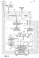
- FIG. 9 is a diagrammatical representation of a control architecture for a brake specific nitrogen oxide emission in accordance with an exemplary embodiment of the present technique.
- FIG. 10 is a flow chart illustrating exemplary steps involved in a process of controlling engine exhaust emission and fuel efficiency in accordance with an exemplary embodiment of the present technique.
- a power unit 10 e.g. locomotive power unit having engine exhaust emission and specific fuel consumption control features is illustrated in accordance with certain embodiments of the present technique.
- the disclosed embodiments are configured to reduce specific fuel consumption (SFC) by controlling actual exhaust emissions (e.g., brake specific nitrogen oxide emissions) more closely (e.g., smaller gap) to the predetermined limits, e.g., emissions standards set by the Environmental Protection Agency (EPA) or another regulatory authority.
- SFC specific fuel consumption
- the disclosed embodiments use closed-loop control based on various engine feedback and estimations, such as the brake specific nitrogen oxide emissions.
- the power unit 10 may be used for other higher horsepower engine applications.
- the power unit 10 includes a compression-ignition engine, e.g. diesel engine 12 , and a plurality of sensors 14 coupled to the engine 12 .
- a controller 16 is communicatively coupled to the sensors 14 .
- controller 16 may be a digital controller or a analog controller.
- the sensors 14 are configured to output a plurality of sensed parameters related to the engine 12 to the controller 16 .
- the sensed parameters may include intake parameters, output parameters, and environmental conditions of the engine 12 .
- the intake parameters may correspond to air intake, fuel intake, ignition timing, and so forth.
- the output parameters may correspond to exhaust emissions, output horsepower, output torque, output speed, and so forth.
- the controller 16 includes an emission compliance comparator 18 configured to compare estimated actual brake specific nitrogen oxide emission (BSNOX) levels 22 with a predetermined target brake specific nitrogen oxide emission levels 20 for each discrete notch among a plurality of throttle notches of the engine 12 .
- the estimation of the actual brake specific nitrogen oxide emission levels is explained in greater detail with reference to subsequent figures below.
- the comparison step is represented by the block 24 . If the estimated brake specific nitrogen oxide emission levels 22 is less than the predetermined target brake specific nitrogen oxide emission levels 20 , the controller 16 controls one or more control variables of the engine 12 to increase fuel efficiency as represented by the block 26 .
- the controller 16 controls one or more control variables of the engine 12 to reduce engine exhaust emissions as represented by the block 28 .
- the control variables include fuel injection timing, inlet manifold air temperature, or a combination thereof of the engine.
- the control variables may include engine power, speed of the engine, turbo boost pressure, valve timing, exhaust pressure, or the like.
- the power unit 10 having engine exhaust emission and specific fuel consumption control features is illustrated in accordance with an exemplary embodiment of the present technique.
- the controller 16 is communicatively coupled to the sensors 14 .
- the sensors 14 are configured to output a plurality of sensed parameters related to the engine 12 to the controller 16 .
- the sensors 14 may include a nitrogen oxide (NOX) sensor configured to measure the nitrogen oxide emissions in parts per million (ppm) of exhaust gas emitted from the engine 12 . It should be noted that nitrogen oxide emissions include nitrogen monoxide (NO), nitrogen dioxide (NO2), and other oxides of nitrogen.
- NOX nitrogen oxide
- nitrogen oxide emissions include nitrogen monoxide (NO), nitrogen dioxide (NO2), and other oxides of nitrogen.
- the controller 16 includes an emission estimator 30 configured to estimate the actual brake specific nitrogen oxide emission levels 22 based on the measured nitrogen oxide emissions in parts per million and other sensed parameters of the engine.
- the actual brake specific nitrogen oxide emissions are calculated as follows.
- the molar fraction of carbon compounds in the exhaust gas stream is calculated based on the following relation:
- W f is the fuel flow rate
- MW fuel is the molecular weight of the fuel
- X is the molar fraction of carbon compounds in the exhaust gas stream
- 454 is a constant to convert pounds per hour to grams per hour.
- the number of moles of NO X in the exhaust gas stream is calculated based on the following relation:
- ppm NOX 10 6 NO X ⁇ moles ⁇ / ⁇ hr
- ppm NOX is the concentration of NO x .
- the moles of NO X is converted to grams of NO X based on the following relation:
- E NOX ⁇ ( grams ⁇ / ⁇ hr ) K NOX ⁇ MW NO2 ⁇ number ⁇ ⁇ of ⁇ ⁇ moles ⁇ ⁇ of ⁇ ⁇ NO X ⁇ / ⁇ hr ⁇ 454
- E NOX K NOX ⁇ MW NOX ⁇ ppm NOX 10 6 ⁇ W f ⁇ 454 MW fuel ⁇ X
- MW NOX is the molecular weight of NO X
- K NOX is the correction factor and is dependent on inlet air temperature and relative humidity.
- the grams of NO X calculation is normalized based on the relation below:
- the power unit 10 may include a plurality of discrete (e.g., notch) throttle settings 32 for the engine 12 .
- the power unit 10 may include eight discrete notch settings of the engine 12 .
- the controller 16 includes an emission target optimizer 34 configured to calculate optimal target brake specific nitrogen oxide emission levels 20 for each discrete notch of the engine 12 so as to maintain overall average weighted nitrogen oxide emissions within predetermined limits.
- the average weighted nitrogen oxide emissions are maintained at 5.5 grams per horse power-hour.
- the optimal target brake specific nitrogen oxide emissions may be calculated based on engine operating conditions and the environmental conditions of the engine 12 .
- the controller 16 includes the emission compliance comparator 18 configured to compare the estimated actual brake specific nitrogen oxide emission (BSNOX) levels 22 with the predetermined target brake specific nitrogen oxide emission levels 20 for each discrete notch among a plurality of throttle notches of the engine 12 .
- controller 16 may include a trade-off controller 36 configured to control the one or more control variables of the engine 12 so as to decrease specific fuel consumption by reducing a gap between the estimated brake specific nitrogen oxide emissions 22 and the predetermined target brake specific nitrogen oxide emissions 20 of the engine.
- the comparison step is represented by the block 24 . If the estimated brake specific nitrogen oxide emission levels are less than the predetermined target brake specific nitrogen oxide emission levels, the controller 16 generates control signals 37 to control one or more control variables of the engine 12 to increase fuel efficiency with resulting emission increase as represented by the block 26 . If the estimated brake specific nitrogen oxide emission levels is greater than the predetermined target brake specific nitrogen oxide emission levels, the controller 16 generates control signals 37 to control one or more control variables of the engine 12 to reduce engine exhaust emissions with resulting decrease in fuel efficiency as represented by the block 28 . As appreciated, the nitrogen oxide emissions and the specific fuel consumption have an inverse relation. In other words, a reduction in brake specific nitrogen oxide emissions results in an equivalent increase in specific fuel consumption. It should be noted herein that the exemplary controller 16 performs a closed-loop control of nitrogen oxide emissions of the engine 12 so as to decrease specific fuel consumption while ensuring emission compliance of the nitrogen oxide emissions.
- a turbocharged system e.g., locomotive power unit 10 having engine exhaust emission and fuel efficiency control logic 38 is illustrated in accordance with certain embodiments of the present technique.
- the locomotive power unit 10 includes a turbocharger 40 and the compression-ignition engine, e.g. diesel engine 12 .
- the compression-ignition engine e.g. diesel engine 12 .
- embodiments of the present invention provide monitoring and control features, such as sensors and control logic, to control engine exhaust emissions while optimizing specific fuel consumption (SFC) within the locomotive power unit 10 .
- SFC specific fuel consumption
- brake specific nitrogen oxide emission of the engine 12 is estimated based on a plurality of sensed parameters, and one or more control variables of the engine is controlled to maintain the brake specific nitrogen oxide emissions within predetermined limits based at least in part on the estimated BSNOx emission.
- the sensed parameters may include exhaust gas parameters, fuel flow rate, output power, and environmental conditions of the engine 12 .
- the control variables include fuel injection timing, an inlet manifold air temperature, engine power,
- the illustrated engine 12 includes an air intake manifold 42 and an exhaust manifold 44 .
- the turbocharger 40 includes a compressor 46 and a turbine 48 and is operated to supply compressed air to the intake manifold 42 for combustion within a cylinder 50 .
- the turbine 48 is coupled to the exhaust manifold 44 .
- the exhaust gases ejected from the exhaust manifold 44 are expanded through the turbine 48 , thereby forcing rotation of a turbocharger shaft 52 connected to the compressor 46 .
- the compressor 46 draws in ambient air through an air filter 54 and provides compressed air to a heat exchanger 56 .
- the temperature of air is increased due to compression through the compressor 46 .
- the compressed air flows through the heat exchanger 56 such that the temperature of air is reduced prior to delivery into the intake manifold 42 of the engine 12 .
- the heat exchanger 56 is an air-to-water heat exchanger, which utilizes a coolant to facilitate removal of heat from the compressed air.
- the heat exchanger 56 is an air-to-air heat exchanger, which utilizes ambient air to facilitate removal of heat from compressed air.
- the heat exchanger 56 utilizes a combination of a coolant and ambient air to facilitate removal of heat from compressed air.
- the power unit 10 also includes the closed-loop emission and fuel efficiency controller 16 .
- the controller 16 is an electronic logic controller that is programmable by a user.
- the controller 16 is an electronic fuel injection controller for the engine 12 .
- the controller 16 receives a plurality of signals indicative of engine exhaust gas parameters including percentage of carbon dioxide, parts per million of nitrogen oxide emissions, parts per million of hydrocarbon, and parts per million of carbon monoxide from a carbon dioxide sensor 58 , nitrogen oxide sensor 60 , hydrocarbon sensor 62 , and carbon monoxide sensor 64 respectively.
- the controller 16 also receives a flow rate signal 66 from a fuel flow rate sensor 68 and power signal 70 from an output power sensor 72 provided to the engine 12 , and manifold pressure and temperature from a temperature sensor ( 74 ) and a pressure sensor 78 .
- the controller 16 further receives a plurality of signals indicative of environmental conditions of the engine 12 such as relative humidity (H or RH), barometric pressure, and ambient temperature.
- HVAC relative humidity
- the power unit 10 may include other sensors such as oxygen sensor, engine speed sensor, manifold air pressure (MAP) sensor, inlet airflow rate sensor, or the like.
- the controller 16 is configured to estimate a brake specific nitrogen oxide emission based on the plurality of sensed parameters described and control one or more variables of the engine 12 to maintain the brake specific nitrogen oxide emission within predetermined limits.
- the control variables include fuel injection timing, inlet manifold air temperature, engine power, speed of the engine, or a combination thereof of the engine 12 .
- the actual brake specific nitrogen oxide emissions are calculated as follows using stoiciometric analysis.
- the analysis involves solving the following elemental balance equations using matrix inversion:
- the above linear equations are solved to calculate the number of moles of NO X .
- the humidity correction factor (K NOX ) may be calculated as mentioned above with reference to FIG. 2 .
- the brake specific nitrogen oxide emission is calculated based on the number of moles of NO X .
- the controller 16 is configured to control a fuel injection timing to maintain the brake specific nitrogen oxide emission within predetermined limits.
- the specific fuel consumption of the engine is also maintained within the predetermined limits.
- the controller 16 may be operable to produce a pressure signal 73 to control operation of a plurality of fuel injection pumps 77 .
- the pumps 77 drive a plurality of fuel injectors 79 for injecting fuel into the plurality of cylinders 50 of the engine 12 .
- the fuel injector 79 is an electrically actuated fuel injector.
- the fuel injector 79 typically injects fuel into the engine cylinder 50 as a function of a fuel injection signal 80 received from the controller 16 .
- the fuel injection signal 80 may include waveforms that are indicative of a desired injection rate, desired fuel injection timing, quantity of fuel to be injected into the cylinder 50 , or the like.
- a piston 82 is slidably disposed in each cylinder 50 and reciprocates between a top dead center and a bottom dead center position. If the injection timing is advanced (i.e. inject before top dead center), the pressure and temperature of gases in the cylinder 50 increases, resulting in an increase in the engine exhaust emissions. However, engine 12 generates higher power for same amount of fuel. By advancing the fuel injection timing a certain amount, a lower quantity of fuel is required to produce the same power while maintaining the engine exhaust emissions within predetermined limits.
- the disclosed embodiments ensure that the emissions do not exceed the predetermined limits.
- the advanced timing results in a smaller gap between the estimated/actual BSNOx and the predetermined limits (e.g., set by emissions standards/regulations).
- the controller 16 having engine exhaust emission and fuel efficiency control logic 38 is illustrated in accordance with embodiments of the present technique.
- the controller 16 receives sensor signals from a plurality of sensors, such as the NOX sensor 60 , CO2 sensor 58 , HC sensor 62 , CO sensor 64 , oxygen sensor 86 , fuel flow rate sensor 68 , engine speed sensor 88 , engine horsepower sensor 72 , manifold air temperature (MAT) sensor 74 , manifold air pressure (MAP) sensor 90 , inlet air flow rate sensor 92 , relative humidity (RH) sensor 76 , and barometric pressure sensor 78 .
- the oxygen sensor 86 is configured to detect the quantity of oxygen in the exhaust gas.
- the speed sensor 88 is configured to detect speed of the engine.
- the MAP sensor 90 is configured to detect the pressure of air at the intake manifold 42 of the engine 12 .
- Air flow rate sensor 92 is configured to detect the air flow rate at the intake manifold 42 of the engine 12 .
- the controller 16 is communicatively coupled to the sensors 14 .
- the sensors 14 are configured to output the plurality of sensed parameters related to the engine 12 to the controller 16 .
- the controller 16 includes the emission estimator 30 configured to estimate the actual brake specific nitrogen oxide emission levels 22 based on the plurality of sensed parameters.
- the power unit 10 includes the plurality of discrete (e.g., notch) throttle settings for the engine 12 .
- the controller 16 includes the emission target optimizer 34 configured to calculate optimal target brake specific nitrogen oxide emission levels for each discrete notch of the engine 12 so as to maintain an overall average weighted nitrogen oxide emissions within predetermined limits.
- the optimal target brake specific nitrogen oxide emissions may be calculated based on engine operating conditions and the environmental conditions of the engine 12 .
- the estimated actual brake specific nitrogen oxide emission (BSNOX) levels are compared with the predetermined target brake specific nitrogen oxide emission levels for each discrete notch among a plurality of throttle notches of the engine 12 .
- controller 16 controls the one or more control variables of the engine 12 so as to decrease specific fuel consumption by reducing a gap between the estimated brake specific nitrogen oxide emissions 22 and the predetermined target brake specific nitrogen oxide emissions 20 of the engine.
- the controller 16 generates control signals 37 to control one or more variables of the engine 12 based on the comparison of the estimated brake specific nitrogen oxide emission levels with the predetermined target brake specific nitrogen oxide emission levels.
- the controller 16 may include a sensor monitoring logic 94 configured to monitor operating conditions of the plurality of sensors 14 . The sensor operating condition is checked as represented by block 96 . If the sensor operating condition is normal, the controller 16 performs control of one or more control variables of the engine so as to control engine exhaust emissions and fuel efficiency of the engine as discussed above. If the sensor operating condition is abnormal, the controller 16 reverts to conservative settings that assure that engine exhaust emissions and fuel efficiency is maintained within predetermined limits.
- the controller 16 may include conservative emissions compliance control logic 98 configured to enable the controller 16 to revert to conservative settings.
- the power unit 10 includes the turbocharger 40 and the diesel engine 14 .
- the power unit 10 may be used for driving a system 100 .
- the system 100 may include locomotive engine, automobile engine, marine engine, or the like.
- the system 100 also may include a vehicle, such as a locomotive, an automobile, a boat, an aircraft, and so forth.
- the system 100 may include a power generation system, industrial automation system, and so forth.
- the power unit 10 includes the controller 16 .
- the controller 16 receives sensor signals from a plurality of sensors, such as the NO X sensor 60 , CO2 sensor 58 , HC sensor 62 , CO sensor 64 , fuel flow rate sensor 68 , engine horse power sensor 72 , manifold air temperature (MAT) sensor 74 , relative humidity sensor 76 , and barometric pressure sensor 78 .
- the controller 32 may be operable to produce the fuel injection signal 80 to control operation of the plurality of fuel injectors 79 .
- the controller 16 is configured to regulate control variables including injection timing, inlet manifold air temperature, engine power, speed of the engine, or a combination thereof of the engine.
- the controller 16 performs a closed-loop control of nitrogen oxide emissions of the engine 12 so as decrease specific fuel consumption while ensuring emission compliance of the nitrogen oxide emissions.
- the controller uses various sensed data and estimated data (e.g., BSNOx) to control engine parameters to cause a decrease in the specific fuel consumption without raising the emissions (e.g., BSNOx) above the predetermined limits.
- the closed-loop control scheme may cause the actual BSNOx emissions to approach but not exceed the predetermined limits in order to reduce the specific fuel consumption.
- the controller 34 may further include a database 102 , an algorithm 104 , and a data analysis block 106 .
- the database 102 may be configured to store predefined information about the power unit 10 .
- the database 102 may store information relating to fuel injection timing, engine speed, engine power, intake manifold air temperature, exhaust gas temperature, exhaust gas composition, or the like.
- the database 94 may also include instruction sets, maps, lookup tables, variables, or the like. Such maps, lookup tables, instruction sets, are operative to correlate characteristics of the fuel efficiency and nitrogen oxide emissions to specified engine operation parameters such as engine speed, fuel injection timing, intake manifold air temperature and pressure, exhaust gas composition, or the like.
- the database 94 may be configured to store actual sensed/detected information from the above-mentioned sensors.
- the algorithm 96 facilitates the processing of signals from the above-mentioned plurality of sensors.
- the data analysis block 106 may include a variety of circuitry types, such as a microprocessor, a programmable logic controller, a logic module, etc.
- the data analysis block 106 in combination with the algorithm 96 may be used to perform the various computational operations relating to determination of brake specific nitrogen oxide emissions, fuel injection timing, fuel injection rate, number of fuel injections, the fuel injection quantity, timing, inlet manifold air temperature and pressure, engine power, speed of the engine, or a combination thereof. Any of the above mentioned parameters may be selectively and/or dynamically adapted or altered relative to time.
- the nitrogen oxide emissions of the engine are dependent on a plurality of factors including inlet manifold air temperature (MAT), advance angle (AA), barometric pressure, engine speed, engine horsepower, or the like.
- MAT manifold air temperature
- AA advance angle
- barometric pressure engine speed
- engine horsepower or the like.
- the technique involves performing design of experiments (DOE) and regression analysis to illustrate variation of advance angle versus nitrogen oxide emissions for a plurality of notches of the engine as represented by the block 108 .
- DOE and regression analysis facilitates to characterize the engine behavior for different operating conditions.
- the results of DOE are used to build a transfer function between parameters such as engine horsepower, advance angle, engine speed, manifold air temperature, barometric pressure and brake specific nitrogen oxide emissions.
- NO x f (engine parameters,notch, EPA duty cycle)
- SFC f (engine parameters,notch, AAR duty cycle)
- the engine parameters may include manifold air temperature (MAT), advance angle (AA), barometric pressure, or the like.
- MAT manifold air temperature
- AA advance angle
- barometric pressure or the like.
- the transfer functions for plurality of notches, for example, notch 1 , notch 2 , or the like are represented by the blocks 110 , 112 .
- An optimization model was derived so as to control specific fuel consumption while maintaining brake specific nitrogen oxide emissions within predetermined limits as represented by the block 114 .
- the optimization model is represented as follows: ⁇ NO Xi i D epa — i i ⁇ EPANO XLimit Min ⁇ SFC i D aar — i where NO Xi is the emission at notch “i”, D epa — i is the EPA duty cycle (i.e. duty cycle set by the environmental protection agency), SFC i is the specific fuel consumption at notch “i”, D aar — i is the AAR duty cycle.
- the EPANO Xlimit (NO X limit set by environmental protection agency) is equal to 5.5 grams per horse-power hour.
- the exhaust emissions are maintained within predetermined limits as represented by block 116 and represented as follows: ⁇ PM i D epa — i ⁇ PM limit ⁇ HC i D epa — i ⁇ HC limit ⁇ CO i D epa — i ⁇ CO limit where PM i is the particulate matter emission at notch “i”, HC i is the hydrocarbon emission at notch “i”, CO i is the carbon monoxide emission at notch “i”.
- the engine operating parameters are maintained within predetermined limits as represented by the block 118 and represented as follows: max( PTT i ) ⁇ PTT limit max( FV i ) ⁇ FV limit max( TS i ) ⁇ TS limit max( Pcyc i ) ⁇ Pcyc limit where PTT is the pre-turbine temperature, FV is the fuel value, TS is the turbine speed, and Pcyc is the peak cylinder pressure.
- PTT is the pre-turbine temperature
- FV the fuel value
- TS the turbine speed
- Pcyc the peak cylinder pressure.
- manifold air temperature is constant for a predetermined notch.
- the brake specific nitrogen oxide emission varies with change in the advance angle.
- the specific consumption for the optimized advance angle 120 is calculated using the transfer functions.
- FIG. 7 diagrammatical representation of a Monte Carlo analysis technique configured to estimate sensor accuracy required in accordance with an exemplary embodiment of the present technique is illustrated.
- the standard deviation of sensor readings is estimated and a normal distribution is defined.
- random and bias error of relative humidity sensor, temperature sensor, and NOX sensor are represented as normal distributions 122 , 124 , 126 respectively.
- the brake specific nitrogen oxide emission is estimated for each notch settings based on the sensor readings of the relative humidity sensor, temperature sensor, and NOX sensor as described above and is represented by the block 128 .
- the estimated brake specific nitrogen oxide emission for each notch settings may be represented as normal distribution.
- the resulting estimated brake specific nitrogen oxide emission distribution for each notch was weighed by the EPA duty cycle as represented by the block 130 .
- a buffer value equivalent to 3 times sigma (3 ⁇ ) is estimated from the resulting estimated brake specific nitrogen oxide emission distribution as represented by the normal distribution 132 .
- the actual brake specific nitrogen oxide emissions are maintained within the buffer value.
- the NOX sensor includes a Zirconia based oxygen sensor.
- the quantity of oxygen in the exhaust gas stream is measured using the oxygen sensor.
- the nitrogen oxide emission (NOX) is dissociated to nitrogen and oxygen downstream of the oxygen sensor.
- the quantity of oxygen is again measured.
- the difference in quantity between the initial measurement and subsequent measurement of oxygen is equal to the concentration of NOX.
- the concentration of oxygen is represented by the following relation:
- the brake specific nitrogen oxide emission may be estimated using airflow measurement represented by the following relation:
- a f is the airflow rate
- MW air is the molecular weight of air.
- an alternate approach is to estimate airflow using existing sensors. Theoretical airflow (Af theoretical ) into the cylinders is calculated using displacement volume (Vd), density of intake air ( ⁇ ) and the engine rpm (N) as follows:
- the density of intake air may be calculated from ideal gas law if the inlet manifold air temperature and pressure are known.
- the theoritical airflow (Af theoritical ) is calculated based on the following relation:
- Af theoritical MAP ⁇ V d ⁇ N R ⁇ MAT ⁇ 2 ⁇ 60
- MAP manifold air pressure
- MAT manifold air temperature
- R a gas constant in joules/Kilogram/Kelvin.
- volumetric efficiency Af actual Af theoritical
- the volumetric efficiency is typically a function of engine speed, exhaust pressure, and manifold air pressure.
- the only parameter, that varies, is the engine speed. If the breathing characteristic of the engine defined by the volumetric efficiency is calibrated, then the actual airflow can be calculated as:
- Af actaul MAP ⁇ V d ⁇ N R ⁇ MAT ⁇ 2 ⁇ 60 ⁇ ⁇ vol ⁇ ( P exh , P MAP , N )
- P exh is the exhaust pressure
- P MAP is the manifold pressure
- N is the engine speed.
- the electronic controller 16 is communicatively coupled to the sensors 14 .
- the sensors 14 are configured to output a plurality of sensed parameters related to the engine to the controller 16 .
- the controller 16 includes the emission estimator configured to estimate the actual brake specific nitrogen oxide emission levels based on the measured nitrogen oxide emissions in parts per million as represented by block 22 .
- the controller 16 may also include a fuel estimator configured to estimate instantaneous fuel flow rate as represented by the block 136 .
- the controller 16 may also include an air estimator configured to estimate volume of air flowing into the cylinders.
- the controller 16 includes a fuel governor 138 configured to regulate fuel flow to the engine.
- controller 16 may include a trade-off controller 36 configured to control the one or more control variables of the engine 12 so as to decrease specific fuel consumption by reducing a gap between the estimated brake specific nitrogen oxide emissions 22 and the predetermined target brake specific nitrogen oxide emissions 20 of the engine.
- the controller 16 is further configured to estimate the duration of valve opening time of the fuel injector coupled to the engine as represented by the block 140 .
- the controller 16 estimates and regulates advance angle of the fuel injector i.e. start of fuel injection into the engine cylinder as represented by the block 142 .
- the advance angle is computed based on factors such as fuel injection timing, manifold air temperature, wheel slip, and transition from one notch to the other.
- the injection timing may be varied depending on changes in the manifold air temperature as represented by the block 144 .
- the controller 16 compares the estimated actual brake specific nitrogen oxide emission (BSNOX) levels with the predetermined target brake specific nitrogen oxide emission levels for each discrete notch among the plurality of throttle notches of the engine.
- controller 16 also includes the trade-off controller 36 configured to control the one or more control variables such as fuel injection timing of the engine 12 so as to decrease specific fuel consumption by reducing a gap between the estimated brake specific nitrogen oxide emissions and the predetermined target brake specific nitrogen oxide emissions of the engine.
- the controller 36 varies the fuel injection timing based on a comparison of the estimated actual brake specific nitrogen oxide emission (BSNOX) levels and the predetermined target brake specific nitrogen oxide emission levels 20 .
- the method includes outputting a plurality of sensed parameters related to the engine to the controller.
- the controller receives a plurality of signals indicative of engine exhaust gas parameters including percentage of carbon dioxide, percentage of oxygen from an oxygen sensor, parts per million of nitrogen oxide emissions, parts per million of hydrocarbon, and parts per million of carbon monoxide from a carbon dioxide sensor, nitrogen oxide sensor, hydrocarbon sensor, and carbon monoxide sensor respectively as represented by the step 146 .
- the controller also receives a flow rate signal from a fuel flow rate sensor and power signal from an output power sensor provided to the engine as represented by the step 148 .
- the controller also receives an air flow rate signal from air flow rate sensor and power signal from an output power sensor provided to the engine.
- the controller further receives a plurality of sensor signals indicative of environmental conditions of the engine such as ambient air temperature, relative humidity, and barometric pressure as represented by the step 150 .
- nitrogen oxide emissions include nitrogen oxide (NO), nitrogen dioxide (NO2), or the like. Since the NOx sensor detects the relative amount of NOx in the exhaust gas stream, the NOx measured in ppm is converted to brake specific nitrogen oxide emissions to compute the actual mass flow of NOx in the exhaust gas stream. The controller estimates the actual brake specific nitrogen oxide emission levels based on the plurality of sensed parameters as represented by the step 152 .
- the controller further calculates optimal target brake specific nitrogen oxide emission levels for each discrete notch of the engine so as to maintain an overall average weighted nitrogen oxide emissions within predetermined limits.
- the average weighted nitrogen oxide emissions are maintained at 5.5 grams per horse power-hour.
- the controller compares the estimated actual brake specific nitrogen oxide emission (BSNOX) levels with the predetermined target brake specific nitrogen oxide emission levels for each discrete notch among a plurality of throttle notches of the engine as represented by the step 154 .
- the controller 16 further controls the one or more control variables of the engine so as to decrease specific fuel consumption by reducing a gap between the estimated brake specific nitrogen oxide emissions and the predetermined target brake specific nitrogen oxide emissions of the engine as represented by the step 156 .
- the controller If the estimated brake specific nitrogen oxide emission levels are less than the predetermined target brake specific nitrogen oxide emission levels, the controller generates control signals to control one or more control variables of the engine to increase fuel efficiency with resulting increase in emissions (but still within predefined limits). If the estimated brake specific nitrogen oxide emission levels is greater than the predetermined target brake specific nitrogen oxide emission levels, the controller generates control signals to control one or more control variables of the engine to reduce engine exhaust emissions with resulting decrease in fuel efficiency. It should be noted herein that the exemplary controller performs a closed-loop control of nitrogen oxide emissions of the engine so as decrease specific fuel consumption while ensuring emission compliance of the nitrogen oxide emissions. Moreover, the method of FIG. 10 and the logic illustrated in FIGS.
- FIGS. 1-9 may be incorporated into a computer-readable medium, such as a computer, a computer disk, a memory chip, an electronic control unit (ECU) of the engine 12 , or another tangible medium that can be read by a computer or the like.
- ECU electronice control unit
- the logical steps of FIGS. 1 - 10 may be described as, or a part of, a computer-implemented method. Accordingly, the embodiments illustrated and described with reference to FIGS. 1-10 may include computer code, instructions, or logic that is readable and executable on a processor, programmable control unit (PCU), or the like.
- PCU programmable control unit
Abstract
Description
where CO2 is the percent concentration of carbon dioxide, ppmHC is the parts per million concentration of hydrocarbon, ppmCO is the parts per million concentration of carbon monoxide. The number of moles of exhaust is calculated based on the following relation:
where Wf is the fuel flow rate, and MWfuel is the molecular weight of the fuel, X is the molar fraction of carbon compounds in the exhaust gas stream, 454 is a constant to convert pounds per hour to grams per hour. The number of moles of NOX in the exhaust gas stream is calculated based on the following relation:
where ppmNOX is the concentration of NOx. The moles of NOX is converted to grams of NOX based on the following relation:
where MWNOX is the molecular weight of NOX, KNOX is the correction factor and is dependent on inlet air temperature and relative humidity. The grams of NOX calculation is normalized based on the relation below:
where HP is the engine horse power.
where y is the fuel flow, H is the relative humidity, MWair is the molecular weight of air, MWH2O is the molecular weight of water, α is the hydrogen to carbon ratio, and a, b, c, d, e, f, g, x, y, z are 10 unknown molar values. The above linear equations are solved to calculate the number of moles of NOX. The humidity correction factor (KNOX) may be calculated as mentioned above with reference to
NO x =f(engine parameters,notch,EPA duty cycle)
SFC=f(engine parameters,notch,AAR duty cycle)
The engine parameters may include manifold air temperature (MAT), advance angle (AA), barometric pressure, or the like. The transfer functions for plurality of notches, for example,
ΣNO Xi
MinΣSFC i D aar
where NOXi is the emission at notch “i”, Depa
ΣPM i D epa
ΣHC i D epa
ΣCO i D epa
where PMi is the particulate matter emission at notch “i”, HCi is the hydrocarbon emission at notch “i”, COi is the carbon monoxide emission at notch “i”. The engine operating parameters are maintained within predetermined limits as represented by the
max(PTT i)≦PTT limit
max(FV i)≦FV limit
max(TS i)≦TS limit
max(Pcyc i)≦Pcyc limit
where PTT is the pre-turbine temperature, FV is the fuel value, TS is the turbine speed, and Pcyc is the peak cylinder pressure. For normal operating conditions, manifold air temperature is constant for a predetermined notch. The brake specific nitrogen oxide emission varies with change in the advance angle. The specific consumption for the optimized
Alternatively, the brake specific nitrogen oxide emission may be estimated using airflow measurement represented by the following relation:
The density of intake air may be calculated from ideal gas law if the inlet manifold air temperature and pressure are known. The theoritical airflow (Aftheoritical) is calculated based on the following relation:
where MAP is the manifold air pressure, MAT is the manifold air temperature, and R is a gas constant in joules/Kilogram/Kelvin. In actual practice there are losses due to flow across valves, inertia of the air mass or the like. The factors are lumped into what is known as the volumetric efficiency (ηvol) and is defined below:
The volumetric efficiency is typically a function of engine speed, exhaust pressure, and manifold air pressure. For a locomotive type operation with steady state notch conditions, the only parameter, that varies, is the engine speed. If the breathing characteristic of the engine defined by the volumetric efficiency is calibrated, then the actual airflow can be calculated as:
where Pexh is the exhaust pressure, PMAP is the manifold pressure, and N is the engine speed.
Claims (15)
Priority Applications (2)
| Application Number | Priority Date | Filing Date | Title |
|---|---|---|---|
| US11/641,204 US8103429B2 (en) | 2006-12-19 | 2006-12-19 | System and method for operating a compression-ignition engine |
| PCT/US2007/084911 WO2008079548A1 (en) | 2006-12-19 | 2007-11-16 | System and method for operating a compression-ignition engine |
Applications Claiming Priority (1)
| Application Number | Priority Date | Filing Date | Title |
|---|---|---|---|
| US11/641,204 US8103429B2 (en) | 2006-12-19 | 2006-12-19 | System and method for operating a compression-ignition engine |
Publications (2)
| Publication Number | Publication Date |
|---|---|
| US20080147295A1 US20080147295A1 (en) | 2008-06-19 |
| US8103429B2 true US8103429B2 (en) | 2012-01-24 |
Family
ID=39319636
Family Applications (1)
| Application Number | Title | Priority Date | Filing Date |
|---|---|---|---|
| US11/641,204 Expired - Fee Related US8103429B2 (en) | 2006-12-19 | 2006-12-19 | System and method for operating a compression-ignition engine |
Country Status (2)
| Country | Link |
|---|---|
| US (1) | US8103429B2 (en) |
| WO (1) | WO2008079548A1 (en) |
Cited By (10)
| Publication number | Priority date | Publication date | Assignee | Title |
|---|---|---|---|---|
| US20120022728A1 (en) * | 2010-07-22 | 2012-01-26 | Edward Joseph Hall | Method and system for engine emission control |
| US20130098054A1 (en) * | 2011-10-14 | 2013-04-25 | Alstom Technology Ltd. | Method for Operating a Gas Turbine |
| US9255518B2 (en) | 2013-10-24 | 2016-02-09 | Norfolk Southern Corporation | System and method for an aftercooler bypass |
| US9518521B2 (en) | 2014-07-21 | 2016-12-13 | General Electric Company | System for controlling emissions of engine and related method and non transitory computer readable media |
| US20170152806A1 (en) * | 2015-12-01 | 2017-06-01 | General Electric Company | Method and systems for airflow control |
| US9810672B2 (en) | 2014-12-04 | 2017-11-07 | Caterpillar Inc. | Method of operating an engine |
| US9868089B2 (en) | 2014-07-21 | 2018-01-16 | General Electric Company | System for controlling emissions of engine and related method and non-transitory computer readable media |
| US10480474B2 (en) | 2017-04-06 | 2019-11-19 | Ge Global Sourcing Llc | Method and system for determining remaining useful life for an injector of a reciprocating engine |
| US10508606B2 (en) | 2014-10-22 | 2019-12-17 | Ge Global Sourcing Llc | Method and systems for airflow control |
| US10563596B2 (en) | 2017-03-31 | 2020-02-18 | Generac Power Systems, Inc. | Carbon monoxide detecting system for internal combustion engine-based machines |
Families Citing this family (11)
| Publication number | Priority date | Publication date | Assignee | Title |
|---|---|---|---|---|
| US8215589B2 (en) * | 2004-01-23 | 2012-07-10 | Janeke Charl E | Reversible space plane |
| WO2009076659A1 (en) * | 2007-12-12 | 2009-06-18 | Foss Maritime Company | Hybrid propulsion systems |
| FR2938018A1 (en) * | 2008-11-06 | 2010-05-07 | Renault Sas | Compression ignition internal combustion engine i.e. diesel engine, controlling method for motor vehicle, involves determining adjustments of functioning point of engine according to emission parameter |
| US8538659B2 (en) * | 2009-10-08 | 2013-09-17 | GM Global Technology Operations LLC | Method and apparatus for operating an engine using an equivalence ratio compensation factor |
| FR2959278A3 (en) * | 2010-04-27 | 2011-10-28 | Renault Sa | Method for controlling internal combustion petrol engine of vehicle, involves allowing internal combustion petrol engine to take two operating modes, and adopting one of operating modes, when processing device process nitrogen oxides |
| US8683844B2 (en) * | 2011-08-31 | 2014-04-01 | GM Global Technology Operations LLC | Sensor monitoring methods and systems |
| IN2014MN00741A (en) | 2011-10-05 | 2015-07-03 | Engineered Propulsion Systems Inc | |
| WO2016074879A1 (en) * | 2014-11-10 | 2016-05-19 | Fev Gmbh | Method for operating an internal combustion engine comprising a lean nox trap |
| JP6584512B2 (en) * | 2015-09-02 | 2019-10-02 | 三菱電機株式会社 | Simulation apparatus and simulation program |
| CN111108275B (en) | 2017-07-21 | 2023-02-24 | 工程推进系统有限公司 | Enhanced aviation diesel engine |
| US11008922B2 (en) | 2018-12-12 | 2021-05-18 | Cummins Inc. | System and method for diagnosing health of an exhaust aftertreatment system |
Citations (15)
| Publication number | Priority date | Publication date | Assignee | Title |
|---|---|---|---|---|
| WO1982000857A1 (en) | 1979-08-27 | 1982-03-18 | J Bailey | Apparatus for controlling the quantity of fuel delivery to an engine and engine timing |
| US5709196A (en) * | 1996-09-24 | 1998-01-20 | Caterpillar Inc. | Fuel control system for an internal combustion engine using a low cetane quality fuel |
| US5765372A (en) * | 1994-09-06 | 1998-06-16 | Mazda Motor Corporation | Lean burn engine for automobile |
| EP0889222A2 (en) | 1997-07-02 | 1999-01-07 | Cummins Engine Company, Inc. | Air/fuel ratio control method for a lean burn combustion engine |
| EP0916830A2 (en) | 1997-11-14 | 1999-05-19 | Toyota Jidosha Kabushiki Kaisha | Pilot injection control apparatus for an internal combustion engine |
| US6354269B1 (en) | 1999-09-29 | 2002-03-12 | Mazda Motor Corporation | Method and system for controlling engine |
| US6360159B1 (en) * | 2000-06-07 | 2002-03-19 | Cummins, Inc. | Emission control in an automotive engine |
| US6382177B1 (en) | 1999-08-18 | 2002-05-07 | Mazda Motor Corporation | Fuel injection control system for a diesel engine |
| US20020147558A1 (en) * | 1999-06-03 | 2002-10-10 | Robert Bosch Corporation | Ultrasound transducer temperature compensation methods, apparatus and programs |
| EP1391601A2 (en) | 2002-08-20 | 2004-02-25 | Volkswagen Aktiengesellschaft | Method to operate an internal combustion engine with direct injection |
| US6708483B1 (en) * | 2000-03-17 | 2004-03-23 | Ford Global Technologies, Llc | Method and apparatus for controlling lean-burn engine based upon predicted performance impact |
| US20040144082A1 (en) | 2003-01-29 | 2004-07-29 | Visteon Global Technologies, Inc. | Controller for controlling oxides of nitrogen (NOx) emissions from a combustion engine |
| US20060096273A1 (en) | 2004-11-08 | 2006-05-11 | Soliman Samar S | Method and system for emission control of a compression ignition locomotive engine |
| US20070012032A1 (en) * | 2005-07-12 | 2007-01-18 | Eaton Corporation | Hybrid system comprising HC-SCR, NOx-trapping, and NH3-SCR for exhaust emission reduction |
| US7334400B2 (en) * | 2004-07-14 | 2008-02-26 | Eaton Corporation | Valveless dual leg exhaust aftertreatment system |
-
2006
- 2006-12-19 US US11/641,204 patent/US8103429B2/en not_active Expired - Fee Related
-
2007
- 2007-11-16 WO PCT/US2007/084911 patent/WO2008079548A1/en active Application Filing
Patent Citations (16)
| Publication number | Priority date | Publication date | Assignee | Title |
|---|---|---|---|---|
| WO1982000857A1 (en) | 1979-08-27 | 1982-03-18 | J Bailey | Apparatus for controlling the quantity of fuel delivery to an engine and engine timing |
| US5765372A (en) * | 1994-09-06 | 1998-06-16 | Mazda Motor Corporation | Lean burn engine for automobile |
| US5765372C1 (en) * | 1994-09-06 | 2001-07-17 | Mazda Motor | Lean burn engine for automobile |
| US5709196A (en) * | 1996-09-24 | 1998-01-20 | Caterpillar Inc. | Fuel control system for an internal combustion engine using a low cetane quality fuel |
| EP0889222A2 (en) | 1997-07-02 | 1999-01-07 | Cummins Engine Company, Inc. | Air/fuel ratio control method for a lean burn combustion engine |
| EP0916830A2 (en) | 1997-11-14 | 1999-05-19 | Toyota Jidosha Kabushiki Kaisha | Pilot injection control apparatus for an internal combustion engine |
| US20020147558A1 (en) * | 1999-06-03 | 2002-10-10 | Robert Bosch Corporation | Ultrasound transducer temperature compensation methods, apparatus and programs |
| US6382177B1 (en) | 1999-08-18 | 2002-05-07 | Mazda Motor Corporation | Fuel injection control system for a diesel engine |
| US6354269B1 (en) | 1999-09-29 | 2002-03-12 | Mazda Motor Corporation | Method and system for controlling engine |
| US6708483B1 (en) * | 2000-03-17 | 2004-03-23 | Ford Global Technologies, Llc | Method and apparatus for controlling lean-burn engine based upon predicted performance impact |
| US6360159B1 (en) * | 2000-06-07 | 2002-03-19 | Cummins, Inc. | Emission control in an automotive engine |
| EP1391601A2 (en) | 2002-08-20 | 2004-02-25 | Volkswagen Aktiengesellschaft | Method to operate an internal combustion engine with direct injection |
| US20040144082A1 (en) | 2003-01-29 | 2004-07-29 | Visteon Global Technologies, Inc. | Controller for controlling oxides of nitrogen (NOx) emissions from a combustion engine |
| US7334400B2 (en) * | 2004-07-14 | 2008-02-26 | Eaton Corporation | Valveless dual leg exhaust aftertreatment system |
| US20060096273A1 (en) | 2004-11-08 | 2006-05-11 | Soliman Samar S | Method and system for emission control of a compression ignition locomotive engine |
| US20070012032A1 (en) * | 2005-07-12 | 2007-01-18 | Eaton Corporation | Hybrid system comprising HC-SCR, NOx-trapping, and NH3-SCR for exhaust emission reduction |
Non-Patent Citations (1)
| Title |
|---|
| RD 539042, Mar. 2009. * |
Cited By (16)
| Publication number | Priority date | Publication date | Assignee | Title |
|---|---|---|---|---|
| US20120022728A1 (en) * | 2010-07-22 | 2012-01-26 | Edward Joseph Hall | Method and system for engine emission control |
| US8588999B2 (en) * | 2010-07-22 | 2013-11-19 | General Electric Company | Method and system for engine emission control |
| US20130098054A1 (en) * | 2011-10-14 | 2013-04-25 | Alstom Technology Ltd. | Method for Operating a Gas Turbine |
| US9429079B2 (en) * | 2011-10-14 | 2016-08-30 | General Electric Technology Gmbh | Method and apparatus for detecting combustion conditions in combustors of a sequential combustion gas turbine engine |
| US9255518B2 (en) | 2013-10-24 | 2016-02-09 | Norfolk Southern Corporation | System and method for an aftercooler bypass |
| US9868089B2 (en) | 2014-07-21 | 2018-01-16 | General Electric Company | System for controlling emissions of engine and related method and non-transitory computer readable media |
| US9518521B2 (en) | 2014-07-21 | 2016-12-13 | General Electric Company | System for controlling emissions of engine and related method and non transitory computer readable media |
| US10508606B2 (en) | 2014-10-22 | 2019-12-17 | Ge Global Sourcing Llc | Method and systems for airflow control |
| US11293359B2 (en) | 2014-10-22 | 2022-04-05 | Transportation Ip Holdings, Llc | Method and systems for airflow control |
| US9810672B2 (en) | 2014-12-04 | 2017-11-07 | Caterpillar Inc. | Method of operating an engine |
| US20170152806A1 (en) * | 2015-12-01 | 2017-06-01 | General Electric Company | Method and systems for airflow control |
| US10221798B2 (en) * | 2015-12-01 | 2019-03-05 | Ge Global Sourcing Llc | Method and systems for airflow control |
| US10563596B2 (en) | 2017-03-31 | 2020-02-18 | Generac Power Systems, Inc. | Carbon monoxide detecting system for internal combustion engine-based machines |
| US11248540B2 (en) | 2017-03-31 | 2022-02-15 | Generac Power Systems, Inc. | Carbon monoxide detecting system for internal combustion engine-based machines |
| US11905894B2 (en) | 2017-03-31 | 2024-02-20 | Generac Power Systems, Inc. | Carbon monoxide detecting system for internal combustion engine-based machines |
| US10480474B2 (en) | 2017-04-06 | 2019-11-19 | Ge Global Sourcing Llc | Method and system for determining remaining useful life for an injector of a reciprocating engine |
Also Published As
| Publication number | Publication date |
|---|---|
| US20080147295A1 (en) | 2008-06-19 |
| WO2008079548A1 (en) | 2008-07-03 |
Similar Documents
| Publication | Publication Date | Title |
|---|---|---|
| US8103429B2 (en) | System and method for operating a compression-ignition engine | |
| US7296555B2 (en) | System and method for operating a turbo-charged engine | |
| US7281368B2 (en) | Nox discharge quantity estimation method for internal combustion engine | |
| US7792632B2 (en) | Intake air quantity correcting device | |
| US8375714B2 (en) | System and method for operating a turbocharged engine | |
| US7630823B2 (en) | System and method for controlling the fuel injection event in an internal combustion engine | |
| JP4600469B2 (en) | Fuel property detection device and fuel property detection method | |
| US8640457B2 (en) | System and method for operating a turbocharged engine | |
| CN102597451B (en) | System and method for operating a turbocharged engine | |
| US7360522B2 (en) | System and method for operating a turbo-charged engine | |
| US20100211295A1 (en) | Fuel admission control unit to control a diesel engine | |
| US8484968B2 (en) | System and method for operating a compression-ignition engine | |
| US20040236493A1 (en) | Method for controlling an engine with an egr system | |
| US10683822B2 (en) | Fuel-cetane-number estimation method and apparatus | |
| JP2008184908A (en) | Engine control system | |
| US20160103110A1 (en) | Engine nox model | |
| US10669957B2 (en) | Method for controlling a heat engine | |
| JP2006522892A (en) | Method of operating a self-igniting internal combustion engine | |
| JP2006274845A (en) | NOx EMISSION CALCULATION DEVICE OF INTERNAL COMBUSTION ENGINE | |
| US9121363B2 (en) | Fuel injection pattern and timing | |
| WO2004027244A1 (en) | Method for controlling an engine with an egr system | |
| JP2012087743A (en) | Combustion control device and method of internal combustion engine |
Legal Events
| Date | Code | Title | Description |
|---|---|---|---|
| AS | Assignment |
Owner name: GENERAL ELECTRIC COMPANY, NEW YORK Free format text: ASSIGNMENT OF ASSIGNORS INTEREST;ASSIGNORS:SIVASUBRAMANIAM, MANTHRAM;HOUPT, PAUL KENNETH;PRIMUS, ROY JAMES;AND OTHERS;REEL/FRAME:018728/0909;SIGNING DATES FROM 20061215 TO 20061219 Owner name: GENERAL ELECTRIC COMPANY, NEW YORK Free format text: ASSIGNMENT OF ASSIGNORS INTEREST;ASSIGNORS:SIVASUBRAMANIAM, MANTHRAM;HOUPT, PAUL KENNETH;PRIMUS, ROY JAMES;AND OTHERS;SIGNING DATES FROM 20061215 TO 20061219;REEL/FRAME:018728/0909 |
|
| FEPP | Fee payment procedure |
Free format text: PAYER NUMBER DE-ASSIGNED (ORIGINAL EVENT CODE: RMPN); ENTITY STATUS OF PATENT OWNER: LARGE ENTITY Free format text: PAYOR NUMBER ASSIGNED (ORIGINAL EVENT CODE: ASPN); ENTITY STATUS OF PATENT OWNER: LARGE ENTITY |
|
| REMI | Maintenance fee reminder mailed | ||
| LAPS | Lapse for failure to pay maintenance fees | ||
| STCH | Information on status: patent discontinuation |
Free format text: PATENT EXPIRED DUE TO NONPAYMENT OF MAINTENANCE FEES UNDER 37 CFR 1.362 |
|
| FP | Lapsed due to failure to pay maintenance fee |
Effective date: 20160124 |