US8104550B2 - Methods for applying wear-resistant material to exterior surfaces of earth-boring tools and resulting structures - Google Patents
Methods for applying wear-resistant material to exterior surfaces of earth-boring tools and resulting structures Download PDFInfo
- Publication number
- US8104550B2 US8104550B2 US11/864,482 US86448207A US8104550B2 US 8104550 B2 US8104550 B2 US 8104550B2 US 86448207 A US86448207 A US 86448207A US 8104550 B2 US8104550 B2 US 8104550B2
- Authority
- US
- United States
- Prior art keywords
- blade
- wear
- blades
- exterior surface
- earth
- Prior art date
- Legal status (The legal status is an assumption and is not a legal conclusion. Google has not performed a legal analysis and makes no representation as to the accuracy of the status listed.)
- Active, expires
Links
- 239000000463 material Substances 0.000 title claims abstract description 84
- 238000000034 method Methods 0.000 title claims abstract description 14
- 230000015572 biosynthetic process Effects 0.000 claims description 16
- 238000005552 hardfacing Methods 0.000 claims description 12
- 238000003466 welding Methods 0.000 claims 1
- 238000005520 cutting process Methods 0.000 abstract description 59
- 238000005755 formation reaction Methods 0.000 description 15
- 238000005553 drilling Methods 0.000 description 11
- 239000011159 matrix material Substances 0.000 description 7
- 239000012530 fluid Substances 0.000 description 5
- 238000003754 machining Methods 0.000 description 5
- 239000002245 particle Substances 0.000 description 5
- XEEYBQQBJWHFJM-UHFFFAOYSA-N Iron Chemical compound [Fe] XEEYBQQBJWHFJM-UHFFFAOYSA-N 0.000 description 4
- PXHVJJICTQNCMI-UHFFFAOYSA-N Nickel Chemical compound [Ni] PXHVJJICTQNCMI-UHFFFAOYSA-N 0.000 description 4
- 239000002131 composite material Substances 0.000 description 4
- 229910003460 diamond Inorganic materials 0.000 description 4
- 239000010432 diamond Substances 0.000 description 4
- 229910045601 alloy Inorganic materials 0.000 description 3
- 239000000956 alloy Substances 0.000 description 3
- 229910052782 aluminium Inorganic materials 0.000 description 3
- 239000000919 ceramic Substances 0.000 description 3
- 238000006073 displacement reaction Methods 0.000 description 3
- 229910052719 titanium Inorganic materials 0.000 description 3
- 239000010936 titanium Substances 0.000 description 3
- 238000012876 topography Methods 0.000 description 3
- UONOETXJSWQNOL-UHFFFAOYSA-N tungsten carbide Chemical compound [W+]#[C-] UONOETXJSWQNOL-UHFFFAOYSA-N 0.000 description 3
- QYEXBYZXHDUPRC-UHFFFAOYSA-N B#[Ti]#B Chemical compound B#[Ti]#B QYEXBYZXHDUPRC-UHFFFAOYSA-N 0.000 description 2
- RYGMFSIKBFXOCR-UHFFFAOYSA-N Copper Chemical compound [Cu] RYGMFSIKBFXOCR-UHFFFAOYSA-N 0.000 description 2
- FYYHWMGAXLPEAU-UHFFFAOYSA-N Magnesium Chemical compound [Mg] FYYHWMGAXLPEAU-UHFFFAOYSA-N 0.000 description 2
- 229910033181 TiB2 Inorganic materials 0.000 description 2
- RTAQQCXQSZGOHL-UHFFFAOYSA-N Titanium Chemical compound [Ti] RTAQQCXQSZGOHL-UHFFFAOYSA-N 0.000 description 2
- 239000000853 adhesive Substances 0.000 description 2
- 230000001070 adhesive effect Effects 0.000 description 2
- XAGFODPZIPBFFR-UHFFFAOYSA-N aluminium Chemical compound [Al] XAGFODPZIPBFFR-UHFFFAOYSA-N 0.000 description 2
- 230000008901 benefit Effects 0.000 description 2
- 239000011449 brick Substances 0.000 description 2
- 238000005266 casting Methods 0.000 description 2
- 229910052804 chromium Inorganic materials 0.000 description 2
- 239000011651 chromium Substances 0.000 description 2
- 239000010941 cobalt Substances 0.000 description 2
- 229910017052 cobalt Inorganic materials 0.000 description 2
- GUTLYIVDDKVIGB-UHFFFAOYSA-N cobalt atom Chemical compound [Co] GUTLYIVDDKVIGB-UHFFFAOYSA-N 0.000 description 2
- 229910052802 copper Inorganic materials 0.000 description 2
- 239000010949 copper Substances 0.000 description 2
- 229910052742 iron Inorganic materials 0.000 description 2
- 239000011777 magnesium Substances 0.000 description 2
- 229910052749 magnesium Inorganic materials 0.000 description 2
- 150000001247 metal acetylides Chemical class 0.000 description 2
- NFFIWVVINABMKP-UHFFFAOYSA-N methylidynetantalum Chemical compound [Ta]#C NFFIWVVINABMKP-UHFFFAOYSA-N 0.000 description 2
- 229910052759 nickel Inorganic materials 0.000 description 2
- TWNQGVIAIRXVLR-UHFFFAOYSA-N oxo(oxoalumanyloxy)alumane Chemical compound O=[Al]O[Al]=O TWNQGVIAIRXVLR-UHFFFAOYSA-N 0.000 description 2
- 229910003468 tantalcarbide Inorganic materials 0.000 description 2
- MTPVUVINMAGMJL-UHFFFAOYSA-N trimethyl(1,1,2,2,2-pentafluoroethyl)silane Chemical compound C[Si](C)(C)C(F)(F)C(F)(F)F MTPVUVINMAGMJL-UHFFFAOYSA-N 0.000 description 2
- PIGFYZPCRLYGLF-UHFFFAOYSA-N Aluminum nitride Chemical compound [Al]#N PIGFYZPCRLYGLF-UHFFFAOYSA-N 0.000 description 1
- 229910000760 Hardened steel Inorganic materials 0.000 description 1
- 229910000831 Steel Inorganic materials 0.000 description 1
- NRTOMJZYCJJWKI-UHFFFAOYSA-N Titanium nitride Chemical compound [Ti]#N NRTOMJZYCJJWKI-UHFFFAOYSA-N 0.000 description 1
- QXZUUHYBWMWJHK-UHFFFAOYSA-N [Co].[Ni] Chemical compound [Co].[Ni] QXZUUHYBWMWJHK-UHFFFAOYSA-N 0.000 description 1
- QVYYOKWPCQYKEY-UHFFFAOYSA-N [Fe].[Co] Chemical compound [Fe].[Co] QVYYOKWPCQYKEY-UHFFFAOYSA-N 0.000 description 1
- 238000007792 addition Methods 0.000 description 1
- INAHAJYZKVIDIZ-UHFFFAOYSA-N boron carbide Chemical compound B12B3B4C32B41 INAHAJYZKVIDIZ-UHFFFAOYSA-N 0.000 description 1
- 238000005219 brazing Methods 0.000 description 1
- -1 chromium carbides Chemical class 0.000 description 1
- 238000004891 communication Methods 0.000 description 1
- 230000003247 decreasing effect Effects 0.000 description 1
- 238000012217 deletion Methods 0.000 description 1
- 230000037430 deletion Effects 0.000 description 1
- 230000002708 enhancing effect Effects 0.000 description 1
- QFXZANXYUCUTQH-UHFFFAOYSA-N ethynol Chemical group OC#C QFXZANXYUCUTQH-UHFFFAOYSA-N 0.000 description 1
- 229910052735 hafnium Inorganic materials 0.000 description 1
- UGKDIUIOSMUOAW-UHFFFAOYSA-N iron nickel Chemical compound [Fe].[Ni] UGKDIUIOSMUOAW-UHFFFAOYSA-N 0.000 description 1
- 229910052751 metal Inorganic materials 0.000 description 1
- 239000002184 metal Substances 0.000 description 1
- 239000002905 metal composite material Substances 0.000 description 1
- 229910001092 metal group alloy Inorganic materials 0.000 description 1
- 238000003801 milling Methods 0.000 description 1
- 239000000203 mixture Substances 0.000 description 1
- 238000012986 modification Methods 0.000 description 1
- 230000004048 modification Effects 0.000 description 1
- 229910052750 molybdenum Inorganic materials 0.000 description 1
- 229910052758 niobium Inorganic materials 0.000 description 1
- 150000004767 nitrides Chemical class 0.000 description 1
- 239000003208 petroleum Substances 0.000 description 1
- 239000011819 refractory material Substances 0.000 description 1
- 238000007790 scraping Methods 0.000 description 1
- 238000000926 separation method Methods 0.000 description 1
- 229910052710 silicon Inorganic materials 0.000 description 1
- HBMJWWWQQXIZIP-UHFFFAOYSA-N silicon carbide Chemical compound [Si+]#[C-] HBMJWWWQQXIZIP-UHFFFAOYSA-N 0.000 description 1
- 239000010959 steel Substances 0.000 description 1
- 239000000758 substrate Substances 0.000 description 1
- 229910052715 tantalum Inorganic materials 0.000 description 1
- 229910052721 tungsten Inorganic materials 0.000 description 1
- 229910052720 vanadium Inorganic materials 0.000 description 1
- 229910052726 zirconium Inorganic materials 0.000 description 1
Images


Classifications
-
- E—FIXED CONSTRUCTIONS
- E21—EARTH DRILLING; MINING
- E21B—EARTH DRILLING, e.g. DEEP DRILLING; OBTAINING OIL, GAS, WATER, SOLUBLE OR MELTABLE MATERIALS OR A SLURRY OF MINERALS FROM WELLS
- E21B10/00—Drill bits
- E21B10/46—Drill bits characterised by wear resisting parts, e.g. diamond inserts
- E21B10/54—Drill bits characterised by wear resisting parts, e.g. diamond inserts the bit being of the rotary drag type, e.g. fork-type bits
-
- E—FIXED CONSTRUCTIONS
- E21—EARTH DRILLING; MINING
- E21B—EARTH DRILLING, e.g. DEEP DRILLING; OBTAINING OIL, GAS, WATER, SOLUBLE OR MELTABLE MATERIALS OR A SLURRY OF MINERALS FROM WELLS
- E21B10/00—Drill bits
- E21B10/42—Rotary drag type drill bits with teeth, blades or like cutting elements, e.g. fork-type bits, fish tail bits
- E21B10/43—Rotary drag type drill bits with teeth, blades or like cutting elements, e.g. fork-type bits, fish tail bits characterised by the arrangement of teeth or other cutting elements
Definitions
- the present invention relates generally to rotary drill bits and other earth-boring tools, to methods of fabricating earth-boring tools, and to methods of enhancing the wear-resistance of earth-boring tools.
- Earth-boring rotary drill bits are commonly used for drilling boreholes or wells in earth formations.
- One type of rotary drill bit is the fixed-cutting element bit (often referred to as a “drag” bit), which typically includes a plurality of cutting elements secured to a face and gage regions of a bit body.
- the cutting elements of a fixed-cutting element-type drill bit have either a disk shape or, in some instances, a more elongated, substantially cylindrical shape.
- a cutting surface comprising a hard, superabrasive material, such as mutually bound particles of polycrystalline diamond forming a so-called “diamond table,” may be provided on a substantially circular end surface of a substrate of each cutting element.
- Such cutting elements are often referred to as “polycrystalline diamond compact” (PDC) cutting elements.
- PDC polycrystalline diamond compact
- the PDC cutting elements are fabricated separately from the bit body and secured within pockets formed in an outer surface of the bit body.
- a bonding material such as an adhesive or, more typically, a braze alloy may be used to secure the cutting elements to the bit body.
- the bit body of an earth-boring rotary drill bit may be secured to a hardened steel shank having American Petroleum Institute (API) standard threads for connecting the drill bit to a drill string.
- the drill string includes tubular pipe and equipment segments coupled end to end between the drill bit and other drilling equipment at the surface.
- Equipment such as a rotary table or top drive may be used for rotating the drill string and the drill bit within the borehole.
- the shank of the drill bit may be coupled directly to the drive shaft of a down-hole motor, which then may be used to rotate the drill bit.
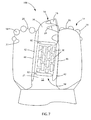
- a conventional fixed-cutting element rotary drill bit 10 includes a bit body 12 that has generally radially projecting and longitudinally extending wings or blades 14 , which are separated by junk slots 16 .
- a plurality of PDC cutting elements 18 are provided on the face 20 of the blades 14 extending over face 20 of the bit body 12 .
- the face 20 of the bit body 12 includes the surfaces of the blades 14 that are configured to engage the formation being drilled, as well as the exterior surfaces of the bit body 12 within the channels and junk slots 16 .
- the plurality of PDC cutting elements 18 may also be provided along each of the blades 14 within pockets 22 formed in the blades 14 , and may be supported from behind by buttresses 24 , which may be integrally formed with the bit body 12 .
- the drill bit 10 may further include an API threaded connection portion 30 for attaching the drill bit 10 to a drill string (not shown). Furthermore, a longitudinal bore (not shown) extends longitudinally through at least a portion of the bit body 12 , and internal fluid passageways (not shown) provide fluid communication between the longitudinal bore and nozzles 32 provided at the face 20 of the bit body 12 and opening onto the channels leading to junk slots 16 .
- the drill bit 10 is positioned at the bottom of a wellbore and rotated while drilling fluid is pumped through the longitudinal bore, the internal fluid passageways, and the nozzles 32 to the face 20 of the bit body 12 .
- the PDC cutting elements 18 scrape across and shear away the underlying earth formation.
- the formation cuttings mix with and are suspended within the drilling fluid and pass through the junk slots 16 and up through an annular space between the wall of the borehole and an outer surface of the drill string to the surface of the earth formation.
- the present invention includes earth-boring tools having wear-resistant material disposed in one or more recesses extending into a body from an exterior surface. Exposed surfaces of the wear-resistant material may be substantially level with the exterior surface of the bit body adjacent the wear-resistant material.
- the one or more recesses may extend along an edge defined by an intersection between exterior surfaces of the body, adjacent one or more wear-resistant inserts in the body, and/or adjacent one or more cutting elements affixed to the body.
- the present invention includes methods of forming earth-boring tools.
- the methods include providing wear-resistant material in at least one recess in an exterior surface of a bit body, and causing exposed surfaces of the wear-resistant material to be substantially level with the exterior surface of the bit body adjacent the wear-resistant material.
- FIG. 1 is a perspective view of an exemplary fixed-cutting element earth-boring rotary drill bit
- FIG. 2 is a side view of another fixed-cutting element earth-boring rotary drill bit illustrating generally longitudinally extending recesses formed in a blade of the drill bit for receiving abrasive wear-resistant material therein;
- FIG. 3 is a partial cross-sectional side view of one blade of the drill bit shown in FIG. 2 illustrating the various portions thereof;
- FIG. 4 is a cross-sectional view of a blade of the drill bit illustrated in FIG. 2 , taken generally perpendicular to the longitudinal axis of the drill bit, further illustrating the recesses formed in the blade for receiving abrasive wear-resistant material therein;
- FIG. 5 is a cross-sectional view of the blade of the drill bit illustrated in FIG. 2 similar to that shown in FIG. 4 , and further illustrating abrasive wear-resistant material disposed in the recesses previously provided in the blade;
- FIG. 6 is a side view of another fixed-cutting element earth-boring rotary drill bit, similar to that shown in FIG. 2 , illustrating generally circumferentially extending recesses formed in a blade of the drill bit for receiving abrasive wear-resistant material therein;
- FIG. 7 is a side view of yet another fixed-cutting element earth-boring rotary drill bit, similar to those shown in FIGS. 2 and 6 , illustrating both generally longitudinally extending recesses and generally circumferentially extending recesses formed in a blade of the drill bit for receiving abrasive wear-resistant material therein;
- FIG. 8 is a cross-sectional view, similar to those shown in FIGS. 4 and 5 , illustrating recesses formed generally around a periphery of a wear-resistant insert provided in a formation-engaging surface of a blade of an earth-boring rotary drill bit for receiving abrasive wear-resistant material therein;
- FIG. 9 is a perspective view of a cutting element secured to a blade of an earth-boring rotary drill bit and illustrating recesses formed generally around a periphery of the cutting element for receiving abrasive wear-resistant material therein;
- FIG. 10 is a cross-sectional view of a portion of the cutting element and blade shown in FIG. 9 , taken generally perpendicular to the longitudinal axis of the cutting element, further illustrating the recesses formed generally around the periphery of the cutting element;
- FIG. 11 is another cross-sectional view of a portion of the cutting element and blade shown in FIG. 9 , taken generally parallel to the longitudinal axis of the cutting element, further illustrating the recesses formed generally around the periphery of the cutting element;
- FIG. 12 is a perspective view of the cutting element and blade shown in FIG. 9 and further illustrating abrasive wear-resistant material disposed in the recesses provided around the periphery of the cutting element;
- FIG. 13 is a cross-sectional view of the cutting element and blade similar to that shown in FIG. 10 and further illustrating the abrasive wear-resistant material provided in the recesses around the periphery of the cutting element;
- FIG. 14 is a cross-sectional view of the cutting element and blade similar to that shown in FIG. 11 and further illustrating the abrasive wear-resistant material provided in the recesses formed around the periphery of the cutting element;
- FIG. 15 is an end view of yet another fixed-cutting element earth-boring rotary drill bit generally illustrating recesses formed in nose and cone regions of blades of the drill bit for receiving abrasive wear-resistant material therein.
- the present invention may be used to enhance the wear resistance of earth-boring rotary drill bits.
- An embodiment of an earth-boring rotary drill bit 40 of the present invention is shown in FIG. 2 .
- the drill bit 40 is generally similar to the drill bit 10 previously described with reference to FIG. 1 , and includes a plurality of blades 14 separated by junk slots 16 .
- FIG. 3 is a partial cross-sectional side view of one blade 14 of the drill bit 10 shown in FIG. 2 .
- each of the blades 14 may include a cone region 50 (a region having the shape of an inverted cone), a nose region 52 , a flank region 54 , a shoulder region 56 , and a gage region 58 (the flank region 54 and the shoulder region 56 may be collectively referred to in the art as either the “flank” or the “shoulder” of the blade).
- the blades 14 may not include a cone region 50 .
- Each of these regions includes an exposed outer surface that is configured to engage the subterranean formation within the wellbore during drilling.
- the cone region 50 , nose region 52 and flank region 54 are configured to engage the formation surfaces at the bottom of the wellbore and to support the majority of the weight-on-bit (WOB). These regions carry a majority of the cutting elements 18 for cutting or scraping away the underlying formation at the bottom of the wellbore.
- the shoulder region 56 and the gage region 58 are configured to engage the formation surfaces on the lateral sides of the wellbore.
- the material of the blades 14 has a tendency to wear away at the formation-engaging surfaces. This wearing away of the material of the blades 14 at the formation-engaging surfaces can lead to loss of cutting elements and/or bit instability (e.g., bit whirl), which may further lead to catastrophic failure of the drill bit 40 .
- various wear-resistant structures and materials have been placed on and/or in these exposed outer surfaces of the blades 14 .
- inserts such as bricks, studs, and wear knots formed from abrasive wear-resistant materials, such as, for example, tungsten carbide, have been inset in formation-engaging surfaces of blades 14 .
- a plurality of wear-resistant inserts 26 may be inset within the blade 14 at the formation-engaging surface 21 of the blade 14 in the gage region 58 thereof.
- the blades 14 may include wear-resistant structures on or in formation-engaging surfaces of other regions of the blades 14 , including the cone region 50 , nose region 52 , flank region 54 , and shoulder region 56 ( FIG. 3 ).
- abrasive wear-resistant inserts may be provided on or in the formation-engaging surfaces of at least one of the cone region 50 and the nose region 52 of the blades rotationally behind one or more cutting elements 18 .
- abrasive wear-resistant material i.e., hardfacing material
- abrasive wear-resistant material also may be applied at selected locations on the formation-engaging surfaces of the blades 14 .
- an oxyacetylene torch or an arc welder for example, may be used to at least partially melt a wear-resistant material, and the molten wear-resistant material may be applied to the formation-engaging surfaces of the blades 14 and allowed to cool and solidify.
- recesses may be formed in one or more formation-engaging surfaces of the drill bit 40 , and the recesses may be filled with wear-resistant material.
- recesses 42 for receiving abrasive wear-resistant material therein may be formed in the blades 14 , as shown in FIG. 2 .
- the recesses 42 may extend generally longitudinally along one or more of the blades 14 .
- a longitudinally extending recess 42 may be formed or otherwise provided along, or proximate to, the edge defined by the intersection between the formation-engaging surface 21 and the rotationally leading surface 46 of one or more of the blades 14 .
- a longitudinally extending recess 42 may be formed or otherwise provided along, or proximate to, the edge defined by the intersection between the formation-engaging surface 21 and the rotationally trailing surface 48 of the blade 14 .
- one or more of the recesses 42 may extend along the blade 14 adjacent (e.g., rotationally forward and rotationally behind) to one or more wear-resistant inserts 26 , as also shown in FIG. 2 .
- FIG. 4 is a cross-sectional view of the blade 14 shown in FIG. 2 taken along section line 4 - 4 shown therein.
- the recesses 42 may have a generally semicircular cross-sectional shape. In additional embodiments, however, the recesses 42 may have any cross-sectional shape such as, for example, generally triangular, generally rectangular (e.g., square), or any other shape.
- the manner in which the recesses 42 are formed or otherwise provided in the blades 14 may depend on the material from which the blades 14 have been formed.
- the recesses 42 may be formed in the blades 14 using, for example, a standard milling machine or other standard machining tool (including hand-held machining tools).
- the recesses 42 may be provided in the blades 14 during formation of the blades 14 .
- Bit bodies 12 of drill bits that comprise particle-matrix composite materials are conventionally formed by casting the bit bodies 12 in a mold.
- inserts or displacements comprising a ceramic or other refractory material and having shapes corresponding to the desired shapes of the recesses to be formed in the bit body 12 may be provided at selected locations within the mold that correspond to the selected locations in the bit body 12 at which the recesses are to be formed. After casting or otherwise forming a bit body 12 around the inserts or displacements within a mold, the bit body 12 may be removed from the mold and the inserts or displacements removed from the bit body 12 to form the recesses 42 .
- recesses 42 may be formed in bit bodies 12 comprising particle-matrix composite materials using ultrasonic machining techniques, which may include applying ultrasonic vibrations to a machining tool as the machining tool is used to form the recesses 42 in a bit body 12 .
- the present invention is not limited by the manner in which the recesses 42 are formed in the blades 14 of the bit body 12 of the drill bit 40 , and any method that can be used to form the recesses 42 in a particular drill bit 40 may be used to provide drill bits that embody teachings of the present invention.
- abrasive wear-resistant material 60 may be provided in the recesses 42 after the recesses 42 have been formed in the formation-engaging surfaces of the blades 14 .
- the exposed exterior surfaces of the abrasive wear-resistant material 60 provided in the recesses 42 may be substantially coextensive with the adjacent exposed exterior surfaces of the blades 14 . In other words, the abrasive wear-resistant material 60 may not project significantly outward from the surface of the blades 14 .
- the topography of the exterior surface of the blades 14 after filling the recesses 42 with the abrasive wear-resistant material 60 may be substantially similar to the topography of the exterior surface of the blades 14 prior to forming the recesses 42 .
- the exposed surfaces of the abrasive wear-resistant material 60 may be substantially level with the surface of the blade 14 adjacent the abrasive wear-resistant material 60 in a direction generally perpendicular to the surface of the blade 14 adjacent the abrasive wear-resistant material 60 .
- the forces applied to the exterior surfaces of the blades 14 may be more evenly distributed across the blades 14 in a manner intended by the bit designer by substantially maintaining the original topography of the exterior surfaces of the blades 14 , as discussed above.
- increased localized stresses may develop within the blades 14 in the areas proximate any abrasive wear-resistant material 60 that projects from the exterior surfaces of the blades 14 as the formation engages such projections of abrasive wear-resistant material 60 .
- the magnitude of such increased localized stresses may be generally proportional to the distance by which the projections extend from the surface of the blades 14 in the direction toward the formation being drilled.
- Such increased localized stresses may be reduced or eliminated by configuring the exposed exterior surfaces of the abrasive wear-resistant material 60 to substantially match the exposed exterior surfaces of the blades 14 prior to forming the recesses 42 , which may lead to decreased wear and increased service life of the drill bit 40 .
- the recesses 42 previously described herein in relation to FIGS. 2 , 4 , and 5 extend in a generally longitudinal direction relative to the drill bit 40 . Furthermore, the recesses 42 are shown therein as being located generally in the gage region of the blades 14 of the bit 40 and extending along the edges defined between the intersections between the formation-engaging surfaces 21 of the blades 14 and the rotationally leading surfaces 46 and the rotationally trailing surfaces 48 of the blades 14 .
- the present invention is not so limited, and recesses filled with abrasive wear-resistant material may be provided in any region of a bit body of a drill bit (including any region of a blade 14 , as well as regions that are not on blades 14 ), according to the present invention.
- recesses 42 filled with abrasive wear-resistant material 60 may have any shape and any orientation in embodiments of drill bits according to the present invention.
- FIG. 6 illustrates another embodiment of a drill bit 90 of the present invention.
- the drill bit 90 is generally similar to the drill bit 40 as previously described with reference to FIG. 2 , and includes a plurality of blades 14 separated by junk slots 16 .
- a plurality of wear-resistant inserts 26 are inset within the formation-engaging surface 21 of each blade 14 in the gage region 58 thereof.
- the drill bit 90 further includes a plurality of recesses 92 formed adjacent the region of each blade 14 comprising the plurality of wear-resistant inserts 26 .
- the recesses 92 may be generally similar to the recesses 42 previously described herein in relation to FIGS. 2 , 4 , and 5 .
- the recesses 92 extend generally circumferentially around the drill bit 90 in a direction generally parallel to the direction of rotation of the drill bit 90 during drilling.
- FIG. 7 illustrates yet another embodiment of a drill bit 100 of the present invention.
- the drill bit 100 is generally similar to the drill bit 40 and the drill bit 90 and includes a plurality of blades 14 , junk slots 16 , and wear-resistant inserts 26 inset within the formation-engaging surface 21 of each blade 14 in the gage region 58 thereof.
- the drill bit 100 includes both generally longitudinally extending recesses 42 (like those of the drill bit 40 ) and generally circumferentially extending recesses 92 (like those of the drill bit 90 ).
- each plurality of wear-resistant inserts 26 may be substantially peripherally surrounded by recesses 42 , 92 that are filled with abrasive wear-resistant material 60 ( FIG.
- the regions of the blades 14 comprising a plurality of wear-resistant inserts 26 are substantially peripherally surrounded by recesses 42 , 92 that may be filled with abrasive wear-resistant material 60 ( FIG. 5 ).
- one or more wear-resistant inserts 26 of a drill bit may be individually substantially peripherally surrounded by recesses (like the recesses 42 , 92 ) filled with abrasive wear-resistant material 60 .
- FIG. 8 is a cross-sectional view of a blade 14 of another embodiment of a drill bit of the present invention.
- the cross-sectional view is similar to the cross-sectional views shown in FIGS. 4 and 5 .
- the blade 14 shown in FIG. 8 includes a wear-resistant insert 26 that is individually substantially peripherally surrounded by recesses 110 that are filled with abrasive wear-resistant material 60 .
- the recesses 110 may be substantially similar to the previously described recesses 42 , 92 and may be filled with abrasive wear-resistant material 60 .
- the exposed exterior surfaces of the wear-resistant insert 26 , abrasive wear-resistant material 60 , and regions of the blade 14 adjacent the abrasive wear-resistant material 60 may be generally coextensive and planar to reduce or eliminate localized stress concentration caused by any abrasive wear-resistant material 60 projecting from the blade 14 generally toward a formation being drilled.
- the abrasive wear-resistant material 60 terminates at edges defined by intersections between at least one surface defining the recess, the first exterior surface, and the second exterior surface.
- FIG. 9 is a perspective view of one cutting element 18 secured within a cutting element pocket 22 on a blade 14 of a drill bit similar to each of the previously described drill bits.
- recesses 114 may be formed in the blade 14 that substantially peripherally surround the cutting element 18 .
- the recesses 114 may have a cross-sectional shape that is generally triangular, although, in additional embodiments, the recesses 114 may have any other shape.
- the cutting element 18 may be secured within the cutting element pocket 22 using a bonding material 116 such as, for example, an adhesive or a brazing alloy, which may be provided at an interface and used to secure and attach the cutting element 18 to the blade 14 .
- FIGS. 12-14 are substantially similar to FIGS. 9-11 , respectively, but further illustrate abrasive wear-resistant material 60 disposed within the recesses 114 provided in the blade 14 of a bit body around the cutting element 18 .
- the exposed exterior surfaces of the abrasive wear-resistant material 60 and the regions of the blade 14 adjacent the abrasive wear-resistant material 60 may be generally coextensive.
- abrasive wear-resistant material 60 may be configured so as not to extend beyond the adjacent surfaces of the blade 14 to reduce or eliminate localized stress concentration caused by any abrasive wear-resistant material 60 projecting from the blade 14 generally towards a formation being drilled.
- the abrasive wear-resistant material 60 may cover and protect at least a portion of the bonding material 24 used to secure the cutting element 18 within the cutting element pocket 22 , which may protect the bonding material 24 from wear during drilling. By protecting the bonding material 24 from wear during drilling, the abrasive wear-resistant material 60 may help to prevent separation of the cutting element 18 from the blade 14 , damage to the bit body, and catastrophic failure of the drill bit.
- FIG. 15 is an end view illustrating the face of yet another embodiment of an earth-boring rotary drill bit 120 of the present invention.
- recesses 122 for receiving abrasive wear-resistant material 60 therein may be provided between cutting elements 18 .
- the recesses 122 may extend generally circumferentially about a longitudinal axis of the bit (not shown) between cutting elements 18 positioned in at least one of a cone region 50 ( FIG. 3 ) and a nose region 52 ( FIG. 3 ) of the drill bit 120 .
- recesses 124 may be provided rotationally behind cutting elements 18 .
- the recesses 124 may extend generally longitudinally along a blade 14 rotationally behind one or more cutting elements 18 positioned in at least one of the cone region 50 ( FIG. 3 ) and the nose region 52 ( FIG. 3 ) of the drill bit 120 .
- the recesses 124 may not be elongated and may have a generally circular or a generally rectangular shape. Such recesses 124 may be positioned directly rotationally behind one or more cutting elements 18 , or rotationally behind adjacent cutting elements 18 , but at a radial position (measured from the longitudinal axis of the drill bit 120 ) between the adjacent cutting elements 18 .
- the abrasive wear-resistant materials 60 described herein may include, for example, a particle-matrix composite material comprising a plurality of hard phase regions or particles dispersed throughout a matrix material.
- the hard ceramic phase regions or particles may comprise, for example, diamond or carbides, nitrides, oxides, and borides (including boron carbide (B 4 C)).
- the hard ceramic phase regions or particles may comprise, for example, carbides and borides made from elements such as W, Ti, Mo, Nb, V, Hf, Ta, Cr, Zr, Al, and Si.
- materials that may be used to form hard phase regions or particles include tungsten carbide (WC), titanium carbide (TiC), tantalum carbide (TaC), titanium diboride (TiB 2 ), chromium carbides, titanium nitride (TiN), aluminum oxide (Al 2 O 3 ), aluminum nitride (AlN), and silicon carbide (SiC).
- the metal matrix material of the ceramic-metal composite material may include, for example, cobalt-based, iron-based, nickel-based, iron- and nickel-based, cobalt- and nickel-based, iron- and cobalt-based, aluminum-based, copper-based, magnesium-based, and titanium-based alloys.
- the matrix material may also be selected from commercially pure elements such as, for example, cobalt, aluminum, copper, magnesium, titanium, iron, and nickel.
- bit body encompasses bodies of earth-boring rotary drill bits (including fixed cutter-type bits and roller cone-type bits), as well as bodies of other earth-boring tools including, but not limited to, core bits, bi-center bits, eccentric bits, reamers, underreamers, and other drilling and downhole tools.
Abstract
Description
Claims (6)
Priority Applications (1)
| Application Number | Priority Date | Filing Date | Title |
|---|---|---|---|
| US11/864,482 US8104550B2 (en) | 2006-08-30 | 2007-09-28 | Methods for applying wear-resistant material to exterior surfaces of earth-boring tools and resulting structures |
Applications Claiming Priority (3)
| Application Number | Priority Date | Filing Date | Title |
|---|---|---|---|
| US11/513,677 US7703555B2 (en) | 2005-09-09 | 2006-08-30 | Drilling tools having hardfacing with nickel-based matrix materials and hard particles |
| US84815406P | 2006-09-29 | 2006-09-29 | |
| US11/864,482 US8104550B2 (en) | 2006-08-30 | 2007-09-28 | Methods for applying wear-resistant material to exterior surfaces of earth-boring tools and resulting structures |
Related Parent Applications (1)
| Application Number | Title | Priority Date | Filing Date |
|---|---|---|---|
| US11/513,677 Continuation-In-Part US7703555B2 (en) | 2005-09-09 | 2006-08-30 | Drilling tools having hardfacing with nickel-based matrix materials and hard particles |
Publications (2)
| Publication Number | Publication Date |
|---|---|
| US20080083568A1 US20080083568A1 (en) | 2008-04-10 |
| US8104550B2 true US8104550B2 (en) | 2012-01-31 |
Family
ID=38857907
Family Applications (1)
| Application Number | Title | Priority Date | Filing Date |
|---|---|---|---|
| US11/864,482 Active 2027-01-26 US8104550B2 (en) | 2006-08-30 | 2007-09-28 | Methods for applying wear-resistant material to exterior surfaces of earth-boring tools and resulting structures |
Country Status (5)
| Country | Link |
|---|---|
| US (1) | US8104550B2 (en) |
| EP (1) | EP2066864A1 (en) |
| CA (1) | CA2662966C (en) |
| RU (1) | RU2009111383A (en) |
| WO (1) | WO2008027484A1 (en) |
Families Citing this family (16)
| Publication number | Priority date | Publication date | Assignee | Title |
|---|---|---|---|---|
| US8002052B2 (en) * | 2005-09-09 | 2011-08-23 | Baker Hughes Incorporated | Particle-matrix composite drill bits with hardfacing |
| US7597159B2 (en) * | 2005-09-09 | 2009-10-06 | Baker Hughes Incorporated | Drill bits and drilling tools including abrasive wear-resistant materials |
| US7997359B2 (en) | 2005-09-09 | 2011-08-16 | Baker Hughes Incorporated | Abrasive wear-resistant hardfacing materials, drill bits and drilling tools including abrasive wear-resistant hardfacing materials |
| US7703555B2 (en) | 2005-09-09 | 2010-04-27 | Baker Hughes Incorporated | Drilling tools having hardfacing with nickel-based matrix materials and hard particles |
| US20100193253A1 (en) * | 2009-01-30 | 2010-08-05 | Massey Alan J | Earth-boring tools and bodies of such tools including nozzle recesses, and methods of forming same |
| WO2010108178A1 (en) * | 2009-03-20 | 2010-09-23 | Smith International, Inc. | Hardfacing compositions, methods of applying the hardfacing compositions, and tools using such hardfacing compositions |
| US8079428B2 (en) | 2009-07-02 | 2011-12-20 | Baker Hughes Incorporated | Hardfacing materials including PCD particles, welding rods and earth-boring tools including such materials, and methods of forming and using same |
| SA111320374B1 (en) | 2010-04-14 | 2015-08-10 | بيكر هوغيس انكوبوريتد | Method Of Forming Polycrystalline Diamond From Derivatized Nanodiamond |
| GB201009661D0 (en) * | 2010-06-09 | 2010-07-21 | 2Td Ltd | Cutting assembly |
| EP2668362B1 (en) | 2011-01-28 | 2020-01-01 | Baker Hughes, a GE company, LLC | Non-magnetic drill string member with non-magnetic hardfacing and method of making the same |
| CA2892224A1 (en) | 2012-12-28 | 2014-07-03 | Varel International Ind., L.P. | Streamlined pocket design for pdc drill bits |
| US9140072B2 (en) | 2013-02-28 | 2015-09-22 | Baker Hughes Incorporated | Cutting elements including non-planar interfaces, earth-boring tools including such cutting elements, and methods of forming cutting elements |
| CN103526101A (en) * | 2013-09-27 | 2014-01-22 | 无锡阳工机械制造有限公司 | Metal cutting tool and preparation method thereof |
| WO2015157710A1 (en) | 2014-04-10 | 2015-10-15 | Varel International Ind., L.P. | Ultra-high rop blade enhancement |
| CA2969232C (en) * | 2014-12-30 | 2019-06-11 | Halliburton Energy Services, Inc. | Downhole tool surfaces configured to reduce drag forces and erosion during exposure to fluid flow |
| US10386801B2 (en) * | 2015-08-03 | 2019-08-20 | Baker Hughes, A Ge Company, Llc | Methods of forming and methods of repairing earth-boring tools |
Citations (254)
| Publication number | Priority date | Publication date | Assignee | Title |
|---|---|---|---|---|
| US2033594A (en) | 1931-09-24 | 1936-03-10 | Stoody Co | Scarifier tooth |
| US2407642A (en) | 1945-11-23 | 1946-09-17 | Hughes Tool Co | Method of treating cutter teeth |
| US2660405A (en) | 1947-07-11 | 1953-11-24 | Hughes Tool Co | Cutting tool and method of making |
| US2740651A (en) * | 1951-03-10 | 1956-04-03 | Exxon Research Engineering Co | Resiliently coupled drill bit |
| US2819958A (en) | 1955-08-16 | 1958-01-14 | Mallory Sharon Titanium Corp | Titanium base alloys |
| US2819959A (en) | 1956-06-19 | 1958-01-14 | Mallory Sharon Titanium Corp | Titanium base vanadium-iron-aluminum alloys |
| US2906654A (en) | 1954-09-23 | 1959-09-29 | Abkowitz Stanley | Heat treated titanium-aluminumvanadium alloy |
| US2961312A (en) | 1959-05-12 | 1960-11-22 | Union Carbide Corp | Cobalt-base alloy suitable for spray hard-facing deposit |
| GB945227A (en) | 1961-09-06 | 1963-12-23 | Jersey Prod Res Co | Process for making hard surfacing material |
| US3158214A (en) | 1962-03-15 | 1964-11-24 | Hughes Tool Co | Shirttail hardfacing |
| US3180440A (en) * | 1962-12-31 | 1965-04-27 | Jersey Prod Res Co | Drag bit |
| US3260579A (en) | 1962-02-14 | 1966-07-12 | Hughes Tool Co | Hardfacing structure |
| GB1070039A (en) | 1963-11-07 | 1967-05-24 | Eutectic Welding Alloys | Improved heterogeneous facing composition |
| US3368881A (en) | 1965-04-12 | 1968-02-13 | Nuclear Metals Division Of Tex | Titanium bi-alloy composites and manufacture thereof |
| US3471921A (en) | 1965-12-23 | 1969-10-14 | Shell Oil Co | Method of connecting a steel blank to a tungsten bit body |
| US3660050A (en) | 1969-06-23 | 1972-05-02 | Du Pont | Heterogeneous cobalt-bonded tungsten carbide |
| US3727704A (en) * | 1971-03-17 | 1973-04-17 | Christensen Diamond Prod Co | Diamond drill bit |
| US3757879A (en) | 1972-08-24 | 1973-09-11 | Christensen Diamond Prod Co | Drill bits and methods of producing drill bits |
| US3768984A (en) | 1972-04-03 | 1973-10-30 | Buell E | Welding rods |
| US3790353A (en) | 1972-02-22 | 1974-02-05 | Servco Co Division Smith Int I | Hard-facing article |
| US3800891A (en) | 1968-04-18 | 1974-04-02 | Hughes Tool Co | Hardfacing compositions and gage hardfacing on rolling cutter rock bits |
| US3942954A (en) | 1970-01-05 | 1976-03-09 | Deutsche Edelstahlwerke Aktiengesellschaft | Sintering steel-bonded carbide hard alloy |
| US3987859A (en) | 1973-10-24 | 1976-10-26 | Dresser Industries, Inc. | Unitized rotary rock bit |
| US3989554A (en) | 1973-06-18 | 1976-11-02 | Hughes Tool Company | Composite hardfacing of air hardening steel and particles of tungsten carbide |
| US4017480A (en) | 1974-08-20 | 1977-04-12 | Permanence Corporation | High density composite structure of hard metallic material in a matrix |
| US4043611A (en) | 1976-02-27 | 1977-08-23 | Reed Tool Company | Hard surfaced well tool and method of making same |
| US4047828A (en) | 1976-03-31 | 1977-09-13 | Makely Joseph E | Core drill |
| US4059217A (en) | 1975-12-30 | 1977-11-22 | Rohr Industries, Incorporated | Superalloy liquid interface diffusion bonding |
| US4094709A (en) | 1977-02-10 | 1978-06-13 | Kelsey-Hayes Company | Method of forming and subsequently heat treating articles of near net shaped from powder metal |
| US4128136A (en) | 1977-12-09 | 1978-12-05 | Lamage Limited | Drill bit |
| US4173457A (en) | 1978-03-23 | 1979-11-06 | Alloys, Incorporated | Hardfacing composition of nickel-bonded sintered chromium carbide particles and tools hardfaced thereof |
| US4198233A (en) | 1977-05-17 | 1980-04-15 | Thyssen Edelstahlwerke Ag | Method for the manufacture of tools, machines or parts thereof by composite sintering |
| US4221270A (en) | 1978-12-18 | 1980-09-09 | Smith International, Inc. | Drag bit |
| US4229638A (en) | 1975-04-01 | 1980-10-21 | Dresser Industries, Inc. | Unitized rotary rock bit |
| US4233720A (en) | 1978-11-30 | 1980-11-18 | Kelsey-Hayes Company | Method of forming and ultrasonic testing articles of near net shape from powder metal |
| US4243727A (en) | 1977-04-25 | 1981-01-06 | Hughes Tool Company | Surface smoothed tool joint hardfacing |
| US4252202A (en) | 1979-08-06 | 1981-02-24 | Purser Sr James A | Drill bit |
| US4255165A (en) | 1978-12-22 | 1981-03-10 | General Electric Company | Composite compact of interleaved polycrystalline particles and cemented carbide masses |
| US4262761A (en) | 1979-10-05 | 1981-04-21 | Dresser Industries, Inc. | Long-life milled tooth cutting structure |
| US4306139A (en) | 1978-12-28 | 1981-12-15 | Ishikawajima-Harima Jukogyo Kabushiki Kaisha | Method for welding hard metal |
| US4341557A (en) | 1979-09-10 | 1982-07-27 | Kelsey-Hayes Company | Method of hot consolidating powder with a recyclable container material |
| GB2104101A (en) | 1980-12-05 | 1983-03-02 | Castolin Sa | Material allowing the stratification of machining parts the latter having then an improved resistance to abrasion and hammering |
| US4389952A (en) | 1980-06-30 | 1983-06-28 | Fritz Gegauf Aktiengesellschaft Bernina-Machmaschinenfabrik | Needle bar operated trimmer |
| US4398952A (en) | 1980-09-10 | 1983-08-16 | Reed Rock Bit Company | Methods of manufacturing gradient composite metallic structures |
| US4414029A (en) | 1981-05-20 | 1983-11-08 | Kennametal Inc. | Powder mixtures for wear resistant facings and products produced therefrom |
| US4455278A (en) | 1980-12-02 | 1984-06-19 | Skf Industrial Trading & Development Company, B.V. | Method for producing an object on which an exterior layer is applied by thermal spraying and object, in particular a drill bit, obtained pursuant to this method |
| US4499048A (en) | 1983-02-23 | 1985-02-12 | Metal Alloys, Inc. | Method of consolidating a metallic body |
| US4499795A (en) | 1983-09-23 | 1985-02-19 | Strata Bit Corporation | Method of drill bit manufacture |
| US4499958A (en) | 1983-04-29 | 1985-02-19 | Strata Bit Corporation | Drag blade bit with diamond cutting elements |
| US4526748A (en) | 1980-05-22 | 1985-07-02 | Kelsey-Hayes Company | Hot consolidation of powder metal-floating shaping inserts |
| US4547337A (en) | 1982-04-28 | 1985-10-15 | Kelsey-Hayes Company | Pressure-transmitting medium and method for utilizing same to densify material |
| US4552232A (en) | 1984-06-29 | 1985-11-12 | Spiral Drilling Systems, Inc. | Drill-bit with full offset cutter bodies |
| US4554130A (en) | 1984-10-01 | 1985-11-19 | Cdp, Ltd. | Consolidation of a part from separate metallic components |
| US4562892A (en) | 1984-07-23 | 1986-01-07 | Cdp, Ltd. | Rolling cutters for drill bits |
| US4562990A (en) | 1983-06-06 | 1986-01-07 | Rose Robert H | Die venting apparatus in molding of thermoset plastic compounds |
| US4579713A (en) | 1985-04-25 | 1986-04-01 | Ultra-Temp Corporation | Method for carbon control of carbide preforms |
| US4596694A (en) | 1982-09-20 | 1986-06-24 | Kelsey-Hayes Company | Method for hot consolidating materials |
| US4597730A (en) | 1982-09-20 | 1986-07-01 | Kelsey-Hayes Company | Assembly for hot consolidating materials |
| US4597456A (en) | 1984-07-23 | 1986-07-01 | Cdp, Ltd. | Conical cutters for drill bits, and processes to produce same |
| US4611673A (en) | 1980-03-24 | 1986-09-16 | Reed Rock Bit Company | Drill bit having offset roller cutters and improved nozzles |
| US4630693A (en) | 1985-04-15 | 1986-12-23 | Goodfellow Robert D | Rotary cutter assembly |
| US4630692A (en) | 1984-07-23 | 1986-12-23 | Cdp, Ltd. | Consolidation of a drilling element from separate metallic components |
| US4656002A (en) | 1985-10-03 | 1987-04-07 | Roc-Tec, Inc. | Self-sealing fluid die |
| US4666797A (en) | 1981-05-20 | 1987-05-19 | Kennametal Inc. | Wear resistant facings for couplings |
| US4667756A (en) | 1986-05-23 | 1987-05-26 | Hughes Tool Company-Usa | Matrix bit with extended blades |
| US4674802A (en) | 1982-09-17 | 1987-06-23 | Kennametal, Inc | Multi-insert cutter bit |
| US4676124A (en) | 1986-07-08 | 1987-06-30 | Dresser Industries, Inc. | Drag bit with improved cutter mount |
| US4686080A (en) | 1981-11-09 | 1987-08-11 | Sumitomo Electric Industries, Ltd. | Composite compact having a base of a hard-centered alloy in which the base is joined to a substrate through a joint layer and process for producing the same |
| US4694919A (en) | 1985-01-23 | 1987-09-22 | Nl Petroleum Products Limited | Rotary drill bits with nozzle former and method of manufacturing |
| US4726432A (en) | 1987-07-13 | 1988-02-23 | Hughes Tool Company-Usa | Differentially hardfaced rock bit |
| EP0264674A2 (en) | 1986-10-20 | 1988-04-27 | Baker Hughes Incorporated | Low pressure bonding of PCD bodies and method |
| US4743515A (en) | 1984-11-13 | 1988-05-10 | Santrade Limited | Cemented carbide body used preferably for rock drilling and mineral cutting |
| US4744943A (en) | 1986-12-08 | 1988-05-17 | The Dow Chemical Company | Process for the densification of material preforms |
| US4762028A (en) | 1986-05-10 | 1988-08-09 | Nl Petroleum Products Limited | Rotary drill bits |
| GB2203774A (en) | 1987-04-21 | 1988-10-26 | Cledisc Int Bv | Rotary drilling device |
| US4781770A (en) | 1986-03-24 | 1988-11-01 | Smith International, Inc. | Process for laser hardfacing drill bit cones having hard cutter inserts |
| US4809903A (en) | 1986-11-26 | 1989-03-07 | United States Of America As Represented By The Secretary Of The Air Force | Method to produce metal matrix composite articles from rich metastable-beta titanium alloys |
| US4814234A (en) | 1987-03-25 | 1989-03-21 | Dresser Industries | Surface protection method and article formed thereby |
| US4836307A (en) | 1987-12-29 | 1989-06-06 | Smith International, Inc. | Hard facing for milled tooth rock bits |
| US4838366A (en) | 1988-08-30 | 1989-06-13 | Jones A Raymond | Drill bit |
| US4871377A (en) | 1986-07-30 | 1989-10-03 | Frushour Robert H | Composite abrasive compact having high thermal stability and transverse rupture strength |
| US4884477A (en) | 1988-03-31 | 1989-12-05 | Eastman Christensen Company | Rotary drill bit with abrasion and erosion resistant facing |
| US4889017A (en) | 1984-07-19 | 1989-12-26 | Reed Tool Co., Ltd. | Rotary drill bit for use in drilling holes in subsurface earth formations |
| US4919013A (en) | 1988-09-14 | 1990-04-24 | Eastman Christensen Company | Preformed elements for a rotary drill bit |
| US4923512A (en) | 1989-04-07 | 1990-05-08 | The Dow Chemical Company | Cobalt-bound tungsten carbide metal matrix composites and cutting tools formed therefrom |
| US4933240A (en) | 1985-12-27 | 1990-06-12 | Barber Jr William R | Wear-resistant carbide surfaces |
| US4938991A (en) | 1987-03-25 | 1990-07-03 | Dresser Industries, Inc. | Surface protection method and article formed thereby |
| US4944774A (en) | 1987-12-29 | 1990-07-31 | Smith International, Inc. | Hard facing for milled tooth rock bits |
| US4956012A (en) | 1988-10-03 | 1990-09-11 | Newcomer Products, Inc. | Dispersion alloyed hard metal composites |
| US4968348A (en) | 1988-07-29 | 1990-11-06 | Dynamet Technology, Inc. | Titanium diboride/titanium alloy metal matrix microcomposite material and process for powder metal cladding |
| US5000273A (en) | 1990-01-05 | 1991-03-19 | Norton Company | Low melting point copper-manganese-zinc alloy for infiltration binder in matrix body rock drill bits |
| US5010225A (en) | 1989-09-15 | 1991-04-23 | Grant Tfw | Tool joint and method of hardfacing same |
| US5030598A (en) | 1990-06-22 | 1991-07-09 | Gte Products Corporation | Silicon aluminum oxynitride material containing boron nitride |
| US5032352A (en) | 1990-09-21 | 1991-07-16 | Ceracon, Inc. | Composite body formation of consolidated powder metal part |
| US5038640A (en) | 1990-02-08 | 1991-08-13 | Hughes Tool Company | Titanium carbide modified hardfacing for use on bearing surfaces of earth boring bits |
| US5049450A (en) | 1990-05-10 | 1991-09-17 | The Perkin-Elmer Corporation | Aluminum and boron nitride thermal spray powder |
| US5051112A (en) | 1988-06-29 | 1991-09-24 | Smith International, Inc. | Hard facing |
| EP0453428A1 (en) | 1990-04-20 | 1991-10-23 | Sandvik Aktiebolag | Method of making cemented carbide body for tools and wear parts |
| US5089182A (en) | 1988-10-15 | 1992-02-18 | Eberhard Findeisen | Process of manufacturing cast tungsten carbide spheres |
| US5090491A (en) | 1987-10-13 | 1992-02-25 | Eastman Christensen Company | Earth boring drill bit with matrix displacing material |
| US5101692A (en) | 1989-09-16 | 1992-04-07 | Astec Developments Limited | Drill bit or corehead manufacturing process |
| US5150636A (en) | 1991-06-28 | 1992-09-29 | Loudon Enterprises, Inc. | Rock drill bit and method of making same |
| US5152194A (en) | 1991-04-24 | 1992-10-06 | Smith International, Inc. | Hardfaced mill tooth rotary cone rock bit |
| US5161898A (en) | 1991-07-05 | 1992-11-10 | Camco International Inc. | Aluminide coated bearing elements for roller cutter drill bits |
| US5186267A (en) | 1990-02-14 | 1993-02-16 | Western Rock Bit Company Limited | Journal bearing type rock bit |
| US5232522A (en) | 1991-10-17 | 1993-08-03 | The Dow Chemical Company | Rapid omnidirectional compaction process for producing metal nitride, carbide, or carbonitride coating on ceramic substrate |
| US5242017A (en) | 1991-12-27 | 1993-09-07 | Hailey Charles D | Cutter blades for rotary tubing tools |
| US5250355A (en) | 1991-12-17 | 1993-10-05 | Kennametal Inc. | Arc hardfacing rod |
| US5281260A (en) | 1992-02-28 | 1994-01-25 | Baker Hughes Incorporated | High-strength tungsten carbide material for use in earth-boring bits |
| US5286685A (en) | 1990-10-24 | 1994-02-15 | Savoie Refractaires | Refractory materials consisting of grains bonded by a binding phase based on aluminum nitride containing boron nitride and/or graphite particles and process for their production |
| US5291807A (en) | 1991-03-11 | 1994-03-08 | Dresser Industries, Inc. | Patterned hardfacing shapes on insert cutter cones |
| US5311958A (en) | 1992-09-23 | 1994-05-17 | Baker Hughes Incorporated | Earth-boring bit with an advantageous cutting structure |
| US5328763A (en) | 1993-02-03 | 1994-07-12 | Kennametal Inc. | Spray powder for hardfacing and part with hardfacing |
| US5348806A (en) | 1991-09-21 | 1994-09-20 | Hitachi Metals, Ltd. | Cermet alloy and process for its production |
| US5373907A (en) | 1993-01-26 | 1994-12-20 | Dresser Industries, Inc. | Method and apparatus for manufacturing and inspecting the quality of a matrix body drill bit |
| US5433280A (en) | 1994-03-16 | 1995-07-18 | Baker Hughes Incorporated | Fabrication method for rotary bits and bit components and bits and components produced thereby |
| US5439068A (en) | 1994-08-08 | 1995-08-08 | Dresser Industries, Inc. | Modular rotary drill bit |
| US5443337A (en) | 1993-07-02 | 1995-08-22 | Katayama; Ichiro | Sintered diamond drill bits and method of making |
| US5479997A (en) | 1993-07-08 | 1996-01-02 | Baker Hughes Incorporated | Earth-boring bit with improved cutting structure |
| US5482670A (en) | 1994-05-20 | 1996-01-09 | Hong; Joonpyo | Cemented carbide |
| US5484468A (en) | 1993-02-05 | 1996-01-16 | Sandvik Ab | Cemented carbide with binder phase enriched surface zone and enhanced edge toughness behavior and process for making same |
| US5492186A (en) | 1994-09-30 | 1996-02-20 | Baker Hughes Incorporated | Steel tooth bit with a bi-metallic gage hardfacing |
| US5506055A (en) | 1994-07-08 | 1996-04-09 | Sulzer Metco (Us) Inc. | Boron nitride and aluminum thermal spray powder |
| GB2295157A (en) | 1994-11-21 | 1996-05-22 | Baker Hughes Inc | Improved hardfacing composition for earth-boring bits |
| US5535838A (en) | 1993-03-19 | 1996-07-16 | Smith International, Inc. | High performance overlay for rock drilling bits |
| US5543235A (en) | 1994-04-26 | 1996-08-06 | Sintermet | Multiple grade cemented carbide articles and a method of making the same |
| US5560440A (en) | 1993-02-12 | 1996-10-01 | Baker Hughes Incorporated | Bit for subterranean drilling fabricated from separately-formed major components |
| US5586612A (en) | 1995-01-26 | 1996-12-24 | Baker Hughes Incorporated | Roller cone bit with positive and negative offset and smooth running configuration |
| US5589268A (en) | 1995-02-01 | 1996-12-31 | Kennametal Inc. | Matrix for a hard composite |
| US5593474A (en) | 1988-08-04 | 1997-01-14 | Smith International, Inc. | Composite cemented carbide |
| US5612264A (en) | 1993-04-30 | 1997-03-18 | The Dow Chemical Company | Methods for making WC-containing bodies |
| US5641921A (en) | 1995-08-22 | 1997-06-24 | Dennis Tool Company | Low temperature, low pressure, ductile, bonded cermet for enhanced abrasion and erosion performance |
| US5641251A (en) | 1994-07-14 | 1997-06-24 | Cerasiv Gmbh Innovatives Keramik-Engineering | All-ceramic drill bit |
| US5653299A (en) | 1995-11-17 | 1997-08-05 | Camco International Inc. | Hardmetal facing for rolling cutter drill bit |
| US5662183A (en) | 1995-08-15 | 1997-09-02 | Smith International, Inc. | High strength matrix material for PDC drag bits |
| US5666864A (en) | 1993-12-22 | 1997-09-16 | Tibbitts; Gordon A. | Earth boring drill bit with shell supporting an external drilling surface |
| US5677042A (en) | 1994-12-23 | 1997-10-14 | Kennametal Inc. | Composite cermet articles and method of making |
| US5697046A (en) | 1994-12-23 | 1997-12-09 | Kennametal Inc. | Composite cermet articles and method of making |
| US5697462A (en) | 1995-06-30 | 1997-12-16 | Baker Hughes Inc. | Earth-boring bit having improved cutting structure |
| US5732783A (en) | 1995-01-13 | 1998-03-31 | Camco Drilling Group Limited Of Hycalog | In or relating to rotary drill bits |
| US5740872A (en) | 1996-07-01 | 1998-04-21 | Camco International Inc. | Hardfacing material for rolling cutter drill bits |
| US5753160A (en) | 1994-10-19 | 1998-05-19 | Ngk Insulators, Ltd. | Method for controlling firing shrinkage of ceramic green body |
| US5755298A (en) | 1995-08-03 | 1998-05-26 | Dresser Industries, Inc. | Hardfacing with coated diamond particles |
| US5765095A (en) | 1996-08-19 | 1998-06-09 | Smith International, Inc. | Polycrystalline diamond bit manufacturing |
| US5778301A (en) | 1994-05-20 | 1998-07-07 | Hong; Joonpyo | Cemented carbide |
| US5789686A (en) | 1994-12-23 | 1998-08-04 | Kennametal Inc. | Composite cermet articles and method of making |
| US5791422A (en) | 1996-03-12 | 1998-08-11 | Smith International, Inc. | Rock bit with hardfacing material incorporating spherical cast carbide particles |
| US5791423A (en) | 1996-08-02 | 1998-08-11 | Baker Hughes Incorporated | Earth-boring bit having an improved hard-faced tooth structure |
| AU695583B2 (en) | 1996-08-01 | 1998-08-13 | Smith International, Inc. | Double cemented carbide inserts |
| US5830256A (en) | 1995-05-11 | 1998-11-03 | Northrop; Ian Thomas | Cemented carbide |
| US5856626A (en) | 1995-12-22 | 1999-01-05 | Sandvik Ab | Cemented carbide body with increased wear resistance |
| US5865571A (en) | 1997-06-17 | 1999-02-02 | Norton Company | Non-metallic body cutting tools |
| US5880382A (en) | 1996-08-01 | 1999-03-09 | Smith International, Inc. | Double cemented carbide composites |
| US5893204A (en) | 1996-11-12 | 1999-04-13 | Dresser Industries, Inc. | Production process for casting steel-bodied bits |
| US5896940A (en) | 1997-09-10 | 1999-04-27 | Pietrobelli; Fausto | Underreamer |
| US5897830A (en) | 1996-12-06 | 1999-04-27 | Dynamet Technology | P/M titanium composite casting |
| US5904212A (en) | 1996-11-12 | 1999-05-18 | Dresser Industries, Inc. | Gauge face inlay for bit hardfacing |
| US5921330A (en) | 1997-03-12 | 1999-07-13 | Smith International, Inc. | Rock bit with wear-and fracture-resistant hardfacing |
| US5924502A (en) | 1996-11-12 | 1999-07-20 | Dresser Industries, Inc. | Steel-bodied bit |
| US5954147A (en) | 1997-07-09 | 1999-09-21 | Baker Hughes Incorporated | Earth boring bits with nanocrystalline diamond enhanced elements |
| US5963775A (en) | 1995-12-05 | 1999-10-05 | Smith International, Inc. | Pressure molded powder metal milled tooth rock bit cone |
| US5967248A (en) | 1997-10-14 | 1999-10-19 | Camco International Inc. | Rock bit hardmetal overlay and process of manufacture |
| US6051171A (en) | 1994-10-19 | 2000-04-18 | Ngk Insulators, Ltd. | Method for controlling firing shrinkage of ceramic green body |
| EP0995876A2 (en) | 1998-10-22 | 2000-04-26 | Camco International (UK) Limited | Methods of manufacturing rotary drill bits |
| US6063333A (en) | 1996-10-15 | 2000-05-16 | Penn State Research Foundation | Method and apparatus for fabrication of cobalt alloy composite inserts |
| US6068070A (en) | 1997-09-03 | 2000-05-30 | Baker Hughes Incorporated | Diamond enhanced bearing for earth-boring bit |
| US6073518A (en) | 1996-09-24 | 2000-06-13 | Baker Hughes Incorporated | Bit manufacturing method |
| US6086980A (en) | 1996-12-20 | 2000-07-11 | Sandvik Ab | Metal working drill/endmill blank and its method of manufacture |
| US6099664A (en) | 1993-01-26 | 2000-08-08 | London & Scandinavian Metallurgical Co., Ltd. | Metal matrix alloys |
| US6124564A (en) | 1998-01-23 | 2000-09-26 | Smith International, Inc. | Hardfacing compositions and hardfacing coatings formed by pulsed plasma-transferred arc |
| GB2352727A (en) | 1999-05-11 | 2001-02-07 | Baker Hughes Inc | Hardfacing composition for earth boring bits |
| US6196338B1 (en) | 1998-01-23 | 2001-03-06 | Smith International, Inc. | Hardfacing rock bit cones for erosion protection |
| US6200514B1 (en) | 1999-02-09 | 2001-03-13 | Baker Hughes Incorporated | Process of making a bit body and mold therefor |
| US6206115B1 (en) | 1998-08-21 | 2001-03-27 | Baker Hughes Incorporated | Steel tooth bit with extra-thick hardfacing |
| US6209420B1 (en) | 1994-03-16 | 2001-04-03 | Baker Hughes Incorporated | Method of manufacturing bits, bit components and other articles of manufacture |
| US6214287B1 (en) | 1999-04-06 | 2001-04-10 | Sandvik Ab | Method of making a submicron cemented carbide with increased toughness |
| US6214134B1 (en) | 1995-07-24 | 2001-04-10 | The United States Of America As Represented By The Secretary Of The Air Force | Method to produce high temperature oxidation resistant metal matrix composites by fiber density grading |
| US6220117B1 (en) | 1998-08-18 | 2001-04-24 | Baker Hughes Incorporated | Methods of high temperature infiltration of drill bits and infiltrating binder |
| US6228139B1 (en) | 1999-05-04 | 2001-05-08 | Sandvik Ab | Fine-grained WC-Co cemented carbide |
| US6234261B1 (en) * | 1999-03-18 | 2001-05-22 | Camco International (Uk) Limited | Method of applying a wear-resistant layer to a surface of a downhole component |
| US6241036B1 (en) | 1998-09-16 | 2001-06-05 | Baker Hughes Incorporated | Reinforced abrasive-impregnated cutting elements, drill bits including same |
| US6254658B1 (en) | 1999-02-24 | 2001-07-03 | Mitsubishi Materials Corporation | Cemented carbide cutting tool |
| GB2357788A (en) | 2000-01-03 | 2001-07-04 | Baker Hughes Inc | Overlapping hardface layers for teeth of an earth boring bit |
| US20010015290A1 (en) | 1998-01-23 | 2001-08-23 | Sue J. Albert | Hardfacing rock bit cones for erosion protection |
| US20010017224A1 (en) | 1999-03-18 | 2001-08-30 | Evans Stephen Martin | Method of applying a wear-resistant layer to a surface of a downhole component |
| US6287360B1 (en) | 1998-09-18 | 2001-09-11 | Smith International, Inc. | High-strength matrix body |
| US6290438B1 (en) | 1998-02-19 | 2001-09-18 | August Beck Gmbh & Co. | Reaming tool and process for its production |
| US6293986B1 (en) | 1997-03-10 | 2001-09-25 | Widia Gmbh | Hard metal or cermet sintered body and method for the production thereof |
| US20020004105A1 (en) | 1999-11-16 | 2002-01-10 | Kunze Joseph M. | Laser fabrication of ceramic parts |
| US6348110B1 (en) | 1997-10-31 | 2002-02-19 | Camco International (Uk) Limited | Methods of manufacturing rotary drill bits |
| US6349780B1 (en) | 2000-08-11 | 2002-02-26 | Baker Hughes Incorporated | Drill bit with selectively-aggressive gage pads |
| US6375706B2 (en) | 1999-08-12 | 2002-04-23 | Smith International, Inc. | Composition for binder material particularly for drill bit bodies |
| US6450271B1 (en) | 2000-07-21 | 2002-09-17 | Baker Hughes Incorporated | Surface modifications for rotary drill bits |
| US6454028B1 (en) | 2001-01-04 | 2002-09-24 | Camco International (U.K.) Limited | Wear resistant drill bit |
| US6453899B1 (en) | 1995-06-07 | 2002-09-24 | Ultimate Abrasive Systems, L.L.C. | Method for making a sintered article and products produced thereby |
| US6454030B1 (en) | 1999-01-25 | 2002-09-24 | Baker Hughes Incorporated | Drill bits and other articles of manufacture including a layer-manufactured shell integrally secured to a cast structure and methods of fabricating same |
| US6454025B1 (en) | 1999-03-03 | 2002-09-24 | Vermeer Manufacturing Company | Apparatus for directional boring under mixed conditions |
| US6474425B1 (en) | 2000-07-19 | 2002-11-05 | Smith International, Inc. | Asymmetric diamond impregnated drill bit |
| US6511265B1 (en) | 1999-12-14 | 2003-01-28 | Ati Properties, Inc. | Composite rotary tool and tool fabrication method |
| US6568491B1 (en) | 1998-12-04 | 2003-05-27 | Halliburton Energy Services, Inc. | Method for applying hardfacing material to a steel bodied bit and bit formed by such method |
| US6576182B1 (en) | 1995-03-31 | 2003-06-10 | Institut Fuer Neue Materialien Gemeinnuetzige Gmbh | Process for producing shrinkage-matched ceramic composites |
| WO2003049889A2 (en) | 2001-12-05 | 2003-06-19 | Baker Hughes Incorporated | Consolidated hard materials, methods of manufacture, and applications |
| US6589640B2 (en) | 2000-09-20 | 2003-07-08 | Nigel Dennis Griffin | Polycrystalline diamond partially depleted of catalyzing material |
| US6599467B1 (en) | 1998-10-29 | 2003-07-29 | Toyota Jidosha Kabushiki Kaisha | Process for forging titanium-based material, process for producing engine valve, and engine valve |
| US6607693B1 (en) | 1999-06-11 | 2003-08-19 | Kabushiki Kaisha Toyota Chuo Kenkyusho | Titanium alloy and method for producing the same |
| GB2385350A (en) | 1999-01-12 | 2003-08-20 | Baker Hughes Inc | Device for drilling a subterranean formation with variable depth of cut |
| US6615936B1 (en) | 2000-04-19 | 2003-09-09 | Smith International, Inc. | Method for applying hardfacing to a substrate and its application to construction of milled tooth drill bits |
| US6651756B1 (en) * | 2000-11-17 | 2003-11-25 | Baker Hughes Incorporated | Steel body drill bits with tailored hardfacing structural elements |
| US6659206B2 (en) | 2001-10-29 | 2003-12-09 | Smith International, Inc. | Hardfacing composition for rock bits |
| US6663688B2 (en) | 2001-06-28 | 2003-12-16 | Woka Schweisstechnik Gmbh | Sintered material of spheroidal sintered particles and process for producing thereof |
| US20040013558A1 (en) | 2002-07-17 | 2004-01-22 | Kabushiki Kaisha Toyota Chuo Kenkyusho | Green compact and process for compacting the same, metallic sintered body and process for producing the same, worked component part and method of working |
| US6685880B2 (en) | 2000-11-22 | 2004-02-03 | Sandvik Aktiebolag | Multiple grade cemented carbide inserts for metal working and method of making the same |
| GB2393449A (en) | 2002-09-27 | 2004-03-31 | Smith International | Bit bodies comprising spherical sintered tungsten carbide |
| US6725952B2 (en) | 2001-08-16 | 2004-04-27 | Smith International, Inc. | Bowed crests for milled tooth bits |
| US6742608B2 (en) | 2002-10-04 | 2004-06-01 | Henry W. Murdoch | Rotary mine drilling bit for making blast holes |
| WO2004053197A2 (en) | 2002-12-06 | 2004-06-24 | Ikonics Corporation | Metal engraving method, article, and apparatus |
| US6756009B2 (en) | 2001-12-21 | 2004-06-29 | Daewoo Heavy Industries & Machinery Ltd. | Method of producing hardmetal-bonded metal component |
| US6766870B2 (en) | 2002-08-21 | 2004-07-27 | Baker Hughes Incorporated | Mechanically shaped hardfacing cutting/wear structures |
| US6772849B2 (en) | 2001-10-25 | 2004-08-10 | Smith International, Inc. | Protective overlay coating for PDC drill bits |
| US6782958B2 (en) | 2002-03-28 | 2004-08-31 | Smith International, Inc. | Hardfacing for milled tooth drill bits |
| US20040196638A1 (en) | 2002-03-07 | 2004-10-07 | Yageo Corporation | Method for reducing shrinkage during sintering low-temperature confired ceramics |
| US20040234821A1 (en) | 2003-05-23 | 2004-11-25 | Kennametal Inc. | Wear-resistant member having a hard composite comprising hard constituents held in an infiltrant matrix |
| US20040243241A1 (en) | 2003-05-30 | 2004-12-02 | Naim Istephanous | Implants based on engineered metal matrix composite materials having enhanced imaging and wear resistance |
| US20040245022A1 (en) | 2003-06-05 | 2004-12-09 | Izaguirre Saul N. | Bonding of cutters in diamond drill bits |
| US20040245024A1 (en) | 2003-06-05 | 2004-12-09 | Kembaiyan Kumar T. | Bit body formed of multiple matrix materials and method for making the same |
| US20050000317A1 (en) | 2003-05-02 | 2005-01-06 | Dah-Ben Liang | Compositions having enhanced wear resistance |
| US20050008524A1 (en) | 2001-06-08 | 2005-01-13 | Claudio Testani | Process for the production of a titanium alloy based composite material reinforced with titanium carbide, and reinforced composite material obtained thereby |
| US6849231B2 (en) | 2001-10-22 | 2005-02-01 | Kobe Steel, Ltd. | α-β type titanium alloy |
| US6861612B2 (en) | 2001-01-25 | 2005-03-01 | Jimmie Brooks Bolton | Methods for using a laser beam to apply wear-reducing material to tool joints |
| US20050072496A1 (en) | 2000-12-20 | 2005-04-07 | Junghwan Hwang | Titanium alloy having high elastic deformation capability and process for producing the same |
| US20050084407A1 (en) | 2003-08-07 | 2005-04-21 | Myrick James J. | Titanium group powder metallurgy |
| US20050126334A1 (en) | 2003-12-12 | 2005-06-16 | Mirchandani Prakash K. | Hybrid cemented carbide composites |
| US6918942B2 (en) | 2002-06-07 | 2005-07-19 | Toho Titanium Co., Ltd. | Process for production of titanium alloy |
| US20050211475A1 (en) | 2004-04-28 | 2005-09-29 | Mirchandani Prakash K | Earth-boring bits |
| US20050268746A1 (en) | 2004-04-19 | 2005-12-08 | Stanley Abkowitz | Titanium tungsten alloys produced by additions of tungsten nanopowder |
| US20060016521A1 (en) | 2004-07-22 | 2006-01-26 | Hanusiak William M | Method for manufacturing titanium alloy wire with enhanced properties |
| US20060032677A1 (en) | 2003-02-12 | 2006-02-16 | Smith International, Inc. | Novel bits and cutting structures |
| US20060043648A1 (en) | 2004-08-26 | 2006-03-02 | Ngk Insulators, Ltd. | Method for controlling shrinkage of formed ceramic body |
| US20060057017A1 (en) | 2002-06-14 | 2006-03-16 | General Electric Company | Method for producing a titanium metallic composition having titanium boride particles dispersed therein |
| US7044243B2 (en) | 2003-01-31 | 2006-05-16 | Smith International, Inc. | High-strength/high-toughness alloy steel drill bit blank |
| US7048081B2 (en) | 2003-05-28 | 2006-05-23 | Baker Hughes Incorporated | Superabrasive cutting element having an asperital cutting face and drill bit so equipped |
| US20060131081A1 (en) | 2004-12-16 | 2006-06-22 | Tdy Industries, Inc. | Cemented carbide inserts for earth-boring bits |
| US20060185908A1 (en) | 2005-02-18 | 2006-08-24 | Smith International, Inc. | Layered hardfacing, durable hardfacing for drill bits |
| WO2006099629A1 (en) | 2005-03-17 | 2006-09-21 | Baker Hughes Incorporated | Bit leg and cone hardfacing for earth-boring bit |
| US20070042217A1 (en) | 2005-08-18 | 2007-02-22 | Fang X D | Composite cutting inserts and methods of making the same |
| WO2007030707A1 (en) | 2005-09-09 | 2007-03-15 | Baker Hughes Incorporated | Composite materials including nickel-based matrix materials and hard particles, tools including such materials, and methods of using such materials |
| US20070056776A1 (en) | 2005-09-09 | 2007-03-15 | Overstreet James L | Abrasive wear-resistant materials, drill bits and drilling tools including abrasive wear-resistant materials, methods for applying abrasive wear-resistant materials to drill bits and drilling tools, and methods for securing cutting elements to a drill bit |
| US20070102200A1 (en) | 2005-11-10 | 2007-05-10 | Heeman Choe | Earth-boring rotary drill bits including bit bodies having boron carbide particles in aluminum or aluminum-based alloy matrix materials, and methods for forming such bits |
| US20070102199A1 (en) | 2005-11-10 | 2007-05-10 | Smith Redd H | Earth-boring rotary drill bits and methods of manufacturing earth-boring rotary drill bits having particle-matrix composite bit bodies |
| US20070102198A1 (en) | 2005-11-10 | 2007-05-10 | Oxford James A | Earth-boring rotary drill bits and methods of forming earth-boring rotary drill bits |
| US7240746B2 (en) | 2004-09-23 | 2007-07-10 | Baker Hughes Incorporated | Bit gage hardfacing |
| US20070163812A1 (en) | 2004-07-29 | 2007-07-19 | Baker Hughes Incorporated | Bit leg outer surface hardfacing on earth-boring bit |
| US20070205023A1 (en) * | 2005-03-03 | 2007-09-06 | Carl Hoffmaster | Fixed cutter drill bit for abrasive applications |
| US20080053709A1 (en) * | 2006-08-29 | 2008-03-06 | Smith International, Inc. | Diamond bit steel body cutter pocket protection |
-
2007
- 2007-08-30 RU RU2009111383/03A patent/RU2009111383A/en unknown
- 2007-08-30 WO PCT/US2007/019085 patent/WO2008027484A1/en active Application Filing
- 2007-08-30 CA CA2662966A patent/CA2662966C/en active Active
- 2007-08-30 EP EP07837540A patent/EP2066864A1/en not_active Withdrawn
- 2007-09-28 US US11/864,482 patent/US8104550B2/en active Active
Patent Citations (289)
| Publication number | Priority date | Publication date | Assignee | Title |
|---|---|---|---|---|
| US2033594A (en) | 1931-09-24 | 1936-03-10 | Stoody Co | Scarifier tooth |
| US2407642A (en) | 1945-11-23 | 1946-09-17 | Hughes Tool Co | Method of treating cutter teeth |
| US2660405A (en) | 1947-07-11 | 1953-11-24 | Hughes Tool Co | Cutting tool and method of making |
| US2740651A (en) * | 1951-03-10 | 1956-04-03 | Exxon Research Engineering Co | Resiliently coupled drill bit |
| US2906654A (en) | 1954-09-23 | 1959-09-29 | Abkowitz Stanley | Heat treated titanium-aluminumvanadium alloy |
| US2819958A (en) | 1955-08-16 | 1958-01-14 | Mallory Sharon Titanium Corp | Titanium base alloys |
| US2819959A (en) | 1956-06-19 | 1958-01-14 | Mallory Sharon Titanium Corp | Titanium base vanadium-iron-aluminum alloys |
| US2961312A (en) | 1959-05-12 | 1960-11-22 | Union Carbide Corp | Cobalt-base alloy suitable for spray hard-facing deposit |
| GB945227A (en) | 1961-09-06 | 1963-12-23 | Jersey Prod Res Co | Process for making hard surfacing material |
| US3260579A (en) | 1962-02-14 | 1966-07-12 | Hughes Tool Co | Hardfacing structure |
| US3158214A (en) | 1962-03-15 | 1964-11-24 | Hughes Tool Co | Shirttail hardfacing |
| US3180440A (en) * | 1962-12-31 | 1965-04-27 | Jersey Prod Res Co | Drag bit |
| GB1070039A (en) | 1963-11-07 | 1967-05-24 | Eutectic Welding Alloys | Improved heterogeneous facing composition |
| US3368881A (en) | 1965-04-12 | 1968-02-13 | Nuclear Metals Division Of Tex | Titanium bi-alloy composites and manufacture thereof |
| US3471921A (en) | 1965-12-23 | 1969-10-14 | Shell Oil Co | Method of connecting a steel blank to a tungsten bit body |
| US3800891A (en) | 1968-04-18 | 1974-04-02 | Hughes Tool Co | Hardfacing compositions and gage hardfacing on rolling cutter rock bits |
| US3660050A (en) | 1969-06-23 | 1972-05-02 | Du Pont | Heterogeneous cobalt-bonded tungsten carbide |
| US3942954A (en) | 1970-01-05 | 1976-03-09 | Deutsche Edelstahlwerke Aktiengesellschaft | Sintering steel-bonded carbide hard alloy |
| US3727704A (en) * | 1971-03-17 | 1973-04-17 | Christensen Diamond Prod Co | Diamond drill bit |
| US3790353A (en) | 1972-02-22 | 1974-02-05 | Servco Co Division Smith Int I | Hard-facing article |
| US3768984A (en) | 1972-04-03 | 1973-10-30 | Buell E | Welding rods |
| US3757879A (en) | 1972-08-24 | 1973-09-11 | Christensen Diamond Prod Co | Drill bits and methods of producing drill bits |
| US3989554A (en) | 1973-06-18 | 1976-11-02 | Hughes Tool Company | Composite hardfacing of air hardening steel and particles of tungsten carbide |
| US3987859A (en) | 1973-10-24 | 1976-10-26 | Dresser Industries, Inc. | Unitized rotary rock bit |
| US4017480A (en) | 1974-08-20 | 1977-04-12 | Permanence Corporation | High density composite structure of hard metallic material in a matrix |
| US4229638A (en) | 1975-04-01 | 1980-10-21 | Dresser Industries, Inc. | Unitized rotary rock bit |
| US4059217A (en) | 1975-12-30 | 1977-11-22 | Rohr Industries, Incorporated | Superalloy liquid interface diffusion bonding |
| US4043611A (en) | 1976-02-27 | 1977-08-23 | Reed Tool Company | Hard surfaced well tool and method of making same |
| US4047828A (en) | 1976-03-31 | 1977-09-13 | Makely Joseph E | Core drill |
| US4094709A (en) | 1977-02-10 | 1978-06-13 | Kelsey-Hayes Company | Method of forming and subsequently heat treating articles of near net shaped from powder metal |
| US4243727A (en) | 1977-04-25 | 1981-01-06 | Hughes Tool Company | Surface smoothed tool joint hardfacing |
| US4198233A (en) | 1977-05-17 | 1980-04-15 | Thyssen Edelstahlwerke Ag | Method for the manufacture of tools, machines or parts thereof by composite sintering |
| US4128136A (en) | 1977-12-09 | 1978-12-05 | Lamage Limited | Drill bit |
| US4173457A (en) | 1978-03-23 | 1979-11-06 | Alloys, Incorporated | Hardfacing composition of nickel-bonded sintered chromium carbide particles and tools hardfaced thereof |
| US4233720A (en) | 1978-11-30 | 1980-11-18 | Kelsey-Hayes Company | Method of forming and ultrasonic testing articles of near net shape from powder metal |
| US4221270A (en) | 1978-12-18 | 1980-09-09 | Smith International, Inc. | Drag bit |
| US4255165A (en) | 1978-12-22 | 1981-03-10 | General Electric Company | Composite compact of interleaved polycrystalline particles and cemented carbide masses |
| US4306139A (en) | 1978-12-28 | 1981-12-15 | Ishikawajima-Harima Jukogyo Kabushiki Kaisha | Method for welding hard metal |
| US4252202A (en) | 1979-08-06 | 1981-02-24 | Purser Sr James A | Drill bit |
| US4341557A (en) | 1979-09-10 | 1982-07-27 | Kelsey-Hayes Company | Method of hot consolidating powder with a recyclable container material |
| US4262761A (en) | 1979-10-05 | 1981-04-21 | Dresser Industries, Inc. | Long-life milled tooth cutting structure |
| US4611673A (en) | 1980-03-24 | 1986-09-16 | Reed Rock Bit Company | Drill bit having offset roller cutters and improved nozzles |
| US4526748A (en) | 1980-05-22 | 1985-07-02 | Kelsey-Hayes Company | Hot consolidation of powder metal-floating shaping inserts |
| US4389952A (en) | 1980-06-30 | 1983-06-28 | Fritz Gegauf Aktiengesellschaft Bernina-Machmaschinenfabrik | Needle bar operated trimmer |
| US4398952A (en) | 1980-09-10 | 1983-08-16 | Reed Rock Bit Company | Methods of manufacturing gradient composite metallic structures |
| US4455278A (en) | 1980-12-02 | 1984-06-19 | Skf Industrial Trading & Development Company, B.V. | Method for producing an object on which an exterior layer is applied by thermal spraying and object, in particular a drill bit, obtained pursuant to this method |
| GB2104101A (en) | 1980-12-05 | 1983-03-02 | Castolin Sa | Material allowing the stratification of machining parts the latter having then an improved resistance to abrasion and hammering |
| US4414029A (en) | 1981-05-20 | 1983-11-08 | Kennametal Inc. | Powder mixtures for wear resistant facings and products produced therefrom |
| US4666797A (en) | 1981-05-20 | 1987-05-19 | Kennametal Inc. | Wear resistant facings for couplings |
| US4686080A (en) | 1981-11-09 | 1987-08-11 | Sumitomo Electric Industries, Ltd. | Composite compact having a base of a hard-centered alloy in which the base is joined to a substrate through a joint layer and process for producing the same |
| US4547337A (en) | 1982-04-28 | 1985-10-15 | Kelsey-Hayes Company | Pressure-transmitting medium and method for utilizing same to densify material |
| US4674802A (en) | 1982-09-17 | 1987-06-23 | Kennametal, Inc | Multi-insert cutter bit |
| US4596694A (en) | 1982-09-20 | 1986-06-24 | Kelsey-Hayes Company | Method for hot consolidating materials |
| US4597730A (en) | 1982-09-20 | 1986-07-01 | Kelsey-Hayes Company | Assembly for hot consolidating materials |
| US4499048A (en) | 1983-02-23 | 1985-02-12 | Metal Alloys, Inc. | Method of consolidating a metallic body |
| US4499958A (en) | 1983-04-29 | 1985-02-19 | Strata Bit Corporation | Drag blade bit with diamond cutting elements |
| US4562990A (en) | 1983-06-06 | 1986-01-07 | Rose Robert H | Die venting apparatus in molding of thermoset plastic compounds |
| US4499795A (en) | 1983-09-23 | 1985-02-19 | Strata Bit Corporation | Method of drill bit manufacture |
| US4552232A (en) | 1984-06-29 | 1985-11-12 | Spiral Drilling Systems, Inc. | Drill-bit with full offset cutter bodies |
| US4889017A (en) | 1984-07-19 | 1989-12-26 | Reed Tool Co., Ltd. | Rotary drill bit for use in drilling holes in subsurface earth formations |
| US4597456A (en) | 1984-07-23 | 1986-07-01 | Cdp, Ltd. | Conical cutters for drill bits, and processes to produce same |
| US4630692A (en) | 1984-07-23 | 1986-12-23 | Cdp, Ltd. | Consolidation of a drilling element from separate metallic components |
| US4562892A (en) | 1984-07-23 | 1986-01-07 | Cdp, Ltd. | Rolling cutters for drill bits |
| US4554130A (en) | 1984-10-01 | 1985-11-19 | Cdp, Ltd. | Consolidation of a part from separate metallic components |
| US4743515A (en) | 1984-11-13 | 1988-05-10 | Santrade Limited | Cemented carbide body used preferably for rock drilling and mineral cutting |
| US4694919A (en) | 1985-01-23 | 1987-09-22 | Nl Petroleum Products Limited | Rotary drill bits with nozzle former and method of manufacturing |
| US4630693A (en) | 1985-04-15 | 1986-12-23 | Goodfellow Robert D | Rotary cutter assembly |
| US4579713A (en) | 1985-04-25 | 1986-04-01 | Ultra-Temp Corporation | Method for carbon control of carbide preforms |
| US4656002A (en) | 1985-10-03 | 1987-04-07 | Roc-Tec, Inc. | Self-sealing fluid die |
| US4933240A (en) | 1985-12-27 | 1990-06-12 | Barber Jr William R | Wear-resistant carbide surfaces |
| US4781770A (en) | 1986-03-24 | 1988-11-01 | Smith International, Inc. | Process for laser hardfacing drill bit cones having hard cutter inserts |
| US4762028A (en) | 1986-05-10 | 1988-08-09 | Nl Petroleum Products Limited | Rotary drill bits |
| US4667756A (en) | 1986-05-23 | 1987-05-26 | Hughes Tool Company-Usa | Matrix bit with extended blades |
| US4676124A (en) | 1986-07-08 | 1987-06-30 | Dresser Industries, Inc. | Drag bit with improved cutter mount |
| US4871377A (en) | 1986-07-30 | 1989-10-03 | Frushour Robert H | Composite abrasive compact having high thermal stability and transverse rupture strength |
| EP0264674A2 (en) | 1986-10-20 | 1988-04-27 | Baker Hughes Incorporated | Low pressure bonding of PCD bodies and method |
| US4809903A (en) | 1986-11-26 | 1989-03-07 | United States Of America As Represented By The Secretary Of The Air Force | Method to produce metal matrix composite articles from rich metastable-beta titanium alloys |
| US4744943A (en) | 1986-12-08 | 1988-05-17 | The Dow Chemical Company | Process for the densification of material preforms |
| US4814234A (en) | 1987-03-25 | 1989-03-21 | Dresser Industries | Surface protection method and article formed thereby |
| US4938991A (en) | 1987-03-25 | 1990-07-03 | Dresser Industries, Inc. | Surface protection method and article formed thereby |
| GB2203774A (en) | 1987-04-21 | 1988-10-26 | Cledisc Int Bv | Rotary drilling device |
| US4726432A (en) | 1987-07-13 | 1988-02-23 | Hughes Tool Company-Usa | Differentially hardfaced rock bit |
| US5090491A (en) | 1987-10-13 | 1992-02-25 | Eastman Christensen Company | Earth boring drill bit with matrix displacing material |
| US4944774A (en) | 1987-12-29 | 1990-07-31 | Smith International, Inc. | Hard facing for milled tooth rock bits |
| US4836307A (en) | 1987-12-29 | 1989-06-06 | Smith International, Inc. | Hard facing for milled tooth rock bits |
| US4884477A (en) | 1988-03-31 | 1989-12-05 | Eastman Christensen Company | Rotary drill bit with abrasion and erosion resistant facing |
| US5051112A (en) | 1988-06-29 | 1991-09-24 | Smith International, Inc. | Hard facing |
| US4968348A (en) | 1988-07-29 | 1990-11-06 | Dynamet Technology, Inc. | Titanium diboride/titanium alloy metal matrix microcomposite material and process for powder metal cladding |
| US5593474A (en) | 1988-08-04 | 1997-01-14 | Smith International, Inc. | Composite cemented carbide |
| US4838366A (en) | 1988-08-30 | 1989-06-13 | Jones A Raymond | Drill bit |
| US4919013A (en) | 1988-09-14 | 1990-04-24 | Eastman Christensen Company | Preformed elements for a rotary drill bit |
| US4956012A (en) | 1988-10-03 | 1990-09-11 | Newcomer Products, Inc. | Dispersion alloyed hard metal composites |
| US5089182A (en) | 1988-10-15 | 1992-02-18 | Eberhard Findeisen | Process of manufacturing cast tungsten carbide spheres |
| US4923512A (en) | 1989-04-07 | 1990-05-08 | The Dow Chemical Company | Cobalt-bound tungsten carbide metal matrix composites and cutting tools formed therefrom |
| US5010225A (en) | 1989-09-15 | 1991-04-23 | Grant Tfw | Tool joint and method of hardfacing same |
| US5101692A (en) | 1989-09-16 | 1992-04-07 | Astec Developments Limited | Drill bit or corehead manufacturing process |
| US5000273A (en) | 1990-01-05 | 1991-03-19 | Norton Company | Low melting point copper-manganese-zinc alloy for infiltration binder in matrix body rock drill bits |
| US5038640A (en) | 1990-02-08 | 1991-08-13 | Hughes Tool Company | Titanium carbide modified hardfacing for use on bearing surfaces of earth boring bits |
| US5186267A (en) | 1990-02-14 | 1993-02-16 | Western Rock Bit Company Limited | Journal bearing type rock bit |
| EP0453428A1 (en) | 1990-04-20 | 1991-10-23 | Sandvik Aktiebolag | Method of making cemented carbide body for tools and wear parts |
| US5049450A (en) | 1990-05-10 | 1991-09-17 | The Perkin-Elmer Corporation | Aluminum and boron nitride thermal spray powder |
| US5030598A (en) | 1990-06-22 | 1991-07-09 | Gte Products Corporation | Silicon aluminum oxynitride material containing boron nitride |
| US5032352A (en) | 1990-09-21 | 1991-07-16 | Ceracon, Inc. | Composite body formation of consolidated powder metal part |
| US5286685A (en) | 1990-10-24 | 1994-02-15 | Savoie Refractaires | Refractory materials consisting of grains bonded by a binding phase based on aluminum nitride containing boron nitride and/or graphite particles and process for their production |
| US5291807A (en) | 1991-03-11 | 1994-03-08 | Dresser Industries, Inc. | Patterned hardfacing shapes on insert cutter cones |
| US5152194A (en) | 1991-04-24 | 1992-10-06 | Smith International, Inc. | Hardfaced mill tooth rotary cone rock bit |
| US5150636A (en) | 1991-06-28 | 1992-09-29 | Loudon Enterprises, Inc. | Rock drill bit and method of making same |
| US5161898A (en) | 1991-07-05 | 1992-11-10 | Camco International Inc. | Aluminide coated bearing elements for roller cutter drill bits |
| US5348806A (en) | 1991-09-21 | 1994-09-20 | Hitachi Metals, Ltd. | Cermet alloy and process for its production |
| US5232522A (en) | 1991-10-17 | 1993-08-03 | The Dow Chemical Company | Rapid omnidirectional compaction process for producing metal nitride, carbide, or carbonitride coating on ceramic substrate |
| US5250355A (en) | 1991-12-17 | 1993-10-05 | Kennametal Inc. | Arc hardfacing rod |
| US5242017A (en) | 1991-12-27 | 1993-09-07 | Hailey Charles D | Cutter blades for rotary tubing tools |
| US5281260A (en) | 1992-02-28 | 1994-01-25 | Baker Hughes Incorporated | High-strength tungsten carbide material for use in earth-boring bits |
| US5311958A (en) | 1992-09-23 | 1994-05-17 | Baker Hughes Incorporated | Earth-boring bit with an advantageous cutting structure |
| US5373907A (en) | 1993-01-26 | 1994-12-20 | Dresser Industries, Inc. | Method and apparatus for manufacturing and inspecting the quality of a matrix body drill bit |
| US6099664A (en) | 1993-01-26 | 2000-08-08 | London & Scandinavian Metallurgical Co., Ltd. | Metal matrix alloys |
| US5328763A (en) | 1993-02-03 | 1994-07-12 | Kennametal Inc. | Spray powder for hardfacing and part with hardfacing |
| US5484468A (en) | 1993-02-05 | 1996-01-16 | Sandvik Ab | Cemented carbide with binder phase enriched surface zone and enhanced edge toughness behavior and process for making same |
| US5560440A (en) | 1993-02-12 | 1996-10-01 | Baker Hughes Incorporated | Bit for subterranean drilling fabricated from separately-formed major components |
| US5535838A (en) | 1993-03-19 | 1996-07-16 | Smith International, Inc. | High performance overlay for rock drilling bits |
| US5612264A (en) | 1993-04-30 | 1997-03-18 | The Dow Chemical Company | Methods for making WC-containing bodies |
| US5611251A (en) | 1993-07-02 | 1997-03-18 | Katayama; Ichiro | Sintered diamond drill bits and method of making |
| US5443337A (en) | 1993-07-02 | 1995-08-22 | Katayama; Ichiro | Sintered diamond drill bits and method of making |
| US6029544A (en) | 1993-07-02 | 2000-02-29 | Katayama; Ichiro | Sintered diamond drill bits and method of making |
| US5479997A (en) | 1993-07-08 | 1996-01-02 | Baker Hughes Incorporated | Earth-boring bit with improved cutting structure |
| US5666864A (en) | 1993-12-22 | 1997-09-16 | Tibbitts; Gordon A. | Earth boring drill bit with shell supporting an external drilling surface |
| US6209420B1 (en) | 1994-03-16 | 2001-04-03 | Baker Hughes Incorporated | Method of manufacturing bits, bit components and other articles of manufacture |
| US5957006A (en) | 1994-03-16 | 1999-09-28 | Baker Hughes Incorporated | Fabrication method for rotary bits and bit components |
| US5433280A (en) | 1994-03-16 | 1995-07-18 | Baker Hughes Incorporated | Fabrication method for rotary bits and bit components and bits and components produced thereby |
| US5544550A (en) | 1994-03-16 | 1996-08-13 | Baker Hughes Incorporated | Fabrication method for rotary bits and bit components |
| US5543235A (en) | 1994-04-26 | 1996-08-06 | Sintermet | Multiple grade cemented carbide articles and a method of making the same |
| US5482670A (en) | 1994-05-20 | 1996-01-09 | Hong; Joonpyo | Cemented carbide |
| US5778301A (en) | 1994-05-20 | 1998-07-07 | Hong; Joonpyo | Cemented carbide |
| US5506055A (en) | 1994-07-08 | 1996-04-09 | Sulzer Metco (Us) Inc. | Boron nitride and aluminum thermal spray powder |
| US5641251A (en) | 1994-07-14 | 1997-06-24 | Cerasiv Gmbh Innovatives Keramik-Engineering | All-ceramic drill bit |
| US5439068A (en) | 1994-08-08 | 1995-08-08 | Dresser Industries, Inc. | Modular rotary drill bit |
| US5439068B1 (en) | 1994-08-08 | 1997-01-14 | Dresser Ind | Modular rotary drill bit |
| US5492186A (en) | 1994-09-30 | 1996-02-20 | Baker Hughes Incorporated | Steel tooth bit with a bi-metallic gage hardfacing |
| US6051171A (en) | 1994-10-19 | 2000-04-18 | Ngk Insulators, Ltd. | Method for controlling firing shrinkage of ceramic green body |
| US5753160A (en) | 1994-10-19 | 1998-05-19 | Ngk Insulators, Ltd. | Method for controlling firing shrinkage of ceramic green body |
| US5663512A (en) | 1994-11-21 | 1997-09-02 | Baker Hughes Inc. | Hardfacing composition for earth-boring bits |
| USRE37127E1 (en) | 1994-11-21 | 2001-04-10 | Baker Hughes Incorporated | Hardfacing composition for earth-boring bits |
| GB2295157A (en) | 1994-11-21 | 1996-05-22 | Baker Hughes Inc | Improved hardfacing composition for earth-boring bits |
| US5677042A (en) | 1994-12-23 | 1997-10-14 | Kennametal Inc. | Composite cermet articles and method of making |
| US5776593A (en) | 1994-12-23 | 1998-07-07 | Kennametal Inc. | Composite cermet articles and method of making |
| US5806934A (en) | 1994-12-23 | 1998-09-15 | Kennametal Inc. | Method of using composite cermet articles |
| US5697046A (en) | 1994-12-23 | 1997-12-09 | Kennametal Inc. | Composite cermet articles and method of making |
| US5792403A (en) | 1994-12-23 | 1998-08-11 | Kennametal Inc. | Method of molding green bodies |
| US5789686A (en) | 1994-12-23 | 1998-08-04 | Kennametal Inc. | Composite cermet articles and method of making |
| US5679445A (en) | 1994-12-23 | 1997-10-21 | Kennametal Inc. | Composite cermet articles and method of making |
| US5732783A (en) | 1995-01-13 | 1998-03-31 | Camco Drilling Group Limited Of Hycalog | In or relating to rotary drill bits |
| US5586612A (en) | 1995-01-26 | 1996-12-24 | Baker Hughes Incorporated | Roller cone bit with positive and negative offset and smooth running configuration |
| US5733664A (en) | 1995-02-01 | 1998-03-31 | Kennametal Inc. | Matrix for a hard composite |
| US5589268A (en) | 1995-02-01 | 1996-12-31 | Kennametal Inc. | Matrix for a hard composite |
| US5733649A (en) | 1995-02-01 | 1998-03-31 | Kennametal Inc. | Matrix for a hard composite |
| US6576182B1 (en) | 1995-03-31 | 2003-06-10 | Institut Fuer Neue Materialien Gemeinnuetzige Gmbh | Process for producing shrinkage-matched ceramic composites |
| US5830256A (en) | 1995-05-11 | 1998-11-03 | Northrop; Ian Thomas | Cemented carbide |
| US6453899B1 (en) | 1995-06-07 | 2002-09-24 | Ultimate Abrasive Systems, L.L.C. | Method for making a sintered article and products produced thereby |
| US5697462A (en) | 1995-06-30 | 1997-12-16 | Baker Hughes Inc. | Earth-boring bit having improved cutting structure |
| US6214134B1 (en) | 1995-07-24 | 2001-04-10 | The United States Of America As Represented By The Secretary Of The Air Force | Method to produce high temperature oxidation resistant metal matrix composites by fiber density grading |
| US5755298A (en) | 1995-08-03 | 1998-05-26 | Dresser Industries, Inc. | Hardfacing with coated diamond particles |
| US5662183A (en) | 1995-08-15 | 1997-09-02 | Smith International, Inc. | High strength matrix material for PDC drag bits |
| US5641921A (en) | 1995-08-22 | 1997-06-24 | Dennis Tool Company | Low temperature, low pressure, ductile, bonded cermet for enhanced abrasion and erosion performance |
| US5988302A (en) | 1995-11-17 | 1999-11-23 | Camco International, Inc. | Hardmetal facing for earth boring drill bit |
| US5653299A (en) | 1995-11-17 | 1997-08-05 | Camco International Inc. | Hardmetal facing for rolling cutter drill bit |
| US5963775A (en) | 1995-12-05 | 1999-10-05 | Smith International, Inc. | Pressure molded powder metal milled tooth rock bit cone |
| US5856626A (en) | 1995-12-22 | 1999-01-05 | Sandvik Ab | Cemented carbide body with increased wear resistance |
| US5791422A (en) | 1996-03-12 | 1998-08-11 | Smith International, Inc. | Rock bit with hardfacing material incorporating spherical cast carbide particles |
| US5740872A (en) | 1996-07-01 | 1998-04-21 | Camco International Inc. | Hardfacing material for rolling cutter drill bits |
| US5880382A (en) | 1996-08-01 | 1999-03-09 | Smith International, Inc. | Double cemented carbide composites |
| CA2212197C (en) | 1996-08-01 | 2000-10-17 | Smith International, Inc. | Double cemented carbide inserts |
| AU695583B2 (en) | 1996-08-01 | 1998-08-13 | Smith International, Inc. | Double cemented carbide inserts |
| US5791423A (en) | 1996-08-02 | 1998-08-11 | Baker Hughes Incorporated | Earth-boring bit having an improved hard-faced tooth structure |
| US5765095A (en) | 1996-08-19 | 1998-06-09 | Smith International, Inc. | Polycrystalline diamond bit manufacturing |
| US6089123A (en) | 1996-09-24 | 2000-07-18 | Baker Hughes Incorporated | Structure for use in drilling a subterranean formation |
| US6073518A (en) | 1996-09-24 | 2000-06-13 | Baker Hughes Incorporated | Bit manufacturing method |
| US6063333A (en) | 1996-10-15 | 2000-05-16 | Penn State Research Foundation | Method and apparatus for fabrication of cobalt alloy composite inserts |
| US6500226B1 (en) | 1996-10-15 | 2002-12-31 | Dennis Tool Company | Method and apparatus for fabrication of cobalt alloy composite inserts |
| US5904212A (en) | 1996-11-12 | 1999-05-18 | Dresser Industries, Inc. | Gauge face inlay for bit hardfacing |
| US5924502A (en) | 1996-11-12 | 1999-07-20 | Dresser Industries, Inc. | Steel-bodied bit |
| US5988303A (en) | 1996-11-12 | 1999-11-23 | Dresser Industries, Inc. | Gauge face inlay for bit hardfacing |
| US6131677A (en) | 1996-11-12 | 2000-10-17 | Dresser Industries, Inc. | Steel-bodied bit |
| US5893204A (en) | 1996-11-12 | 1999-04-13 | Dresser Industries, Inc. | Production process for casting steel-bodied bits |
| US5897830A (en) | 1996-12-06 | 1999-04-27 | Dynamet Technology | P/M titanium composite casting |
| US6086980A (en) | 1996-12-20 | 2000-07-11 | Sandvik Ab | Metal working drill/endmill blank and its method of manufacture |
| US6293986B1 (en) | 1997-03-10 | 2001-09-25 | Widia Gmbh | Hard metal or cermet sintered body and method for the production thereof |
| US5921330A (en) | 1997-03-12 | 1999-07-13 | Smith International, Inc. | Rock bit with wear-and fracture-resistant hardfacing |
| US5865571A (en) | 1997-06-17 | 1999-02-02 | Norton Company | Non-metallic body cutting tools |
| US6227188B1 (en) | 1997-06-17 | 2001-05-08 | Norton Company | Method for improving wear resistance of abrasive tools |
| US5954147A (en) | 1997-07-09 | 1999-09-21 | Baker Hughes Incorporated | Earth boring bits with nanocrystalline diamond enhanced elements |
| US6068070A (en) | 1997-09-03 | 2000-05-30 | Baker Hughes Incorporated | Diamond enhanced bearing for earth-boring bit |
| US5896940A (en) | 1997-09-10 | 1999-04-27 | Pietrobelli; Fausto | Underreamer |
| US6045750A (en) | 1997-10-14 | 2000-04-04 | Camco International Inc. | Rock bit hardmetal overlay and proces of manufacture |
| US5967248A (en) | 1997-10-14 | 1999-10-19 | Camco International Inc. | Rock bit hardmetal overlay and process of manufacture |
| US6348110B1 (en) | 1997-10-31 | 2002-02-19 | Camco International (Uk) Limited | Methods of manufacturing rotary drill bits |
| US6196338B1 (en) | 1998-01-23 | 2001-03-06 | Smith International, Inc. | Hardfacing rock bit cones for erosion protection |
| US20010015290A1 (en) | 1998-01-23 | 2001-08-23 | Sue J. Albert | Hardfacing rock bit cones for erosion protection |
| US6124564A (en) | 1998-01-23 | 2000-09-26 | Smith International, Inc. | Hardfacing compositions and hardfacing coatings formed by pulsed plasma-transferred arc |
| US6290438B1 (en) | 1998-02-19 | 2001-09-18 | August Beck Gmbh & Co. | Reaming tool and process for its production |
| US6220117B1 (en) | 1998-08-18 | 2001-04-24 | Baker Hughes Incorporated | Methods of high temperature infiltration of drill bits and infiltrating binder |
| US6206115B1 (en) | 1998-08-21 | 2001-03-27 | Baker Hughes Incorporated | Steel tooth bit with extra-thick hardfacing |
| US6458471B2 (en) | 1998-09-16 | 2002-10-01 | Baker Hughes Incorporated | Reinforced abrasive-impregnated cutting elements, drill bits including same and methods |
| US6241036B1 (en) | 1998-09-16 | 2001-06-05 | Baker Hughes Incorporated | Reinforced abrasive-impregnated cutting elements, drill bits including same |
| US6742611B1 (en) | 1998-09-16 | 2004-06-01 | Baker Hughes Incorporated | Laminated and composite impregnated cutting structures for drill bits |
| US6287360B1 (en) | 1998-09-18 | 2001-09-11 | Smith International, Inc. | High-strength matrix body |
| US6148936A (en) | 1998-10-22 | 2000-11-21 | Camco International (Uk) Limited | Methods of manufacturing rotary drill bits |
| EP0995876A2 (en) | 1998-10-22 | 2000-04-26 | Camco International (UK) Limited | Methods of manufacturing rotary drill bits |
| US6599467B1 (en) | 1998-10-29 | 2003-07-29 | Toyota Jidosha Kabushiki Kaisha | Process for forging titanium-based material, process for producing engine valve, and engine valve |
| US6568491B1 (en) | 1998-12-04 | 2003-05-27 | Halliburton Energy Services, Inc. | Method for applying hardfacing material to a steel bodied bit and bit formed by such method |
| GB2385350A (en) | 1999-01-12 | 2003-08-20 | Baker Hughes Inc | Device for drilling a subterranean formation with variable depth of cut |
| US6454030B1 (en) | 1999-01-25 | 2002-09-24 | Baker Hughes Incorporated | Drill bits and other articles of manufacture including a layer-manufactured shell integrally secured to a cast structure and methods of fabricating same |
| US6655481B2 (en) | 1999-01-25 | 2003-12-02 | Baker Hughes Incorporated | Methods for fabricating drill bits, including assembling a bit crown and a bit body material and integrally securing the bit crown and bit body material to one another |
| US6200514B1 (en) | 1999-02-09 | 2001-03-13 | Baker Hughes Incorporated | Process of making a bit body and mold therefor |
| US6254658B1 (en) | 1999-02-24 | 2001-07-03 | Mitsubishi Materials Corporation | Cemented carbide cutting tool |
| US6454025B1 (en) | 1999-03-03 | 2002-09-24 | Vermeer Manufacturing Company | Apparatus for directional boring under mixed conditions |
| US20010017224A1 (en) | 1999-03-18 | 2001-08-30 | Evans Stephen Martin | Method of applying a wear-resistant layer to a surface of a downhole component |
| US6234261B1 (en) * | 1999-03-18 | 2001-05-22 | Camco International (Uk) Limited | Method of applying a wear-resistant layer to a surface of a downhole component |
| US6575350B2 (en) | 1999-03-18 | 2003-06-10 | Stephen Martin Evans | Method of applying a wear-resistant layer to a surface of a downhole component |
| US6214287B1 (en) | 1999-04-06 | 2001-04-10 | Sandvik Ab | Method of making a submicron cemented carbide with increased toughness |
| US6228139B1 (en) | 1999-05-04 | 2001-05-08 | Sandvik Ab | Fine-grained WC-Co cemented carbide |
| GB2352727A (en) | 1999-05-11 | 2001-02-07 | Baker Hughes Inc | Hardfacing composition for earth boring bits |
| US6248149B1 (en) | 1999-05-11 | 2001-06-19 | Baker Hughes Incorporated | Hardfacing composition for earth-boring bits using macrocrystalline tungsten carbide and spherical cast carbide |
| US6607693B1 (en) | 1999-06-11 | 2003-08-19 | Kabushiki Kaisha Toyota Chuo Kenkyusho | Titanium alloy and method for producing the same |
| US6375706B2 (en) | 1999-08-12 | 2002-04-23 | Smith International, Inc. | Composition for binder material particularly for drill bit bodies |
| US20030010409A1 (en) | 1999-11-16 | 2003-01-16 | Triton Systems, Inc. | Laser fabrication of discontinuously reinforced metal matrix composites |
| US20020004105A1 (en) | 1999-11-16 | 2002-01-10 | Kunze Joseph M. | Laser fabrication of ceramic parts |
| US6511265B1 (en) | 1999-12-14 | 2003-01-28 | Ati Properties, Inc. | Composite rotary tool and tool fabrication method |
| EP1244531B1 (en) | 1999-12-14 | 2004-10-06 | TDY Industries, Inc. | Composite rotary tool and tool fabrication method |
| US6360832B1 (en) | 2000-01-03 | 2002-03-26 | Baker Hughes Incorporated | Hardfacing with multiple grade layers |
| GB2357788A (en) | 2000-01-03 | 2001-07-04 | Baker Hughes Inc | Overlapping hardface layers for teeth of an earth boring bit |
| US6615936B1 (en) | 2000-04-19 | 2003-09-09 | Smith International, Inc. | Method for applying hardfacing to a substrate and its application to construction of milled tooth drill bits |
| US6474425B1 (en) | 2000-07-19 | 2002-11-05 | Smith International, Inc. | Asymmetric diamond impregnated drill bit |
| US6450271B1 (en) | 2000-07-21 | 2002-09-17 | Baker Hughes Incorporated | Surface modifications for rotary drill bits |
| US6349780B1 (en) | 2000-08-11 | 2002-02-26 | Baker Hughes Incorporated | Drill bit with selectively-aggressive gage pads |
| US6589640B2 (en) | 2000-09-20 | 2003-07-08 | Nigel Dennis Griffin | Polycrystalline diamond partially depleted of catalyzing material |
| US6651756B1 (en) * | 2000-11-17 | 2003-11-25 | Baker Hughes Incorporated | Steel body drill bits with tailored hardfacing structural elements |
| US6685880B2 (en) | 2000-11-22 | 2004-02-03 | Sandvik Aktiebolag | Multiple grade cemented carbide inserts for metal working and method of making the same |
| US20050072496A1 (en) | 2000-12-20 | 2005-04-07 | Junghwan Hwang | Titanium alloy having high elastic deformation capability and process for producing the same |
| US6454028B1 (en) | 2001-01-04 | 2002-09-24 | Camco International (U.K.) Limited | Wear resistant drill bit |
| US6861612B2 (en) | 2001-01-25 | 2005-03-01 | Jimmie Brooks Bolton | Methods for using a laser beam to apply wear-reducing material to tool joints |
| US20050008524A1 (en) | 2001-06-08 | 2005-01-13 | Claudio Testani | Process for the production of a titanium alloy based composite material reinforced with titanium carbide, and reinforced composite material obtained thereby |
| US6663688B2 (en) | 2001-06-28 | 2003-12-16 | Woka Schweisstechnik Gmbh | Sintered material of spheroidal sintered particles and process for producing thereof |
| US6725952B2 (en) | 2001-08-16 | 2004-04-27 | Smith International, Inc. | Bowed crests for milled tooth bits |
| US6948403B2 (en) | 2001-08-16 | 2005-09-27 | Smith International | Bowed crests for milled tooth bits |
| US6849231B2 (en) | 2001-10-22 | 2005-02-01 | Kobe Steel, Ltd. | α-β type titanium alloy |
| US6772849B2 (en) | 2001-10-25 | 2004-08-10 | Smith International, Inc. | Protective overlay coating for PDC drill bits |
| US6659206B2 (en) | 2001-10-29 | 2003-12-09 | Smith International, Inc. | Hardfacing composition for rock bits |
| US20050117984A1 (en) | 2001-12-05 | 2005-06-02 | Eason Jimmy W. | Consolidated hard materials, methods of manufacture and applications |
| WO2003049889A2 (en) | 2001-12-05 | 2003-06-19 | Baker Hughes Incorporated | Consolidated hard materials, methods of manufacture, and applications |
| US6756009B2 (en) | 2001-12-21 | 2004-06-29 | Daewoo Heavy Industries & Machinery Ltd. | Method of producing hardmetal-bonded metal component |
| US20040196638A1 (en) | 2002-03-07 | 2004-10-07 | Yageo Corporation | Method for reducing shrinkage during sintering low-temperature confired ceramics |
| US6782958B2 (en) | 2002-03-28 | 2004-08-31 | Smith International, Inc. | Hardfacing for milled tooth drill bits |
| US6918942B2 (en) | 2002-06-07 | 2005-07-19 | Toho Titanium Co., Ltd. | Process for production of titanium alloy |
| US20060057017A1 (en) | 2002-06-14 | 2006-03-16 | General Electric Company | Method for producing a titanium metallic composition having titanium boride particles dispersed therein |
| US20040013558A1 (en) | 2002-07-17 | 2004-01-22 | Kabushiki Kaisha Toyota Chuo Kenkyusho | Green compact and process for compacting the same, metallic sintered body and process for producing the same, worked component part and method of working |
| US6766870B2 (en) | 2002-08-21 | 2004-07-27 | Baker Hughes Incorporated | Mechanically shaped hardfacing cutting/wear structures |
| GB2393449A (en) | 2002-09-27 | 2004-03-31 | Smith International | Bit bodies comprising spherical sintered tungsten carbide |
| US20040060742A1 (en) | 2002-09-27 | 2004-04-01 | Kembaiyan Kumar T. | High-strength, high-toughness matrix bit bodies |
| US6742608B2 (en) | 2002-10-04 | 2004-06-01 | Henry W. Murdoch | Rotary mine drilling bit for making blast holes |
| WO2004053197A2 (en) | 2002-12-06 | 2004-06-24 | Ikonics Corporation | Metal engraving method, article, and apparatus |
| US7044243B2 (en) | 2003-01-31 | 2006-05-16 | Smith International, Inc. | High-strength/high-toughness alloy steel drill bit blank |
| US20060032677A1 (en) | 2003-02-12 | 2006-02-16 | Smith International, Inc. | Novel bits and cutting structures |
| US20050000317A1 (en) | 2003-05-02 | 2005-01-06 | Dah-Ben Liang | Compositions having enhanced wear resistance |
| US20040234821A1 (en) | 2003-05-23 | 2004-11-25 | Kennametal Inc. | Wear-resistant member having a hard composite comprising hard constituents held in an infiltrant matrix |
| US7048081B2 (en) | 2003-05-28 | 2006-05-23 | Baker Hughes Incorporated | Superabrasive cutting element having an asperital cutting face and drill bit so equipped |
| US20040243241A1 (en) | 2003-05-30 | 2004-12-02 | Naim Istephanous | Implants based on engineered metal matrix composite materials having enhanced imaging and wear resistance |
| US20040245024A1 (en) | 2003-06-05 | 2004-12-09 | Kembaiyan Kumar T. | Bit body formed of multiple matrix materials and method for making the same |
| US20040245022A1 (en) | 2003-06-05 | 2004-12-09 | Izaguirre Saul N. | Bonding of cutters in diamond drill bits |
| US20050084407A1 (en) | 2003-08-07 | 2005-04-21 | Myrick James J. | Titanium group powder metallurgy |
| US20050126334A1 (en) | 2003-12-12 | 2005-06-16 | Mirchandani Prakash K. | Hybrid cemented carbide composites |
| US20050268746A1 (en) | 2004-04-19 | 2005-12-08 | Stanley Abkowitz | Titanium tungsten alloys produced by additions of tungsten nanopowder |
| US20050247491A1 (en) | 2004-04-28 | 2005-11-10 | Mirchandani Prakash K | Earth-boring bits |
| US20050211475A1 (en) | 2004-04-28 | 2005-09-29 | Mirchandani Prakash K | Earth-boring bits |
| US20060016521A1 (en) | 2004-07-22 | 2006-01-26 | Hanusiak William M | Method for manufacturing titanium alloy wire with enhanced properties |
| US20070163812A1 (en) | 2004-07-29 | 2007-07-19 | Baker Hughes Incorporated | Bit leg outer surface hardfacing on earth-boring bit |
| US20060043648A1 (en) | 2004-08-26 | 2006-03-02 | Ngk Insulators, Ltd. | Method for controlling shrinkage of formed ceramic body |
| US7240746B2 (en) | 2004-09-23 | 2007-07-10 | Baker Hughes Incorporated | Bit gage hardfacing |
| US20060131081A1 (en) | 2004-12-16 | 2006-06-22 | Tdy Industries, Inc. | Cemented carbide inserts for earth-boring bits |
| US20060185908A1 (en) | 2005-02-18 | 2006-08-24 | Smith International, Inc. | Layered hardfacing, durable hardfacing for drill bits |
| US20070205023A1 (en) * | 2005-03-03 | 2007-09-06 | Carl Hoffmaster | Fixed cutter drill bit for abrasive applications |
| WO2006099629A1 (en) | 2005-03-17 | 2006-09-21 | Baker Hughes Incorporated | Bit leg and cone hardfacing for earth-boring bit |
| US20070042217A1 (en) | 2005-08-18 | 2007-02-22 | Fang X D | Composite cutting inserts and methods of making the same |
| WO2007030707A1 (en) | 2005-09-09 | 2007-03-15 | Baker Hughes Incorporated | Composite materials including nickel-based matrix materials and hard particles, tools including such materials, and methods of using such materials |
| US20070056777A1 (en) | 2005-09-09 | 2007-03-15 | Overstreet James L | Composite materials including nickel-based matrix materials and hard particles, tools including such materials, and methods of using such materials |
| US20070056776A1 (en) | 2005-09-09 | 2007-03-15 | Overstreet James L | Abrasive wear-resistant materials, drill bits and drilling tools including abrasive wear-resistant materials, methods for applying abrasive wear-resistant materials to drill bits and drilling tools, and methods for securing cutting elements to a drill bit |
| US20070102199A1 (en) | 2005-11-10 | 2007-05-10 | Smith Redd H | Earth-boring rotary drill bits and methods of manufacturing earth-boring rotary drill bits having particle-matrix composite bit bodies |
| US20070102198A1 (en) | 2005-11-10 | 2007-05-10 | Oxford James A | Earth-boring rotary drill bits and methods of forming earth-boring rotary drill bits |
| US20070102200A1 (en) | 2005-11-10 | 2007-05-10 | Heeman Choe | Earth-boring rotary drill bits including bit bodies having boron carbide particles in aluminum or aluminum-based alloy matrix materials, and methods for forming such bits |
| US20080053709A1 (en) * | 2006-08-29 | 2008-03-06 | Smith International, Inc. | Diamond bit steel body cutter pocket protection |
Non-Patent Citations (25)
| Title |
|---|
| "Boron Carbide Nozzles and Inserts," Seven Stars International webpage http://www.concentric.net/~ctkang/nozzle.shtml, printed Sep. 7, 2006. |
| "Boron Carbide Nozzles and Inserts," Seven Stars International webpage http://www.concentric.net/˜ctkang/nozzle.shtml, printed Sep. 7, 2006. |
| "Heat Treating of Titanium and Titanium Alloys," Key to Metals website article, www.key-to-metals.com, (no date). |
| Alman, D.E., et al., "The Abrasive Wear of Sintered Titanium Matrix-Ceramic Particle Reinforced Composites," WEAR, 225-229 (1999), pp. 629-639. |
| Choe, Heeman, et al., "Effect of Tungsten Additions on the Mechanical Properties of Ti-6A1-4V," Material Science and Engineering, A 396 (2005), pp. 99-106, Elsevier. |
| Diamond Innovations, "Composite Diamond Coatings, Superhard Protection of Wear Parts New Coating and Service Parts from Diamond Innovations" brochure, 2004. |
| Gale, W.F., et al., Smithells Metals Reference Book, Eighth Edition, 2003, p. 2,117, Elsevier Butterworth Heinemann. |
| International Application Search Report for International Application No. PCT/US2009/048232 mailed Feb. 2, 2010, 5 pages. |
| International Search Report for WO 2007/030707 A1 (PCT/US2006/035010), mailed Dec. 27, 2006 (3 pages). |
| International Search Report for WO 2008/027484 A1 (PCT/US2007/019085), mailed Jan. 31, 2008 (4 pages). |
| Miserez, A., et al. "Particle Reinforced Metals of High Ceramic Content," Material Science and Engineering A 387-389 (2004), pp. 822-831, Elsevier. |
| PCT International Search Report for counterpart PCT International Application No. PCT/US2007/023275, mailed Apr. 11, 2008. |
| PCT International Search Report for PCT Counterpart Application No. PCT/US2006/043670, mailed Apr. 2, 2007. |
| PCT International Search Report for PCT/US2007/021071, mailed Feb. 6, 2008. |
| PCT International Search Report for PCT/US2007/021072, mailed Feb. 27, 2008. |
| PCT International Search Report PCT Counterpart Application No. PCT/US2006/043669, mailed Apr. 13, 2007. |
| PCT Written Opinion for International Application No. PCT/US2006/035010, mailed Dec. 27, 2006. |
| PCT Written Opinion for International Application No. PCT/US2007/019085, mailed Jan. 31, 2008. |
| Reed, James S., "Chapter 13: Particle Packing Characteristics," Principles of Ceramics Processing, Second Edition, John Wiley & Sons, Inc. (1995), pp. 215-227. |
| Smith International, Inc., Smith Bits Product Catalog 2005-2006, p. 45. |
| US 4,966,627, 10/1990, Keshavan et al. (withdrawn) |
| Wall Colmonoy "Colmonoy Alloy Selector Chart" 2003, pp. 1 and 2. |
| Warrier, S.G., et al., "Infiltration of Titanium Alloy-Matrix Composites," Journal of Materials Science Letters, 12 (1993), pp. 865-868, Chapman & Hall. |
| Written Opinion for International Application No. PCT/US2009/048232 mailed Feb. 2, 2010, 4 pages. |
| www.matweb.com "Wall Comonoy Colmonoy 4 Hard-surfacing alloy with chromium boride" from www.matweb.com, 1 page, printed Mar. 19, 2009. |
Also Published As
| Publication number | Publication date |
|---|---|
| EP2066864A1 (en) | 2009-06-10 |
| RU2009111383A (en) | 2010-10-10 |
| CA2662966A1 (en) | 2008-03-06 |
| WO2008027484A1 (en) | 2008-03-06 |
| CA2662966C (en) | 2012-11-13 |
| US20080083568A1 (en) | 2008-04-10 |
| WO2008027484B1 (en) | 2008-05-22 |
Similar Documents
| Publication | Publication Date | Title |
|---|---|---|
| US8104550B2 (en) | Methods for applying wear-resistant material to exterior surfaces of earth-boring tools and resulting structures | |
| US10221628B2 (en) | Methods of repairing cutting element pockets in earth-boring tools with depth-of-cut control features | |
| US7775287B2 (en) | Methods of attaching a shank to a body of an earth-boring drilling tool, and tools formed by such methods | |
| US7997359B2 (en) | Abrasive wear-resistant hardfacing materials, drill bits and drilling tools including abrasive wear-resistant hardfacing materials | |
| CA2786820C (en) | Fixed cutter drill bit for abrasive applications | |
| US7703556B2 (en) | Methods of attaching a shank to a body of an earth-boring tool including a load-bearing joint and tools formed by such methods | |
| US9579717B2 (en) | Methods of forming earth-boring tools including blade frame segments | |
| US8479846B2 (en) | Earth-boring tools including an impact material and methods of drilling through casing | |
| WO2011139903A2 (en) | Cutting elements, earth-boring tools, and methods of forming such cutting elements and tools | |
| US20130153306A1 (en) | Fixed cutter drill bit heel and back-ream cutter protections for abrasive applications | |
| US8047309B2 (en) | Passive and active up-drill features on fixed cutter earth-boring tools and related systems and methods |
Legal Events
| Date | Code | Title | Description |
|---|---|---|---|
| AS | Assignment |
Owner name: BAKER HUGHES INCORPORATED, TEXAS Free format text: ASSIGNMENT OF ASSIGNORS INTEREST;ASSIGNORS:OVERSTREET, JAMES L.;DOSTER, MICHAEL L.;MORRIS, MARK E.;AND OTHERS;REEL/FRAME:020267/0985;SIGNING DATES FROM 20071019 TO 20071102 Owner name: BAKER HUGHES INCORPORATED, TEXAS Free format text: ASSIGNMENT OF ASSIGNORS INTEREST;ASSIGNORS:OVERSTREET, JAMES L.;DOSTER, MICHAEL L.;MORRIS, MARK E.;AND OTHERS;SIGNING DATES FROM 20071019 TO 20071102;REEL/FRAME:020267/0985 |
|
| FEPP | Fee payment procedure |
Free format text: PAYOR NUMBER ASSIGNED (ORIGINAL EVENT CODE: ASPN); ENTITY STATUS OF PATENT OWNER: LARGE ENTITY |
|
| STCF | Information on status: patent grant |
Free format text: PATENTED CASE |
|
| FPAY | Fee payment |
Year of fee payment: 4 |
|
| MAFP | Maintenance fee payment |
Free format text: PAYMENT OF MAINTENANCE FEE, 8TH YEAR, LARGE ENTITY (ORIGINAL EVENT CODE: M1552); ENTITY STATUS OF PATENT OWNER: LARGE ENTITY Year of fee payment: 8 |
|
| AS | Assignment |
Owner name: BAKER HUGHES, A GE COMPANY, LLC., TEXAS Free format text: CHANGE OF NAME;ASSIGNOR:BAKER HUGHES INCORPORATED;REEL/FRAME:061493/0542 Effective date: 20170703 |
|
| AS | Assignment |
Owner name: BAKER HUGHES HOLDINGS LLC, TEXAS Free format text: CHANGE OF NAME;ASSIGNOR:BAKER HUGHES, A GE COMPANY, LLC;REEL/FRAME:062020/0221 Effective date: 20200413 |
|
| MAFP | Maintenance fee payment |
Free format text: PAYMENT OF MAINTENANCE FEE, 12TH YEAR, LARGE ENTITY (ORIGINAL EVENT CODE: M1553); ENTITY STATUS OF PATENT OWNER: LARGE ENTITY Year of fee payment: 12 |