US8104683B1 - Hand-operated document reader/imager with document retention device including manually-powered anti-skew methodology - Google Patents
Hand-operated document reader/imager with document retention device including manually-powered anti-skew methodology Download PDFInfo
- Publication number
- US8104683B1 US8104683B1 US11/949,860 US94986007A US8104683B1 US 8104683 B1 US8104683 B1 US 8104683B1 US 94986007 A US94986007 A US 94986007A US 8104683 B1 US8104683 B1 US 8104683B1
- Authority
- US
- United States
- Prior art keywords
- document
- micr
- hand
- operated
- vacuum
- Prior art date
- Legal status (The legal status is an assumption and is not a legal conclusion. Google has not performed a legal analysis and makes no representation as to the accuracy of the status listed.)
- Expired - Fee Related, expires
Links
Images


Classifications
-
- G—PHYSICS
- G06—COMPUTING; CALCULATING OR COUNTING
- G06K—GRAPHICAL DATA READING; PRESENTATION OF DATA; RECORD CARRIERS; HANDLING RECORD CARRIERS
- G06K7/00—Methods or arrangements for sensing record carriers, e.g. for reading patterns
- G06K7/08—Methods or arrangements for sensing record carriers, e.g. for reading patterns by means detecting the change of an electrostatic or magnetic field, e.g. by detecting change of capacitance between electrodes
- G06K7/082—Methods or arrangements for sensing record carriers, e.g. for reading patterns by means detecting the change of an electrostatic or magnetic field, e.g. by detecting change of capacitance between electrodes using inductive or magnetic sensors
- G06K7/083—Methods or arrangements for sensing record carriers, e.g. for reading patterns by means detecting the change of an electrostatic or magnetic field, e.g. by detecting change of capacitance between electrodes using inductive or magnetic sensors inductive
- G06K7/084—Methods or arrangements for sensing record carriers, e.g. for reading patterns by means detecting the change of an electrostatic or magnetic field, e.g. by detecting change of capacitance between electrodes using inductive or magnetic sensors inductive sensing magnetic material by relative movement detecting flux changes without altering its magnetised state
-
- G—PHYSICS
- G06—COMPUTING; CALCULATING OR COUNTING
- G06V—IMAGE OR VIDEO RECOGNITION OR UNDERSTANDING
- G06V30/00—Character recognition; Recognising digital ink; Document-oriented image-based pattern recognition
- G06V30/10—Character recognition
- G06V30/22—Character recognition characterised by the type of writing
- G06V30/224—Character recognition characterised by the type of writing of printed characters having additional code marks or containing code marks
- G06V30/2253—Recognition of characters printed with magnetic ink
Definitions
- the invention relates to document processing, document imaging, and magnetic ink character recognition.
- the invention further relates to hand-operated document readers/imagers, and to methods and systems for restraining a document during processing with a hand-operated document reader/imager to avoid document skew.
- a typical document processing system includes a feeder and a separator in the document-feeding portion of the system, and a series of roller pairs or belts in the document-transporting portion of the system.
- the feeder acts with the separator to feed documents singly, in order, from a stack.
- the roller pairs and/or belts convey the documents, one at a time, past other processing devices such as readers, printers, and sorters that perform operations on the documents.
- the feeder is typically a feed wheel, but may take other forms.
- the separator may be a wheel, but also may take other forms such as a belt. Further, the components in the transporting portion of the system may take a variety of forms.
- MICR magnetic ink character recognition
- the document In a hand-operated document reader/imager, the document is placed on a base and the MICR/image device is moved over the document from right to left, which is the traditional direction of larger document readers. During this movement, the MICR characters are recognized and the front image of the document is captured.
- the operational sequence of a manually operated linear check or document scanning device is as follows.
- a check or document is positioned on the bed of the device.
- the module that holds the contact image sensor and the magnetic read head is moved across the check or document, with the module being guided by a linear rod.
- the magnetic read head reads the MICR code line at the bottom of the document, and the contact image sensor scans the document. Data from both devices are passed to the electronics of the system for processing.
- the speed of the module In order for the image sensor and magnetic read head to properly read the check or document, the speed of the module must be known over the entire length of the item being scanned.
- the speed of the scan can be measured by any one of a number of speed measuring devices. The greater the variation of speed, the more sophisticated, and therefore more expensive, the electronics must be, as well as the greater the chance of error.
- the contact image sensor has a maximum speed limit, beyond which it will fail to operate properly.
- the MICR reader has a minimum speed limit, below which it cannot reliably operate. Accordingly, the speed of the scan must remain between these limits.
- the MICR read head is actually in contact with the document during scanning, and this friction also may skew the check or document, resulting in misreads and/or no reading of the MICR code line.
- a hand-operated document processor comprises a base for receiving a document containing magnetic ink character data to be read and recognized, and a moving magnetic ink character recognition (MICR) subsystem.
- the subsystem includes a MICR read head and is attached to the base such that movement of the subsystem causes the MICR read head to pass over the magnetic ink character data on the document.
- MICR reading and recognition logic receives the signal from the MICR read head.
- the moving MICR subsystem further comprises an image sensor that passes over the document as the MICR read head passes over the magnetic ink character data on the document.
- the operator provides the force necessary to drive the moving MICR subsystem.
- the document In operation of the hand-operated document processor, with the MICR subsystem at the start position, the document is positioned on the base of the hand-operated document reader/imager. The operator slides the MICR subsystem across the document.
- the invention comprehends a document positioning and retentioning device incorporating manually-powered anti-skew methodology for use in a hand-operated document reader/imager.
- the bed or base of the device includes a high friction surface/perforated bed, and the device further includes a hand-cocked, spring-driven vacuum solenoid or diaphragm.
- the check or document is positioned on the perforated bed.
- the moving MICR/image module trips a photo sensor or other suitable sensing device that senses the start of the scanning operation.
- the sensor has multiple functions, such as turning on the MICR read head and image sensor module.
- tripping the sensor releases the spring-driven vacuum solenoid or vacuum diaphragm which is packaged under the bed and had been manually cocked prior to the start of the scan.
- the vacuum solenoid or diaphragm creates a vacuum which is ducted to a chamber under the perforated bed.
- this retention methodology in a hand-operated system eliminates skew and securely retains the checks or documents.
- the vacuum solenoid or diaphragm is preferably sized to maintain this vacuum over the maximum time required to scan the largest allowed document.
- the uncovered perforations in the high friction bed provide the only path to bleed off the vacuum. Accordingly, the rate at which the vacuum bleeds off is regulated by the size of the check or document and the percentage of perforations exposed. In this way, the bleed off rate of the vacuum is self-regulating in that a large check with a longer scan time will expose fewer perforations and hold the vacuum longer than a small check with a shorter scan time.
- the bed or base of the device includes the high friction surface/perforated bed, and the device further includes a manually spun-up inertia wheel that drives fans, mounted under the perforated bed.
- tripping the sensor at the start of the scanning operation engages a clutch on the inertia wheel which is packaged under the bed and had been manually spun-up prior to the start of the scan.
- this retention methodology in a hand-operated system eliminates skew and securely retains the checks or documents.
- the inertia wheel system is preferably sized to maintain this vacuum over the maximum time required to scan the largest allowed document.
- the inertia wheel may also be arranged to drive the scan module over the check or document being processed, but this is not required and the operator may provide the force necessary to drive the scan module.
- the uncovered perforations in the high friction bed provide the only path for the fans to pull air. Accordingly, the amount of vacuum and the total air flow is regulated by the size of the check or document and the percentage of perforations exposed. In this way, the vacuum is self-regulating in that a large check with a longer scan time will expose fewer perforations and hold higher vacuum longer than a small check with a shorter scan time.
- FIG. 1 shows the waveform for the magnetic ink character one, from the E-13B MICR character set as used on many financial payment documents, as read from a responsive magnetic signal gap read head when the magnetized character is passed by the magnetic read head;
- FIG. 2 is a cross-section view of a read head, which is one example of a suitable read head for reading magnetic ink characters;
- FIG. 3 illustrates a top view of a hand-operated document reader/imager made in accordance with the invention
- FIG. 4 illustrates a schematic diagram depicting the document retention and anti-skew device in a first embodiment, with the document processor bed empty;
- FIG. 5 illustrates a schematic diagram depicting the document retention and anti-skew device in the first embodiment, with a document positioned on the document processor bed;
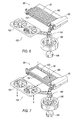
- FIG. 6 illustrates a schematic diagram depicting the document retention and anti-skew device in a second embodiment, with the document processor bed empty;
- FIG. 7 illustrates a schematic diagram depicting the document retention and anti-skew device in the second embodiment, with a document positioned on the document processor bed;
- FIG. 8 is a block diagram illustrating a moving MICR/image subsystem including a document retention and anti-skew device.
- FIG. 9 illustrates a waveform for magnetic ink characters/symbols 3, 5, 7, Amount when the document containing the characters/symbols is inserted face up for front image capture in the hand-operated document reader/imager, and the magnetic ink characters/symbols are passed over from right to left.
- the E-13B character set contains ten characters and four symbols as defined in the ANS X9.100-20-2006 (formerly published as X9.27) “Print and Test Specifications for Magnetic Ink Printing (MICR)” as published by Accredited Standards Committee X9, Inc., Annapolis, Md., United States. When used on a document for automated machine reading, the characters and symbols in the set must be printed using magnetic ink.
- ANS X9.100-20-2006 defines the dimensions of each character/symbol and the expected nominal waveform peak position and relative amplitude of waveform peaks.
- FIG. 1 shows the waveform for the magnetic ink character one, from the E-13B MICR character set, as read from a responsive magnetic signal gap read head when the magnetized character is passed by the magnetic read head.
- the waveform is indicated at 50 .
- the x-axis represents the position of the read head, and the y-axis represents the signal level.
- MICR reading and recognition generally involves determining peak position information for a waveform generated by a single gap magnetic read head that passes over the magnetic ink characters on a document.
- This peak information typically includes information regarding the amount of time between the peaks of each character.
- Knowledge of the velocity of the document (and thus, the velocity of the characters which are printed on the document) allows this time information to be converted into distance information, which can be compared to the MICR character peak profiles as contained in ANS X9.100-20-2006.
- a read head is generally indicated at 60 , and includes a gap 62 .
- the read head utilizes sensing coil 64 .
- Core 66 forms a path for the magnetic flux changes experienced when the reader passes over magnetic ink.
- alternative readers may be used, and any suitable technique may be utilized for assuring that flux variation from the magnetic ink characters is sensed.
- FIGS. 3-5 illustrate a hand-operated document reader/imager 80 .
- document reader/imager 80 includes a moving MICR/image subsystem 82 .
- Subsystem 82 includes a contact image sensor 84 , and a MICR read head 86 .
- Contact image sensor 84 captures an image of the document 100 when subsystem 82 is moved across the document 100 .
- Contact image sensor 84 captures the front image of the document 100 when the document 100 is placed face-up on the base 92 of the reader/imager 80 and the MICR/image subsystem 82 is moved from right to left over document 100 as indicated by arrow 102 .
- MICR read head 86 is for reading the magnetic ink character data 104 on document 100 .
- the MICR code line is read according to a traditional MICR algorithm as MICR read head 86 passes from right to left over the magnetic ink character data 104 on document 100 .
- the operator provides the force needed to move the MICR/image subsystem 82 over the document 100 .
- Moving MICR/image subsystem 82 rides along a linear guide shaft 152 and holds the contact image sensor 84 and the magnetic read head 86 .
- the magnetic read head 86 reads the MICR code line 104 at the bottom of the document 100 , and the contact image sensor 84 scans the document 100 .
- a document 100 is positioned on the base 92 of the hand-operated reader/imager 80 (as depicted in FIG. 5 ).
- the operator slides the MICR subsystem 82 across the length of the check or document being scanned.
- a document retention device 150 includes manually-powered anti-skew methodology.
- the base 92 of the document reader/imager 80 includes a high friction surface. Further, base 92 includes a perforated bed 160 .
- a hand-cocked, spring-driven vacuum solenoid or diaphragm assembly includes vacuum solenoid 162 , actuating rod 164 , and actuation driving spring 166 .
- the check or document 100 is positioned on the perforated bed 160 as shown in FIG. 5 .
- Manual actuator lever 168 is pulled to compress spring 166 and latched at latch mechanism 170 .
- lever 168 is shown in the latched position.
- the moving MICR/image module 82 trips a photo sensor 172 . Any other suitable sensor may be used in the alternative.
- the sensor 172 has multiple functions, such as turning on the MICR read head 86 and image sensor module 84 .
- tripping the sensor 172 releases the spring-driven vacuum solenoid 162 which is packaged under the bed ( FIGS. 4 and 5 schematically illustrate the mechanism to facilitate understanding of the concept) and had been manually cocked prior to the start of the scan.
- the vacuum solenoid 162 creates a vacuum which is ducted by vacuum line 174 to a chamber under the perforated bed 160 .
- this retention methodology in a hand-operated system eliminates skew and securely retains the checks or documents.
- the vacuum solenoid 162 is preferably sized to maintain this vacuum over the maximum time required to scan the largest allowed document.
- the uncovered perforations in the high friction bed 160 provide the only path to bleed off the vacuum. Accordingly, the rate at which the vacuum bleeds off is regulated by the size of the check or document 100 and the percentage of perforations exposed. In this way, the bleed off rate of the vacuum is self-regulating in that a large check with a longer scan time will expose fewer perforations and hold the vacuum longer than a small check with a shorter scan time.
- the bed or base 92 of the device 80 includes the high friction surface/perforated bed 160 , and the device 80 further includes a manually spun-up inertia wheel 180 that drives fans 182 , mounted under the perforated bed 160 (shown out of position to better illustrate the concept).
- tripping the sensor 172 or other suitable engagement switch at the start of the scanning operation engages a clutch 184 on the inertia wheel 180 which is packaged under the bed and had been manually spun-up prior to the start of the scan.
- the inertia wheel 180 and associated components are preferably sized to maintain this vacuum at least over the maximum time required to scan the largest allowed document.
- the inertia wheel 180 may also be arranged to drive the scan module 82 over the check or document 100 being processed as shown, but this is not required and the operator may provide the force necessary to drive the scan module.
- the inertia wheel 180 is spun up.
- a generic spin-up mechanism is depicted at 186 .
- the operator presses the release to engage clutch 184 to drive the movable MICR/image subsystem 82 .
- the energy stored in the inertia wheel 180 drives the moving MICR/image subsystem 82 over the face of the document 100 at a controlled speed.
- the inertia wheel 180 and drive ratio should be sized so that the energy stored in the spinning inertia wheel 180 will be much larger than the required energy to accelerate the mass of the scan subsystem 82 and overcome the system drag and the load of the return spring (not shown), so that the speed of the scan will be nearly constant. With a properly sized inertia wheel 180 , it should be possible to scan multiple documents before the wheel speed drops low enough to require re-acceleration.
- the uncovered perforations in the high friction bed 160 provide the only path for the fans 182 to pull air. Accordingly, the amount of vacuum and the total air flow is regulated by the size of the check or document 100 and the percentage of perforations exposed. In this way, the vacuum is self-regulating in that a large check with a longer scan time will expose fewer perforations and hold higher vacuum longer than a small check with a shorter scan time.
- a signal indicative of the speed of the MICR subsystem 82 is provided to the MICR reading and recognition logic during the scan operation.
- the speed of the module In order for the image sensor and magnetic read head to properly read the check or document, the speed of the module must be known over the entire length of the item being scanned. The speed of the scan can be measured by any one of a number of speed measuring devices. The greater the variation of speed, the more sophisticated, and therefore more expensive, the electronics must be, as well as the greater the chance of error.
- a hand-operated document reader/imager requires a method of determining the position, and thus the speed, of the MICR and image sensors due to the variable speed nature of the manual operation.
- Existing solutions use optical encoders to provide this position feedback.
- Optical encoders are typically attached directly to the shaft of a wheel that moves along the document being scanned, or are connected to this shaft through a series of gears.
- a suitable encoder 230 measures the speed of the MICR subsystem.
- An output signal from encoder 230 is provided to the MICR reading and recognition logic during the scan operation.
- FIG. 8 illustrates the moving MICR/image subsystem 82 in block diagram form, including the contact image sensor 84 , MICR read head 86 , and document retention and anti-skew device 150 which may take the form of the above-described vacuum solenoid mechanism or inertial wheel mechanism.
- the document 100 is placed on the base of the reader/imager for front image capture.
- Moving MICR/image subsystem 82 is moved across the document 100 as indicated by arrow 102 .
- Block 120 represents the MICR reading and recognition logic.
- Logic 120 includes a traditional MICR algorithm as understood by one of ordinary skill in the art.
- the waveform obtained from the read head 86 is compared against known MICR character peak profiles 122 . If the recognition is successful, the MICR reading and recognition logic 120 determines the recognized MICR characters 124 .
- the traditional MICR algorithm is applied during the front image capture by contact image sensor 84 of a face-up document. The captured image is indicated at 126 .
- Logic 120 must be capable of determining the speed of the MICR and image sensors due to the variable nature of the manual operation.
- retention and anti-skew device 150 retains the document 100 against the device bed.
- Speed feedback to the MICR reading and recognition logic 120 may be provided in any suitable way.
- FIG. 9 illustrates a waveform 200 for magnetic ink characters/symbols 3, 5, 7, Amount when the document containing the characters/symbols is inserted face up for front image capture in the hand-operated document reader/imager, and the magnetic ink characters/symbols are passed over from right to left.
- the x-axis represents the position of the read head
- the y-axis represents the signal level.
- the MICR reading and recognition logic is able to produce the waveform depicted at 200 based on the signal from the MICR read head and the speed feedback signal. In this way, the MICR reading and recognition logic can consider the MICR read head speed during reading and recognition.
- MICR read head speed is required because speed variations affect the amount of time between the peaks of each character (as well as the amplitudes of the peaks due to the variation in the rate of change of the magnetic flux resulting from the variation in the read head speed).
- the time information is able to be converted into distance information, which can be compared to the MICR character peak profiles as contained in ANS X9.100-20-2006.
- the MICR read head signal is sampled at a resolution of 1,000 samples per inch.
- the sampling rate of the MICR subsystem is varied based on the sensed speed. For example, in order to achieve 1,000 samples per inch, a speed feedback mechanism commands the MICR sampling subsystem to sample every 0.001 inches. In the embodiments of the invention illustrated in FIGS. 3-8 , this speed feedback is provided by the encoder 230 . Similarly, speed feedback could be used to command the imaging subsystem to achieve a desired samples/inch resolution.
Abstract
Description
Claims (15)
Priority Applications (1)
| Application Number | Priority Date | Filing Date | Title |
|---|---|---|---|
| US11/949,860 US8104683B1 (en) | 2007-12-04 | 2007-12-04 | Hand-operated document reader/imager with document retention device including manually-powered anti-skew methodology |
Applications Claiming Priority (1)
| Application Number | Priority Date | Filing Date | Title |
|---|---|---|---|
| US11/949,860 US8104683B1 (en) | 2007-12-04 | 2007-12-04 | Hand-operated document reader/imager with document retention device including manually-powered anti-skew methodology |
Publications (1)
| Publication Number | Publication Date |
|---|---|
| US8104683B1 true US8104683B1 (en) | 2012-01-31 |
Family
ID=45508071
Family Applications (1)
| Application Number | Title | Priority Date | Filing Date |
|---|---|---|---|
| US11/949,860 Expired - Fee Related US8104683B1 (en) | 2007-12-04 | 2007-12-04 | Hand-operated document reader/imager with document retention device including manually-powered anti-skew methodology |
Country Status (1)
| Country | Link |
|---|---|
| US (1) | US8104683B1 (en) |
Citations (3)
| Publication number | Priority date | Publication date | Assignee | Title |
|---|---|---|---|---|
| US5256863A (en) * | 1991-11-05 | 1993-10-26 | Comark Technologies, Inc. | In-store universal control system |
| US5519511A (en) * | 1993-05-31 | 1996-05-21 | Sony Corporation | Scanner device and guide therefor |
| US20080130070A1 (en) * | 2006-11-09 | 2008-06-05 | Pertech Resources, Inc. | Scanner/imager |
-
2007
- 2007-12-04 US US11/949,860 patent/US8104683B1/en not_active Expired - Fee Related
Patent Citations (3)
| Publication number | Priority date | Publication date | Assignee | Title |
|---|---|---|---|---|
| US5256863A (en) * | 1991-11-05 | 1993-10-26 | Comark Technologies, Inc. | In-store universal control system |
| US5519511A (en) * | 1993-05-31 | 1996-05-21 | Sony Corporation | Scanner device and guide therefor |
| US20080130070A1 (en) * | 2006-11-09 | 2008-06-05 | Pertech Resources, Inc. | Scanner/imager |
Similar Documents
| Publication | Publication Date | Title |
|---|---|---|
| KR100392971B1 (en) | Complex processing unit and its control method | |
| US6290129B2 (en) | Apparatus and method for printing on media and detecting information magnetically recorded on the media | |
| EP3216201B1 (en) | System and method for sorting scanned documents to selected output trays | |
| US8457383B2 (en) | Recording device and control method for a recording device | |
| US7837109B2 (en) | Processing method and apparatus for recording media having printed magnetic ink characters | |
| EP1041806A2 (en) | Printer and control method for the same | |
| US20120019841A1 (en) | Document scanner | |
| TW201215088A (en) | Method for document scanning | |
| US8382102B2 (en) | Transportation alignment device, control method for a transportation alignment device, and recording device | |
| US8104683B1 (en) | Hand-operated document reader/imager with document retention device including manually-powered anti-skew methodology | |
| US8749801B2 (en) | Determining document characteristics prior to scanning | |
| US8028911B1 (en) | Semi-automatic spring/cylinder mechanism in a hand-operated document reader/imager | |
| US8070064B1 (en) | Hand-operated document reader/imager with speed limiting device providing document retention | |
| US9036222B2 (en) | Document scanner | |
| US8083143B1 (en) | Semi-automatic inertial wheel device in a hand-operated document reader/imager | |
| EP0441964A1 (en) | Printing device of securities | |
| US8196830B1 (en) | Hand-operated document reader/imager with speed limiting device including a viscous damper to insure uniform scan rate | |
| US20130020173A1 (en) | Media processing device, check processing device, and method of controlling a media processing device | |
| JP4553847B2 (en) | Medium transport device | |
| US8002189B2 (en) | Media processing device, media processing system, and control method for a media processing system | |
| US8141779B1 (en) | Sensor and markers for speed feedback in a hand-operated document reader/imager | |
| US7900907B2 (en) | Media processing device | |
| CA2206956C (en) | Information detection apparatus and information detection method for recording media | |
| JP2023111459A (en) | Information reader | |
| US20100014744A1 (en) | Data reading apparatus, method of controlling the same, and printer |
Legal Events
| Date | Code | Title | Description |
|---|---|---|---|
| AS | Assignment |
Owner name: UNISYS CORPORATION, PENNSYLVANIA Free format text: ASSIGNMENT OF ASSIGNORS INTEREST;ASSIGNORS:HUTSON, SAMMY C;GUDENBURR, JOHN;MOORE, MICHAEL J.;SIGNING DATES FROM 20080107 TO 20080108;REEL/FRAME:020448/0692 |
|
| AS | Assignment |
Owner name: CITIBANK, N.A., NEW YORK Free format text: SUPPLEMENT TO SECURITY AGREEMENT;ASSIGNOR:UNISYS CORPORATION;REEL/FRAME:020612/0305 Effective date: 20080229 |
|
| AS | Assignment |
Owner name: UNISYS HOLDING CORPORATION, DELAWARE Free format text: RELEASE BY SECURED PARTY;ASSIGNOR:CITIBANK, N.A.;REEL/FRAME:023312/0044 Effective date: 20090601 Owner name: UNISYS CORPORATION, PENNSYLVANIA Free format text: RELEASE BY SECURED PARTY;ASSIGNOR:CITIBANK, N.A.;REEL/FRAME:023312/0044 Effective date: 20090601 |
|
| AS | Assignment |
Owner name: UNISYS CORPORATION, PENNSYLVANIA Free format text: RELEASE BY SECURED PARTY;ASSIGNOR:CITIBANK, N.A.;REEL/FRAME:023263/0631 Effective date: 20090601 Owner name: UNISYS HOLDING CORPORATION, DELAWARE Free format text: RELEASE BY SECURED PARTY;ASSIGNOR:CITIBANK, N.A.;REEL/FRAME:023263/0631 Effective date: 20090601 |
|
| AS | Assignment |
Owner name: UNISYS CORPORATION, PENNSYLVANIA Free format text: JUNIOR SECURITY RELEASE;ASSIGNOR:DEUTSCHE BANK TRUST COMPANY AMERICAS;REEL/FRAME:023882/0613 Effective date: 20100201 Owner name: UNISYS CORPORATION, PENNSYLVANIA Free format text: PRIORITY SECURITY RELEASE;ASSIGNOR:DEUTSCHE BANK TRUST COMPANY AMERICAS;REEL/FRAME:023905/0218 Effective date: 20100201 |
|
| AS | Assignment |
Owner name: BURROUGHS PAYMENT SYSTEMS, INC., MICHIGAN Free format text: ASSIGNMENT OF ASSIGNORS INTEREST;ASSIGNOR:UNISYS CORPORATION;REEL/FRAME:024006/0219 Effective date: 20100201 |
|
| AS | Assignment |
Owner name: PNC BANK, NATIONAL ASSOCIATION, AS AGENT, PENNSYLV Free format text: SECURITY AGREEMENT;ASSIGNOR:BURROUGHS PAYMENT SYSTEMS, INC.;REEL/FRAME:025591/0665 Effective date: 20101223 |
|
| AS | Assignment |
Owner name: BURROUGHS, INC., MICHIGAN Free format text: CHANGE OF NAME;ASSIGNOR:BURROUGHS PAYMENT SYSTEMS, INC.;REEL/FRAME:029340/0769 Effective date: 20120627 |
|
| FEPP | Fee payment procedure |
Free format text: PAT HOLDER NO LONGER CLAIMS SMALL ENTITY STATUS, ENTITY STATUS SET TO UNDISCOUNTED (ORIGINAL EVENT CODE: STOL); ENTITY STATUS OF PATENT OWNER: LARGE ENTITY |
|
| AS | Assignment |
Owner name: CERBERUS BUSINESS FINANCE, LLC, AS COLLATERAL AGEN Free format text: SECURITY INTEREST;ASSIGNOR:BURROUGHS, INC.;REEL/FRAME:034880/0894 Effective date: 20150130 |
|
| REMI | Maintenance fee reminder mailed | ||
| LAPS | Lapse for failure to pay maintenance fees | ||
| STCH | Information on status: patent discontinuation |
Free format text: PATENT EXPIRED DUE TO NONPAYMENT OF MAINTENANCE FEES UNDER 37 CFR 1.362 |
|
| FP | Lapsed due to failure to pay maintenance fee |
Effective date: 20160131 |
|
| AS | Assignment |
Owner name: BURROUGHS, INC. (FORMERLY KNOWN AS BURROUGHS PAYME Free format text: RELEASE OF SECURITY INTEREST IN PATENTS;ASSIGNOR:PNC BANK, NATIONAL ASSOCIATION;REEL/FRAME:039897/0823 Effective date: 20150130 |
|
| AS | Assignment |
Owner name: BURROUGHS, INC., MICHIGAN Free format text: PARTIAL RELEASE OF SECURITY INTEREST IN PATENTS;ASSIGNOR:CERBERUS BUSINESS FINANCE, LLC AS COLLATERAL AGENT;REEL/FRAME:040070/0649 Effective date: 20160919 |
|
| AS | Assignment |
Owner name: DIGITAL CHECK CORPORATION, ILLINOIS Free format text: ASSIGNMENT OF ASSIGNORS INTEREST;ASSIGNOR:BURROUGHS, INC.;REEL/FRAME:040247/0502 Effective date: 20160916 |
|
| AS | Assignment |
Owner name: BMO HARRIS BANK N.A., ILLINOIS Free format text: SECURITY INTEREST;ASSIGNOR:DIGITAL CHECK CORP.;REEL/FRAME:040631/0208 Effective date: 20160919 |
|
| AS | Assignment |
Owner name: BURROUGHS, INC., MICHIGAN Free format text: RELEASE OF SECURITY INTEREST IN PATENTS;ASSIGNOR:CERBERUS BUSINESS FINANCE, LLC;REEL/FRAME:044961/0842 Effective date: 20171222 |