US8112096B2 - System and method for locating an unknown base station - Google Patents
System and method for locating an unknown base station Download PDFInfo
- Publication number
- US8112096B2 US8112096B2 US12/250,910 US25091008A US8112096B2 US 8112096 B2 US8112096 B2 US 8112096B2 US 25091008 A US25091008 A US 25091008A US 8112096 B2 US8112096 B2 US 8112096B2
- Authority
- US
- United States
- Prior art keywords
- network
- offset
- node
- value
- lmu
- Prior art date
- Legal status (The legal status is an assumption and is not a legal conclusion. Google has not performed a legal analysis and makes no representation as to the accuracy of the status listed.)
- Expired - Fee Related, expires
Links
- 238000000034 method Methods 0.000 title claims abstract description 89
- 238000005259 measurement Methods 0.000 claims abstract description 91
- 238000004891 communication Methods 0.000 claims abstract description 40
- 230000001360 synchronised effect Effects 0.000 claims description 14
- 230000005540 biological transmission Effects 0.000 claims description 8
- 238000005516 engineering process Methods 0.000 claims description 6
- 230000007774 longterm Effects 0.000 claims description 6
- 230000001413 cellular effect Effects 0.000 claims description 5
- 238000010295 mobile communication Methods 0.000 claims description 5
- LCTONWCANYUPML-UHFFFAOYSA-N Pyruvic acid Chemical compound CC(=O)C(O)=O LCTONWCANYUPML-UHFFFAOYSA-N 0.000 description 85
- 208000000143 urethritis Diseases 0.000 description 17
- 238000004364 calculation method Methods 0.000 description 3
- 239000003550 marker Substances 0.000 description 3
- 230000008901 benefit Effects 0.000 description 2
- 238000005070 sampling Methods 0.000 description 2
- 238000013459 approach Methods 0.000 description 1
- 239000000969 carrier Substances 0.000 description 1
- 230000001934 delay Effects 0.000 description 1
- 230000001419 dependent effect Effects 0.000 description 1
- 230000009365 direct transmission Effects 0.000 description 1
- 238000001914 filtration Methods 0.000 description 1
- 238000012986 modification Methods 0.000 description 1
- 230000004048 modification Effects 0.000 description 1
- 230000000737 periodic effect Effects 0.000 description 1
- 238000011084 recovery Methods 0.000 description 1
- 230000002441 reversible effect Effects 0.000 description 1
- 101150011184 toa1 gene Proteins 0.000 description 1
- 101150108701 toa2 gene Proteins 0.000 description 1
- 238000012549 training Methods 0.000 description 1
Images


Classifications
-
- H—ELECTRICITY
- H04—ELECTRIC COMMUNICATION TECHNIQUE
- H04W—WIRELESS COMMUNICATION NETWORKS
- H04W24/00—Supervisory, monitoring or testing arrangements
- H04W24/10—Scheduling measurement reports ; Arrangements for measurement reports
-
- G—PHYSICS
- G01—MEASURING; TESTING
- G01R—MEASURING ELECTRIC VARIABLES; MEASURING MAGNETIC VARIABLES
- G01R31/00—Arrangements for testing electric properties; Arrangements for locating electric faults; Arrangements for electrical testing characterised by what is being tested not provided for elsewhere
- G01R31/08—Locating faults in cables, transmission lines, or networks
-
- G—PHYSICS
- G01—MEASURING; TESTING
- G01S—RADIO DIRECTION-FINDING; RADIO NAVIGATION; DETERMINING DISTANCE OR VELOCITY BY USE OF RADIO WAVES; LOCATING OR PRESENCE-DETECTING BY USE OF THE REFLECTION OR RERADIATION OF RADIO WAVES; ANALOGOUS ARRANGEMENTS USING OTHER WAVES
- G01S19/00—Satellite radio beacon positioning systems; Determining position, velocity or attitude using signals transmitted by such systems
- G01S19/01—Satellite radio beacon positioning systems transmitting time-stamped messages, e.g. GPS [Global Positioning System], GLONASS [Global Orbiting Navigation Satellite System] or GALILEO
- G01S19/13—Receivers
- G01S19/24—Acquisition or tracking or demodulation of signals transmitted by the system
- G01S19/25—Acquisition or tracking or demodulation of signals transmitted by the system involving aiding data received from a cooperating element, e.g. assisted GPS
- G01S19/252—Employing an initial estimate of location in generating assistance data
-
- G—PHYSICS
- G01—MEASURING; TESTING
- G01S—RADIO DIRECTION-FINDING; RADIO NAVIGATION; DETERMINING DISTANCE OR VELOCITY BY USE OF RADIO WAVES; LOCATING OR PRESENCE-DETECTING BY USE OF THE REFLECTION OR RERADIATION OF RADIO WAVES; ANALOGOUS ARRANGEMENTS USING OTHER WAVES
- G01S19/00—Satellite radio beacon positioning systems; Determining position, velocity or attitude using signals transmitted by such systems
- G01S19/38—Determining a navigation solution using signals transmitted by a satellite radio beacon positioning system
- G01S19/39—Determining a navigation solution using signals transmitted by a satellite radio beacon positioning system the satellite radio beacon positioning system transmitting time-stamped messages, e.g. GPS [Global Positioning System], GLONASS [Global Orbiting Navigation Satellite System] or GALILEO
- G01S19/42—Determining position
- G01S19/45—Determining position by combining measurements of signals from the satellite radio beacon positioning system with a supplementary measurement
- G01S19/46—Determining position by combining measurements of signals from the satellite radio beacon positioning system with a supplementary measurement the supplementary measurement being of a radio-wave signal type
-
- G—PHYSICS
- G01—MEASURING; TESTING
- G01S—RADIO DIRECTION-FINDING; RADIO NAVIGATION; DETERMINING DISTANCE OR VELOCITY BY USE OF RADIO WAVES; LOCATING OR PRESENCE-DETECTING BY USE OF THE REFLECTION OR RERADIATION OF RADIO WAVES; ANALOGOUS ARRANGEMENTS USING OTHER WAVES
- G01S5/00—Position-fixing by co-ordinating two or more direction or position line determinations; Position-fixing by co-ordinating two or more distance determinations
- G01S5/02—Position-fixing by co-ordinating two or more direction or position line determinations; Position-fixing by co-ordinating two or more distance determinations using radio waves
- G01S5/0205—Details
-
- G—PHYSICS
- G01—MEASURING; TESTING
- G01S—RADIO DIRECTION-FINDING; RADIO NAVIGATION; DETERMINING DISTANCE OR VELOCITY BY USE OF RADIO WAVES; LOCATING OR PRESENCE-DETECTING BY USE OF THE REFLECTION OR RERADIATION OF RADIO WAVES; ANALOGOUS ARRANGEMENTS USING OTHER WAVES
- G01S5/00—Position-fixing by co-ordinating two or more direction or position line determinations; Position-fixing by co-ordinating two or more distance determinations
- G01S5/02—Position-fixing by co-ordinating two or more direction or position line determinations; Position-fixing by co-ordinating two or more distance determinations using radio waves
- G01S5/0257—Hybrid positioning
- G01S5/0268—Hybrid positioning by deriving positions from different combinations of signals or of estimated positions in a single positioning system
-
- G—PHYSICS
- G01—MEASURING; TESTING
- G01S—RADIO DIRECTION-FINDING; RADIO NAVIGATION; DETERMINING DISTANCE OR VELOCITY BY USE OF RADIO WAVES; LOCATING OR PRESENCE-DETECTING BY USE OF THE REFLECTION OR RERADIATION OF RADIO WAVES; ANALOGOUS ARRANGEMENTS USING OTHER WAVES
- G01S5/00—Position-fixing by co-ordinating two or more direction or position line determinations; Position-fixing by co-ordinating two or more distance determinations
- G01S5/02—Position-fixing by co-ordinating two or more direction or position line determinations; Position-fixing by co-ordinating two or more distance determinations using radio waves
- G01S5/10—Position of receiver fixed by co-ordinating a plurality of position lines defined by path-difference measurements, e.g. omega or decca systems
-
- H—ELECTRICITY
- H04—ELECTRIC COMMUNICATION TECHNIQUE
- H04W—WIRELESS COMMUNICATION NETWORKS
- H04W64/00—Locating users or terminals or network equipment for network management purposes, e.g. mobility management
-
- H—ELECTRICITY
- H04—ELECTRIC COMMUNICATION TECHNIQUE
- H04W—WIRELESS COMMUNICATION NETWORKS
- H04W84/00—Network topologies
- H04W84/02—Hierarchically pre-organised networks, e.g. paging networks, cellular networks, WLAN [Wireless Local Area Network] or WLL [Wireless Local Loop]
- H04W84/04—Large scale networks; Deep hierarchical networks
Definitions
- any electromagnetic wave emitting object may be located by utilizing sensors that receive the waves combined with an a geolocation process such as triangulation, multilateration, AOA, etc.
- a geolocation process such as triangulation, multilateration, AOA, etc.
- LMUs location measurement units
- multilateration i.e., TDOA positioning
- at least four LMUs are generally required resulting in three independent hyperbolas.
- the intersection point of these three hyperbolas may be the estimated location of the unknown base station or Node B. In some cases, however, these hyperbolas may not intersect exactly at one point, and a more accurate location may be determined based on the LMU geometry, received signal quality, etc.
- Embodiments of the present subject matter therefore provide a novel method and system to derive OTDOA information from the existing mobile devices and base stations utilizing messages typically used for normal operation of the mobile device.
- measurement report messages e.g., network measurement reports
- UMTS mobile devices report these messages to a base station for proper operation.
- These messages contain the Connection Frame Number (“CFN”)—System Frame Number (“SFN”) information between serving and neighbor nodes, such as, but not limited to, base stations, base station sectors, cells, etc.
- CFN Connection Frame Number
- SFN System Frame Number
- Embodiments of the present subject matter may also derive a neighboring node's SFN-SFN OTD from this information.
- OTDOAs of the neighboring node downlink may be determined.
- Embodiments of the present subject matter may therefore make it possible to determine downlink OTDOA values for mobile devices that do not support the OTDOA feature through the exploitation of network measurement reports that are generally not intended for location determination.
- an embodiment of the present subject matter provides a method for estimating a location of an unknown Node B in a wireless communications system having a plurality of known nodes.
- the method may comprise determining an OTDOA hyperbola based on signals received from the unknown Node B and one of the known nodes.
- the OTDOA hyperbola may be determined using information received from a user equipment network measurement report, the user equipment being at any known location.
- Another embodiment of the present subject matter may provide a method for estimating a location of an unknown Node B in a wireless communication system having a plurality of other nodes and a plurality of LMUs.
- the method may comprise determining first and second values based on a network timing characteristic for ones of the nodes.
- An OTDOA hyperbola may be calculated based on the first and second values, and a location of the unknown Node B determined as a function of the OTDOA hyperbola.
- a further embodiment of the present subject matter may provide another method for estimating a location of an unknown Node B in a wireless communication system having a plurality of other nodes and a plurality of LMUs.
- the method may comprise determining a first value based on a network measurement report characteristic, a second value based on a first network timing characteristic, a third value based on a second network timing characteristic, and a fourth value based on a third network timing characteristic.
- An OTDOA hyperbola may be calculated based on at least one of the first, second, third, or fourth values, and a location of the unknown Node B estimated as a function of the OTDOA hyperbola.
- An additional embodiment of the present subject may provide a further method for estimating a location of an unknown Node B in a wireless communication system having a plurality of other nodes and a plurality of LMUs.
- the method may comprise determining a first value based on a first network measurement report characteristic, a second value based on a second network measurement report characteristic, a third value based on a first network timing characteristic, and a fourth value based on a second network timing characteristic.
- An OTDOA hyperbola may be calculated based on at least one of the first, second, third, or fourth values, and a location of the unknown Node B estimated as a function of the OTDOA hyperbola.
- Another embodiment of the present subject matter may provide an additional method for estimating a location of an unknown Node B in a wireless communication system having a plurality of other nodes and a plurality of LMUs.
- the method may comprise determining a first value based on a first network measurement report characteristic, a second value based on a second network measurement report characteristic, a third value based on a third network measurement report characteristic, and a fourth value based on a network timing characteristic.
- An OTDOA hyperbola may be calculated based on at least one of the first, second, third, or fourth values, a location of the unknown Node B estimated as a function of the OTDOA hyperbola.
- One embodiment of the present subject matter may provide a system for estimating a location of an unknown Node B in a wireless communication system having a plurality of other nodes and a plurality of LMUs.
- the system may comprise circuitry for determining a first value based on a network timing characteristic for one of the nodes and circuitry for determining a second value based on a network measurement report characteristic.
- the system may also include circuitry for calculating an OTDOA hyperbola based on the first and second values and circuitry for estimating a location of said unknown Node B as a function of said OTDOA hyperbola.
- Another embodiment of the present subject matter provides a method for estimating a location of an unknown Node B in a wireless communication system having a plurality of other nodes and a plurality of LMUs.
- the method may include determining a first value based on a first network timing characteristic of the unknown Node B at a first LMU and determining a second value based on a second network timing characteristic of the unknown Node B at a second LMU.
- One or more OTDOA hyperbolas may be calculated based on at least the first and second values.
- a third value based may be determined on a third network timing characteristic of a known Node B at one of said first or second LMUs.
- a first timing offset value between the known and unknown Node Bs may be determined as a function of any one or combination of the first, second and third values, and a second timing offset value between the known and unknown Node Bs determined using a UE network measurement report.
- a propagation delay from the known Node B to the LMU or UE may be determined as a function of the timing offset values, and one or more OTDOA hyperbolas calculated based on ones of the first timing offset value, second timing offset value, third value, and propagation delay.
- a location of the unknown Node B may then be estimated as a function of said OTDOA hyperbolas.
- FIG. 1 is an illustration of a wireless communications network according to an embodiment of the present subject matter.
- FIGS. 2-5 are pictorial representations of a system and method for locating an unknown base station according to embodiments of the present subject matter.
- FIG. 6 is an algorithm according to an embodiment of the present subject matter.
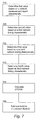
- FIG. 7 is an algorithm according to another embodiment of the present subject matter.
- FIG. 8 is an algorithm according to yet another embodiment of the present subject matter.
- FIG. 9 is an algorithm according to one embodiment of the present subject matter.
- FIG. 10 is an illustration of a communications system according to an embodiment of the present subject matter.
- FIG. 11 is another algorithm according to one embodiment of the present subject matter.
- Embodiments of the present subject matter may provide several methods to derive timing information.
- the positions of the same mobile device, other mobile devices, or base stations may be determined completely, or partly, from calculated hyperbolas, from observed time differences (“OTDs”), or from other values.
- OTDs observed time differences
- Timing relationships may tend to drift over time as a function of oscillator characteristics utilized in respective base stations. This drift must be accounted for when utilizing these methods, either through periodic updating of the estimated base station time relationships (base station timing offsets or “BSTOs”) or through known means to track and predict timing relationships via prediction methods based on past measurement timing trends.
- Exemplary means of prediction are well-known in the industry and are a manageable problem to those skilled in the art, and will thus not be the subject of further discussion herein.
- OTDs generally define a set of handset based measurements known in the 3GPP standard such as System Frame Number “SFN-SFN” Type 1 and/or Type 2. These measurements are generally the observed time difference of two nodes such as base station cells or sectors and differ primarily in the timing resolution of the measurements. For example, with Type 1, a mobile device measures the timing difference between the Primary Common Control Physical Channels (“P-CCPCH”) of cell 1 and cell 2 . Type 1 is generally available on a CELL_FACH connection. While a soft handover cannot be performed while on a CELL_FACH connection, the network may request the mobile device to measure the timing difference between cell 1 and cell 2 .
- P-CCPCH Primary Common Control Physical Channels
- a Measurement Control Message may be sent to the mobile device on the Forward Access Channel (“FACH”), and the mobile device's measurement results are returned on the Reverse Access Channel (“RACH”).
- FACH Forward Access Channel
- RACH Reverse Access Channel
- the mobile device measures the timing difference between the Common Pilot Channels (“CPICH”) of cell 1 and cell 2 .
- CPICH Common Pilot Channels
- Type 2 is applicable to both CELL_DCH and CELL_FACH connections. With either connection type, if there is power in cell 2 , the mobile may measure the timing difference between the two cells.
- the mobile device may measure OTDs while in soft handover with cells 1 and 2 .
- SFN-Connection Frame Number Another set of handset based measurements known in the 3GPP standard is SFN-Connection Frame Number (“CFN”). These measurements refer to the observed time difference between the connection to a current serving base station cell and some set of handset-measurable, neighboring cells or sectors.
- NSUs network synchronization units
- One NSU based solution may provide a GPS trained NSU at one or more base stations within a communications network.
- the NSU may have knowledge of the co-located site's scrambling code and may also continuously estimate the timing of the downlink frame marker.
- chip offset (0-38399) information of the rounded frame and chip offset term in the network measurement report absolute SFN timing within 256 frames may not be required. Therefore, knowledge of frame timing markers (having a period of 38400 chips (10 ms)) may generally be adequate for this purpose.
- SFN timing information may be maintained in a timing bank to provide accurate timing relationships of neighbor SFNs at appropriate measurement reporting times.
- embodiments of the present subject matter employed in OFDMA based systems utilize sampling time as the time unit.
- the timing offset would be a sample offset rather than a chip offset. Therefore, chip offset, timing offset, sample offset may be utilized interchangeably throughout the present disclosure and the use of one term without the others should not in any way limit the scope of the claims appended herewith.
- embodiments of the present subject matter are not directly dependent of SFN, these certain embodiments may be employed in systems operating under the Long Term Evolution (“LTE”) standard, by way of a non-limiting example, and frame offset or frame marker offset would be equally applicable thereto. Therefore, SFN, frame offset, and frame marker offset may be utilized interchangeably throughout the present disclosure and the use of one term without the others should not in any way limit the scope of the claims appended herewith.
- LTE Long Term Evolution
- Another embodiment of the present subject matter may employ a sparse deployment of NSUs to reduce hardware deployment cost and track SFN timing.
- a GPS trained NSU preferably within line of sight of one or more base stations and positioned at a known location, may measure the timing of several scrambling codes associated with one or more neighboring cells or nodes. With knowledge of the precise location of several base stations and the NSU, SFN timing at the neighboring sites may then be determined. Further, as some of the downlink signals may be detected at multiple NSUs, multipath may also be resolved by selecting the earliest SFN timing of a base station.
- Multiples of 256 chips timing offset between different sectors of a base station may assist in identifying the scrambling code group of a base station.
- the modulo 256 chip timing offset characteristics may assist in determining the SFN timing for co-located sectors if the timing of only one sector is known. This latter technique may, of course, be utilized for sparse NSU deployments.
- the sparse NSU deployment approach may be useful in locating unknown base stations. For example, where the location of one or more base stations is not readily available from the carrier, the downlink of a particular base station may be detected at multiple NSU sites, and the base station may then be located with the downlink TDOA information.
- FIG. 1 is an illustration of an exemplary wireless communications network according to an embodiment of the present subject matter.
- a wireless communications network 100 or system is shown.
- the network may be a Global System for Mobile Communication (“GSM”) network, a Time Division Multiple Access (“TDMA”) network, Code Division Multiple Access (“CDMA”) network, a UMTS network, an Orthogonal Frequency Division Multiple Access (“OFMDA”) network, a Worldwide Interoperability for Microwave Access (“WiMax”) network, a WiFi network, networks utilizing Evolution-Data Optimized (“EDVO”), CDMA2000 network, 1 times Radio Transmission Technology (“1 ⁇ RTT”), Long Term Evolution (“LTE”) standards or another equivalent network.
- GSM Global System for Mobile Communication
- TDMA Time Division Multiple Access
- CDMA Code Division Multiple Access
- UMTS Code Division Multiple Access
- OFD Orthogonal Frequency Division Multiple Access
- WiMax Worldwide Interoperability for Microwave Access
- WiFi Wireless Fidelity
- EDVO Evolution-Data Optimized
- CDMA2000
- LMU Location measurement units
- NSUs 115 may be dispersed throughout the system or subsystem reception area. NSUs 115 may be integrated with one or more base stations 102 - 106 or may be independent of a base station 102 - 106 and may be sparsely deployed through the network 100 .
- the wireless network 100 serves mobile stations, UE or devices 120 , 122 within reception range of at least one of the base stations 102 - 106 .
- Mobile stations 120 , 122 may include cellular telephones, text messaging devices, computers, portable computers, vehicle locating devices, vehicle security devices, communication devices, wireless transceivers or other devices with a wireless communications interface.
- Base station transceivers 102 - 106 may be operably connected to a central entity or central network unit 130 .
- the central entity 130 may be a base station controller (“BSC”) in a base station subsystem (“BSS”), a Radio Network Controller (“RNC”) in a Radio Access Network (“RAN”), or, for GSM, General Packet Radio Service (“GPRS”) or UMTS system, a serving mobile location center (“SMLC”) or an equivalent.
- BSC base station controller
- BSS base station subsystem
- RNC Radio Network Controller
- RAN Radio Access Network
- GSM Global System for Mobile Communications
- GPRS General Packet Radio Service
- UMTS serving mobile location center
- connection from each base station to a BSC, SMLC or other central network entity may employ a direct transmission link, e.g., a wired connection, microwave link, Ethernet connection, and the like, or may be employed by one or more intermediate entities, e.g., an intermediate BSC in the case of a connection from a BTS to an SMLC for GSM.
- a direct transmission link e.g., a wired connection, microwave link, Ethernet connection, and the like
- intermediate entities e.g., an intermediate BSC in the case of a connection from a BTS to an SMLC for GSM.
- Each mobile station 120 , 122 may periodically measure the transmission timing difference between pairs of base stations 102 - 106 and/or receive network measurement reports from the network 100 .
- a mobile station 120 may measure the difference in transmission timing for communication from its serving base station 102 and from one or more neighboring base stations, e.g., 106 and/or 103 .
- Either the mobile station or the base station may remove differences attributed primarily to propagation delays between the mobile station and base station antennas to produce a timing difference, determining timing relationships, and/or determine other values or characteristics.
- frame offset and chip offset of the neighboring nodes or cells may be generally reported in a measurement report such as a network measurement report.
- the chip offset may generally be required for OTDOA computation.
- a shift of 38400 chips may be added or subtracted to align the frame markers as necessary.
- embodiments of the present subject matter employed in OFDMA based systems may utilize sampling time as an appropriate time unit.
- FIG. 2 is a pictorial representation of a system and method for locating an unknown base station according to an embodiment of the present subject matter.
- the location of an unknown Node B 10 such as a cell or base station (“BTS”), may be determined from four LMUs, 21 - 24 .
- Each of the four LMUs 21 - 24 may receive signals from the unknown BTS 10 .
- the time of arrival for each LMU may be represented as TOA1, TOA2, TOA3 and TOA4. From these TOAs, respective observed time difference of arrivals may be determined.
- the observed TDOAs between three pairs of LMUs 21 - 22 , 22 - 23 , 23 - 24 are represented as TDOA12, TDOA23 and TDOA34, respectively.
- the intersection point of the three hyperbolas is an estimated location of the unknown BTS 10 .
- four LMUs have been illustrated, such an example should not limit the scope of the claims appended herewith as embodiments of the present subject matter may utilize more than four LMUs to calculate redundant hyperbolas to make the system over-determined and provide a location estimate minimizing any estimation error.
- three LMUs may be utilized to determine a location of the unknown BTS 10 if there is a prior knowledge regarding the location of the unknown BTS 10 .
- three LMUs would result in two hyperbolas. These two hyperbolas may intersect at two points wherein one of the intersection points can be eliminated using the prior knowledge.
- FIG. 3 is a pictorial representation of a system and method for locating an unknown base station according to an embodiment of the present subject matter.
- the location of an unknown Node B or BTS 10 may be determined from three LMUs, 21 - 23 , one mobile station 31 (“UE”), and one known BTS 11 .
- the UE 31 in this exemplary network may measure the timing offset between the unknown and known BTSs 10 , 11 and report the offset to the network in a measurement report. It should be noted that this embodiment of the present subject matter is not limited by the cellular technology employed in the network so long as the timing offset is reported by the UE.
- an exemplary system may be a GSM network, a TDMA network, CDMA network, CDMA2000 network, a UMTS network, an OFDMA network, a WiMax network, a WiFi network, networks utilizing EDVO, 1 ⁇ RTT, LTE standards or another equivalent network.
- the timing offset may be reported as SFN-SFN (type 1 or 2) or CFN-SFN.
- the timing offset may also be reported in terms of frames, time slots, chips, samples, or symbols and may be converted to an appropriate unit such as seconds, etc.
- Equation (1) Equation (2)
- Tp_k_lmu1 and Tp_k_ue may be determined assuming line of site propagation between the LMU 21 and BTS 11 and the UE 31 and BTS 11 .
- TO_lmu1 is also known since the value is measured by the LMU 21 .
- TO_ue is known as the UE 31 reports this value in a measurement report.
- Tp_u_lmu1 ⁇ Tp_u_ue may be determined: (Tp_u_lmu1 ⁇ Tp_u_ue) may generally be identified as TDOA — 1ue and represents the observed time difference of arrival between the LMU 21 and UE 31 for a transmission from the unknown BTS 10 . This value may also represent a hyperbola drawn between the LMU 21 and UE 31 .
- the timing offset between the unknown and known BTSs 10 , 11 (TO_lmu1) may or may not be measured at the same time as the timing offset measurement determined by the UE 31 .
- an interpolation or another exemplary algorithm or process such as Kalman filtering may be employed to align the measurement time of the LMU 21 with the measurement time of the UE 31 to account for the timing drifts the BTSs may have.
- the LMUs 21 , 22 , 23 measure the TOA_u_lmu1, TOA_u_lmu2, and TOA_u_lmu3, respectively, as the time of arrival for the unknown BTS 10 . From these TOAs, observed time difference of arrivals TDOA — 12 and TDOA — 23 may be determined along with the corresponding hyperbolas. The intersection point of the three hyperbolas, TDOA — 1ue, TDOA — 12 and TDOA — 23, may be the estimated location of the unknown BTS 10 . In another embodiment, additional hyperbolas may be provided to the location solution by moving the UE 31 to different locations or by utilizing measurement reports from other UEs at different locations. Furthermore, multiple LMU measurements and multiple UE measurements may be utilized and/or combined to achieve a more accurate location.
- FIG. 4 is a pictorial representation of a system and method for locating an unknown base station according to an embodiment of the present subject matter.
- the location of an unknown Node B or BTS 10 may be determined from two LMUs 21 , 22 and two UEs 31 , 32 .
- Equation (13) may thus define the hyperbola TDOA1 shown in FIG. 4 .
- Equation (16) may generally define the hyperbola TDOA2 illustrated in FIG. 4 .
- the observed time difference of arrival of the unknown BTS 10 between the LMUs 21 , 22 (TOA_u_lmu1 ⁇ TOA_u_lmu2) may define the hyperbola TDOA3 illustrated in FIG. 4 .
- the intersection point of the three hyperbolas, TDOA1, TDOA2, TDOA3, may represent an estimated location of the unknown BTS 10 .
- FIG. 5 is a pictorial representation of a system and method for locating an unknown base station according to an embodiment of the present subject matter.
- the location of an unknown Node B or BTS 10 may be determined from one LMU 21 and three UEs 31 , 32 , 33 .
- these UEs may be a single UE moved to different locations in the network to provide measurement reports from the different locations at different times.
- these UEs may be any number of separate UEs and the example depicted in the figure should not limit the scope of the claims appended herewith.
- the timing offsets between the known BTS 11 and the unknown BTS 10 as measured by the UEs 31 , 32 , 33 may be represented by the following relationships, respectively:
- TOA_u_ue1 represents the time of arrival of a signal from the unknown BTS 10 at the UE 31
- TOA_u_ue2 represents the time of arrival of a signal from the unknown BTS 10 at the UE 32
- TOA_u_ue3 represents the time of arrival of a signal from the unknown BTS 10 at the UE 33 .
- Tx_k represents the transmit time of the known BTS 11
- Tp_k_ue1 represents the propagation delay for a signal from the known BTS 11 to the UE 31
- Tp_k_ue2 represents the propagation delay for a signal from the known BTS 11 to the UE 32
- Tp_k_ue3 represents the propagation delay for a signal from the known BTS 11 to the UE 33 .
- Tx_u represents the transmit time of the unknown BTS 10
- Tp_u_ue1 represents the propagation delay for a signal from the unknown BTS 10 to the UE 31
- Tp_u_ue2 represents the propagation delay for a signal from the unknown BTS 10 to the UE 32
- Tp_u_ue3 represents the propagation delay for a signal from the unknown BTS 10 to the UE 33 .
- Equations (21), (22), and (23) may each generally define respective hyperbolas, TDOA1, TDOA2, TDOA3, between the LMU 21 and the UEs 31 , 32 , 33 illustrated in FIG. 5 .
- the intersection point of the three hyperbolas TDOA1, TDOA2, TDOA3 represents an estimated location of the unknown BTS 10 .
- FIG. 6 is an algorithm according to an embodiment of the present subject matter.
- a method for estimating a location of an unknown Node B in a wireless communication system having a plurality of other nodes and a plurality of LMUs is provided.
- Exemplary nodes may be, but are not limited to, base stations, base station sectors, and combinations thereof.
- An exemplary communication system may be, but is not limited, to a UMTS network, WiMax network, GSM network, OFDMA network, WiFi network, and CDMA network. Further, the system may operate under a standard such as IS-95, EDVO, CDMA2000, LTE and 1 ⁇ RTT.
- the nodes may or may not be synchronized.
- the nodes may be synchronized as a function of information received from a satellite signal or may be synchronized as a function of information transmitted from a component of the system such as an NSU.
- first and second values based on a network timing characteristic for any one or several of the nodes may be determined.
- the network timing characteristic may be a frame offset such as an SFN and the like.
- An OTDOA hyperbola based on the first and second values may be calculated at step 620 .
- a location of the unknown Node B may then be estimated as a function of the OTDOA hyperbola.
- a third value such as a round trip time (“RTT”) value, a cell identification value, a signal strength value, etc., may be determined to assist in estimating the location of the unknown Node B.
- RTT round trip time
- FIG. 7 is an algorithm according to another embodiment of the present subject matter.
- a method for estimating a location of an unknown Node B in a wireless communication system having a plurality of other nodes and a plurality of LMUs is provided.
- a first value based on a network measurement report characteristic may be determined.
- the network measurement report characteristic may be a time offset between a first node and the unknown Node B.
- the first node may be a serving or neighboring BTS or node.
- a second value based on a first network timing characteristic may be determined, at step 730 , a third value based on a second network timing characteristic may be determined, and at step 740 a fourth value based on a third network timing characteristic may be determined.
- Any one or combination of the first, second and third network timing characteristics may be an exemplary frame or time offset.
- the first network timing characteristic may be a time offset between a first node and the unknown Node B measured by an LMU.
- the second network timing characteristic may be a time offset between the first node and the unknown Node B measured by another LMU.
- the third network timing characteristic may be a time offset between the first node and the unknown Node B measured by a third LMU.
- Exemplary nodes may be base stations, base station sectors, and combinations thereof, and the nodes may or may not be synchronized.
- An OTDOA hyperbola may then be calculated based on at least one of the first, second, third, or fourth values at step 750 , and at step 760 , a location of the unknown Node B may be estimated as a function of the OTDOA hyperbola.
- the calculation of the OTDOA hyperbola may include calculating a first OTDOA hyperbola based on the first and second values, calculating a second OTDOA hyperbola based on the second and third values, and calculating a third OTDOA hyperbola based on the third and fourth values.
- the estimated location of the unknown Node B may be a function of an RTT value, a cell identification value, a signal strength value, etc.
- FIG. 8 is an algorithm according to a further embodiment of the present subject matter.
- a method for estimating a location of an unknown Node B in a wireless communication system having a plurality of other nodes and a plurality of LMUs is provided.
- a first value based on a first network measurement report characteristic may be determined
- a second value based on a second network measurement report characteristic may be determined.
- the first network measurement report characteristic may be a time offset between a serving or neighboring node and the unknown Node B
- the second network measurement report characteristic may be another time offset between a neighboring or serving node and the unknown Node B.
- Exemplary wireless devices may be, but are not limited to, a cellular device, text messaging device, computer, portable computer, vehicle locating device, vehicle security device, communication device, and wireless transceiver.
- exemplary time offsets may be a chip offset, frame offset, symbol offset and sample offset.
- a third value based on a first network timing characteristic may be determined, and at step 840 a fourth value based on a second network timing characteristic may be determined.
- the first and second network timing characteristics may be an exemplary frame or time offset.
- the first network timing characteristic may be a time offset between a serving or neighboring node and the unknown Node B measured by an LMU.
- the second network timing characteristic may be a time offset between a neighboring or serving node and the unknown Node B measured by another LMU.
- Exemplary nodes may be base stations, base station sectors, and combinations thereof and the nodes may or may not be synchronized.
- An OTDOA hyperbola may then be calculated based on at least one of the first, second, third, or fourth values at step 850 , and at step 860 , a location of the unknown Node B estimated as a function of the OTDOA hyperbola.
- the calculation of the OTDOA hyperbola may include calculating a first OTDOA hyperbola based on the first and second values, calculating a second OTDOA hyperbola based on the second and third values, and calculating a third OTDOA hyperbola based on the third and fourth values.
- the estimated location of the unknown Node B may be a function of an RTT value, a cell identification value, a signal strength value, etc.
- FIG. 9 is an algorithm according to an additional embodiment of the present subject matter.
- a method for estimating a location of an unknown Node B in a wireless communication system having a plurality of other nodes and a plurality of LMUs is provided.
- a first value based on a first network measurement report characteristic may be determined
- a second value based on a second network measurement report characteristic may be determined
- a third value based on a third network measurement report characteristic may be determined.
- the first network measurement report characteristic may be a first time offset between a serving or neighboring node and the unknown Node B
- the second network measurement report characteristic may be a second time offset between the serving or neighboring node and the unknown Node B
- the third network measurement report characteristic may be a third time offset between the serving or neighboring node and the unknown Node B.
- An exemplary wireless device may be a cellular device, text messaging device, computer, portable computer, vehicle locating device, vehicle security device, communication device, and wireless transceiver.
- any one or combination of the first, second or third time offsets may be a chip offset, frame offset, symbol offset and/or sample offset.
- a fourth value based on a network timing characteristic may be determined.
- the network timing characteristic may be an exemplary frame or time offset.
- the network timing characteristic may be a time offset between a serving or neighboring node and the unknown Node B measured by an LMU.
- Exemplary nodes may be base stations, base station sectors, and combinations thereof and the nodes may or may not be synchronized.
- An OTDOA hyperbola based on at least one of the first, second, third, or fourth values may then be calculated at step 950 , and at step 960 a location of the unknown Node B estimated as a function of the OTDOA hyperbola.
- the calculation of the OTDOA hyperbola may include calculating a first OTDOA hyperbola based on the first and second values, calculating a second OTDOA hyperbola based on the second and third values, and calculating a third OTDOA hyperbola based on the third and fourth values.
- the estimated location of the unknown Node B may be a function of an RTT value, a cell identification value, a signal strength value, etc.
- FIG. 10 is an illustration of a communications system according to an embodiment of the present subject matter.
- a system 1000 is illustrated for estimating a location of an unknown Node B in a wireless communication system having a plurality of other nodes and a plurality of LMUs.
- the system 1000 may be a UMTS network, WiMax network, GSM network, OFDMA network, WiFi network, or CDMA network and may operate under a standard such as, but not limited to, IS-95, EDVO, LTE, CDMA2000, and 1 ⁇ RTT.
- the system 1000 may include circuitry 1010 for determining a first value based on a network timing characteristic for one of the nodes, and circuitry 1020 for determining a second value based on a network measurement report characteristic.
- Exemplary nodes may be, but are not limited to, base stations, base station sectors, and combinations thereof. Further, the nodes may or may not be synchronized. For example, the nodes may be synchronized as a function of information received from a satellite signal or may be synchronized as a function of information transmitted from a component of the system 1000 such as an NSU.
- An exemplary network timing characteristic may be a frame offset such as a SFN or the like.
- An exemplary network measurement report characteristic may be, but is not limited to, a time offset value such as a chip offset value, sample offset value, etc.
- Circuitry 1030 for calculating an OTDOA hyperbola based on the first and second values may also be included in the system 1000 .
- the system 1000 may further comprise circuitry 1040 for estimating a location of the unknown Node B as a function of the OTDOA hyperbola.
- FIG. 11 is another algorithm according to an embodiment of the present subject matter.
- an exemplary method 1100 is illustrated for estimating a location of an unknown Node B in a wireless communication system having a plurality of other nodes and a plurality of LMUs.
- the method 1100 may include at step 1110 , determining a first value based on a first network timing characteristic of the unknown Node B at a first LMU and at step 1120 , determining a second value based on a second network timing characteristic of the unknown Node B at a second LMU.
- Exemplary first and second values may be downlink timing values of the unknown Node B.
- One or more OTDOA hyperbolas may then be calculated based on at least the first and second values at step 1130 .
- a third value may be determined based on a third network timing characteristic of a known Node B at one of the first or second LMUs.
- a first timing offset value between the known and unknown Node Bs may be determined from any combination of the first, second and third values, and at step 1160 , a second timing offset value may be determined between the known and unknown Node Bs using a network measurement report from a UE at any known location.
- the propagation delay from the known Node B to the LMU and/or UE may then be determined as a function of the timing offset values at step 1170 , and one or more OTDOA hyperbolas calculated based on any combination of the first timing offset value, second timing offset value, third value, and propagation delay at step 1180 .
- a location of the unknown Node B may then be estimated as a function of the OTDOA hyperbolas at step 1190 .
- the LMUs may measure the time of arrival of known and unknown base stations
- the UEs may measure the timing offset between the known and unknown base stations.
- Hyperbolas between LMUs and between LMUs and UEs may be computed utilizing the LMU and UE measurements. Additional hyperbolas generated by UE measurements may also provide location estimations in situations where there are not enough LMU-LMU hyperbolas due to sparse deployment of LMUs or due to low BTS hearability at the LMUs. Even in embodiments having sufficient LMU-LMU hyperbolas for location estimations, inclusion of additional LMU-UE hyperbolas may increase the accuracy of the location estimation.
- such synchronization may be accomplished by several alternative methods including, but not limited to, training a node's oscillator by a GPS sourced signal, tracking the signal of a neighboring node, etc.
- the timing offset between nodes may be measured and appropriately subtracted from the respective computation described above.
- an NSU or timing measurement unit (“TMU”) may be utilized to directly estimate the timing offset.
- another embodiment may deploy a timing bank that utilizes measurement reports from a GPS enabled mobile device to track the base station drift.
- hyperbolas between two or more nodes such as neighboring and/or serving nodes or cells using the knowledge of base station SFN timing and the CFN-SFN measurements at a UE.
- location information provided by the hyperbolas as a component of a hybrid solution method that uses other location techniques such as Cell-ID, E-CID, RTT, A-GPS, UTDOA, and/or RSSI based techniques.
- any combination of one or more LMUs, one or more UEs, one or more known base stations, and one or more unknown base stations may be utilized. Further, measurement reports from one UE at different locations at different times may also be employed in embodiments of the present subject matter. Additionally, other well-known triangulation methods may be employed to estimate the most likely location of an unknown BTS and the discussion of time difference of arrivals herein should not limit the scope of the claims appended herewith.
Abstract
Description
TO — ue=TOA — k — ue−TOA — u — ue (1)
where TOA_k_ue represents the time of arrival for the known
TOA — k — ue=Tx — k+Tp — k — ue (2)
TOA — u — ue=Tx — u+Tp — u — ue (3)
where Tx_k represents the transmit time of the known
TO — ue=(Tx — k+Tp — k — ue)−(Tx — u+Tp — u — ue) (4)
TO — lmu1=TOA — k — lmu1−TOA — u — lmu1 (5)
where TOA_k_lmu1 represents the time of arrival for the known
TOA — k — lmu1=Tx — k+Tp — k — lmu1 (6)
TOA — u — lmu1=Tx — u+Tp — u — lmu1 (7)
where Tp_k_lmu1 represents the propagation delay from the known
TO — lmu1=(Tx — k+Tp — k — lmu1)−(Tx — u+Tp — u — lmu1) (8)
TO — lmu1−TO — ue=(Tp — k — lmu1−Tp — k — ue)−(Tp — u — lmu1−Tp — u — ue) (9)
(Tp — u — lmu1−Tp — u — ue)=(Tp — lmu1−Tp — k — ue)−(TO — lmu1−TO — ue) (10)
TO — ue1=TOA — k1— ue1−TOA — u — ue1=(Tx — k1+Tp — k1— ue1)−(Tx — u+Tp — u — ue1) (11)
where TOA_k1_ue1 represents the time of arrival of a signal from the known
TO — lmu1=TOA — k1— lmu1−TOA — u — lmu1=(Tx — k1+Tp — k1— lmu1)−(Tx — u+Tp — u — lmu1) (12)
where TOA_k1_lmu1 represents the time of arrival of a signal from the known
Tp — u — lmu1−Tp — u — ue1=(Tp — k1— lmu1−Tp — k1— ue1)−(TO — lmu1−TO — ue1) (13)
TO — ue2=TOA — k2— ue2−TOA — u — ue2=(Tx — k2+Tp — k2— ue2)−(Tx — u+Tp — u — ue2) (14)
where TOA_k2_ue2 represents the time of arrival of a signal from the known
TO — lmu2=TOA — k2— lmu2−TOA — u — lmu2=(Tx — k2+Tp — k2— lmu2)−(Tx — u+Tp — u — lmu2) (15)
where TOA_k2_lmu2 represents the time of arrival of a signal from the known
Tp — u — lmu2−Tp — u — ue2=(Tp — k2— lmu2−Tp — k2— ue2)−(TO — lmu2−TO — ue2) (16)
TO — ue1=TOA — k — ue1−TOA — u — ue1=(Tx — k+Tp — k — ue1)−(Tx — u+Tp — u — ue1) (17)
TO — ue2=TOA — k — ue2−TOA — u — ue2=(Tx — k+Tp — k — ue2)−(Tx — u+Tp — u — ue2) (18)
TO — ue3=TOA — k — ue3−TOA — u — ue3=(Tx — k+Tp — k — ue3)−(Tx — u+Tp — u — ue3) (19)
where TOA_k_ue1 represents the time of arrival of a signal from the known
TO — lmu=TOA — k — lmu−TOA — u — lmu=(Tx — k — lmu)−(Tx — u+Tp — u — mu) (20)
where TOA_k_lmu represents the time of arrival of a signal from the known
(Tp — u — lmu−Tp — u — ue1)=(Tp — k — lmu−Tp — k — ue1)−(TO — lmu−TO — ue1) (21)
(Tp — u — lmu−Tp — u — ue2)=(Tp — k — lmu−Tp — k — ue2)−(TO — lmu−TO — ue2) (22)
(Tp — u — lmu−Tp — u — ue3)=(Tp — k — lmu−Tp — k — ue3)−(TO — lmu−TO — ue3) (23)
Claims (45)
Priority Applications (1)
| Application Number | Priority Date | Filing Date | Title |
|---|---|---|---|
| US12/250,910 US8112096B2 (en) | 2007-11-15 | 2008-10-14 | System and method for locating an unknown base station |
Applications Claiming Priority (2)
| Application Number | Priority Date | Filing Date | Title |
|---|---|---|---|
| US99641207P | 2007-11-15 | 2007-11-15 | |
| US12/250,910 US8112096B2 (en) | 2007-11-15 | 2008-10-14 | System and method for locating an unknown base station |
Publications (2)
| Publication Number | Publication Date |
|---|---|
| US20090131075A1 US20090131075A1 (en) | 2009-05-21 |
| US8112096B2 true US8112096B2 (en) | 2012-02-07 |
Family
ID=40642515
Family Applications (2)
| Application Number | Title | Priority Date | Filing Date |
|---|---|---|---|
| US12/104,250 Expired - Fee Related US8447319B2 (en) | 2007-11-15 | 2008-04-16 | System and method for locating UMTS user equipment using measurement reports |
| US12/250,910 Expired - Fee Related US8112096B2 (en) | 2007-11-15 | 2008-10-14 | System and method for locating an unknown base station |
Family Applications Before (1)
| Application Number | Title | Priority Date | Filing Date |
|---|---|---|---|
| US12/104,250 Expired - Fee Related US8447319B2 (en) | 2007-11-15 | 2008-04-16 | System and method for locating UMTS user equipment using measurement reports |
Country Status (6)
| Country | Link |
|---|---|
| US (2) | US8447319B2 (en) |
| AU (1) | AU2008322574A1 (en) |
| CA (1) | CA2705759A1 (en) |
| ES (1) | ES2377088A1 (en) |
| GB (1) | GB2466904B (en) |
| TW (1) | TW200931054A (en) |
Cited By (8)
| Publication number | Priority date | Publication date | Assignee | Title |
|---|---|---|---|---|
| US20110136501A1 (en) * | 2009-12-08 | 2011-06-09 | Britt Jr Joe Freeman | Location service for wireless devices |
| US20130324163A1 (en) * | 2012-06-01 | 2013-12-05 | Qualcomm Incorporated | Obtaining timing of LTE wireless base stations using aggregated OTDOA assistance data |
| US8954089B2 (en) | 2012-06-01 | 2015-02-10 | Qualcomm Incorporated | Positioning LTE wireless base stations using aggregated OTDOA assistance data |
| US9078229B1 (en) | 2013-01-08 | 2015-07-07 | Polaris Wireless, Inc. | Base station location derived from wireless terminal information |
| US9088943B1 (en) | 2013-01-08 | 2015-07-21 | Polaris Wireless, Inc. | Base station timing derived from wireless terminal information |
| US9144055B2 (en) | 2013-10-15 | 2015-09-22 | Qualcomm Incorporated | Method and apparatus for asynchrosous positioning of wireless base stations |
| US9749810B1 (en) | 2016-02-23 | 2017-08-29 | At&T Mobility Ii Llc | User equipment assisted indoor small cell location determination |
| US11632271B1 (en) | 2022-02-24 | 2023-04-18 | T-Mobile Usa, Inc. | Location-based channel estimation in wireless communication systems |
Families Citing this family (70)
| Publication number | Priority date | Publication date | Assignee | Title |
|---|---|---|---|---|
| US8892112B2 (en) | 2011-07-21 | 2014-11-18 | At&T Mobility Ii Llc | Selection of a radio access bearer resource based on radio access bearer resource historical information |
| US7949503B2 (en) * | 2008-07-07 | 2011-05-24 | King Fahd University Of Petroleum And Minerals | Facilities optimization method |
| US8326319B2 (en) | 2009-01-23 | 2012-12-04 | At&T Mobility Ii Llc | Compensation of propagation delays of wireless signals |
| US8125943B2 (en) * | 2009-02-19 | 2012-02-28 | Mediatek Inc. | Method for positioning user equipment accessing multiple mobile networks |
| CN106102166B (en) * | 2009-05-29 | 2019-12-24 | 瑞典爱立信有限公司 | Signaling measurements for positioning in a wireless network |
| CN102461289B (en) * | 2009-05-29 | 2016-08-03 | 瑞典爱立信有限公司 | Signal measurement in the wireless network for positioning |
| US8965395B2 (en) * | 2009-06-05 | 2015-02-24 | Qualcomm Incorporated | Positioning of user equipment in a wireless communication network |
| US9002354B2 (en) * | 2009-06-12 | 2015-04-07 | Google Technology Holdings, LLC | Interference control, SINR optimization and signaling enhancements to improve the performance of OTDOA measurements |
| US8463292B2 (en) * | 2009-06-29 | 2013-06-11 | Telefonaktiebolaget Lm Ericsson (Publ) | TDOA—based reconstruction of base station location data |
| US20100331012A1 (en) * | 2009-06-29 | 2010-12-30 | Yang Zhang | TDOA-Based Reconstruction of Base Station Location Data |
| CN101990219A (en) * | 2009-07-30 | 2011-03-23 | 中兴通讯股份有限公司 | Processing method of measurement report and user equipment |
| EP2462461A1 (en) * | 2009-08-05 | 2012-06-13 | Andrew LLC | System and method for hybrid location in an lte network |
| CN101990299A (en) | 2009-08-07 | 2011-03-23 | 中兴通讯股份有限公司 | Method and device for positioning terminal by using base station |
| US20120163222A1 (en) * | 2009-08-14 | 2012-06-28 | Tariqul Islam | System and method for locating a wireless device in a wimax network using uplink signals |
| TWI397714B (en) * | 2009-10-29 | 2013-06-01 | Univ Nat Taiwan | Localization method and system thereof |
| US9084216B2 (en) | 2009-11-20 | 2015-07-14 | Qualcomm Incorporated | Method and apparatus for enhancement of cell ID-based position determination in TD-SCDMA multimode terminals |
| WO2011100859A1 (en) * | 2010-02-19 | 2011-08-25 | Telefonaktiebolaget L M Ericsson (Publ) | Improvements on otdoa and agnss positioning and timing information obtaining and updating |
| US9008684B2 (en) | 2010-02-25 | 2015-04-14 | At&T Mobility Ii Llc | Sharing timed fingerprint location information |
| US9196157B2 (en) | 2010-02-25 | 2015-11-24 | AT&T Mobolity II LLC | Transportation analytics employing timed fingerprint location information |
| US9053513B2 (en) | 2010-02-25 | 2015-06-09 | At&T Mobility Ii Llc | Fraud analysis for a location aware transaction |
| US8224349B2 (en) | 2010-02-25 | 2012-07-17 | At&T Mobility Ii Llc | Timed fingerprint locating in wireless networks |
| PT2569973T (en) | 2010-05-10 | 2018-05-28 | Ericsson Telefon Ab L M | Methods and apparatus for supporting inter-frequency measurements |
| US9119036B2 (en) | 2010-05-10 | 2015-08-25 | Telefonaktiebolaget L M Ericsson (Publ) | Enhanced measurement gap configuration support for positioning |
| EP2569974B1 (en) | 2010-05-10 | 2014-09-24 | Telefonaktiebolaget LM Ericsson (publ) | Method and apparatus for measurement configuration support |
| MX2013001732A (en) * | 2010-08-16 | 2013-03-22 | Ericsson Telefon Ab L M | Positioning node, user equipment and methods therein. |
| US8447328B2 (en) | 2010-08-27 | 2013-05-21 | At&T Mobility Ii Llc | Location estimation of a mobile device in a UMTS network |
| GB2484916B (en) * | 2010-10-25 | 2013-02-27 | Percello Ltd | Passive locating of umts handsets |
| US8675554B2 (en) * | 2010-11-08 | 2014-03-18 | Intel Corporation | Wireless communication device and method for performing neighbor cell analysis during continuous packet connectivity mode |
| US9009629B2 (en) | 2010-12-01 | 2015-04-14 | At&T Mobility Ii Llc | Motion-based user interface feature subsets |
| US8315647B2 (en) * | 2010-12-28 | 2012-11-20 | Trueposition, Inc. | Time and power based wireless location detection system |
| US8655377B2 (en) | 2010-12-28 | 2014-02-18 | Trueposition, Inc. | Time and power based wireless location and method of selecting location estimate solution |
| US8655348B2 (en) * | 2011-02-18 | 2014-02-18 | Pctel, Inc. | System and method for acquiring network data |
| EP2708081A1 (en) * | 2011-05-11 | 2014-03-19 | Telefonaktiebolaget LM Ericsson (PUBL) | A radio network node, a node and methods therein for enabling enhanced cell id timing measurement for positioning of a user equipment |
| US9462497B2 (en) | 2011-07-01 | 2016-10-04 | At&T Mobility Ii Llc | Subscriber data analysis and graphical rendering |
| US9519043B2 (en) | 2011-07-21 | 2016-12-13 | At&T Mobility Ii Llc | Estimating network based locating error in wireless networks |
| US8897802B2 (en) | 2011-07-21 | 2014-11-25 | At&T Mobility Ii Llc | Selection of a radio access technology resource based on radio access technology resource historical information |
| US8761799B2 (en) * | 2011-07-21 | 2014-06-24 | At&T Mobility Ii Llc | Location analytics employing timed fingerprint location information |
| WO2013023159A1 (en) * | 2011-08-10 | 2013-02-14 | Spidercloud Wireless, Inc. | Method and apparatus for topology management for handovers in heterogeneous networks |
| US8923134B2 (en) | 2011-08-29 | 2014-12-30 | At&T Mobility Ii Llc | Prioritizing network failure tickets using mobile location data |
| US8762048B2 (en) | 2011-10-28 | 2014-06-24 | At&T Mobility Ii Llc | Automatic travel time and routing determinations in a wireless network |
| US8909247B2 (en) | 2011-11-08 | 2014-12-09 | At&T Mobility Ii Llc | Location based sharing of a network access credential |
| US9026133B2 (en) | 2011-11-28 | 2015-05-05 | At&T Mobility Ii Llc | Handset agent calibration for timing based locating systems |
| US8970432B2 (en) | 2011-11-28 | 2015-03-03 | At&T Mobility Ii Llc | Femtocell calibration for timing based locating systems |
| US8925104B2 (en) | 2012-04-13 | 2014-12-30 | At&T Mobility Ii Llc | Event driven permissive sharing of information |
| US20130285856A1 (en) * | 2012-04-30 | 2013-10-31 | Qualcomm Incorporated | Position and Uncertainty Determination Using Staggered Reception of Position Reference Signals |
| US9432964B2 (en) | 2012-05-21 | 2016-08-30 | Qualcomm Incorporated | Method and apparatus for determining locations of access points |
| US8761781B2 (en) * | 2012-05-30 | 2014-06-24 | At&T Mobility Ii Llc | Facilitation of determination of antenna location |
| US8929827B2 (en) | 2012-06-04 | 2015-01-06 | At&T Mobility Ii Llc | Adaptive calibration of measurements for a wireless radio network |
| US9094929B2 (en) | 2012-06-12 | 2015-07-28 | At&T Mobility Ii Llc | Event tagging for mobile networks |
| US9326263B2 (en) | 2012-06-13 | 2016-04-26 | At&T Mobility Ii Llc | Site location determination using crowd sourced propagation delay and location data |
| US9046592B2 (en) | 2012-06-13 | 2015-06-02 | At&T Mobility Ii Llc | Timed fingerprint locating at user equipment |
| US8938258B2 (en) | 2012-06-14 | 2015-01-20 | At&T Mobility Ii Llc | Reference based location information for a wireless network |
| US8897805B2 (en) | 2012-06-15 | 2014-11-25 | At&T Intellectual Property I, L.P. | Geographic redundancy determination for time based location information in a wireless radio network |
| US9408174B2 (en) | 2012-06-19 | 2016-08-02 | At&T Mobility Ii Llc | Facilitation of timed fingerprint mobile device locating |
| EP2865214A4 (en) * | 2012-06-20 | 2015-07-08 | Ericsson Telefon Ab L M | Method and network node for enabling position determination of a user equipment measurement |
| US8892054B2 (en) | 2012-07-17 | 2014-11-18 | At&T Mobility Ii Llc | Facilitation of delay error correction in timing-based location systems |
| US9351223B2 (en) | 2012-07-25 | 2016-05-24 | At&T Mobility Ii Llc | Assignment of hierarchical cell structures employing geolocation techniques |
| CN103906228B (en) * | 2012-12-28 | 2018-04-10 | 中国电信股份有限公司 | Base station Differential positioning method, positioner and the system of mobile terminal |
| DE102013104727A1 (en) * | 2013-05-07 | 2014-11-13 | Deutsche Telekom Ag | Method and apparatus for determining the position of a mobile communication device |
| WO2015057156A2 (en) * | 2013-10-18 | 2015-04-23 | Telefonaktiebolaget L M Ericsson (Publ) | Over-the-air synchronization for small cells in a wireless communication network |
| EP2911462B1 (en) * | 2014-01-31 | 2020-04-15 | Avago Technologies International Sales Pte. Limited | Time offset acquisition for dual connectivity |
| EP2928244B1 (en) * | 2014-03-31 | 2016-11-30 | Alcatel Lucent | A user terminal, a base station, and a method of determining received signal power and location of a user terminal |
| US9599698B2 (en) | 2014-12-02 | 2017-03-21 | Intel Corporation | Enhanced positioning system using hybrid filter |
| US9351111B1 (en) | 2015-03-06 | 2016-05-24 | At&T Mobility Ii Llc | Access to mobile location related information |
| US10397739B2 (en) * | 2017-03-03 | 2019-08-27 | Here Global B.V. | Supporting the creation of a radio map |
| US10605889B2 (en) | 2017-08-23 | 2020-03-31 | Locix, Inc. | Systems and methods for precise radio frequency localization using time sweep time difference of arrival |
| US10568064B2 (en) | 2017-08-23 | 2020-02-18 | Locix, Inc. | Systems and methods for precise radio frequency localization using time difference of arrival |
| US10516972B1 (en) | 2018-06-01 | 2019-12-24 | At&T Intellectual Property I, L.P. | Employing an alternate identifier for subscription access to mobile location information |
| US11304169B2 (en) | 2018-12-19 | 2022-04-12 | Qualcomm Incorporated | Differential round trip time based positioning |
| US10966055B1 (en) | 2019-01-02 | 2021-03-30 | Locationdas Inc. | Positioning using distributed antenna system with service and location information availability monitoring and dynamic recovery |
Citations (130)
| Publication number | Priority date | Publication date | Assignee | Title |
|---|---|---|---|---|
| US3150372A (en) | 1959-06-23 | 1964-09-22 | Motorola Inc | Computing system |
| US3659085A (en) | 1970-04-30 | 1972-04-25 | Sierra Research Corp | Computer determining the location of objects in a coordinate system |
| US4728959A (en) | 1986-08-08 | 1988-03-01 | Ventana Sciences Inc. | Direction finding localization system |
| US4814751A (en) | 1987-02-27 | 1989-03-21 | Wildlife Materials, Inc. | Patient tracking system |
| US4845504A (en) | 1987-04-08 | 1989-07-04 | M/A-Com, Inc. | Mobile radio network for nationwide communications |
| US4891650A (en) | 1988-05-16 | 1990-01-02 | Trackmobile Inc. | Vehicle location system |
| US5056106A (en) | 1990-08-02 | 1991-10-08 | Wang James J | Golf course ranging and direction-finding system using spread-spectrum radiolocation techniques |
| US5218618A (en) | 1990-11-07 | 1993-06-08 | Hughes Aircraft Company | Cellular telephone service using spread spectrum transmission |
| US5245634A (en) | 1992-03-23 | 1993-09-14 | Motorola, Inc. | Base-site synchronization in a communication system |
| US5317323A (en) | 1993-03-05 | 1994-05-31 | E-Systems, Inc. | Passive high accuracy geolocation system and method |
| US5327144A (en) | 1993-05-07 | 1994-07-05 | Associated Rt, Inc. | Cellular telephone location system |
| US5365544A (en) | 1990-12-05 | 1994-11-15 | Interdigital Technology Corporation | CDMA communications and geolocation system and method |
| US5372144A (en) | 1992-12-01 | 1994-12-13 | Scimed Life Systems, Inc. | Navigability improved guidewire construction and method of using same |
| US5404376A (en) | 1993-09-09 | 1995-04-04 | Ericsson-Ge Mobile Communications Inc. | Navigation assistance for call handling in mobile telephone systems |
| US5423067A (en) | 1991-09-09 | 1995-06-06 | Nec Corporation | Digital mobile communications system and method for providing intensity/coverage reference maps using base stations and mobile stations |
| US5465289A (en) | 1993-03-05 | 1995-11-07 | E-Systems, Inc. | Cellular based traffic sensor system |
| US5506864A (en) | 1990-12-05 | 1996-04-09 | Interdigital Technology Corporation | CDMA communications and geolocation system and method |
| US5506863A (en) | 1993-08-25 | 1996-04-09 | Motorola, Inc. | Method and apparatus for operating with a hopping control channel in a communication system |
| US5508708A (en) | 1995-05-08 | 1996-04-16 | Motorola, Inc. | Method and apparatus for location finding in a CDMA system |
| US5512908A (en) | 1994-07-08 | 1996-04-30 | Lockheed Sanders, Inc. | Apparatus and method for locating cellular telephones |
| US5515419A (en) | 1992-06-01 | 1996-05-07 | Trackmobile | Tracking system and method for tracking a movable object carrying a cellular phone unit, and integrated personal protection system incorporating the tracking system |
| US5519760A (en) | 1994-06-22 | 1996-05-21 | Gte Laboratories Incorporated | Cellular network-based location system |
| US5592180A (en) | 1992-08-20 | 1997-01-07 | Nexus1994 Limited | Direction finding and mobile location system for trunked mobile radio systems |
| US5614914A (en) | 1994-09-06 | 1997-03-25 | Interdigital Technology Corporation | Wireless telephone distribution system with time and space diversity transmission for determining receiver location |
| US5675344A (en) | 1996-06-28 | 1997-10-07 | Motorola, Inc. | Method and apparatus for locating a mobile station in a spread spectrum communication system |
| US5815538A (en) | 1993-06-25 | 1998-09-29 | Omniplex, Inc. | Method and apparatus for determining location of a subscriber device in a wireless cellular communications system |
| US5825887A (en) | 1995-12-28 | 1998-10-20 | Trimble Navigation Limited | Transmitting and receiving apparatus for full code correlation operation under encryption for satellite positioning system |
| US5870029A (en) | 1996-07-08 | 1999-02-09 | Harris Corporation | Remote mobile monitoring and communication system |
| US5920278A (en) | 1997-05-28 | 1999-07-06 | Gregory D. Gibbons | Method and apparatus for identifying, locating, tracking, or communicating with remote objects |
| US5952969A (en) | 1997-08-18 | 1999-09-14 | Telefonakiebolaget L M Ericsson (Publ) | Method and system for determining the position of mobile radio terminals |
| US5960341A (en) | 1994-09-28 | 1999-09-28 | U S West, Inc. | Positioning system having an RF-measurements databank |
| US5959580A (en) | 1994-11-03 | 1999-09-28 | Ksi Inc. | Communications localization system |
| US5973643A (en) | 1997-04-11 | 1999-10-26 | Corsair Communications, Inc. | Method and apparatus for mobile emitter location |
| US5987329A (en) | 1997-07-30 | 1999-11-16 | Ericsson Inc | System and method for mobile telephone location measurement using a hybrid technique |
| US6014102A (en) | 1998-04-17 | 2000-01-11 | Motorola, Inc. | Method and apparatus for calibrating location finding equipment within a communication system |
| US6047192A (en) | 1996-05-13 | 2000-04-04 | Ksi Inc. | Robust, efficient, localization system |
| US6091362A (en) | 1999-01-08 | 2000-07-18 | Trueposition, Inc. | Bandwidth synthesis for wireless location system |
| US6097959A (en) | 1998-01-29 | 2000-08-01 | Ericsson Inc. | System and method for accurate positioning of mobile terminals |
| US6101178A (en) | 1997-07-10 | 2000-08-08 | Ksi Inc. | Pseudolite-augmented GPS for locating wireless telephones |
| US6108555A (en) | 1996-05-17 | 2000-08-22 | Ksi, Inc. | Enchanced time difference localization system |
| US6144711A (en) | 1996-08-29 | 2000-11-07 | Cisco Systems, Inc. | Spatio-temporal processing for communication |
| US6188351B1 (en) | 1998-08-13 | 2001-02-13 | Ericsson Inc. | Method for improving signal acquistion in a global positioning system receiver |
| US6191738B1 (en) | 1999-09-30 | 2001-02-20 | Motorola, Inc. | Method and apparatus for locating a remote unit within a communication system |
| US6201499B1 (en) | 1998-02-03 | 2001-03-13 | Consair Communications | Time difference of arrival measurement system |
| US6201803B1 (en) | 1995-05-02 | 2001-03-13 | British Telecommunications Public Limited Company | Cellular radio location system |
| US6212319B1 (en) | 1997-11-27 | 2001-04-03 | Dassault Electronique | Electro-optical device, notably for optical distribution |
| US6233459B1 (en) | 1997-04-10 | 2001-05-15 | The Atlantis Company, Limited, Japan | System for providing Geolocation of a mobile transceiver |
| US6246884B1 (en) | 1998-08-19 | 2001-06-12 | Sigmaone Communications Corporation | System and method for measuring and locating a mobile station signal in a wireless communication system |
| US6295455B1 (en) | 1999-06-11 | 2001-09-25 | Telefonaktiebolaget Lm Ericsson (Publ) | Methods and arrangements for locating a mobile telecommunications station |
| US6311043B1 (en) | 1998-10-27 | 2001-10-30 | Siemens Aktiengesellschaft | Method and measurement configuration for measuring the characteristics of radio channels |
| US6334059B1 (en) | 1999-01-08 | 2001-12-25 | Trueposition, Inc. | Modified transmission method for improving accuracy for e-911 calls |
| US6366241B2 (en) | 2000-06-26 | 2002-04-02 | Trueposition, Inc. | Enhanced determination of position-dependent signal characteristics of a wireless transmitter |
| US6388618B1 (en) | 1999-01-08 | 2002-05-14 | Trueposition, Inc. | Signal collection system for a wireless location system |
| US6407703B1 (en) | 2000-08-07 | 2002-06-18 | Lockheed Martin Corporation | Multi-platform geolocation method and system |
| US20020077116A1 (en) | 1999-03-18 | 2002-06-20 | Theodore Havinis | System and method for reporting the number and/or duration of positioning requests for terminal-based location calculation |
| US6463290B1 (en) | 1999-01-08 | 2002-10-08 | Trueposition, Inc. | Mobile-assisted network based techniques for improving accuracy of wireless location system |
| US6470195B1 (en) | 2000-10-31 | 2002-10-22 | Raytheon Company | Method and apparatus for modeling a smart antenna in a network planning tool |
| US6477161B1 (en) | 1998-12-21 | 2002-11-05 | Nortel Networks Limited | Downlink beamforming approach for frequency division duplex cellular systems |
| US6501955B1 (en) | 2000-06-19 | 2002-12-31 | Intel Corporation | RF signal repeater, mobile unit position determination system using the RF signal repeater, and method of communication therefor |
| US6522890B2 (en) * | 1995-12-22 | 2003-02-18 | Cambridge Positioning Systems, Ltd. | Location and tracking system |
| US6553322B1 (en) | 1999-09-29 | 2003-04-22 | Honeywell International Inc. | Apparatus and method for accurate pipeline surveying |
| US6571082B1 (en) | 1999-10-29 | 2003-05-27 | Verizon Laboratories Inc. | Wireless field test simulator |
| US20030139188A1 (en) | 2002-01-24 | 2003-07-24 | Chen Byron Hua | Geolocation using enhanced timing advance techniques |
| US6603761B1 (en) | 1999-09-17 | 2003-08-05 | Lucent Technologies Inc. | Using internet and internet protocols to bypass PSTN, GSM map, and ANSI-41 networks for wireless telephone call delivery |
| US20030148774A1 (en) | 2000-01-11 | 2003-08-07 | Siamak Naghian | Location of a mobile station in a telecommunications system |
| US20030190919A1 (en) | 2000-08-22 | 2003-10-09 | Jarko Niemenmaa | Method for positioning a mobile station |
| US6640106B2 (en) | 2001-09-20 | 2003-10-28 | Motorola, Inc. | Method and system for verifying the position of a mobile station using checkpoints |
| US20030203738A1 (en) | 2002-04-29 | 2003-10-30 | Brown Larry Michael | Method and apparatus for locating a remote unit within a communication system |
| US6646604B2 (en) | 1999-01-08 | 2003-11-11 | Trueposition, Inc. | Automatic synchronous tuning of narrowband receivers of a wireless location system for voice/traffic channel tracking |
| US20030216142A1 (en) * | 2002-05-16 | 2003-11-20 | Wigren K. Torbjorn | Position determination in wireless communication systems |
| US20040037246A1 (en) | 2002-08-21 | 2004-02-26 | Francesco Grilli | Method and system for communicating content on a broadcast services communication system |
| US20040043775A1 (en) | 2002-08-29 | 2004-03-04 | Kennedy Joseph P. | Tasking and reporting method and implementation for wireless appliance location systems |
| US20040087277A1 (en) | 2002-10-31 | 2004-05-06 | Siemens Information And Communication Mobile Llc. | Method and apparatus for improving accuracy of radio timing measurements |
| US20040132466A1 (en) | 2002-12-23 | 2004-07-08 | Kennedy Joseph P. | Method and apparatus for supporting multiple wireless carrier mobile station location requirements with a common network overlay location system |
| US20040132464A1 (en) | 2002-12-20 | 2004-07-08 | Sami Poykko | Location system |
| US6765531B2 (en) | 1999-01-08 | 2004-07-20 | Trueposition, Inc. | System and method for interference cancellation in a location calculation, for use in a wireless location system |
| US6771969B1 (en) | 2000-07-06 | 2004-08-03 | Harris Corporation | Apparatus and method for tracking and communicating with a mobile radio unit |
| US6782264B2 (en) | 1999-01-08 | 2004-08-24 | Trueposition, Inc. | Monitoring of call information in a wireless location system |
| US20040180645A1 (en) | 2003-03-11 | 2004-09-16 | Bussan Christopher F. | Location requests and measurement responses in wireless communications networks and methods |
| US20040180671A1 (en) | 2003-02-24 | 2004-09-16 | Spain David Stevenson | Location estimation of wireless terminals based on combinations of signal strength measurements and geometry-of-arrival measurements |
| US20040203921A1 (en) | 2003-03-21 | 2004-10-14 | Nicholas Bromhead | Sub-sector timing advance positions determinations |
| US20040218664A1 (en) | 2003-01-31 | 2004-11-04 | Kennedy Joseph P. | Method for angle of arrival determination on frequency hopping air interfaces |
| US20040252752A1 (en) | 2003-01-31 | 2004-12-16 | Kennedy Joseph P. | Method for calibrating an AOA location system for frequency hopping air interfaces |
| US6834234B2 (en) | 2000-11-22 | 2004-12-21 | Trimble Navigation, Limited | AINS land surveyor system with reprocessing, AINS-LSSRP |
| US6845240B2 (en) | 2000-12-11 | 2005-01-18 | Grayson Wireless | System and method for analog cellular radio geolocation |
| US6859172B2 (en) | 2003-02-17 | 2005-02-22 | Global Business Software Development Technologies, Inc. | System and method for locating a mobile phone |
| US20050058182A1 (en) | 2003-01-31 | 2005-03-17 | Kennedy Joseph P. | Method for calibrating an AOA location system for all frequencies in a frequency hopping signal |
| US6871077B2 (en) | 2001-10-09 | 2005-03-22 | Grayson Wireless | System and method for geolocating a wireless mobile unit from a single base station using repeatable ambiguous measurements |
| US6873290B2 (en) | 1999-01-08 | 2005-03-29 | Trueposition, Inc. | Multiple pass location processor |
| US6876859B2 (en) | 2001-07-18 | 2005-04-05 | Trueposition, Inc. | Method for estimating TDOA and FDOA in a wireless location system |
| US20050136945A1 (en) | 2003-12-19 | 2005-06-23 | Kennedy Joseph P. | E-OTD augmentation to U-TDOA location system |
| US6920329B2 (en) | 2001-01-16 | 2005-07-19 | Allen Telecom | Method and system for applying wireless geolocation technology |
| US6922170B2 (en) | 2002-01-24 | 2005-07-26 | Motorola, Inc. | Methods and apparatus for determining a direction of arrival in a wireless communication system |
| US20050192026A1 (en) | 2003-06-04 | 2005-09-01 | Carlson John P. | System and method for CDMA geolocation |
| US6952158B2 (en) | 2000-12-11 | 2005-10-04 | Kennedy Jr Joseph P | Pseudolite positioning system and method |
| US20060003775A1 (en) | 1999-01-08 | 2006-01-05 | Bull Jeffrey F | Advanced triggers for location-based service applications in a wireless location system |
| US20060003695A1 (en) | 2002-10-16 | 2006-01-05 | Kennedy Joseph P Jr | System and method of operation for network overlay geolocation systemwith repeaters |
| US6987979B2 (en) | 2001-12-22 | 2006-01-17 | Telefonaktiebolaget Lm Ericsson (Publ) | Locating packet-switched mobile terminals using network initiated artificial cell hops |
| US6996392B2 (en) | 2002-09-03 | 2006-02-07 | Trueposition, Inc. | E911 overlay solution for GSM, for use in a wireless location system |
| US20060116130A1 (en) | 2002-10-16 | 2006-06-01 | Andrew Corporation | Network overlay location system and method for air interface with frequency stopping |
| US7089021B2 (en) * | 2001-07-17 | 2006-08-08 | Siemens Aktiengesellschaft | Method and system for determining the position of subscriber devices of a radio communication system using additional positioning elements |
| US7127257B2 (en) | 2001-12-27 | 2006-10-24 | Qualcomm Incorporated | Use of mobile stations for determination of base station location parameters in a wireless mobile communication system |
| US20060239391A1 (en) | 2005-04-20 | 2006-10-26 | Flanagan Michael J | Evaluating base station timing in an asynchronous network |
| US20060240836A1 (en) | 2003-03-03 | 2006-10-26 | Kennedy Joseph P Jr | Independently acquiring and tracking wireless communication system signaling channel assignments on communication links |
| US7155244B2 (en) | 2003-08-14 | 2006-12-26 | Siemens Communications, Inc. | Precise common timing in a wireless network |
| US7203503B2 (en) * | 2000-03-23 | 2007-04-10 | Telefonaktiebolaget Lm Ericsson (Publ) | Method and system for locating mobile stations in a mobile communication network |
| US20070087689A1 (en) | 2003-09-26 | 2007-04-19 | Martin Alles | System and method of operation for network overlay geolocation system with repeaters using am golay hadamard signatures |
| US20070111746A1 (en) | 2005-11-16 | 2007-05-17 | Anderson Robert J | Transmit-power control for wireless mobile services |
| US20070155489A1 (en) | 2005-12-30 | 2007-07-05 | Frederic Beckley | Device and network enabled geo-fencing for area sensitive gaming enablement |
| US20070155401A1 (en) | 2005-12-30 | 2007-07-05 | Trueposition Inc. | User plane uplink time difference of arrival (u-tdoa) |
| US20070202885A1 (en) | 2003-06-24 | 2007-08-30 | Kennedy Joseph P Jr | Method For Sparse Network Deployment Accuracy Enhancements |
| US7315745B2 (en) | 2002-08-28 | 2008-01-01 | Cambridge Positioning Systems Ltd. | Radio positioning systems |
| US7346345B2 (en) * | 2002-02-15 | 2008-03-18 | Nokia Corporation | Positioning in a telecommunications system |
| US20080096566A1 (en) * | 2006-07-31 | 2008-04-24 | Qualcomm Incorporated | Determination of cell rf parameters based on measurements by user equipments |
| US7383049B2 (en) | 2001-12-27 | 2008-06-03 | Qualcomm Incorporated | Automation of maintenance and improvement of location service parameters in a data base of a wireless mobile communication system |
| US20080132244A1 (en) | 2006-12-01 | 2008-06-05 | Trueposition, Inc. | Subscriptionless location of wireless devices |
| US20080132247A1 (en) | 2006-12-01 | 2008-06-05 | Trueposition, Inc. | System for automatically determining cell transmitter parameters to facilitate the location of wireless devices |
| US20080137524A1 (en) | 2006-12-12 | 2008-06-12 | Trueposition, Inc. | Location of Wideband OFDM Transmitters With Limited Receiver Bandwidth |
| US20080160953A1 (en) | 2006-12-28 | 2008-07-03 | Trueposition, Inc. | Emergency wireless location system including a wireless transceiver |
| US20080158059A1 (en) | 2006-12-27 | 2008-07-03 | Trueposition, Inc. | Portable, iterative geolocation of RF emitters |
| US20080160952A1 (en) | 2006-12-28 | 2008-07-03 | Trueposition, Inc. | Emergency wireless location system including a location determining receiver |
| US7427952B2 (en) | 2005-04-08 | 2008-09-23 | Trueposition, Inc. | Augmentation of commercial wireless location system (WLS) with moving and/or airborne sensors for enhanced location accuracy and use of real-time overhead imagery for identification of wireless device locations |
| US7433321B2 (en) * | 2001-07-09 | 2008-10-07 | Qualcomm Incorporated | Method and apparatus for time-aligning transmissions from multiple base stations in a CDMA communication system |
| US20080248811A1 (en) | 2003-12-30 | 2008-10-09 | Trueposition, Inc. | TDOA/GPS Hybrid Wireless Location System |
| US20080261611A1 (en) | 2007-04-18 | 2008-10-23 | Mia Rashidus S | Sparsed U-TDOA Wireless Location Networks |
| US20080261613A1 (en) | 2007-04-18 | 2008-10-23 | Anderson Robert J | Sparsed U-TDOA Wireless Location Networks |
| US20080261612A1 (en) | 2007-04-18 | 2008-10-23 | Mia Rashidus S | Sparsed U-TDOA Wireless Location Networks |
| US20080261614A1 (en) | 2007-04-18 | 2008-10-23 | Mia Rashidus S | Sparsed U-TDOA Wireless Location Networks |
| US20090005061A1 (en) | 2005-12-30 | 2009-01-01 | Trueposition, Inc. | Location quality of service indicator |
| US7593738B2 (en) | 2005-12-29 | 2009-09-22 | Trueposition, Inc. | GPS synchronization for wireless communications stations |
Family Cites Families (15)
| Publication number | Priority date | Publication date | Assignee | Title |
|---|---|---|---|---|
| FI974153A (en) * | 1997-11-06 | 1999-05-07 | Nokia Mobile Phones Ltd | Procedure and arrangement for determining the location of a mobile station |
| US20010039192A1 (en) * | 2000-01-27 | 2001-11-08 | Osterling Jacob Kristian | Time synchronization of radio networks |
| US6665540B2 (en) * | 2001-02-02 | 2003-12-16 | Nokia Mobile Phones, Ltd. | Method and system for locating a mobile terminal in a cellular radio network |
| DE10134589B4 (en) * | 2001-07-17 | 2014-05-08 | Siemens Aktiengesellschaft | Method and device for determining the position of user equipment of a radio communication system with the aid of additional position elements in adjacent radio cells |
| JP4192528B2 (en) * | 2002-08-23 | 2008-12-10 | 株式会社日立製作所 | Wireless communication system and transmission power control method thereof |
| US6788253B1 (en) * | 2003-09-29 | 2004-09-07 | Lucent Technologies Inc. | Method and apparatus for use in improving accuracy in geo-location estimates |
| KR100547806B1 (en) * | 2003-12-17 | 2006-01-31 | 삼성전자주식회사 | Apparatus and method for measuring position of mobile terminal |
| US7308062B2 (en) * | 2003-12-17 | 2007-12-11 | Electronics And Telecommunications Research Institute | Apparatus for providing system clock synchronized to a network universally |
| KR100645355B1 (en) * | 2005-10-05 | 2006-11-15 | 에스케이 텔레콤주식회사 | Network based location measurement method and system using pcell database |
| US20070111748A1 (en) * | 2005-11-14 | 2007-05-17 | Pankaj Risbood | Wireless coverage assurance method and apparatus |
| WO2008016944A2 (en) | 2006-07-31 | 2008-02-07 | Qualcomm Incorporated | Determination of cell rf parameters and user equipment position based on measurements by user equipments |
| EP2118810B1 (en) | 2007-02-05 | 2012-08-15 | Andrew Corporation | System and method for optimizing location estimate of mobile unit |
| US20080285505A1 (en) * | 2007-05-15 | 2008-11-20 | Andrew Corporation | System and method for network timing recovery in communications networks |
| US20080287139A1 (en) * | 2007-05-15 | 2008-11-20 | Andrew Corporation | System and method for estimating the location of a mobile station in communications networks |
| US8483706B2 (en) | 2008-04-15 | 2013-07-09 | Qualcomm Incorporated | Location services based on positioned wireless measurement reports |
-
2008
- 2008-04-16 US US12/104,250 patent/US8447319B2/en not_active Expired - Fee Related
- 2008-10-14 US US12/250,910 patent/US8112096B2/en not_active Expired - Fee Related
- 2008-11-14 TW TW097144304A patent/TW200931054A/en unknown
- 2008-11-14 GB GB1007808.7A patent/GB2466904B/en not_active Expired - Fee Related
- 2008-11-14 AU AU2008322574A patent/AU2008322574A1/en not_active Abandoned
- 2008-11-14 CA CA2705759A patent/CA2705759A1/en not_active Abandoned
- 2008-11-14 ES ES201050010A patent/ES2377088A1/en active Pending
Patent Citations (170)
| Publication number | Priority date | Publication date | Assignee | Title |
|---|---|---|---|---|
| US3150372A (en) | 1959-06-23 | 1964-09-22 | Motorola Inc | Computing system |
| US3659085A (en) | 1970-04-30 | 1972-04-25 | Sierra Research Corp | Computer determining the location of objects in a coordinate system |
| US4728959A (en) | 1986-08-08 | 1988-03-01 | Ventana Sciences Inc. | Direction finding localization system |
| US4814751A (en) | 1987-02-27 | 1989-03-21 | Wildlife Materials, Inc. | Patient tracking system |
| US4845504A (en) | 1987-04-08 | 1989-07-04 | M/A-Com, Inc. | Mobile radio network for nationwide communications |
| US4891650A (en) | 1988-05-16 | 1990-01-02 | Trackmobile Inc. | Vehicle location system |
| US5056106A (en) | 1990-08-02 | 1991-10-08 | Wang James J | Golf course ranging and direction-finding system using spread-spectrum radiolocation techniques |
| US5218618A (en) | 1990-11-07 | 1993-06-08 | Hughes Aircraft Company | Cellular telephone service using spread spectrum transmission |
| US5365544A (en) | 1990-12-05 | 1994-11-15 | Interdigital Technology Corporation | CDMA communications and geolocation system and method |
| US5506864A (en) | 1990-12-05 | 1996-04-09 | Interdigital Technology Corporation | CDMA communications and geolocation system and method |
| US5423067A (en) | 1991-09-09 | 1995-06-06 | Nec Corporation | Digital mobile communications system and method for providing intensity/coverage reference maps using base stations and mobile stations |
| US5245634A (en) | 1992-03-23 | 1993-09-14 | Motorola, Inc. | Base-site synchronization in a communication system |
| US5515419A (en) | 1992-06-01 | 1996-05-07 | Trackmobile | Tracking system and method for tracking a movable object carrying a cellular phone unit, and integrated personal protection system incorporating the tracking system |
| US5592180A (en) | 1992-08-20 | 1997-01-07 | Nexus1994 Limited | Direction finding and mobile location system for trunked mobile radio systems |
| US5372144A (en) | 1992-12-01 | 1994-12-13 | Scimed Life Systems, Inc. | Navigability improved guidewire construction and method of using same |
| US5317323A (en) | 1993-03-05 | 1994-05-31 | E-Systems, Inc. | Passive high accuracy geolocation system and method |
| US5465289A (en) | 1993-03-05 | 1995-11-07 | E-Systems, Inc. | Cellular based traffic sensor system |
| US5559864A (en) | 1993-03-05 | 1996-09-24 | E-Systems, Inc. | Cellular based traffic sensor system |
| US5327144A (en) | 1993-05-07 | 1994-07-05 | Associated Rt, Inc. | Cellular telephone location system |
| US5608410A (en) | 1993-05-07 | 1997-03-04 | Associated Rt, Inc. | System for locating a source of bursty transmissions cross reference to related applications |
| US5815538A (en) | 1993-06-25 | 1998-09-29 | Omniplex, Inc. | Method and apparatus for determining location of a subscriber device in a wireless cellular communications system |
| US5506863A (en) | 1993-08-25 | 1996-04-09 | Motorola, Inc. | Method and apparatus for operating with a hopping control channel in a communication system |
| US5404376A (en) | 1993-09-09 | 1995-04-04 | Ericsson-Ge Mobile Communications Inc. | Navigation assistance for call handling in mobile telephone systems |
| US5519760A (en) | 1994-06-22 | 1996-05-21 | Gte Laboratories Incorporated | Cellular network-based location system |
| US5512908A (en) | 1994-07-08 | 1996-04-30 | Lockheed Sanders, Inc. | Apparatus and method for locating cellular telephones |
| US5614914A (en) | 1994-09-06 | 1997-03-25 | Interdigital Technology Corporation | Wireless telephone distribution system with time and space diversity transmission for determining receiver location |
| US5960341A (en) | 1994-09-28 | 1999-09-28 | U S West, Inc. | Positioning system having an RF-measurements databank |
| US5959580A (en) | 1994-11-03 | 1999-09-28 | Ksi Inc. | Communications localization system |
| US6288676B1 (en) | 1994-11-03 | 2001-09-11 | Ksi, Inc. | Apparatus and method for single station communications localization |
| US6127975A (en) | 1994-11-03 | 2000-10-03 | Ksi, Incorporated | Single station communications localization system |
| US6288675B1 (en) | 1994-11-03 | 2001-09-11 | Ksi, Inc. | Single station communications localization system |
| US6201803B1 (en) | 1995-05-02 | 2001-03-13 | British Telecommunications Public Limited Company | Cellular radio location system |
| US5736964A (en) | 1995-05-08 | 1998-04-07 | Motorola, Inc. | Method and apparatus for location finding in a CDMA system |
| US5508708A (en) | 1995-05-08 | 1996-04-16 | Motorola, Inc. | Method and apparatus for location finding in a CDMA system |
| US6522890B2 (en) * | 1995-12-22 | 2003-02-18 | Cambridge Positioning Systems, Ltd. | Location and tracking system |
| US5825887A (en) | 1995-12-28 | 1998-10-20 | Trimble Navigation Limited | Transmitting and receiving apparatus for full code correlation operation under encryption for satellite positioning system |
| US6546256B1 (en) | 1996-05-13 | 2003-04-08 | Ksi Inc. | Robust, efficient, location-related measurement |
| US7340259B2 (en) | 1996-05-13 | 2008-03-04 | Ksi Inc. | Robust, efficient, localization system |
| US6047192A (en) | 1996-05-13 | 2000-04-04 | Ksi Inc. | Robust, efficient, localization system |
| US20080161015A1 (en) | 1996-05-13 | 2008-07-03 | Trueposition, Inc. | Robust, Efficient, Localization System |
| US6119013A (en) | 1996-05-17 | 2000-09-12 | Ksi, Inc. | Enhanced time-difference localization system |
| US6108555A (en) | 1996-05-17 | 2000-08-22 | Ksi, Inc. | Enchanced time difference localization system |
| US5675344A (en) | 1996-06-28 | 1997-10-07 | Motorola, Inc. | Method and apparatus for locating a mobile station in a spread spectrum communication system |
| US5870029A (en) | 1996-07-08 | 1999-02-09 | Harris Corporation | Remote mobile monitoring and communication system |
| US6144711A (en) | 1996-08-29 | 2000-11-07 | Cisco Systems, Inc. | Spatio-temporal processing for communication |
| US6233459B1 (en) | 1997-04-10 | 2001-05-15 | The Atlantis Company, Limited, Japan | System for providing Geolocation of a mobile transceiver |
| US5973643A (en) | 1997-04-11 | 1999-10-26 | Corsair Communications, Inc. | Method and apparatus for mobile emitter location |
| US5920278A (en) | 1997-05-28 | 1999-07-06 | Gregory D. Gibbons | Method and apparatus for identifying, locating, tracking, or communicating with remote objects |
| US6101178A (en) | 1997-07-10 | 2000-08-08 | Ksi Inc. | Pseudolite-augmented GPS for locating wireless telephones |
| US6771625B1 (en) | 1997-07-10 | 2004-08-03 | Ksi, Inc. | Pseudolite-augmented GPS for locating wireless telephones |
| US5987329A (en) | 1997-07-30 | 1999-11-16 | Ericsson Inc | System and method for mobile telephone location measurement using a hybrid technique |
| US5952969A (en) | 1997-08-18 | 1999-09-14 | Telefonakiebolaget L M Ericsson (Publ) | Method and system for determining the position of mobile radio terminals |
| US6212319B1 (en) | 1997-11-27 | 2001-04-03 | Dassault Electronique | Electro-optical device, notably for optical distribution |
| US6097959A (en) | 1998-01-29 | 2000-08-01 | Ericsson Inc. | System and method for accurate positioning of mobile terminals |
| US6201499B1 (en) | 1998-02-03 | 2001-03-13 | Consair Communications | Time difference of arrival measurement system |
| US6014102A (en) | 1998-04-17 | 2000-01-11 | Motorola, Inc. | Method and apparatus for calibrating location finding equipment within a communication system |
| US6188351B1 (en) | 1998-08-13 | 2001-02-13 | Ericsson Inc. | Method for improving signal acquistion in a global positioning system receiver |
| US6246884B1 (en) | 1998-08-19 | 2001-06-12 | Sigmaone Communications Corporation | System and method for measuring and locating a mobile station signal in a wireless communication system |
| US6311043B1 (en) | 1998-10-27 | 2001-10-30 | Siemens Aktiengesellschaft | Method and measurement configuration for measuring the characteristics of radio channels |
| US6477161B1 (en) | 1998-12-21 | 2002-11-05 | Nortel Networks Limited | Downlink beamforming approach for frequency division duplex cellular systems |
| US6563460B2 (en) | 1999-01-08 | 2003-05-13 | Trueposition, Inc. | Collision recovery in a wireless location system |
| US20020172223A1 (en) | 1999-01-08 | 2002-11-21 | Stilp Louis A. | Calibration for wireless location system |
| US6765531B2 (en) | 1999-01-08 | 2004-07-20 | Trueposition, Inc. | System and method for interference cancellation in a location calculation, for use in a wireless location system |
| US6281834B1 (en) | 1999-01-08 | 2001-08-28 | Trueposition, Inc. | Calibration for wireless location system |
| US6317604B1 (en) | 1999-01-08 | 2001-11-13 | Trueposition, Inc. | Centralized database system for a wireless location system |
| US6317081B1 (en) | 1999-01-08 | 2001-11-13 | Trueposition, Inc. | Internal calibration method for receiver system of a wireless location system |
| US6334059B1 (en) | 1999-01-08 | 2001-12-25 | Trueposition, Inc. | Modified transmission method for improving accuracy for e-911 calls |
| US6351235B1 (en) | 1999-01-08 | 2002-02-26 | Trueposition, Inc. | Method and system for synchronizing receiver systems of a wireless location system |
| US7023383B2 (en) | 1999-01-08 | 2006-04-04 | Trueposition, Inc. | Multiple pass location processor |
| US6388618B1 (en) | 1999-01-08 | 2002-05-14 | Trueposition, Inc. | Signal collection system for a wireless location system |
| US6400320B1 (en) | 1999-01-08 | 2002-06-04 | Trueposition, Inc. | Antenna selection method for a wireless location system |
| US20060030333A1 (en) | 1999-01-08 | 2006-02-09 | Ward Matthew L | Geo-fencing in a wireless location system |
| US6646604B2 (en) | 1999-01-08 | 2003-11-11 | Trueposition, Inc. | Automatic synchronous tuning of narrowband receivers of a wireless location system for voice/traffic channel tracking |
| US6463290B1 (en) | 1999-01-08 | 2002-10-08 | Trueposition, Inc. | Mobile-assisted network based techniques for improving accuracy of wireless location system |
| US20060003775A1 (en) | 1999-01-08 | 2006-01-05 | Bull Jeffrey F | Advanced triggers for location-based service applications in a wireless location system |
| US6266013B1 (en) | 1999-01-08 | 2001-07-24 | Trueposition, Inc. | Architecture for a signal collection system of a wireless location system |
| US6483460B2 (en) | 1999-01-08 | 2002-11-19 | Trueposition, Inc. | Baseline selection method for use in a wireless location system |
| US6661379B2 (en) | 1999-01-08 | 2003-12-09 | Trueposition, Inc. | Antenna selection method for a wireless location system |
| US6492944B1 (en) | 1999-01-08 | 2002-12-10 | Trueposition, Inc. | Internal calibration method for receiver system of a wireless location system |
| US7271765B2 (en) | 1999-01-08 | 2007-09-18 | Trueposition, Inc. | Applications processor including a database system, for use in a wireless location system |
| US6519465B2 (en) | 1999-01-08 | 2003-02-11 | Trueposition, Inc. | Modified transmission method for improving accuracy for E-911 calls |
| US7167713B2 (en) | 1999-01-08 | 2007-01-23 | Trueposition, Inc. | Monitoring of call information in a wireless location system |
| US20030064734A1 (en) | 1999-01-08 | 2003-04-03 | Trueposition, Inc. | Modified transmission method for improving accuracy for E-911 calls |
| US6184829B1 (en) | 1999-01-08 | 2001-02-06 | Trueposition, Inc. | Calibration for wireless location system |
| US6115599A (en) | 1999-01-08 | 2000-09-05 | Trueposition, Inc. | Directed retry method for use in a wireless location system |
| US6172644B1 (en) | 1999-01-08 | 2001-01-09 | Trueposition, Inc. | Emergency location method for a wireless location system |
| US6873290B2 (en) | 1999-01-08 | 2005-03-29 | Trueposition, Inc. | Multiple pass location processor |
| US6285321B1 (en) | 1999-01-08 | 2001-09-04 | Trueposition, Inc. | Station based processing method for a wireless location system |
| US6782264B2 (en) | 1999-01-08 | 2004-08-24 | Trueposition, Inc. | Monitoring of call information in a wireless location system |
| US6603428B2 (en) | 1999-01-08 | 2003-08-05 | Trueposition, Inc. | Multiple pass location processing |
| US6097336A (en) | 1999-01-08 | 2000-08-01 | Trueposition, Inc. | Method for improving the accuracy of a wireless location system |
| US6091362A (en) | 1999-01-08 | 2000-07-18 | Trueposition, Inc. | Bandwidth synthesis for wireless location system |
| US20020077116A1 (en) | 1999-03-18 | 2002-06-20 | Theodore Havinis | System and method for reporting the number and/or duration of positioning requests for terminal-based location calculation |
| US6295455B1 (en) | 1999-06-11 | 2001-09-25 | Telefonaktiebolaget Lm Ericsson (Publ) | Methods and arrangements for locating a mobile telecommunications station |
| US6603761B1 (en) | 1999-09-17 | 2003-08-05 | Lucent Technologies Inc. | Using internet and internet protocols to bypass PSTN, GSM map, and ANSI-41 networks for wireless telephone call delivery |
| US6553322B1 (en) | 1999-09-29 | 2003-04-22 | Honeywell International Inc. | Apparatus and method for accurate pipeline surveying |
| US6191738B1 (en) | 1999-09-30 | 2001-02-20 | Motorola, Inc. | Method and apparatus for locating a remote unit within a communication system |
| US6571082B1 (en) | 1999-10-29 | 2003-05-27 | Verizon Laboratories Inc. | Wireless field test simulator |
| US20030148774A1 (en) | 2000-01-11 | 2003-08-07 | Siamak Naghian | Location of a mobile station in a telecommunications system |
| US7203503B2 (en) * | 2000-03-23 | 2007-04-10 | Telefonaktiebolaget Lm Ericsson (Publ) | Method and system for locating mobile stations in a mobile communication network |
| US6501955B1 (en) | 2000-06-19 | 2002-12-31 | Intel Corporation | RF signal repeater, mobile unit position determination system using the RF signal repeater, and method of communication therefor |
| US6839539B2 (en) | 2000-06-19 | 2005-01-04 | Intel Corporation | RF signal repeater in mobile communications systems |
| US6366241B2 (en) | 2000-06-26 | 2002-04-02 | Trueposition, Inc. | Enhanced determination of position-dependent signal characteristics of a wireless transmitter |
| US6771969B1 (en) | 2000-07-06 | 2004-08-03 | Harris Corporation | Apparatus and method for tracking and communicating with a mobile radio unit |
| US6407703B1 (en) | 2000-08-07 | 2002-06-18 | Lockheed Martin Corporation | Multi-platform geolocation method and system |
| US20030190919A1 (en) | 2000-08-22 | 2003-10-09 | Jarko Niemenmaa | Method for positioning a mobile station |
| US6470195B1 (en) | 2000-10-31 | 2002-10-22 | Raytheon Company | Method and apparatus for modeling a smart antenna in a network planning tool |
| US6834234B2 (en) | 2000-11-22 | 2004-12-21 | Trimble Navigation, Limited | AINS land surveyor system with reprocessing, AINS-LSSRP |
| US6952158B2 (en) | 2000-12-11 | 2005-10-04 | Kennedy Jr Joseph P | Pseudolite positioning system and method |
| US6845240B2 (en) | 2000-12-11 | 2005-01-18 | Grayson Wireless | System and method for analog cellular radio geolocation |
| US6920329B2 (en) | 2001-01-16 | 2005-07-19 | Allen Telecom | Method and system for applying wireless geolocation technology |
| US20050164712A1 (en) | 2001-01-16 | 2005-07-28 | Kennedy Joseph P.Jr. | Method and system for applying wireless geolocation technology |
| US7433321B2 (en) * | 2001-07-09 | 2008-10-07 | Qualcomm Incorporated | Method and apparatus for time-aligning transmissions from multiple base stations in a CDMA communication system |
| US7089021B2 (en) * | 2001-07-17 | 2006-08-08 | Siemens Aktiengesellschaft | Method and system for determining the position of subscriber devices of a radio communication system using additional positioning elements |
| US6876859B2 (en) | 2001-07-18 | 2005-04-05 | Trueposition, Inc. | Method for estimating TDOA and FDOA in a wireless location system |
| US6640106B2 (en) | 2001-09-20 | 2003-10-28 | Motorola, Inc. | Method and system for verifying the position of a mobile station using checkpoints |
| US6871077B2 (en) | 2001-10-09 | 2005-03-22 | Grayson Wireless | System and method for geolocating a wireless mobile unit from a single base station using repeatable ambiguous measurements |
| US6987979B2 (en) | 2001-12-22 | 2006-01-17 | Telefonaktiebolaget Lm Ericsson (Publ) | Locating packet-switched mobile terminals using network initiated artificial cell hops |
| US7383049B2 (en) | 2001-12-27 | 2008-06-03 | Qualcomm Incorporated | Automation of maintenance and improvement of location service parameters in a data base of a wireless mobile communication system |
| US7127257B2 (en) | 2001-12-27 | 2006-10-24 | Qualcomm Incorporated | Use of mobile stations for determination of base station location parameters in a wireless mobile communication system |
| US6922170B2 (en) | 2002-01-24 | 2005-07-26 | Motorola, Inc. | Methods and apparatus for determining a direction of arrival in a wireless communication system |
| US20030139188A1 (en) | 2002-01-24 | 2003-07-24 | Chen Byron Hua | Geolocation using enhanced timing advance techniques |
| US7346345B2 (en) * | 2002-02-15 | 2008-03-18 | Nokia Corporation | Positioning in a telecommunications system |
| US20030203738A1 (en) | 2002-04-29 | 2003-10-30 | Brown Larry Michael | Method and apparatus for locating a remote unit within a communication system |
| US20030216142A1 (en) * | 2002-05-16 | 2003-11-20 | Wigren K. Torbjorn | Position determination in wireless communication systems |
| US20040037246A1 (en) | 2002-08-21 | 2004-02-26 | Francesco Grilli | Method and system for communicating content on a broadcast services communication system |
| US7315745B2 (en) | 2002-08-28 | 2008-01-01 | Cambridge Positioning Systems Ltd. | Radio positioning systems |
| US20040043775A1 (en) | 2002-08-29 | 2004-03-04 | Kennedy Joseph P. | Tasking and reporting method and implementation for wireless appliance location systems |
| US6996392B2 (en) | 2002-09-03 | 2006-02-07 | Trueposition, Inc. | E911 overlay solution for GSM, for use in a wireless location system |
| US20060003695A1 (en) | 2002-10-16 | 2006-01-05 | Kennedy Joseph P Jr | System and method of operation for network overlay geolocation systemwith repeaters |
| US20060154607A1 (en) | 2002-10-16 | 2006-07-13 | .Andrew Corporation | System and method for estimating the multi-path delays in a signal using a spatially blind antenna array |
| US20060116130A1 (en) | 2002-10-16 | 2006-06-01 | Andrew Corporation | Network overlay location system and method for air interface with frequency stopping |
| US20060125695A1 (en) | 2002-10-16 | 2006-06-15 | Andrew Corporation | System and method for enhancing the accuracy of a location estimate |
| US20060141998A1 (en) | 2002-10-16 | 2006-06-29 | Andrew Corporation | Wireless communication network measurement data collection using infrastructure overlay-based handset location systems |
| US20040087277A1 (en) | 2002-10-31 | 2004-05-06 | Siemens Information And Communication Mobile Llc. | Method and apparatus for improving accuracy of radio timing measurements |
| US20040132464A1 (en) | 2002-12-20 | 2004-07-08 | Sami Poykko | Location system |
| US20040132466A1 (en) | 2002-12-23 | 2004-07-08 | Kennedy Joseph P. | Method and apparatus for supporting multiple wireless carrier mobile station location requirements with a common network overlay location system |
| US20050058182A1 (en) | 2003-01-31 | 2005-03-17 | Kennedy Joseph P. | Method for calibrating an AOA location system for all frequencies in a frequency hopping signal |
| US20040218664A1 (en) | 2003-01-31 | 2004-11-04 | Kennedy Joseph P. | Method for angle of arrival determination on frequency hopping air interfaces |
| US20040252752A1 (en) | 2003-01-31 | 2004-12-16 | Kennedy Joseph P. | Method for calibrating an AOA location system for frequency hopping air interfaces |
| US6859172B2 (en) | 2003-02-17 | 2005-02-22 | Global Business Software Development Technologies, Inc. | System and method for locating a mobile phone |
| US20040180671A1 (en) | 2003-02-24 | 2004-09-16 | Spain David Stevenson | Location estimation of wireless terminals based on combinations of signal strength measurements and geometry-of-arrival measurements |
| US20060240836A1 (en) | 2003-03-03 | 2006-10-26 | Kennedy Joseph P Jr | Independently acquiring and tracking wireless communication system signaling channel assignments on communication links |
| US20040180645A1 (en) | 2003-03-11 | 2004-09-16 | Bussan Christopher F. | Location requests and measurement responses in wireless communications networks and methods |
| US20040203921A1 (en) | 2003-03-21 | 2004-10-14 | Nicholas Bromhead | Sub-sector timing advance positions determinations |
| US20050192026A1 (en) | 2003-06-04 | 2005-09-01 | Carlson John P. | System and method for CDMA geolocation |
| US20070202885A1 (en) | 2003-06-24 | 2007-08-30 | Kennedy Joseph P Jr | Method For Sparse Network Deployment Accuracy Enhancements |
| US7155244B2 (en) | 2003-08-14 | 2006-12-26 | Siemens Communications, Inc. | Precise common timing in a wireless network |
| US20070087689A1 (en) | 2003-09-26 | 2007-04-19 | Martin Alles | System and method of operation for network overlay geolocation system with repeaters using am golay hadamard signatures |
| US20050136945A1 (en) | 2003-12-19 | 2005-06-23 | Kennedy Joseph P. | E-OTD augmentation to U-TDOA location system |
| US20080248811A1 (en) | 2003-12-30 | 2008-10-09 | Trueposition, Inc. | TDOA/GPS Hybrid Wireless Location System |
| US7440762B2 (en) | 2003-12-30 | 2008-10-21 | Trueposition, Inc. | TDOA/GPS hybrid wireless location system |
| US7427952B2 (en) | 2005-04-08 | 2008-09-23 | Trueposition, Inc. | Augmentation of commercial wireless location system (WLS) with moving and/or airborne sensors for enhanced location accuracy and use of real-time overhead imagery for identification of wireless device locations |
| US20060239391A1 (en) | 2005-04-20 | 2006-10-26 | Flanagan Michael J | Evaluating base station timing in an asynchronous network |
| US20070111746A1 (en) | 2005-11-16 | 2007-05-17 | Anderson Robert J | Transmit-power control for wireless mobile services |
| US7593738B2 (en) | 2005-12-29 | 2009-09-22 | Trueposition, Inc. | GPS synchronization for wireless communications stations |
| US20070155401A1 (en) | 2005-12-30 | 2007-07-05 | Trueposition Inc. | User plane uplink time difference of arrival (u-tdoa) |
| US20070155489A1 (en) | 2005-12-30 | 2007-07-05 | Frederic Beckley | Device and network enabled geo-fencing for area sensitive gaming enablement |
| US20090005061A1 (en) | 2005-12-30 | 2009-01-01 | Trueposition, Inc. | Location quality of service indicator |
| US20080096566A1 (en) * | 2006-07-31 | 2008-04-24 | Qualcomm Incorporated | Determination of cell rf parameters based on measurements by user equipments |
| US20080132244A1 (en) | 2006-12-01 | 2008-06-05 | Trueposition, Inc. | Subscriptionless location of wireless devices |
| US20080132247A1 (en) | 2006-12-01 | 2008-06-05 | Trueposition, Inc. | System for automatically determining cell transmitter parameters to facilitate the location of wireless devices |
| US20080137524A1 (en) | 2006-12-12 | 2008-06-12 | Trueposition, Inc. | Location of Wideband OFDM Transmitters With Limited Receiver Bandwidth |
| US20080158059A1 (en) | 2006-12-27 | 2008-07-03 | Trueposition, Inc. | Portable, iterative geolocation of RF emitters |
| US20080160952A1 (en) | 2006-12-28 | 2008-07-03 | Trueposition, Inc. | Emergency wireless location system including a location determining receiver |
| US20080160953A1 (en) | 2006-12-28 | 2008-07-03 | Trueposition, Inc. | Emergency wireless location system including a wireless transceiver |
| US20080261611A1 (en) | 2007-04-18 | 2008-10-23 | Mia Rashidus S | Sparsed U-TDOA Wireless Location Networks |
| US20080261613A1 (en) | 2007-04-18 | 2008-10-23 | Anderson Robert J | Sparsed U-TDOA Wireless Location Networks |
| US20080261612A1 (en) | 2007-04-18 | 2008-10-23 | Mia Rashidus S | Sparsed U-TDOA Wireless Location Networks |
| US20080261614A1 (en) | 2007-04-18 | 2008-10-23 | Mia Rashidus S | Sparsed U-TDOA Wireless Location Networks |
Non-Patent Citations (2)
| Title |
|---|
| International Searching Authority, International Search Report for International Application No. PCT/US08/60109 (foreign counterpart of cross-referenced application), mailed Jun. 30, 2008, p. 1-2. |
| International Searching Authority, International Search Report for International Application No. PCT/US08/60120 (foreign counterpart of cross-referenced application), mailed Jun. 30, 2008, p. 1-2. |
Cited By (18)
| Publication number | Priority date | Publication date | Assignee | Title |
|---|---|---|---|---|
| US20110136501A1 (en) * | 2009-12-08 | 2011-06-09 | Britt Jr Joe Freeman | Location service for wireless devices |
| US8554249B2 (en) * | 2009-12-08 | 2013-10-08 | Microsoft Corporation | Location service for wireless devices |
| US20130324163A1 (en) * | 2012-06-01 | 2013-12-05 | Qualcomm Incorporated | Obtaining timing of LTE wireless base stations using aggregated OTDOA assistance data |
| US8781507B2 (en) * | 2012-06-01 | 2014-07-15 | Qualcomm Incorporated | Obtaining timing of LTE wireless base stations using aggregated OTDOA assistance data |
| US8954089B2 (en) | 2012-06-01 | 2015-02-10 | Qualcomm Incorporated | Positioning LTE wireless base stations using aggregated OTDOA assistance data |
| KR101518795B1 (en) | 2012-06-01 | 2015-05-15 | 퀄컴 인코포레이티드 | Obtaining timing of lte wireless base stations using aggregated otdoa assistance data |
| US9591609B1 (en) | 2013-01-08 | 2017-03-07 | Polaris Wireless, Inc. | Base station location derived from wireless terminal information |
| US9088943B1 (en) | 2013-01-08 | 2015-07-21 | Polaris Wireless, Inc. | Base station timing derived from wireless terminal information |
| US9301273B1 (en) | 2013-01-08 | 2016-03-29 | Polaris Wireless, Inc. | Base station timing derived from wireless terminal information |
| US9297883B1 (en) | 2013-01-08 | 2016-03-29 | Polaris Wireless, Inc. | Base station location derived from wireless terminal information |
| US9408173B1 (en) | 2013-01-08 | 2016-08-02 | Polaris Wireless, Inc. | Base station timing derived from wireless terminal information |
| US9078229B1 (en) | 2013-01-08 | 2015-07-07 | Polaris Wireless, Inc. | Base station location derived from wireless terminal information |
| US9144055B2 (en) | 2013-10-15 | 2015-09-22 | Qualcomm Incorporated | Method and apparatus for asynchrosous positioning of wireless base stations |
| US9749810B1 (en) | 2016-02-23 | 2017-08-29 | At&T Mobility Ii Llc | User equipment assisted indoor small cell location determination |
| US10172110B2 (en) | 2016-02-23 | 2019-01-01 | At&T Mobility Ii Llc | User equipment assisted indoor small cell location determination |
| US10616859B2 (en) | 2016-02-23 | 2020-04-07 | At&T Mobility Ii Llc | User equipment assisted indoor small cell location determination |
| US11632271B1 (en) | 2022-02-24 | 2023-04-18 | T-Mobile Usa, Inc. | Location-based channel estimation in wireless communication systems |
| US11881966B2 (en) | 2022-02-24 | 2024-01-23 | T-Mobile Usa, Inc. | Location-based channel estimation in wireless communication systems |
Also Published As
| Publication number | Publication date |
|---|---|
| GB2466904A (en) | 2010-07-14 |
| GB2466904B (en) | 2012-09-19 |
| TW200931054A (en) | 2009-07-16 |
| US20090131073A1 (en) | 2009-05-21 |
| ES2377088A1 (en) | 2012-03-22 |
| CA2705759A1 (en) | 2009-05-22 |
| US8447319B2 (en) | 2013-05-21 |
| GB201007808D0 (en) | 2010-06-23 |
| US20090131075A1 (en) | 2009-05-21 |
| AU2008322574A1 (en) | 2009-05-22 |
Similar Documents
| Publication | Publication Date | Title |
|---|---|---|
| US8112096B2 (en) | System and method for locating an unknown base station | |
| US8611923B2 (en) | Method and system for providing location information for emergency services | |
| US9594149B2 (en) | Fingerprinting with radio channel related information | |
| US8401570B2 (en) | LTE fingerprinting positioning references for other cellular systems | |
| CN101933304B (en) | Method and apparatus of mobile device location | |
| US20080285505A1 (en) | System and method for network timing recovery in communications networks | |
| US20080287139A1 (en) | System and method for estimating the location of a mobile station in communications networks | |
| US8073463B2 (en) | System and method of UMTS UE location using uplink dedicated physical control channel and downlink synchronization channel | |
| US8170585B2 (en) | Ranging in UMTS networks | |
| US9807560B2 (en) | Method and network node for enabling position determination of a user equipment measurement | |
| US20130033999A1 (en) | Node and methods therein for enhanced positioning with complementary positioning information | |
| WO2009065012A1 (en) | System and method for locating umts user equipment using measurement reports | |
| WO2020082017A1 (en) | Physical layer aspects of round-trip time and observed time difference of arrival based positioning | |
| EP2484129B1 (en) | Lte fingerprinting positioning references for other cellular systems | |
| WO2010107356A1 (en) | An arrangement and a method in a communication network node, an arrangement and a method in a user equipment in a radio communications system | |
| US20120094688A1 (en) | System and Method for Network Timing Recovery in Communications Networks | |
| Krishnamurthy et al. | Position location technologies for wireless systems | |
| WO2010062283A1 (en) | Ranging in umts networks |
Legal Events
| Date | Code | Title | Description |
|---|---|---|---|
| AS | Assignment |
Owner name: BANK OF AMERICA, N.A., AS ADMINISTRATIVE AGENT, CA Free format text: PATENT SECURITY AGREEMENT SUPPLEMENT;ASSIGNORS:COMMSCOPE OF NORTH CAROLINA;ANDREW LLC;REEL/FRAME:022118/0955 Effective date: 20090115 Owner name: BANK OF AMERICA, N.A., AS ADMINISTRATIVE AGENT,CAL Free format text: PATENT SECURITY AGREEMENT SUPPLEMENT;ASSIGNORS:COMMSCOPE OF NORTH CAROLINA;ANDREW LLC;REEL/FRAME:022118/0955 Effective date: 20090115 |
|
| AS | Assignment |
Owner name: COMMSCOPE, INC. OF NORTH CAROLINA, NORTH CAROLINA Free format text: ASSIGNMENT OF ASSIGNORS INTEREST;ASSIGNORS:MAZLUM, SELCUK;ISLAM, TARIQUL;REEL/FRAME:022154/0131;SIGNING DATES FROM 20090122 TO 20090123 Owner name: COMMSCOPE, INC. OF NORTH CAROLINA, NORTH CAROLINA Free format text: ASSIGNMENT OF ASSIGNORS INTEREST;ASSIGNORS:MAZLUM, SELCUK;ISLAM, TARIQUL;SIGNING DATES FROM 20090122 TO 20090123;REEL/FRAME:022154/0131 |
|
| AS | Assignment |
Owner name: ALLEN TELECOM LLC, NORTH CAROLINA Free format text: PATENT RELEASE;ASSIGNOR:BANK OF AMERICA, N.A., AS ADMINISTRATIVE AGENT;REEL/FRAME:026039/0005 Effective date: 20110114 Owner name: ANDREW LLC (F/K/A ANDREW CORPORATION), NORTH CAROL Free format text: PATENT RELEASE;ASSIGNOR:BANK OF AMERICA, N.A., AS ADMINISTRATIVE AGENT;REEL/FRAME:026039/0005 Effective date: 20110114 Owner name: COMMSCOPE, INC. OF NORTH CAROLINA, NORTH CAROLINA Free format text: PATENT RELEASE;ASSIGNOR:BANK OF AMERICA, N.A., AS ADMINISTRATIVE AGENT;REEL/FRAME:026039/0005 Effective date: 20110114 |
|
| AS | Assignment |
Owner name: JPMORGAN CHASE BANK, N.A., AS COLLATERAL AGENT, NE Free format text: SECURITY AGREEMENT;ASSIGNORS:ALLEN TELECOM LLC, A DELAWARE LLC;ANDREW LLC, A DELAWARE LLC;COMMSCOPE, INC. OF NORTH CAROLINA, A NORTH CAROLINA CORPORATION;REEL/FRAME:026276/0363 Effective date: 20110114 |
|
| AS | Assignment |
Owner name: JPMORGAN CHASE BANK, N.A., AS COLLATERAL AGENT, NE Free format text: SECURITY AGREEMENT;ASSIGNORS:ALLEN TELECOM LLC, A DELAWARE LLC;ANDREW LLC, A DELAWARE LLC;COMMSCOPE, INC OF NORTH CAROLINA, A NORTH CAROLINA CORPORATION;REEL/FRAME:026272/0543 Effective date: 20110114 |
|
| AS | Assignment |
Owner name: WILMINGTON TRUST, NATIONAL ASSOCIATION, AS COLLATERAL AGENT, CONNECTICUT Free format text: SECURITY INTEREST;ASSIGNORS:ALLEN TELECOM LLC;COMMSCOPE TECHNOLOGIES LLC;COMMSCOPE, INC. OF NORTH CAROLINA;AND OTHERS;REEL/FRAME:036201/0283 Effective date: 20150611 Owner name: WILMINGTON TRUST, NATIONAL ASSOCIATION, AS COLLATE Free format text: SECURITY INTEREST;ASSIGNORS:ALLEN TELECOM LLC;COMMSCOPE TECHNOLOGIES LLC;COMMSCOPE, INC. OF NORTH CAROLINA;AND OTHERS;REEL/FRAME:036201/0283 Effective date: 20150611 |
|
| REMI | Maintenance fee reminder mailed | ||
| LAPS | Lapse for failure to pay maintenance fees | ||
| STCH | Information on status: patent discontinuation |
Free format text: PATENT EXPIRED DUE TO NONPAYMENT OF MAINTENANCE FEES UNDER 37 CFR 1.362 |
|
| FP | Lapsed due to failure to pay maintenance fee |
Effective date: 20160207 |
|
| AS | Assignment |
Owner name: ALLEN TELECOM LLC, NORTH CAROLINA Free format text: RELEASE OF SECURITY INTEREST PATENTS (RELEASES RF 036201/0283);ASSIGNOR:WILMINGTON TRUST, NATIONAL ASSOCIATION;REEL/FRAME:042126/0434 Effective date: 20170317 Owner name: COMMSCOPE, INC. OF NORTH CAROLINA, NORTH CAROLINA Free format text: RELEASE OF SECURITY INTEREST PATENTS (RELEASES RF 036201/0283);ASSIGNOR:WILMINGTON TRUST, NATIONAL ASSOCIATION;REEL/FRAME:042126/0434 Effective date: 20170317 Owner name: COMMSCOPE TECHNOLOGIES LLC, NORTH CAROLINA Free format text: RELEASE OF SECURITY INTEREST PATENTS (RELEASES RF 036201/0283);ASSIGNOR:WILMINGTON TRUST, NATIONAL ASSOCIATION;REEL/FRAME:042126/0434 Effective date: 20170317 Owner name: REDWOOD SYSTEMS, INC., NORTH CAROLINA Free format text: RELEASE OF SECURITY INTEREST PATENTS (RELEASES RF 036201/0283);ASSIGNOR:WILMINGTON TRUST, NATIONAL ASSOCIATION;REEL/FRAME:042126/0434 Effective date: 20170317 |
|
| AS | Assignment |
Owner name: COMMSCOPE, INC. OF NORTH CAROLINA, NORTH CAROLINA Free format text: RELEASE BY SECURED PARTY;ASSIGNOR:JPMORGAN CHASE BANK, N.A.;REEL/FRAME:048840/0001 Effective date: 20190404 Owner name: ALLEN TELECOM LLC, ILLINOIS Free format text: RELEASE BY SECURED PARTY;ASSIGNOR:JPMORGAN CHASE BANK, N.A.;REEL/FRAME:048840/0001 Effective date: 20190404 Owner name: COMMSCOPE TECHNOLOGIES LLC, NORTH CAROLINA Free format text: RELEASE BY SECURED PARTY;ASSIGNOR:JPMORGAN CHASE BANK, N.A.;REEL/FRAME:048840/0001 Effective date: 20190404 Owner name: REDWOOD SYSTEMS, INC., NORTH CAROLINA Free format text: RELEASE BY SECURED PARTY;ASSIGNOR:JPMORGAN CHASE BANK, N.A.;REEL/FRAME:048840/0001 Effective date: 20190404 Owner name: ANDREW LLC, NORTH CAROLINA Free format text: RELEASE BY SECURED PARTY;ASSIGNOR:JPMORGAN CHASE BANK, N.A.;REEL/FRAME:048840/0001 Effective date: 20190404 Owner name: COMMSCOPE TECHNOLOGIES LLC, NORTH CAROLINA Free format text: RELEASE BY SECURED PARTY;ASSIGNOR:JPMORGAN CHASE BANK, N.A.;REEL/FRAME:049260/0001 Effective date: 20190404 Owner name: REDWOOD SYSTEMS, INC., NORTH CAROLINA Free format text: RELEASE BY SECURED PARTY;ASSIGNOR:JPMORGAN CHASE BANK, N.A.;REEL/FRAME:049260/0001 Effective date: 20190404 Owner name: COMMSCOPE, INC. OF NORTH CAROLINA, NORTH CAROLINA Free format text: RELEASE BY SECURED PARTY;ASSIGNOR:JPMORGAN CHASE BANK, N.A.;REEL/FRAME:049260/0001 Effective date: 20190404 Owner name: ALLEN TELECOM LLC, ILLINOIS Free format text: RELEASE BY SECURED PARTY;ASSIGNOR:JPMORGAN CHASE BANK, N.A.;REEL/FRAME:049260/0001 Effective date: 20190404 Owner name: ANDREW LLC, NORTH CAROLINA Free format text: RELEASE BY SECURED PARTY;ASSIGNOR:JPMORGAN CHASE BANK, N.A.;REEL/FRAME:049260/0001 Effective date: 20190404 |