US8218437B2 - Shared shaping of network traffic - Google Patents
Shared shaping of network traffic Download PDFInfo
- Publication number
- US8218437B2 US8218437B2 US12/771,916 US77191610A US8218437B2 US 8218437 B2 US8218437 B2 US 8218437B2 US 77191610 A US77191610 A US 77191610A US 8218437 B2 US8218437 B2 US 8218437B2
- Authority
- US
- United States
- Prior art keywords
- traffic
- best effort
- queue
- aggregate
- network device
- Prior art date
- Legal status (The legal status is an assumption and is not a legal conclusion. Google has not performed a legal analysis and makes no representation as to the accuracy of the status listed.)
- Active
Links
- 238000007493 shaping process Methods 0.000 title claims description 27
- 238000000034 method Methods 0.000 claims abstract description 19
- 238000005070 sampling Methods 0.000 claims description 13
- 238000012545 processing Methods 0.000 description 4
- 230000006870 function Effects 0.000 description 3
- 238000007726 management method Methods 0.000 description 3
- 230000003139 buffering effect Effects 0.000 description 2
- 238000004891 communication Methods 0.000 description 2
- 238000005259 measurement Methods 0.000 description 2
- 238000012544 monitoring process Methods 0.000 description 2
- 230000003287 optical effect Effects 0.000 description 2
- 230000008569 process Effects 0.000 description 2
- 230000003466 anti-cipated effect Effects 0.000 description 1
- 230000001413 cellular effect Effects 0.000 description 1
- 238000012937 correction Methods 0.000 description 1
- 230000008878 coupling Effects 0.000 description 1
- 238000010168 coupling process Methods 0.000 description 1
- 238000005859 coupling reaction Methods 0.000 description 1
- 230000007423 decrease Effects 0.000 description 1
- 230000003111 delayed effect Effects 0.000 description 1
- 238000013461 design Methods 0.000 description 1
- 238000001514 detection method Methods 0.000 description 1
- RGNPBRKPHBKNKX-UHFFFAOYSA-N hexaflumuron Chemical compound C1=C(Cl)C(OC(F)(F)C(F)F)=C(Cl)C=C1NC(=O)NC(=O)C1=C(F)C=CC=C1F RGNPBRKPHBKNKX-UHFFFAOYSA-N 0.000 description 1
- 238000012986 modification Methods 0.000 description 1
- 230000004048 modification Effects 0.000 description 1
- 230000010355 oscillation Effects 0.000 description 1
- 230000009257 reactivity Effects 0.000 description 1
- 230000004044 response Effects 0.000 description 1
- 230000011218 segmentation Effects 0.000 description 1
- 238000004088 simulation Methods 0.000 description 1
- 230000001360 synchronised effect Effects 0.000 description 1
- 230000036962 time dependent Effects 0.000 description 1
- 238000012546 transfer Methods 0.000 description 1
- 238000010977 unit operation Methods 0.000 description 1
Images


Classifications
-
- H—ELECTRICITY
- H04—ELECTRIC COMMUNICATION TECHNIQUE
- H04L—TRANSMISSION OF DIGITAL INFORMATION, e.g. TELEGRAPHIC COMMUNICATION
- H04L49/00—Packet switching elements
- H04L49/20—Support for services
- H04L49/205—Quality of Service based
-
- H—ELECTRICITY
- H04—ELECTRIC COMMUNICATION TECHNIQUE
- H04L—TRANSMISSION OF DIGITAL INFORMATION, e.g. TELEGRAPHIC COMMUNICATION
- H04L47/00—Traffic control in data switching networks
- H04L47/10—Flow control; Congestion control
- H04L47/20—Traffic policing
-
- H—ELECTRICITY
- H04—ELECTRIC COMMUNICATION TECHNIQUE
- H04L—TRANSMISSION OF DIGITAL INFORMATION, e.g. TELEGRAPHIC COMMUNICATION
- H04L47/00—Traffic control in data switching networks
- H04L47/10—Flow control; Congestion control
- H04L47/22—Traffic shaping
- H04L47/225—Determination of shaping rate, e.g. using a moving window
-
- H—ELECTRICITY
- H04—ELECTRIC COMMUNICATION TECHNIQUE
- H04L—TRANSMISSION OF DIGITAL INFORMATION, e.g. TELEGRAPHIC COMMUNICATION
- H04L47/00—Traffic control in data switching networks
- H04L47/10—Flow control; Congestion control
- H04L47/24—Traffic characterised by specific attributes, e.g. priority or QoS
- H04L47/2441—Traffic characterised by specific attributes, e.g. priority or QoS relying on flow classification, e.g. using integrated services [IntServ]
-
- H—ELECTRICITY
- H04—ELECTRIC COMMUNICATION TECHNIQUE
- H04L—TRANSMISSION OF DIGITAL INFORMATION, e.g. TELEGRAPHIC COMMUNICATION
- H04L47/00—Traffic control in data switching networks
- H04L47/10—Flow control; Congestion control
- H04L47/25—Flow control; Congestion control with rate being modified by the source upon detecting a change of network conditions
-
- H—ELECTRICITY
- H04—ELECTRIC COMMUNICATION TECHNIQUE
- H04L—TRANSMISSION OF DIGITAL INFORMATION, e.g. TELEGRAPHIC COMMUNICATION
- H04L47/00—Traffic control in data switching networks
- H04L47/10—Flow control; Congestion control
- H04L47/30—Flow control; Congestion control in combination with information about buffer occupancy at either end or at transit nodes
-
- H—ELECTRICITY
- H04—ELECTRIC COMMUNICATION TECHNIQUE
- H04L—TRANSMISSION OF DIGITAL INFORMATION, e.g. TELEGRAPHIC COMMUNICATION
- H04L47/00—Traffic control in data switching networks
- H04L47/10—Flow control; Congestion control
- H04L47/41—Flow control; Congestion control by acting on aggregated flows or links
-
- H—ELECTRICITY
- H04—ELECTRIC COMMUNICATION TECHNIQUE
- H04L—TRANSMISSION OF DIGITAL INFORMATION, e.g. TELEGRAPHIC COMMUNICATION
- H04L47/00—Traffic control in data switching networks
- H04L47/50—Queue scheduling
-
- Y—GENERAL TAGGING OF NEW TECHNOLOGICAL DEVELOPMENTS; GENERAL TAGGING OF CROSS-SECTIONAL TECHNOLOGIES SPANNING OVER SEVERAL SECTIONS OF THE IPC; TECHNICAL SUBJECTS COVERED BY FORMER USPC CROSS-REFERENCE ART COLLECTIONS [XRACs] AND DIGESTS
- Y02—TECHNOLOGIES OR APPLICATIONS FOR MITIGATION OR ADAPTATION AGAINST CLIMATE CHANGE
- Y02D—CLIMATE CHANGE MITIGATION TECHNOLOGIES IN INFORMATION AND COMMUNICATION TECHNOLOGIES [ICT], I.E. INFORMATION AND COMMUNICATION TECHNOLOGIES AIMING AT THE REDUCTION OF THEIR OWN ENERGY USE
- Y02D30/00—Reducing energy consumption in communication networks
- Y02D30/50—Reducing energy consumption in communication networks in wire-line communication networks, e.g. low power modes or reduced link rate
Definitions
- Implementations consistent with the principles of the invention relate generally to network communication and, more particularly, to sharing bandwidth among different priorities or classes of network traffic.
- Service providers may configure networks to deliver network traffic over a path having a bandwidth. Service providers may want to configure networks to efficiently use the available bandwidth to meet the needs of their subscribers. For example, a subscriber may send different types, or classes, of traffic across a network, such as voice traffic, video traffic and/or data traffic. The subscriber may require that various classes of traffic be handled differently. In the above example, voice traffic may be prone to distortion when delayed between a sending device and a receiving device. In contrast, data traffic may be relatively insensitive to delay. As a result, a subscriber may wish to have voice traffic treated with a higher priority as compared to data traffic.
- Service providers may configure networks to treat classes of traffic according to differing delivery requirements to facilitate efficient utilization of bandwidth. For example, service providers may configure networks to assign a best effort or a lower priority to data traffic and a higher priority to time-sensitive traffic, such as voice and/or video traffic.
- Service providers may configure network devices to facilitate efficient traffic management in networks.
- a network device may be configured to implement a scheduler to schedule the forwarding of traffic via logical interfaces according to the traffic's associated priority.
- a logical interface may be, for example, a virtual circuit (VC).
- the service provider may allocate bandwidth on the logical interface based on an anticipated volume for each class of traffic, such as, for example, voice, video, and/or data classes.
- a scheduler may try to shape traffic so as to ensure that no traffic class exceeds its portion of the overall bandwidth for the VC. This type of traffic shaping may cause the allocated bandwidth to be underutilized if a class of traffic, such as voice, is operating below its allocated threshold.
- a method for sharing an aggregate bandwidth among a group of traffic classes may include allocating a portion of the aggregate bandwidth to one of the group of traffic classes having a first priority associated therewith, where the allocated portion is referred to as a first bandwidth.
- the method may include allocating an unused portion of the aggregate bandwidth to a second one of the group of traffic classes having a second priority associated therewith in conjunction with a parameter associated with a downstream device.
- a device for implementing shared shaping may include a processor adapted to determine a new best effort rate value in association with rate information associated with a group of traffic classes, a best effort rate value, and a shared shaping rate.
- the processor may be adapted to shape an aggregate traffic flow that includes the group of traffic classes, where shaping the aggregate traffic flow operates to discourage exceeding a rate limit.
- a device for shared shaping may include means for storing information about a group of traffic classes, a prior downstream queue length approximation, and a prior best effort rate value.
- the shared shaper may include means for shaping an aggregate traffic flow that includes the group of traffic classes based at least in part on the new best effort rate, where the shaped aggregate traffic flow is adapted to discourage overrunning a downstream queue.
- FIG. 1 illustrates an exemplary system that may be used to implement simple shared shaping consistent with principles of the invention
- FIG. 2 illustrates an exemplary architecture that may be used in the network device of FIG. 1 to facilitate simple shared shaping consistent with the principles of the invention
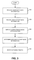
- FIG. 3 is a flowchart that illustrates an exemplary method for implementing simple shared shaping consistent with principles of the invention.
- FIG. 1 illustrates an exemplary system that may be used to implement simple shared shaping consistent with principles of the invention.
- System 100 may include a network device 102 , a network 104 and a destination device 106 .
- Network device 102 may be connected to other devices and may include any device capable of placing data units on a network.
- network device 102 may include a device, such as a router, a switch, a server, a personal computer, an intrusion detection device, and/or a firewall.
- Data unit as used herein, may refer to any type of machine-readable data having substantially any format that may be adapted for use with network 104 .
- a data unit may include packet and/or non-packet formats.
- Network device 102 may receive incoming data units from network 104 and/or another device and may make outgoing data units available to network 104 via an interface.
- Network device 102 may be configured to perform data unit operations and/or functions such as scheduling, forwarding, and/or switching.
- Network 104 may include any type of network capable of receiving a data unit.
- Network 104 may include a number of network devices, such as routers, switches, gateways and/or databases, for transporting data units from a source device, such as network device 102 , to a destination device, such as destination device 106 .
- Network 104 may include physical links for transporting data units from a source to a destination. Physical links may include wired and/or wireless links and/or may include one or more logical interfaces, such as virtual circuits.
- Network 104 may operate via substantially any network protocol or combination of network protocols, such as Internet Protocol (IP), asynchronous transfer mode (ATM), and/or synchronous optical transport (SONET).
- IP Internet Protocol
- ATM asynchronous transfer mode
- SONET synchronous optical transport
- Destination device 106 may include any device capable of receiving a data unit from network 104 and/or transmitting a data unit to network 104 .
- Destination device 106 may include a network device, such as a device similar to network device 102 , a desktop computer, a server, a laptop computer, and/or a handheld computing device, such as a personal digital assistant (PDA) and/or web-enabled cellular telephone.
- PDA personal digital assistant
- FIG. 2 illustrates an exemplary architecture that may be used in network device 102 to facilitate simple shared shaping consistent with the principles of the invention.
- the implementation of FIG. 2 may include a control unit 202 , a network interface 204 , a memory 206 that may include an input queue 208 , a scheduler 210 , and a simple shared shaper 212 , and an interconnect 214 .
- Control unit 202 may include any type of processor, or microprocessor, or processing logic that interprets and executes instructions. Control unit 202 may be implemented in a standalone and/or a distributed configuration, such as in a parallel processing implementation. Control unit 202 may be implemented as an application specific integrated circuit (ASIC) consistent with the principles of the invention. Control unit 202 may perform high level management functions for network device 102 , such as creating data unit forwarding lists, processing simple shared shaper inputs, interacting with scheduler 210 , and/or monitoring the status of input queue 208 .
- ASIC application specific integrated circuit
- Network interface 204 may include any device capable of receiving data units from and/or making data units available to network 104 .
- network interface 204 may receive a data unit from a physical link and may make the data unit available to control unit 202 for processing.
- Network interface 204 may receive the processed data unit and/or another data unit from control unit 202 and may make the processed data unit available to a physical link associated with network 104 .
- a physical link may include one or more logical interfaces, such as virtual circuits, which may include a group of virtual circuits.
- a physical link may also include one or more virtual paths. Data units received via network interface 204 may be processed and shaped before network interface 204 makes them available to a link.
- Memory 206 may include any device capable of storing information and/or instructions.
- memory 206 may include a random access memory (RAM) or another type of dynamic storage device that stores information and instructions for execution by control unit 202 .
- RAM random access memory
- Memory 206 may also be used to store temporary variables and/or other intermediate information during execution of instructions by control unit 202 .
- memory 206 may store incoming data units and/or outgoing data units.
- Memory 206 may operate in cooperation with other storage devices, such as a magnetic disk or optical storage media and its corresponding drive, for storing information and/or instructions.
- memory 206 may store instructions that are used to process incoming traffic, information associated with incoming traffic, processed traffic, and queued outgoing traffic prior to making it available to network interface 204 .
- Input queue 208 may include hardware and/or software for monitoring and/or buffering data traffic flows within network device 102 .
- input queue 208 may include one or more queues for buffering voice traffic, video traffic and/or data traffic.
- Input queue 208 may operate in conjunction with memory 206 .
- Input queue 208 may operate in conjunction with one or more determined traffic parameters, such as delay and/or jitter. For example, a first input queue associated with voice traffic may operate as a high priority queue according to stringent delay and/or jitter requirements, a second queue associated with video traffic may operate as a medium priority queue with less stringent delay and/or jitter requirements, and a third queue associated with data traffic may operate as a low priority queue having a best effort requirement.
- Input queue 208 may operate in conjunction with another queue (not shown), such as a best effort or aggregate queue.
- a best effort queue may be a queue configured to operate without regard to requirements/priorities associated with portions of the traffic, such as delay and/or jitter requirements/priorities.
- An aggregate queue may refer to a queue that receives traffic from a number of input sources and/or other queues and manages the received traffic via a single queue.
- Scheduler 210 may include hardware and/or software for scheduling data units arriving at network device 102 and/or scheduling the egress of data units from network device 102 .
- Scheduler 210 may operate alone or in cooperation with other scheduling devices and/or techniques, such as a hierarchical scheduler, to forward traffic according to a priority established for a class of traffic, such as voice, video, and/or data traffic.
- Scheduler 210 may employ aggregate rate information associated with incoming traffic flows and/or queue information to forward traffic via one or more logical interfaces.
- Scheduler 210 may operate in conjunction with control unit 202 , input queue 208 and/or simple shared shaper 212 to facilitate management of traffic coming into and/or going out of network device 102 .
- incoming data units may arrive at input queue 208 after being received at network device 102 via network interface 204 .
- Incoming data units may be associated with one or more priorities.
- Scheduler 210 may operate on prioritized data units in conjunction with simple shared shaper 212 to make them available to a physical link via network interface 204 . For example, incoming voice data units may be assigned a high priority while data units associated with still images may be assigned a lower priority.
- Input queue 208 may receive the prioritized incoming data units and may make them available to other devices, such as scheduler 210 .
- Scheduler 210 may operate to empty input queue 208 based on the priorities assigned to the incoming data units.
- Simple shared shaper 212 may include software and/or hardware for implementing dynamic traffic shaping of incoming and/or outgoing traffic flows. Dynamic traffic shaping may include prioritizing traffic according to determined parameters, such as delay and/or jitter, and/or low/medium/high priority, and/or may include substantially maintaining an aggregated traffic flow at a predetermined rate. Dynamic traffic shaping may facilitate efficient use and/or reuse of bandwidth associated with network interface 204 . Implementations of simple shared shaper 212 may take into account the operating characteristics of other devices, such as a downstream queue, when performing dynamic traffic shaping. For example, simple shared shaper 212 may avoid overrunning the downstream queue by managing the aggregate traffic flow so as not to exceed a throughput rate associated with the downstream queue.
- Simple shared shaper 212 may operate on voice, video and/or data traffic associated with input queue 208 so as to maintain an aggregated bandwidth at a determined rate.
- Simple shared shaper 212 may receive non-aggregated flows, such as voice, video and/or data, and may produce a shaped aggregated flow that represents a combination of the non-aggregated flows.
- network device 102 may operate to maintain a subscriber's virtual circuit at an aggregate output bandwidth of 10 Mbits/sec.
- the aggregate bandwidth may be specified to maintain delay/jitter within predetermined limits for high priority traffic, such as voice traffic.
- This 10 Mbit/sec aggregate bandwidth may be based on an estimated traffic rate of 2 Mbits/sec for high priority voice traffic, 5 Mbits/sec for medium priority video traffic, and 3 Mbits/sec for low priority data traffic.
- 2 Mbits/sec, 5 Mbits/sec, and 3 Mbits/sec may represent thresholds, or upper limits, for voice traffic, video traffic, and data traffic, respectively.
- voice traffic is operating below its allocated bandwidth at a rate of, for example, 0.5 Mbits/sec
- simple shared shaper 212 may allocate the unused high priority bandwidth of 1.5 Mbits/sec among the other traffic flows, such as video and/or data.
- 1.5 Mbits/sec of voice traffic bandwidth may be dynamically re-allocated so as to maintain the aggregate traffic flow at 10 Mbits/sec on the virtual circuit.
- Simple shared shaper 212 may be configured to minimize and/or eliminate overshoots that may occur if a traffic rate exceeds its threshold.
- voice traffic may be 0.5 Mbits/sec when sampled at a first sampling interval.
- voice traffic may have increased to 2.5 Mbits/sec.
- the increase in voice traffic above the 2.0 Mbit/sec threshold may be referred to as an overshoot of 0.5 Mbits/sec.
- simple shared shaper 212 may be configured to dynamically reallocate a portion of the video traffic to another traffic flow, such as video and/or data, in order to facilitate maintaining an aggregate traffic flow at a determined rate, such as 10 Mbits/sec.
- Simple shared shaper 212 may receive best effort rate information from memory 206 (act 304 ). Best effort rate information may include a best effort value associated with a previous sample. For example, the output of simple shared shaper 212 for a given sampling interval may be a best effort rate. A best effort rate for a sampling interval, t, may be used as an input to simple shared shaper 212 for a subsequent sampling interval, such as interval t+1. Best effort rate information may include a representation of the actual best effort rate associated with simple shared shaper 212 at a prior sampling interval. Implementations of simple shared shaper 212 may operate with a single best effort rate value or with multiple best effort rate values. Multiple best effort rate values may be used to adjust reactivity of the shared shaper and its frequency response.
- Simple shared shaper 212 may operate with downstream devices that perform scheduling and/or rate limiting functions.
- Simple shared shaper 212 may take a parameter, such as the performance, associated with a downstream device into account when shaping traffic flows so that a traffic flow in a queue associated with a downstream device does not exceed a threshold, such as an input traffic flow limit. Increases in queue length may lead to delay, such as a delay associated with the amount of time it takes for a data unit to go from the top of a downstream queue to the bottom of that queue, where the bottom of the downstream queue corresponds to an egress port for the queue.
- scheduler 210 and/or simple shared shaper 212 may operate with a downstream device having a queue associated therewith, such as a downstream segmentation and reassembly scheduler (SAR). It may be advantageous for simple shared shaper 212 to take the operation of the SAR into account in order to minimize the chances of overrunning the SAR queue, (i.e., filling the SAR queue faster that the queue can drain).
- SAR segmentation and reassembly scheduler
- Simple shared shaper 212 may employ a downstream queue approximation to reduce and/or eliminate the risk of overrunning a downstream queue (act 306 ).
- An approximation may be used for the downstream queue since no actual communication, or feedback, may exist between simple shared shaper 212 and the downstream device.
- the downstream queue approximation may be obtained via modeling, network measurements, and/or design parameters, such as by configuring an aggregate queue on network device 102 to match a configuration of a downstream queue associated with, for example, a SAR.
- Simple shared shaper 212 may process information and/or approximations to arrive at a new best effort rate value (act 308 ).
- simple shared shaper 212 may use non-aggregated flows, such as voice, video and data, best effort rate information from a previous sampling interval, a downstream queue length approximation, and/or a shared shaping rate, to determine the best effort rate value.
- a shared shaping rate may be provided to simple shared shaper 212 as a constant value.
- Simple shared shaper 212 may shape outgoing traffic in a manner that minimizes and/or eliminates overshoots (act 310 ). For example, if a measured aggregate rate of non-best effort traffic increases from one sampling interval to another, simple shared shaper 212 may operate to reduce the available bandwidth for non-best effort traffic to minimize the chances of overshoot and/or exceeding an allocated bandwidth threshold associated with an interface. In contrast, if an available bandwidth is increasing because an aggregate traffic flow is below a threshold, simple shared shaper 212 may provision additional traffic in a manner that minimizes the potential for overshoot, such as by slightly under-provisioning the additional bandwidth.
- an available best effort shaping rate at a time t N may be represented as
- R N (A) may be characterized as the difference between the configured shared shaping rate (SSR) and the rate of all traffic flows aggregated into simple shared shaper 212 , excluding best effort traffic, averaged over the previous sampling period R N (M) .
- ⁇ k and ⁇ k may represent weights associated with prior samples.
- ⁇ k and ⁇ k may be time-dependent in implementations of simple shared shaper 212 consistent with the principles of the invention.
- Implementations of simple shared shaper 212 may employ normalized values for ⁇ k and ⁇ k , such that
- a N may represent an adjustment and/or the combination of higher-order corrections to the best effort rate and may be represented as
- q N ⁇ ⁇ ⁇ t ⁇ ( R N - 1 - R N ( A ) ) ( Eq . ⁇ 6 )
- q N may be interpreted as the excess traffic passed through simple shared shaper 212 during the time interval (t N-1 , t N ).
- Downstream queues such as a SAR queue, may be configured to match the configured shared shaping rate associated with simple shared shaper 212 so that Q N may represent an approximation of the downstream queue depth at a time t N .
- a N may be an adjustment to the best effort rate based on a current and/or historic length of the downstream queue. Since the length of a downstream queue may be proportional to latency introduced by simple shared shaper 212 , A N may provide coupling of the best effort rate to latency.
- the first term of Eq. 7 may represent a mean for the new maximum possible best effort rate based on the latest measured rates through other devices and the previous best effort rate.
- the first term of Eq. 7 may provide shared shaping in that the best effort traffic may receive at least one half of the currently available bandwidth and the rate will be at least one half of the rate during the previous sampling period.
- the first term of Eq. 7 may provide protection against sudden changes in the available bandwidth and may dampen high frequency oscillations.
- the first term of Eq. 7, operating alone, may not be sufficient to restore latency promptly if an overshoot occurs.
- the second and third terms of Eq. 7 may compensate to facilitate prompt restoration of latency after an overshoot.
- the second and third terms of Eq. 7 may further operate on short and long time scales, respectively.
- the second term of Eq. 7 may operate to boost the best effort rate when the available bandwidth increases, while operating to reduce the best effort rate when the available bandwidth decreases.
- the third term of Eq. 7 may operate to reduce the best effort rate in the event that the approximated queue length of a downstream device is non-zero.
- network device 102 may operate on more than three types of traffic, more or fewer levels and/or classes of traffic, multiple simple shared shapers may operate in series and/or in parallel, and/or simple shared shapers may operate without a downstream queue length approximation.
Abstract
A method for sharing an aggregate bandwidth among a group of traffic classes may include allocating a portion of the aggregate bandwidth to one of the group of traffic classes having a first priority associated therewith, where the allocated portion is referred to as a first bandwidth. The method may include allocating an unused portion of the aggregate bandwidth to a second one of the group of traffic classes having a second priority associated therewith in conjunction with a parameter associated with a downstream device.
Description
This application is a continuation of U.S. patent application Ser. No. 11/206,786 filed Aug. 19, 2005, which is incorporated herein by reference.
Implementations consistent with the principles of the invention relate generally to network communication and, more particularly, to sharing bandwidth among different priorities or classes of network traffic.
Service providers may configure networks to deliver network traffic over a path having a bandwidth. Service providers may want to configure networks to efficiently use the available bandwidth to meet the needs of their subscribers. For example, a subscriber may send different types, or classes, of traffic across a network, such as voice traffic, video traffic and/or data traffic. The subscriber may require that various classes of traffic be handled differently. In the above example, voice traffic may be prone to distortion when delayed between a sending device and a receiving device. In contrast, data traffic may be relatively insensitive to delay. As a result, a subscriber may wish to have voice traffic treated with a higher priority as compared to data traffic.
Service providers may configure networks to treat classes of traffic according to differing delivery requirements to facilitate efficient utilization of bandwidth. For example, service providers may configure networks to assign a best effort or a lower priority to data traffic and a higher priority to time-sensitive traffic, such as voice and/or video traffic.
Service providers may configure network devices to facilitate efficient traffic management in networks. For example, a network device may be configured to implement a scheduler to schedule the forwarding of traffic via logical interfaces according to the traffic's associated priority. A logical interface may be, for example, a virtual circuit (VC). The service provider may allocate bandwidth on the logical interface based on an anticipated volume for each class of traffic, such as, for example, voice, video, and/or data classes. A scheduler may try to shape traffic so as to ensure that no traffic class exceeds its portion of the overall bandwidth for the VC. This type of traffic shaping may cause the allocated bandwidth to be underutilized if a class of traffic, such as voice, is operating below its allocated threshold.
In accordance with an implementation, a method for sharing an aggregate bandwidth among a group of traffic classes is provided. The method may include allocating a portion of the aggregate bandwidth to one of the group of traffic classes having a first priority associated therewith, where the allocated portion is referred to as a first bandwidth. The method may include allocating an unused portion of the aggregate bandwidth to a second one of the group of traffic classes having a second priority associated therewith in conjunction with a parameter associated with a downstream device.
In accordance with another implementation, a device for implementing shared shaping is provided. The device may include a processor adapted to determine a new best effort rate value in association with rate information associated with a group of traffic classes, a best effort rate value, and a shared shaping rate. The processor may be adapted to shape an aggregate traffic flow that includes the group of traffic classes, where shaping the aggregate traffic flow operates to discourage exceeding a rate limit.
In accordance with yet another implementation, a device for shared shaping is provided. The device may include means for storing information about a group of traffic classes, a prior downstream queue length approximation, and a prior best effort rate value. The shared shaper may include means for shaping an aggregate traffic flow that includes the group of traffic classes based at least in part on the new best effort rate, where the shaped aggregate traffic flow is adapted to discourage overrunning a downstream queue.
The accompanying drawings, which are incorporated in and constitute a part of this specification, illustrate an embodiment of the invention and, together with the description, explain the invention. In the drawings,
The following detailed description of the invention refers to the accompanying drawings. The same reference numbers in different drawings may identify the same or similar elements. Also, the following detailed description does not limit the invention. Instead, the scope of the invention is defined by the appended claims.
Network 104 may include any type of network capable of receiving a data unit. Network 104 may include a number of network devices, such as routers, switches, gateways and/or databases, for transporting data units from a source device, such as network device 102, to a destination device, such as destination device 106. Network 104 may include physical links for transporting data units from a source to a destination. Physical links may include wired and/or wireless links and/or may include one or more logical interfaces, such as virtual circuits. Network 104 may operate via substantially any network protocol or combination of network protocols, such as Internet Protocol (IP), asynchronous transfer mode (ATM), and/or synchronous optical transport (SONET).
Simple shared shaper 212 may include software and/or hardware for implementing dynamic traffic shaping of incoming and/or outgoing traffic flows. Dynamic traffic shaping may include prioritizing traffic according to determined parameters, such as delay and/or jitter, and/or low/medium/high priority, and/or may include substantially maintaining an aggregated traffic flow at a predetermined rate. Dynamic traffic shaping may facilitate efficient use and/or reuse of bandwidth associated with network interface 204. Implementations of simple shared shaper 212 may take into account the operating characteristics of other devices, such as a downstream queue, when performing dynamic traffic shaping. For example, simple shared shaper 212 may avoid overrunning the downstream queue by managing the aggregate traffic flow so as not to exceed a throughput rate associated with the downstream queue.
Simple shared shaper 212 may operate on voice, video and/or data traffic associated with input queue 208 so as to maintain an aggregated bandwidth at a determined rate. Simple shared shaper 212 may receive non-aggregated flows, such as voice, video and/or data, and may produce a shaped aggregated flow that represents a combination of the non-aggregated flows. For example, network device 102 may operate to maintain a subscriber's virtual circuit at an aggregate output bandwidth of 10 Mbits/sec. The aggregate bandwidth may be specified to maintain delay/jitter within predetermined limits for high priority traffic, such as voice traffic. This 10 Mbit/sec aggregate bandwidth may be based on an estimated traffic rate of 2 Mbits/sec for high priority voice traffic, 5 Mbits/sec for medium priority video traffic, and 3 Mbits/sec for low priority data traffic. In this example, 2 Mbits/sec, 5 Mbits/sec, and 3 Mbits/sec may represent thresholds, or upper limits, for voice traffic, video traffic, and data traffic, respectively. If voice traffic is operating below its allocated bandwidth at a rate of, for example, 0.5 Mbits/sec, simple shared shaper 212 may allocate the unused high priority bandwidth of 1.5 Mbits/sec among the other traffic flows, such as video and/or data. 1.5 Mbits/sec of voice traffic bandwidth may be dynamically re-allocated so as to maintain the aggregate traffic flow at 10 Mbits/sec on the virtual circuit.
Simple shared shaper 212 may be configured to minimize and/or eliminate overshoots that may occur if a traffic rate exceeds its threshold. Referring to the example used above, voice traffic may be 0.5 Mbits/sec when sampled at a first sampling interval. At a second sampling interval, voice traffic may have increased to 2.5 Mbits/sec. The increase in voice traffic above the 2.0 Mbit/sec threshold may be referred to as an overshoot of 0.5 Mbits/sec. In this case, simple shared shaper 212 may be configured to dynamically reallocate a portion of the video traffic to another traffic flow, such as video and/or data, in order to facilitate maintaining an aggregate traffic flow at a determined rate, such as 10 Mbits/sec.
Simple shared shaper 212 may receive best effort rate information from memory 206 (act 304). Best effort rate information may include a best effort value associated with a previous sample. For example, the output of simple shared shaper 212 for a given sampling interval may be a best effort rate. A best effort rate for a sampling interval, t, may be used as an input to simple shared shaper 212 for a subsequent sampling interval, such as interval t+1. Best effort rate information may include a representation of the actual best effort rate associated with simple shared shaper 212 at a prior sampling interval. Implementations of simple shared shaper 212 may operate with a single best effort rate value or with multiple best effort rate values. Multiple best effort rate values may be used to adjust reactivity of the shared shaper and its frequency response.
Implementations of simple shared shaper 212 may operate with downstream devices that perform scheduling and/or rate limiting functions. Simple shared shaper 212 may take a parameter, such as the performance, associated with a downstream device into account when shaping traffic flows so that a traffic flow in a queue associated with a downstream device does not exceed a threshold, such as an input traffic flow limit. Increases in queue length may lead to delay, such as a delay associated with the amount of time it takes for a data unit to go from the top of a downstream queue to the bottom of that queue, where the bottom of the downstream queue corresponds to an egress port for the queue. For example, if network device 102 operates in an ATM network, scheduler 210 and/or simple shared shaper 212 may operate with a downstream device having a queue associated therewith, such as a downstream segmentation and reassembly scheduler (SAR). It may be advantageous for simple shared shaper 212 to take the operation of the SAR into account in order to minimize the chances of overrunning the SAR queue, (i.e., filling the SAR queue faster that the queue can drain).
Simple shared shaper 212 may employ a downstream queue approximation to reduce and/or eliminate the risk of overrunning a downstream queue (act 306). An approximation may be used for the downstream queue since no actual communication, or feedback, may exist between simple shared shaper 212 and the downstream device. The downstream queue approximation may be obtained via modeling, network measurements, and/or design parameters, such as by configuring an aggregate queue on network device 102 to match a configuration of a downstream queue associated with, for example, a SAR.
Simple shared shaper 212 may process information and/or approximations to arrive at a new best effort rate value (act 308). For example, simple shared shaper 212 may use non-aggregated flows, such as voice, video and data, best effort rate information from a previous sampling interval, a downstream queue length approximation, and/or a shared shaping rate, to determine the best effort rate value. For example, a shared shaping rate may be provided to simple shared shaper 212 as a constant value.
Simple shared shaper 212 may shape outgoing traffic in a manner that minimizes and/or eliminates overshoots (act 310). For example, if a measured aggregate rate of non-best effort traffic increases from one sampling interval to another, simple shared shaper 212 may operate to reduce the available bandwidth for non-best effort traffic to minimize the chances of overshoot and/or exceeding an allocated bandwidth threshold associated with an interface. In contrast, if an available bandwidth is increasing because an aggregate traffic flow is below a threshold, simple shared shaper 212 may provision additional traffic in a manner that minimizes the potential for overshoot, such as by slightly under-provisioning the additional bandwidth.
The method described in conjunction with FIG. 3 may be implemented in software in one implementation consistent with the principles of the invention. For example, an available best effort shaping rate at a time tN may be represented as
with,
R N=max({circumflex over (R)} N,0)
where RN equals a best effort shaping rate at time tN, L may represent the number of samples evaluated by simple shared
R N (A)=SSR−R N (M) (Eq. 2)
αk and βk may represent weights associated with prior samples. αk and βk may be time-dependent in implementations of simple shared shaper 212 consistent with the principles of the invention. Implementations of simple shared shaper 212 may employ normalized values for αk and βk, such that
αk and βk may be found via simulation, approximation, and/or via traffic measurements performed on
AN may represent an adjustment and/or the combination of higher-order corrections to the best effort rate and may be represented as
qN may be interpreted as the excess traffic passed through simple shared
Downstream queues, such as a SAR queue, may be configured to match the configured shared shaping rate associated with simple shared shaper 212 so that QN may represent an approximation of the downstream queue depth at a time tN. When this occurs, AN may be an adjustment to the best effort rate based on a current and/or historic length of the downstream queue. Since the length of a downstream queue may be proportional to latency introduced by simple shared shaper 212, AN may provide coupling of the best effort rate to latency.
An exemplary implementation of simple shared shaper 212, consistent with the principles of the invention, may be implemented with the following parameters,
L=1,α0= 5/2,α1=−2,β1=½,γ1=−½
Eq. 1 may be rewritten using the above parameters as
{circumflex over (R)} N=½(R N (A) +R N-1)+2·(R N (A) −R N-1 (A))−½Q N-1 (Eq. 7)
L=1,α0= 5/2,α1=−2,β1=½,γ1=−½
Eq. 1 may be rewritten using the above parameters as
{circumflex over (R)} N=½(R N (A) +R N-1)+2·(R N (A) −R N-1 (A))−½Q N-1 (Eq. 7)
where the first term of Eq. 7 may represent a mean for the new maximum possible best effort rate based on the latest measured rates through other devices and the previous best effort rate. The first term of Eq. 7 may provide shared shaping in that the best effort traffic may receive at least one half of the currently available bandwidth and the rate will be at least one half of the rate during the previous sampling period. Furthermore, the first term of Eq. 7 may provide protection against sudden changes in the available bandwidth and may dampen high frequency oscillations.
The first term of Eq. 7, operating alone, may not be sufficient to restore latency promptly if an overshoot occurs. The second and third terms of Eq. 7 may compensate to facilitate prompt restoration of latency after an overshoot. The second and third terms of Eq. 7 may further operate on short and long time scales, respectively. The second term of Eq. 7 may operate to boost the best effort rate when the available bandwidth increases, while operating to reduce the best effort rate when the available bandwidth decreases. The third term of Eq. 7 may operate to reduce the best effort rate in the event that the approximated queue length of a downstream device is non-zero.
The foregoing description describes implementations of a simple shared shaper that may be configured to shape bandwidth and/or share unused bandwidth among traffic flows having different priorities. The foregoing description of exemplary embodiments of the present invention provides illustration and description, but is not intended to be exhaustive and/or to limit the invention to the precise form disclosed. Modifications and/or variations are possible in light of the above teachings and/or may be acquired from practice of the invention. For example, configurations other than those described may be possible. For example, network device 102 may operate on more than three types of traffic, more or fewer levels and/or classes of traffic, multiple simple shared shapers may operate in series and/or in parallel, and/or simple shared shapers may operate without a downstream queue length approximation.
While series of acts have been described with regard to FIG. 3 , the order of the acts is not critical. No element, act, or instruction used in the description of the present application should be construed as critical or essential to the invention unless explicitly described as such. Also, as used herein, the article “a” is intended to include one or more items. Where only one item is intended, the term “one” or similar language is used. Further, the phrase “based on” as used herein is intended to mean “based, at least in part, on” unless explicitly stated otherwise.
The scope of the invention is defined by the following claims and their equivalents.
Claims (17)
1. a method performed by a network device, the method comprising: allocating, by a control unit of the network device, a portion of an aggregate bandwidth to one of a plurality of traffic classes of traffic entering the network device, the aggregate bandwidth associated with a best effort rate value; determining, by the control unit and without communicating with a downstream device, an approximation of a length of a queue associated with the downstream device; determining, by the control unit, a new best effort rate based on the approximation of the length of the queue associated with the downstream device and the best effort rate value; shaping, by the control unit and based on the new best effort rate, an outgoing traffic flow associated with the network device, the outgoing traffic flow including best effort rate traffic; and allocating, by the control unit and based on the approximation of the length of the queue associated with the downstream device, an unused portion of the aggregate bandwidth to another one of the plurality of traffic classes determined to be exceeding an associated portion of the aggregate bandwidth, the one of the plurality of traffic classes associated with a first priority and the other one of the plurality of traffic classes associated with a second priority, the second priority being a higher priority than the first priority.
2. The method of claim 1 , further comprising:
obtaining, by the control unit, aggregate rate information associated with the aggregate bandwidth, the aggregate rate information including a first rate of a traffic flow of the traffic associated with the one of the plurality of traffic classes and a second rate of a traffic flow of the traffic associated with the other one of the plurality of traffic classes; and
where determining the new best effort rate value is further based on the obtained aggregate rate information.
3. The method of claim 2 , where obtaining the aggregate rate information, further comprises
sampling an input queue of the network device.
4. The method of claim 1 , where determining the approximation of the length of the queue associated with the downstream device, further comprises:
determining the approximation of the length of the queue associated with the downstream device based on a previous approximation of a length of the queue associated with the downstream device.
5. the method of claim 1 , where prior to the allocating the unused portion of the aggregated bandwidth, the method further comprises: determining that the other one of the plurality of traffic classes exceeds the associated portion of the aggregate bandwidth.
6. A network device comprising:
one or more queues to:
receive a first class of traffic associated with a first priority, the first priority representing a first quality of service requirement,
receive a second class of traffic associated with a second priority, the second priority representing a second quality of service requirement; and
a control unit to:
allocate, based on the first quality of service requirement represented by the first priority, a first portion of an aggregate bandwidth to the first class of traffic,
allocate, based on the second quality of service requirement represented by the second priority, a second portion of the aggregate bandwidth to the second class of traffic,
determine a best effort rate value associated with the aggregate bandwidth,
determine, without communicating with a downstream device, an approximation of a length of a first queue, of the one or more queues, associated with the downstream device,
determine a new best effort rate value based on the approximation of the length of the first queue and the best effort rate value, and
allocate, based on the approximation of the length of the first queue and the second quality of service represented by the second priority, an unused portion of the first portion of the aggregate bandwidth to the second traffic class, the second traffic class determined to be exceeding the second portion of the aggregate bandwidth.
7. The network device of claim 6 , where the control unit is further to:
obtain aggregate rate information that includes a first traffic flow rate associated with the first class of traffic and a second traffic flow rate associated with the second class of traffic, and
where the new best effort rate value is determined further based on the obtained aggregate rate information.
8. The network device of claim 7 , where the control unit is further to:
sample the at least one of the one or more queues to obtain the aggregate rate information.
9. The network device of claim 6 , where the approximation of the length of the first queue is based on a previous approximation of a length of the first queue.
10. The network device of claim 6 , where the control unit is further to:
shape an outgoing traffic flow associated with the network device, based on the new best effort rate value, where the outgoing traffic includes best effort rate traffic, a first traffic flow, and a second traffic flow, where the first traffic flow and the second traffic flow include the first quality of service requirement and the second quality of service requirement, respectively.
11. The network device of claim 6 , where prior to the allocation of the unused portion of the first portion of the aggregate bandwidth, the control unit is further to:
determine that the second class of traffic exceeds the second portion of the aggregate bandwidth.
12. The network device of claim 6 , where, when determining the new best effort rate value, the control unit is further to:
determine the new best effort rate value further based on an available bandwidth at a current time period and an earlier best effort rate value associated with an earlier time period multiplied by a first coefficient.
13. a system comprising: a network device to: obtain aggregate rate information for network traffic entering the network; identify a first best effort rate value, approximate a downstream queue length associated with a downstream device based on an amount of traffic flow associated with a first traffic class of the network traffic that exceeds a first threshold amount of traffic flow and a prior determination of the downstream queue length, determine a second best effort rate value based on the approximated downstream queue length, the aggregate rate information, and the first best effort rate value, and shape, based on the second best effort rate value, an outgoing traffic flow of the network traffic associated with the network device that includes best effort rate traffic, a first traffic flow associated with the first traffic class, and a second traffic flow associated with the second traffic class, the first traffic flow including a first quality of service requirement associated with the first traffic class, and the second traffic flow including a second quality of service requirement associated with a second quality of service requirement.
14. The system of claim 13 , where, when shaping the outgoing traffic flow of the network traffic, the network device is further to:
shape the outgoing traffic flow of the network traffic to maintain an aggregate amount of the outgoing traffic flow at a constant amount of traffic flow.
15. The system of claim 13 , where the network device is further to:
sample an input queue of the network device to obtain the aggregate rate information.
16. the system of claim 13 , where network device is further to: reallocate, based on the first threshold amount of traffic flow, an unused portion of bandwidth associated with the first traffic class to allow the second traffic class to exceed a second threshold amount of traffic flow.
17. The system of claim 13 , where the network device is further to:
determine the second best effort rate value further based on an available bandwidth at a current time period and a third best effort rate value associated with an earlier time period multiplied by a first coefficient.
Priority Applications (1)
| Application Number | Priority Date | Filing Date | Title |
|---|---|---|---|
| US12/771,916 US8218437B2 (en) | 2005-08-19 | 2010-04-30 | Shared shaping of network traffic |
Applications Claiming Priority (2)
| Application Number | Priority Date | Filing Date | Title |
|---|---|---|---|
| US11/206,786 US7738375B1 (en) | 2005-08-19 | 2005-08-19 | Shared shaping of network traffic |
| US12/771,916 US8218437B2 (en) | 2005-08-19 | 2010-04-30 | Shared shaping of network traffic |
Related Parent Applications (1)
| Application Number | Title | Priority Date | Filing Date |
|---|---|---|---|
| US11/206,786 Continuation US7738375B1 (en) | 2005-08-19 | 2005-08-19 | Shared shaping of network traffic |
Publications (2)
| Publication Number | Publication Date |
|---|---|
| US20100208588A1 US20100208588A1 (en) | 2010-08-19 |
| US8218437B2 true US8218437B2 (en) | 2012-07-10 |
Family
ID=42237633
Family Applications (2)
| Application Number | Title | Priority Date | Filing Date |
|---|---|---|---|
| US11/206,786 Active 2027-07-01 US7738375B1 (en) | 2005-08-19 | 2005-08-19 | Shared shaping of network traffic |
| US12/771,916 Active US8218437B2 (en) | 2005-08-19 | 2010-04-30 | Shared shaping of network traffic |
Family Applications Before (1)
| Application Number | Title | Priority Date | Filing Date |
|---|---|---|---|
| US11/206,786 Active 2027-07-01 US7738375B1 (en) | 2005-08-19 | 2005-08-19 | Shared shaping of network traffic |
Country Status (1)
| Country | Link |
|---|---|
| US (2) | US7738375B1 (en) |
Cited By (1)
| Publication number | Priority date | Publication date | Assignee | Title |
|---|---|---|---|---|
| US10911363B2 (en) | 2019-03-29 | 2021-02-02 | At&T Intellectual Property I, L.P. | Method and apparatus for performing file shaping |
Families Citing this family (22)
| Publication number | Priority date | Publication date | Assignee | Title |
|---|---|---|---|---|
| US7839876B1 (en) | 2006-01-25 | 2010-11-23 | Marvell International Ltd. | Packet aggregation |
| JP4658098B2 (en) * | 2006-11-21 | 2011-03-23 | 日本電信電話株式会社 | Flow information limiting apparatus and method |
| US8553573B2 (en) * | 2007-04-13 | 2013-10-08 | Hewlett-Packard Development Company, L.P. | Apparatus and method for adaptive throttling of traffic across multiple network nodes |
| US8050289B1 (en) * | 2008-02-01 | 2011-11-01 | Zenverge, Inc. | Media transmission using aggregated bandwidth of disparate communication channels |
| US8611239B2 (en) * | 2009-05-22 | 2013-12-17 | Qualcomm Incorporated | Distributed computation of common normalization constant for quantized best effort traffic priority |
| US8693332B2 (en) * | 2009-06-30 | 2014-04-08 | New Renaissance Technology And Intellectual Property | Flow state aware management of QoS through dynamic aggregate bandwidth adjustments |
| EP2484057A4 (en) * | 2009-10-01 | 2016-01-27 | Entropic Communications Inc | System and method for a managed network with quality-of-service |
| US9042311B2 (en) * | 2010-03-05 | 2015-05-26 | Intel Corporation | Techniques for evaluation and improvement of user experience for applications in mobile wireless networks |
| US10187496B2 (en) * | 2010-12-14 | 2019-01-22 | Comcast Cable Communications, Llc | Apparatus, system and method for resolving bandwidth constriction |
| US9491735B2 (en) * | 2010-12-19 | 2016-11-08 | Motorola Solutions, Inc. | System and method in a communication network of dynamically assigning a multimedia broadcast/multicast service bearer to a multicast channel |
| US20140153388A1 (en) * | 2012-11-30 | 2014-06-05 | Hewlett-Packard Development Company, L.P. | Rate limit managers to assign network traffic flows |
| US20140160945A1 (en) * | 2012-12-06 | 2014-06-12 | Accedian Networks Inc. | Using bandwidth measurements to adjust cir and eir on a sub-rate link |
| US9510232B2 (en) | 2014-07-09 | 2016-11-29 | T-Mobile Usa, Inc. | Cellular network backhaul oversubscription |
| JP2016024220A (en) * | 2014-07-16 | 2016-02-08 | 株式会社リコー | Display device, display program, and display system |
| US9749151B2 (en) | 2014-12-18 | 2017-08-29 | T-Mobile Usa, Inc. | Tunneling with routing for transport network |
| US9615287B2 (en) * | 2014-12-18 | 2017-04-04 | T-Mobile Usa, Inc. | Dynamic bandwidth scheduling with transport network |
| US9979663B2 (en) * | 2015-06-08 | 2018-05-22 | Accedian Networks Inc. | TCP performance predictor |
| CN108650235B (en) * | 2018-04-13 | 2021-06-04 | 北京网藤科技有限公司 | Intrusion detection device and detection method thereof |
| US11128536B2 (en) * | 2018-10-04 | 2021-09-21 | Sandvine Corporation | System and method for intent based traffic management |
| EP3920487A1 (en) | 2020-06-04 | 2021-12-08 | Sandvine Corporation | System and method for quality of experience management |
| US11901983B1 (en) * | 2021-03-17 | 2024-02-13 | T-Mobile Innovations Llc | Selectively assigning uplink transmission layers |
| US20230033532A1 (en) * | 2021-07-29 | 2023-02-02 | Dish Wireless L.L.C. | Method and system for aggregate maximum bit rate (ambr) management |
Citations (20)
| Publication number | Priority date | Publication date | Assignee | Title |
|---|---|---|---|---|
| US6064651A (en) | 1996-06-27 | 2000-05-16 | Xerox Corporation | Rate shaping in per-flow output queued routing mechanisms for statistical bit rate service |
| US6104698A (en) | 1995-10-31 | 2000-08-15 | Nec Corporation | Asynchronous transfer mode exchange system and priority control method |
| US20020110139A1 (en) * | 2001-02-15 | 2002-08-15 | Jihad Boura | Logical multicast packet handling |
| US6438138B1 (en) | 1997-10-01 | 2002-08-20 | Nec Corporation | Buffer controller incorporated in asynchronous transfer mode network for changing transmission cell rate depending on duration of congestion and method for controlling thereof |
| US20020114334A1 (en) * | 2001-02-21 | 2002-08-22 | Xuechen Yang | System and method for asymmetrical bandwidth management |
| US20030063562A1 (en) * | 2001-09-21 | 2003-04-03 | Terago Communications, Inc. | Programmable multi-service queue scheduler |
| US6549517B1 (en) | 1998-12-11 | 2003-04-15 | Nortel Networks Limited | Explicit rate computation for flow control in compute networks |
| US6636512B1 (en) | 1998-07-31 | 2003-10-21 | International Business Machines Corporation | System, method, and article of manufacture for increasing link bandwidth utilization in a high speed digital network |
| US20040018849A1 (en) * | 2002-07-23 | 2004-01-29 | Schiff Leornard N. | Queue length-based data transmission for wireless communication |
| US6687225B1 (en) | 1998-11-10 | 2004-02-03 | Fujitsu Limited | Bandwidth control apparatus |
| US20040081093A1 (en) | 1998-02-03 | 2004-04-29 | Haddock Stephen R. | Policy based quality of service |
| US20040085964A1 (en) | 2002-10-29 | 2004-05-06 | Janne Vaananen | Method and apparatus for scheduling available link bandwidth between packet-switched data flows |
| US20040114520A1 (en) | 2002-12-12 | 2004-06-17 | Alcatel Canada Inc. | Bandwidth management of resilient packet ring network |
| US20050044206A1 (en) | 2001-09-07 | 2005-02-24 | Staffan Johansson | Method and arrangements to achieve a dynamic resource distribution policy in packet based communication networks |
| US6973315B1 (en) * | 2001-07-02 | 2005-12-06 | Cisco Technology, Inc. | Method and system for sharing over-allocated bandwidth between different classes of service in a wireless network |
| US20060014544A1 (en) | 2002-11-08 | 2006-01-19 | Nokia Corporation | Method and a system for selecting non-real-time users to perform cell reselection |
| US20060018326A1 (en) | 2004-07-23 | 2006-01-26 | Marconi Communications, Inc. | LSP path selection |
| US7039013B2 (en) * | 2001-12-31 | 2006-05-02 | Nokia Corporation | Packet flow control method and device |
| US20060164989A1 (en) | 2005-01-24 | 2006-07-27 | Alcatel | Communication traffic management systems and methods |
| US7266122B1 (en) * | 2002-11-27 | 2007-09-04 | Genband Inc. | System and method for allocating bandwidth in a communications environment |
-
2005
- 2005-08-19 US US11/206,786 patent/US7738375B1/en active Active
-
2010
- 2010-04-30 US US12/771,916 patent/US8218437B2/en active Active
Patent Citations (20)
| Publication number | Priority date | Publication date | Assignee | Title |
|---|---|---|---|---|
| US6104698A (en) | 1995-10-31 | 2000-08-15 | Nec Corporation | Asynchronous transfer mode exchange system and priority control method |
| US6064651A (en) | 1996-06-27 | 2000-05-16 | Xerox Corporation | Rate shaping in per-flow output queued routing mechanisms for statistical bit rate service |
| US6438138B1 (en) | 1997-10-01 | 2002-08-20 | Nec Corporation | Buffer controller incorporated in asynchronous transfer mode network for changing transmission cell rate depending on duration of congestion and method for controlling thereof |
| US20040081093A1 (en) | 1998-02-03 | 2004-04-29 | Haddock Stephen R. | Policy based quality of service |
| US6636512B1 (en) | 1998-07-31 | 2003-10-21 | International Business Machines Corporation | System, method, and article of manufacture for increasing link bandwidth utilization in a high speed digital network |
| US6687225B1 (en) | 1998-11-10 | 2004-02-03 | Fujitsu Limited | Bandwidth control apparatus |
| US6549517B1 (en) | 1998-12-11 | 2003-04-15 | Nortel Networks Limited | Explicit rate computation for flow control in compute networks |
| US20020110139A1 (en) * | 2001-02-15 | 2002-08-15 | Jihad Boura | Logical multicast packet handling |
| US20020114334A1 (en) * | 2001-02-21 | 2002-08-22 | Xuechen Yang | System and method for asymmetrical bandwidth management |
| US6973315B1 (en) * | 2001-07-02 | 2005-12-06 | Cisco Technology, Inc. | Method and system for sharing over-allocated bandwidth between different classes of service in a wireless network |
| US20050044206A1 (en) | 2001-09-07 | 2005-02-24 | Staffan Johansson | Method and arrangements to achieve a dynamic resource distribution policy in packet based communication networks |
| US20030063562A1 (en) * | 2001-09-21 | 2003-04-03 | Terago Communications, Inc. | Programmable multi-service queue scheduler |
| US7039013B2 (en) * | 2001-12-31 | 2006-05-02 | Nokia Corporation | Packet flow control method and device |
| US20040018849A1 (en) * | 2002-07-23 | 2004-01-29 | Schiff Leornard N. | Queue length-based data transmission for wireless communication |
| US20040085964A1 (en) | 2002-10-29 | 2004-05-06 | Janne Vaananen | Method and apparatus for scheduling available link bandwidth between packet-switched data flows |
| US20060014544A1 (en) | 2002-11-08 | 2006-01-19 | Nokia Corporation | Method and a system for selecting non-real-time users to perform cell reselection |
| US7266122B1 (en) * | 2002-11-27 | 2007-09-04 | Genband Inc. | System and method for allocating bandwidth in a communications environment |
| US20040114520A1 (en) | 2002-12-12 | 2004-06-17 | Alcatel Canada Inc. | Bandwidth management of resilient packet ring network |
| US20060018326A1 (en) | 2004-07-23 | 2006-01-26 | Marconi Communications, Inc. | LSP path selection |
| US20060164989A1 (en) | 2005-01-24 | 2006-07-27 | Alcatel | Communication traffic management systems and methods |
Non-Patent Citations (1)
| Title |
|---|
| Co-pending U.S. Appl. No. 11/206,786, filed Aug. 19, 2005 entitled "Shared Shaping of Netowrk Traffic" by Vitali Vinokour et al., 25 pages. |
Cited By (1)
| Publication number | Priority date | Publication date | Assignee | Title |
|---|---|---|---|---|
| US10911363B2 (en) | 2019-03-29 | 2021-02-02 | At&T Intellectual Property I, L.P. | Method and apparatus for performing file shaping |
Also Published As
| Publication number | Publication date |
|---|---|
| US20100208588A1 (en) | 2010-08-19 |
| US7738375B1 (en) | 2010-06-15 |
Similar Documents
| Publication | Publication Date | Title |
|---|---|---|
| US8218437B2 (en) | Shared shaping of network traffic | |
| US10764215B2 (en) | Programmable broadband gateway hierarchical output queueing | |
| US6674718B1 (en) | Unified method and system for scheduling and discarding packets in computer networks | |
| US7142513B2 (en) | Method and multi-queue packet scheduling system for managing network packet traffic with minimum performance guarantees and maximum service rate control | |
| US8169906B2 (en) | Controlling ATM traffic using bandwidth allocation technology | |
| JP5340186B2 (en) | Packet relay apparatus and packet relay method | |
| US6795870B1 (en) | Method and system for network processor scheduler | |
| US7619969B2 (en) | Hardware self-sorting scheduling queue | |
| EP1553740A1 (en) | Method and system for providing committed information rate (CIR) based fair access policy | |
| US7969881B2 (en) | Providing proportionally fair bandwidth allocation in communication systems | |
| US20070070895A1 (en) | Scaleable channel scheduler system and method | |
| US20060098672A1 (en) | Apparatus for and method of support for committed over excess traffic in a distributed queuing system | |
| EP1083709A2 (en) | Method and apparatus for scheduling traffic to meet quality of service requirements in a communication network | |
| KR100463697B1 (en) | Method and system for network processor scheduling outputs using disconnect/reconnect flow queues | |
| US20030065809A1 (en) | Scheduling downstream transmissions | |
| US6952424B1 (en) | Method and system for network processor scheduling outputs using queueing | |
| CN113162789A (en) | Method, device, equipment, system and storage medium for adjusting service level | |
| EP2996293B1 (en) | A packet scheduling networking device for deadline aware data flows | |
| EP1471694B1 (en) | Method for dimensioning bandwidth in voice-over-IP networks | |
| KR100546968B1 (en) | Method and system for controlling transmission of packets in computer networks | |
| US7266612B1 (en) | Network having overload control using deterministic early active drops | |
| Astuti | Packet handling | |
| Liebeherr et al. | Buffer management and scheduling for enhanced differentiated services | |
| KR100462475B1 (en) | Apparatus for queue scheduling using linear control and method therefor | |
| JP3972370B2 (en) | Differentiated scheduling method in downlink communication between RNC and Node B in network |
Legal Events
| Date | Code | Title | Description |
|---|---|---|---|
| STCF | Information on status: patent grant |
Free format text: PATENTED CASE |
|
| FPAY | Fee payment |
Year of fee payment: 4 |
|
| MAFP | Maintenance fee payment |
Free format text: PAYMENT OF MAINTENANCE FEE, 8TH YEAR, LARGE ENTITY (ORIGINAL EVENT CODE: M1552); ENTITY STATUS OF PATENT OWNER: LARGE ENTITY Year of fee payment: 8 |
|
| MAFP | Maintenance fee payment |
Free format text: PAYMENT OF MAINTENANCE FEE, 12TH YEAR, LARGE ENTITY (ORIGINAL EVENT CODE: M1553); ENTITY STATUS OF PATENT OWNER: LARGE ENTITY Year of fee payment: 12 |