US8219035B2 - Enhanced calibration for multiple signal processing paths in a wireless network - Google Patents
Enhanced calibration for multiple signal processing paths in a wireless network Download PDFInfo
- Publication number
- US8219035B2 US8219035B2 US12/562,378 US56237809A US8219035B2 US 8219035 B2 US8219035 B2 US 8219035B2 US 56237809 A US56237809 A US 56237809A US 8219035 B2 US8219035 B2 US 8219035B2
- Authority
- US
- United States
- Prior art keywords
- calibration
- signal processing
- signal
- calibration data
- path
- Prior art date
- Legal status (The legal status is an assumption and is not a legal conclusion. Google has not performed a legal analysis and makes no representation as to the accuracy of the status listed.)
- Active, expires
Links
- 238000012545 processing Methods 0.000 title claims abstract description 179
- 230000005540 biological transmission Effects 0.000 claims abstract description 206
- 238000000034 method Methods 0.000 claims description 41
- 238000004364 calculation method Methods 0.000 claims description 10
- 238000004891 communication Methods 0.000 description 11
- 230000008569 process Effects 0.000 description 8
- 238000004590 computer program Methods 0.000 description 6
- 238000010586 diagram Methods 0.000 description 5
- 238000005259 measurement Methods 0.000 description 4
- 230000006870 function Effects 0.000 description 2
- 230000003287 optical effect Effects 0.000 description 2
- 230000001413 cellular effect Effects 0.000 description 1
- 230000001934 delay Effects 0.000 description 1
- 230000003993 interaction Effects 0.000 description 1
- 230000007246 mechanism Effects 0.000 description 1
- 238000012986 modification Methods 0.000 description 1
- 230000004048 modification Effects 0.000 description 1
- 238000010606 normalization Methods 0.000 description 1
- 230000002093 peripheral effect Effects 0.000 description 1
- 230000008054 signal transmission Effects 0.000 description 1
- 230000011664 signaling Effects 0.000 description 1
- 238000012546 transfer Methods 0.000 description 1
Images


Classifications
-
- H—ELECTRICITY
- H01—ELECTRIC ELEMENTS
- H01Q—ANTENNAS, i.e. RADIO AERIALS
- H01Q3/00—Arrangements for changing or varying the orientation or the shape of the directional pattern of the waves radiated from an antenna or antenna system
- H01Q3/26—Arrangements for changing or varying the orientation or the shape of the directional pattern of the waves radiated from an antenna or antenna system varying the relative phase or relative amplitude of energisation between two or more active radiating elements; varying the distribution of energy across a radiating aperture
- H01Q3/267—Phased-array testing or checking devices
-
- G—PHYSICS
- G01—MEASURING; TESTING
- G01S—RADIO DIRECTION-FINDING; RADIO NAVIGATION; DETERMINING DISTANCE OR VELOCITY BY USE OF RADIO WAVES; LOCATING OR PRESENCE-DETECTING BY USE OF THE REFLECTION OR RERADIATION OF RADIO WAVES; ANALOGOUS ARRANGEMENTS USING OTHER WAVES
- G01S7/00—Details of systems according to groups G01S13/00, G01S15/00, G01S17/00
- G01S7/02—Details of systems according to groups G01S13/00, G01S15/00, G01S17/00 of systems according to group G01S13/00
- G01S7/40—Means for monitoring or calibrating
- G01S7/4052—Means for monitoring or calibrating by simulation of echoes
- G01S7/406—Means for monitoring or calibrating by simulation of echoes using internally generated reference signals, e.g. via delay line, via RF or IF signal injection or via integrated reference reflector or transponder
Definitions
- the present invention relates generally to the field of signal processing, and more specifically to calibration of multiple signal processing paths within a wireless network.
- a signal processing system in for example a Time Division Duplex (“TDD”) system, includes a plurality of signal processing paths and requires a suitable mechanism to match characteristics of the individual signal processing paths to each other within a given pre-specified tolerance.
- Each of the signal processing paths also includes a transmitter (Tx) and/or a receiver (Rx) or an electrical/electronic/optical measurement system that allows an information/measurement signal with or without modulating a carrier to be processed through it. It is necessary for the plurality of processing paths to have electrical parameters of, for example, magnitude, phase and bulk delay through the individual processing paths to match each other within an acceptable tolerance, which may be different for the different processing paths.
- Beamforming is a general signal processing technique used to control the directionality of the reception or transmission of a signal on a transducer array. Using beamforming, the majority of signal energy can be transmitted from a group of transducers (such as radio antennas) in a chosen angular direction.
- the present invention discloses a beamforming calibration system for use in a TDD system for matching characteristics of the individual signal processing paths to each other within a given pre-specified tolerance.
- An embodiment of the invention relates to a method of calibrating signal processing paths for a plurality of transmission devices.
- the method includes obtaining calibration data for at least one of the signal processing paths for each of the transmission devices and determining a plurality of calibration weights from the calibration data for each of the transmission devices.
- a calibration variance is calculated between the plurality of calibration weights and it is determined if the calibration variance is below a calibration variance threshold.
- a phase variation and a magnitude variation are calculated from the calibration data for each of the transmission devices with respect to a reference transmission signal obtained from a reference transmission device and it is determined for each of the transmission devices if the phase variation is below a phase variation threshold and if the magnitude variation is below a magnitude variation threshold.
- the plurality of calibration weights are applied to at least one of the signal processing paths of each of the transmission devices.
- FIG. 1 is a block diagram illustrating an exemplary calibration system in accordance with an embodiment of the present invention.
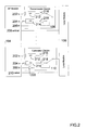
- FIG. 2 is a block diagram illustrating the detail of the transmission devices and their interconnections with a beamforming module and a loop module in accordance with an embodiment of the present invention.
- FIG. 3 is a block diagram illustrating the detail of the loop module and its interconnections with a beamforming module and two or more transmission devices in accordance with an embodiment of the present invention.
- FIG. 4 is a flowchart illustrating a method of calibrating signal processing paths in accordance with an embodiment of the present invention.
- FIG. 5 is a flowchart illustrating a method of calibrating signal processing paths in accordance with an embodiment of the present invention.
- FIG. 6 is a flowchart illustrating a method of obtaining of calibration data from each of two or more transmission devices in accordance with an embodiment of the present invention.
- FIG. 7 is a representative beamforming module 104 for calibrating multiple signal processing networks as shown in the system of FIG. 1 .
- FIG. 1 illustrates an exemplary system for carrying out an embodiment of the present invention.
- the system includes an interface (IF) module 102 , a beamforming (BF) module 104 , two or more transmission devices 108 , a loop module 106 , and two or more antennas 120 .
- IF interface
- BF beamforming
- the IF module 102 is used to interconnect the system with one or more modems 112 .
- Each type of modem will require a unique IF module 102 that is specifically designed to handle the unique interface and signaling requirements.
- the modems 112 are able to control the signal processing paths of the transmission devices 108 .
- the signal processing paths include both the Tx power output and Rx gain of the transmission devices 108 . Because the transmission devices 108 are used to carry signals from all the modems 112 simultaneously, control of the Tx power output and Rx gain cannot be accomplished by adjusting each transmission device output power and gain control.
- each of the transmission devices 108 is set to maximum Tx power and maximum Rx gain, and beamforming weights are applied to the system to obtain precise Tx power output control and Rx gain control for each transmission device 108 .
- Ideal beamforming weights are transmitted from the modems 112 to the IF module 102 .
- the IF module 102 is used to up-convert and down-convert signals from the modems 112 into a 30 MHz bandwidth that is used by the system and then the signals, including the ideal beamforming weights, are transmitted to the BF module 104 .
- the BF module 104 is used to perform the main beamforming function including the calibration of the transmission devices 108 .
- the BF module includes a beamforming unit 114 , a calibration unit 116 , and a central processing unit (CPU) 118 .
- CPU central processing unit
- the BF module 104 performs the multiply-accumulate functions necessary to control the Tx power output and Rx gain control of each of the transmission devices 108 .
- the BF module communicates with the modems 112 via the IF module 102 by means of 16-bit digital IF signal running at 60 MSamples/s.
- This digital signal is digitally down-converted to produce a baseband 32-bit i and q signal.
- This baseband 32-bit i and q signal is fed into the beamforming unit to produce a 32 bit i and q signal for each of the transmission devices 108 .
- These 32 bit i and q signals are sent out of the BF module 104 to the transmission devices 108 at a rate of 60 MSamples/s.
- the BF module 104 receives 32-bit i and q signals from each of the transmission devices 108 . These signals are fed into the beamforming unit 114 and will produce a 32 bit i and q signal for each of the modems 112 . The signals are then digitally up-converted producing a 16-bit IF signal at 60 MSamples/s that is sent to modems 112 via the IF module 102 .
- a calibration signal is created in the calibration unit 116 .
- the calibration signal is used to create an in-band signal used for calibration of delays through the transmission devices 108 .
- Received calibration data is obtained by passing a reference calibration signal through each of the transmission devices 108 and looped back to the calibration transmission device 110 by the loop module 106 and transferred back to the BF module 104 .
- the received calibration data is processed by the CPU 118 to ensure the received calibration data is of good quality and to create calibration weights before the received calibration data and the calibration weights are stored in the calibration unit.
- the beamforming unit 114 creates beamforming weights by combining the ideal beamforming weights with the calibration weights and the beamforming unit 114 applies the beamforming weights to the system.
- FIG. 1 depicts the system as having four transmission devices 108 though it should be readily understood that any number of two or more transmission devices 108 may be used.
- the transmission devices 108 provide the Time Division Duplex (TDD) channels used for beamforming and a calibration device 110 provides an additional channel used for calibration by sending and receiving a calibration signal that can be used to measure the differences between the transmission devices 108 .
- TDD Time Division Duplex
- the transmitter and receiver operate at the same frequency. Signals transmitted and received in a TDD system are not continuous in time. When a WiMAX signal is transmitted to an antenna, this time interval is referred to as the downlink subframe. When a WiMAX signal is received from the antenna, this time interval is referred to as the uplink subframe. Between transmit and receive intervals, gaps are defined by the WiMAX standard. The time gap occurring after the downlink subframe, but before the uplink subframe, is referred to as the TTG Gap. The time gap occurring after the uplink subframe, but before a subsequent downlink subframe, is referred to as the RTG Gap. The combination of the downlink subframe, the TTG Gap, the uplink subframe and the RTG Gap makes up one TDD period.
- the loop module 106 is used to control whether the signals received from the transmission devices 108 are looped to the calibration device 110 or transmitted to the antennas 120 .
- the BF module 104 uses an ant/cal signal 208 to control the loop module 106 to transmit or loop the transmission signals. Additionally, the BF module uses a calsel signal 210 to control the loop module 106 to determine which transmission device's signal is looped to the calibration device 110 .
- the loop module 106 must be carefully designed so as not to significantly impact differential phases of the multiple phase paths.
- FIG. 2 is a block diagram illustrating the transmission devices 108 and the calibration device 110 .
- the transmission devices 108 and calibration device 110 have a digital-to-analog (DAC) converter 212 to convert digital baseband i and q signals to radio frequency (RF) signals at a specified RF frequency.
- the RF signals are fed into an amplifier 216 and then transmitted to the loop module 106 .
- RF signals received from the loop module 106 are passed through an amplifier 218 and then an analog-to-digital (ADC) converter 214 to convert the RF signals to digital baseband i and q signals before being transmitted to the BF module 104 .
- ADC analog-to-digital
- Each transmission device 108 and the calibration device 110 has a t/r signal 206 used to control whether the Tx/Rx path is transmitted to/received from the loop module 106 . Additionally, the t/r signal 206 of the calibration device 110 is inverted by an inverter 220 so that the t/r signal 206 of the calibration device 110 will be opposite that of the transmission devices 108 , i.e., when the transmission devices 108 are set to transmit along the Tx path (t/r set to low), the calibration device 110 is set to receive from the Rx path (t/r set to high).
- the ant/cal signal 208 used to control the destination of the transmitted RF signals. If the ant/cal signal 208 is set to low, the RF signals of the transmission devices 108 are to be transmitted to the antennas 120 . If the ant/cal signal 208 is set to high, the RF signals of the transmission devices 108 are to be looped via the loop module 106 , with the RF signals from one of the transmission devices 108 to be received by the calibration device 110 . A calsel signal 210 is used by the loop module 106 to select the RF signals from one of the transmission devices 108 to be received by the calibration device 110 .
- FIG. 3 is a block diagram illustrating the interconnections between the BF module 104 , the transmission devices 108 , the calibration device 110 , the loop module 106 , and the antennas 120 .
- the loop module 106 has a switch 302 controlled by an ant/cal signal 208 for controlling the destination of the RF signals.
- the loop module 106 also has a switch 304 controlled by the calsel signal 210 that controls which transmission device's RF signals are looped back to the calibration device 110 .
- An attenuator 306 is disposed between the calibration device 306 and the switch 304 .
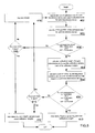
- FIG. 4 is a flowchart illustrating a method of calibrating signal processing paths according to one embodiment of the present invention.
- Step 402 a new set of calibration data is obtained for each of the transmission devices 108 and calibration tones are extracted for each of the transmission devices 108 .
- the obtaining of calibration data will be described in more detail with reference to FIG. 6 below.
- Calibration tones for a given transmission device are obtained by dividing the tones from a calibration signal for a references transmission device by the respective tones from a calibration signal for the given transmission device.
- the reference transmission device may be any one of the transmission devices 108 .
- Step 404 calibration weights are calculated for each of the transmission devices 108 and a calibration variance, ⁇ cal, is determined for the calibration weights across all the transmission devices 108 .
- the calibration weight for each of the transmission devices 108 is calculated by finding the average of the calibration tones for that transmission device.
- the calibration variance is the variation of the calibration weights across all the transmission devices 108 calculated in dB.
- Step 406 a phase variation, ⁇ p, and a magnitude variation, ⁇ m, are calculated for each of the transmission devices 108 with respect to the reference transmission device.
- the variation in phase over the frequency band must be first normalized. Normalization is obtained by finding the phase difference between each of the calibration tones and a reference calibration tone selected from among the calibration tones. For example, if there are six calibration tones, [A, B, C, D, E, F], and tone A is selected as the reference calibration tone, the phase difference between tones A and A, A and B, A and C, . . .
- phase difference between two calibration tones is simply the cross product of the two calibration tones. For example, if one calibration tone, A, is represented by the complex vector a, and another calibration tone, B, is represented by the complex vector b, the phase difference between the calibration tones is found by applying Equation (1).
- ⁇ p 180 ⁇ ⁇ ( max ⁇ ( PhaseDifference ) - min ⁇ ( PhaseDifference ) ) Equation ⁇ ⁇ ( 2 )
- the magnitude variation, ⁇ m is simply the variation of the absolute values of the calibration tones for that transmission device.
- Step 408 the calibration variance is compared to a calibration threshold, and, for each of the transmission devices 108 , the phase variation is compared to a phase variation threshold and the magnitude variation is compared to a magnitude variation threshold. If the calibration variance is below the calibration threshold, and, for each of the transmission devices 108 , the phase variation is below the phase variation threshold and the magnitude variation is below the magnitude variation threshold, then the method proceeds to Step 410 ; if not, the method proceeds to Step 414 .
- threshold values include a phase variation threshold of 5 degrees, a magnitude variation threshold of 0.5 dB, and a calibration variance threshold of 1 dB. Note that, however, the present invention is not limited to these values and other threshold values may be used based on the specific needs of a system.
- Step 410 any active alarms are cleared, a log is updated, and the calibration weights are stored in the calibration unit 116 .
- Step 414 it is checked if the process flow has been looped more than 3 times. If the process has not been looped more than 3 times, the method proceeds to Step 416 and error details are logged before proceeding back to Step 402 . If the process has been looped more than 3 times, the method proceeds to Step 412 , at which an alarm is activated, the error details are logged, and previously determined calibration weights stored in the calibration unit 116 are used by the system.
- FIG. 5 is a flowchart illustrating a method of calibrating signal processing paths according to a second embodiment of the present invention. More specifically, FIG. 5 illustrates an embodiment in which a signal-to-noise ratio (“SNR”) and a signal-to-DC ratio (“SDC”) are calculated and used to determine if the received calibration data is of good quality. For example, in order to achieve a +/ ⁇ 1 deg accuracy on the calibration results, the SNR should be at least 35 dB. The SDC value is used to confirm that the Quadrature Modulation Compensation (“QMC”) of the transmitters is functioning properly, and the SDC should be at least 25 dB.
- SNR signal-to-noise ratio
- SDC signal-to-DC ratio
- the method of calibration of FIG. 5 is similar to the method of calibration of FIG. 4 except the method of calibration of FIG. 5 includes additional steps of calculation of the SNR and the SDC of the received calibration data, and comparison of the SNR and SDC to predetermined thresholds to determine if the received calibration data is of good quality. Identical steps described above in reference to FIG. 4 will not be described below.
- Step 502 the SNR and the SDC is calculated for each of the transmission devices 108 .
- Equation (3) is used to calculate the SNR of the received calibration data, where I i and Q i are Fast Fourier Transform (“FFT”) results of the received calibration data, N FFT is the size of the FFT, N T is the number of tones used and T is the set of tones.
- FFT Fast Fourier Transform
- Equation (4) is used to calculate the SDC of the received calibration signal, where I i and Q i are FFT results of the received calibration data, N FFT is the size of the FFT, N T is the number of tones used and T is the set of tones.
- Step 504 for each transmission of the devices 108 , the SNR is compared to a SNR threshold, and the SDC is compared to a SDC threshold.
- the SNR threshold is set to 35 dB and the SDC threshold is set to 25 dB.
- 35 dB and 25 dB are used as the SNR threshold and the SDC threshold, respectively, the present invention is not limited to these values and other threshold values may be used to determine if the received calibration data is of good quality based on the specific needs of a system.
- Step 404 If, for each of the transmission devices 108 , the SNR is greater than the SNR threshold, and the SDC is greater than the SDC threshold, the received calibration data are judged to be of good quality and the method proceeds to Step 404 . However, if the received calibration is not judged to be of good quality, the method proceeds to Step 506 .
- Step 506 it is checked if the process flow has been looped more than 3 times. If the process has not been looped more than 3 times, the method proceeds to Step 416 and error details are logged before proceeding back to Step 402 . If the process has been looped more than 3 times, the method proceeds to Step 412 at which an alarm is activated, the error details are logged, and previously determined calibration weights are applied to the signal processing paths.
- FIG. 6 illustrates a flowchart describing a method of obtaining of calibration data from each of the transmission devices 108 .
- Beamforming requires the accurate control of the phase and amplitude of the signals to and from the antennas 120 .
- the transmission devices 108 are calibrated so that the differences in phase and amplitude between them can be compensated for.
- the calibration device 110 is used to send and receive a reference calibration signal that can be used to measure the differences between the active radios.
- the reference calibration signal is transmitted and received during the intervals when the system is neither transmitting nor receiving a WiMAX signal, i.e. during the TTG Gap or the RTG Gap. This ensures that the reference calibration signal does not interfere with the WiMAX signal and that the WiMAX signal does not interfere with the calibration signal. 300 samples of the reference calibration signal are transmitted, however calculations are only done on the middle 256 received samples. This is done to avoid any discontinuities in the received 256 samples.
- the reference calibration signal is simply a sum of tones that are chosen to cover the bandwidth of the system. Additionally, the tones are chosen to avoid 3 rd order inter-modulation products that would interfere with the reference calibration signal.
- Step 602 one of the transmission devices 108 is set as a specified transmission device.
- Step 604 the reference calibration signal is generated by the calibration unit 116 and loaded into the beamforming unit 114 .
- Step 606 the reference calibration signal is injected before the downlink subframe within the RTG gap duration so that useful WiMAX signals and the reference calibration signal are orthogonal to one another.
- Step 608 the reference calibration signal is sent through the Tx path of the calibration device 110 and looped back to the Rx path of the specified transmission device.
- the signal received by the specified transmission device is stored as calibration data in the calibration unit 116 for the specified transmission device.
- Step 610 the calibration signal is injected before the downlink subframe within the TTG gap duration.
- Step 612 the reference calibration signal is sent through the Tx path of the specified transmission device 108 and looped back to the Rx path of the calibration device 110 .
- the signal received by the calibration device 110 is stored as calibration data in the calibration unit 116 for the specified transmission device.
- Step 614 the method checks to see if the reference calibration signal has been sent through all the transmission devices 108 . If not, in Step 620 , a next transmission device is set as the specified transmission device and the method returns to Step 604 . If the reference calibration signal has been sent through all the transmission devices 108 , in Step 616 , the CPU 118 calculates calibration weights for each of the transmission devices 108 based on the respective stored calibration data in the calibration unit 116 .
- the beamforming unit 114 determines beamforming weights by multiplying ideal beamforming weights received from the modems 112 by the calculated calibration weights stored in the calibration unit 116 .
- the beamforming weights are applied to the Tx/Rx paths by the BF module 104 .
- the calibration process should be performed in a manner such that it is robust to single failures of any one Tx and/or Rx chain.
- the process should be able to identify which chain, if any, has failed. Additionally, a failed transmission device should not be used as a reference transmission device and the SNR and the SDC should not be checked for a failed transmission device.
- FIG. 7 is a representative BF module 104 for calibrating multiple signal processing paths as shown in the system of FIG. 1 .
- the BF module 104 includes a memory 710 , a processor 118 , user interface 702 , application programs 704 , communication interface 706 and bus 708 .
- the memory 710 can be computer-readable media used to store executable instructions, computer programs, algorithms or the like thereon.
- the memory 710 may include a read-only memory (ROM), random access memory (RAM), programmable read-only memory (PROM), erasable programmable read-only memory (EPROM), a smart card, a subscriber identity module (SIM), or any other medium from which a computing device can read executable instructions or a computer program.
- ROM read-only memory
- RAM random access memory
- PROM programmable read-only memory
- EPROM erasable programmable read-only memory
- SIM subscriber identity module
- computer programs is intended to encompass an executable program that exists permanently or temporarily on any computer-readable medium.
- the instructions, computer programs and algorithms stored in the memory 710 cause the BF module 104 to perform calibrating multiple signal processing paths as described in the system of FIG. 1 .
- the instructions, computer programs and algorithms stored in the memory 710 are executable by one or more processors 118 , which may
- the application programs 704 may also include, but are not limited to, an operating system or any special computer program that manages the relationship between application software and any suitable variety of hardware that helps to make-up a computer system or computing environment of the BF module 104 .
- General communication between the components in the BF module 104 is provided via the bus 708 .
- the user interface 702 allows for interaction between a user and the BF module 104 .
- the user interface 702 may include a keypad, a keyboard, microphone, and/or speakers.
- the communication interface 706 provides for two-way data communications from the BF module 104 .
- the communication interface 706 may be a digital subscriber line (DSL) card or modem, an integrated services digital network (ISDN) card, a cable modem, or a telephone modem to provide a data communication connection to a corresponding type of telephone line.
- communication interface 706 may be a local area network (LAN) card (e.g., for EthernetTM or an Asynchronous Transfer Model (ATM) network) to provide a data communication connection to a compatible LAN.
- LAN local area network
- the communication interface 706 may also include peripheral interface devices, such as a Universal Serial Bus (USB) interface, a Personal Computer Memory Card International Association (PCMCIA) interface, and the like.
- the communication interface 706 also allows the exchange of information across one or more wireless communication networks.
- Such networks may include cellular or short-range, such as IEEE 802.11 wireless local area networks (WLANS). And, the exchange of information may involve the transmission of radio frequency (FR) signals through an antenna (not shown).
- FR radio frequency
- the above disclosure defines the signal processing paths as being the Tx or Rx path of a transmission device. It is noted that the present invention is not limited to such disclosure and the above disclosure may be easily modified to work in a system containing signal processing paths consisting of an electrical/electronic/optical measurements system that allows an information/measurement signal with or without modulating a carrier to be processed through it.
Abstract
Description
Claims (26)
Priority Applications (2)
| Application Number | Priority Date | Filing Date | Title |
|---|---|---|---|
| US12/562,378 US8219035B2 (en) | 2009-09-18 | 2009-09-18 | Enhanced calibration for multiple signal processing paths in a wireless network |
| PCT/US2010/040573 WO2011034650A1 (en) | 2009-09-18 | 2010-06-30 | Enhanced calibration for multiple signal processing paths in a wireless network |
Applications Claiming Priority (1)
| Application Number | Priority Date | Filing Date | Title |
|---|---|---|---|
| US12/562,378 US8219035B2 (en) | 2009-09-18 | 2009-09-18 | Enhanced calibration for multiple signal processing paths in a wireless network |
Publications (2)
| Publication Number | Publication Date |
|---|---|
| US20110068971A1 US20110068971A1 (en) | 2011-03-24 |
| US8219035B2 true US8219035B2 (en) | 2012-07-10 |
Family
ID=43756181
Family Applications (1)
| Application Number | Title | Priority Date | Filing Date |
|---|---|---|---|
| US12/562,378 Active 2030-09-16 US8219035B2 (en) | 2009-09-18 | 2009-09-18 | Enhanced calibration for multiple signal processing paths in a wireless network |
Country Status (2)
| Country | Link |
|---|---|
| US (1) | US8219035B2 (en) |
| WO (1) | WO2011034650A1 (en) |
Cited By (1)
| Publication number | Priority date | Publication date | Assignee | Title |
|---|---|---|---|---|
| US11333735B2 (en) * | 2018-09-10 | 2022-05-17 | Kabushiki Kaisha Toshiba | Wireless communication device and wireless communication system |
Families Citing this family (8)
| Publication number | Priority date | Publication date | Assignee | Title |
|---|---|---|---|---|
| US8179314B2 (en) * | 2009-10-22 | 2012-05-15 | ReVerb Networks, Inc. | Enhanced calibration for multiple signal processing paths in a frequency division duplex system |
| US9008588B2 (en) | 2013-05-21 | 2015-04-14 | International Business Machines Corporation | System and method for the calibration and verification of wireless networks with control network |
| TW201448494A (en) * | 2013-06-05 | 2014-12-16 | Infolink System Integrations Corp | Radio frequency power compensation device |
| US20170338550A1 (en) * | 2014-10-28 | 2017-11-23 | New York University | System, method and computer-accessible medium for compliance assessment and active power management for safe use of radiowave emitting devices |
| NL2016671B1 (en) | 2016-04-25 | 2017-11-07 | Fugro N V | GNSS Message Authentication. |
| JP6977380B2 (en) * | 2017-08-02 | 2021-12-08 | 日本電気株式会社 | Active antenna system, communicator, active antenna system calibration method, and program |
| GB202011276D0 (en) * | 2020-07-21 | 2020-09-02 | Sofant Tech Ltd | Phased array antenna apparatus and method |
| CN115586501B (en) * | 2022-11-25 | 2023-03-10 | 四川九洲电器集团有限责任公司 | FPGA-based multichannel baseband data amplitude-phase compensation implementation method |
Citations (25)
| Publication number | Priority date | Publication date | Assignee | Title |
|---|---|---|---|---|
| US5155590A (en) | 1990-03-20 | 1992-10-13 | Scientific-Atlanta, Inc. | System for data channel level control |
| US5617101A (en) * | 1994-12-27 | 1997-04-01 | Motorola, Inc. | Satellite-based geolocation calibration system and method |
| US6124824A (en) | 1999-01-29 | 2000-09-26 | Cwill Telecommunications, Inc. | Adaptive antenna array system calibration |
| US6208287B1 (en) | 1998-03-16 | 2001-03-27 | Raytheoncompany | Phased array antenna calibration system and method |
| US6600445B2 (en) | 1999-08-10 | 2003-07-29 | China Academy Of Telecommunications Technology | Method and device for calibrating smart antenna array |
| US6690952B2 (en) | 1999-12-15 | 2004-02-10 | Nippon Telegraph & Telephone Corporation | Adaptive array antenna transceiver apparatus |
| US6747594B2 (en) | 2001-09-28 | 2004-06-08 | Arraycomm, Inc. | Calibration of differential frequency-dependent characteristics of a radio communications system |
| US20040120411A1 (en) | 2002-10-25 | 2004-06-24 | Walton Jay Rodney | Closed-loop rate control for a multi-channel communication system |
| US6765529B2 (en) | 2000-07-14 | 2004-07-20 | Sanyo Electric Co., Ltd. | Calibration device, adaptive array device, calibration method, program recording medium and program |
| US20040266483A1 (en) | 2001-10-05 | 2004-12-30 | Seung-Won Choi | Calibration apparatus for smart antenna and method thereof |
| EP1513271A2 (en) | 1998-05-01 | 2005-03-09 | ArrayComm, Inc. | Method and apparatus for determining spatial signatures for calibrating a communication station having an antenna array |
| US20060019712A1 (en) | 2001-11-14 | 2006-01-26 | Seung-Won Choi | Calibration apparatus for smart antenna and method thereof |
| US7003310B1 (en) | 2001-09-28 | 2006-02-21 | Arraycomm Llc. | Coupled uplink/downlink power control and spatial processing with adaptive antenna arrays |
| US7043199B2 (en) | 2001-06-06 | 2006-05-09 | Hughes Network Systems Llc | Uplink power control system for satellite communication system employing on-board satellite processing and fade estimation |
| US7098847B2 (en) | 2002-09-13 | 2006-08-29 | Da Tang Mobile Communications Equipment Co., Ltd. | Method for calibrating smart antenna array in real time |
| US20060232332A1 (en) * | 2005-04-13 | 2006-10-19 | Braithwaite Richard N | Adaptive predistortion linearized amplifier system employing selective sampling |
| US20070109995A1 (en) | 1998-10-30 | 2007-05-17 | Broadcom Corporation | Compensating for noise in a wireless communication system |
| US20070249404A1 (en) | 2006-04-04 | 2007-10-25 | Tenxc Wireless Inc. | Method and apparatus for adaptive beamforming in an antenna array system for wireless communications |
| US20070298733A1 (en) | 2006-06-23 | 2007-12-27 | Sierra Monolithics, Inc., A California Corporation | Apparatus and method for calibration of gain and/or phase imbalance and/or DC offset in a communication system |
| WO2008009421A2 (en) | 2006-07-17 | 2008-01-24 | Ubidyne Inc. | Antenna array system |
| US7359734B2 (en) | 2002-09-24 | 2008-04-15 | Nokia Corporation | Compensating for radiation pattern in radio system, and radio system |
| US20080090531A1 (en) | 2006-10-16 | 2008-04-17 | Jungerman Roger L | Vector modulator calibration system |
| US20100013709A1 (en) | 2008-06-20 | 2010-01-21 | Johannes Schlee | Antenna Array and A Method For Calibration Thereof |
| US20110022904A1 (en) * | 2009-07-21 | 2011-01-27 | Broadcom Corporation | Modem-assisted bit error concealment for audio communications systems |
| US20110095944A1 (en) * | 2009-10-22 | 2011-04-28 | Richard Glenn Kusyk | Enhanced calibration for multiple signal processing paths in a frequency division duplex system |
Family Cites Families (1)
| Publication number | Priority date | Publication date | Assignee | Title |
|---|---|---|---|---|
| EP1610321B1 (en) * | 2000-10-27 | 2006-12-27 | Matsushita Electric Industries Co., Ltd. | Motor and disk drive apparatus using said motor |
-
2009
- 2009-09-18 US US12/562,378 patent/US8219035B2/en active Active
-
2010
- 2010-06-30 WO PCT/US2010/040573 patent/WO2011034650A1/en active Application Filing
Patent Citations (26)
| Publication number | Priority date | Publication date | Assignee | Title |
|---|---|---|---|---|
| US5155590A (en) | 1990-03-20 | 1992-10-13 | Scientific-Atlanta, Inc. | System for data channel level control |
| US5617101A (en) * | 1994-12-27 | 1997-04-01 | Motorola, Inc. | Satellite-based geolocation calibration system and method |
| US6208287B1 (en) | 1998-03-16 | 2001-03-27 | Raytheoncompany | Phased array antenna calibration system and method |
| EP1513271A2 (en) | 1998-05-01 | 2005-03-09 | ArrayComm, Inc. | Method and apparatus for determining spatial signatures for calibrating a communication station having an antenna array |
| US20070109995A1 (en) | 1998-10-30 | 2007-05-17 | Broadcom Corporation | Compensating for noise in a wireless communication system |
| US6124824A (en) | 1999-01-29 | 2000-09-26 | Cwill Telecommunications, Inc. | Adaptive antenna array system calibration |
| US6195045B1 (en) | 1999-01-29 | 2001-02-27 | Cwill Telecommunication, Inc. | Adaptive antenna array system calibration |
| US6600445B2 (en) | 1999-08-10 | 2003-07-29 | China Academy Of Telecommunications Technology | Method and device for calibrating smart antenna array |
| US6690952B2 (en) | 1999-12-15 | 2004-02-10 | Nippon Telegraph & Telephone Corporation | Adaptive array antenna transceiver apparatus |
| US6765529B2 (en) | 2000-07-14 | 2004-07-20 | Sanyo Electric Co., Ltd. | Calibration device, adaptive array device, calibration method, program recording medium and program |
| US7043199B2 (en) | 2001-06-06 | 2006-05-09 | Hughes Network Systems Llc | Uplink power control system for satellite communication system employing on-board satellite processing and fade estimation |
| US6747594B2 (en) | 2001-09-28 | 2004-06-08 | Arraycomm, Inc. | Calibration of differential frequency-dependent characteristics of a radio communications system |
| US7003310B1 (en) | 2001-09-28 | 2006-02-21 | Arraycomm Llc. | Coupled uplink/downlink power control and spatial processing with adaptive antenna arrays |
| US20040266483A1 (en) | 2001-10-05 | 2004-12-30 | Seung-Won Choi | Calibration apparatus for smart antenna and method thereof |
| US20060019712A1 (en) | 2001-11-14 | 2006-01-26 | Seung-Won Choi | Calibration apparatus for smart antenna and method thereof |
| US7098847B2 (en) | 2002-09-13 | 2006-08-29 | Da Tang Mobile Communications Equipment Co., Ltd. | Method for calibrating smart antenna array in real time |
| US7359734B2 (en) | 2002-09-24 | 2008-04-15 | Nokia Corporation | Compensating for radiation pattern in radio system, and radio system |
| US20040120411A1 (en) | 2002-10-25 | 2004-06-24 | Walton Jay Rodney | Closed-loop rate control for a multi-channel communication system |
| US20060232332A1 (en) * | 2005-04-13 | 2006-10-19 | Braithwaite Richard N | Adaptive predistortion linearized amplifier system employing selective sampling |
| US20070249404A1 (en) | 2006-04-04 | 2007-10-25 | Tenxc Wireless Inc. | Method and apparatus for adaptive beamforming in an antenna array system for wireless communications |
| US20070298733A1 (en) | 2006-06-23 | 2007-12-27 | Sierra Monolithics, Inc., A California Corporation | Apparatus and method for calibration of gain and/or phase imbalance and/or DC offset in a communication system |
| WO2008009421A2 (en) | 2006-07-17 | 2008-01-24 | Ubidyne Inc. | Antenna array system |
| US20080090531A1 (en) | 2006-10-16 | 2008-04-17 | Jungerman Roger L | Vector modulator calibration system |
| US20100013709A1 (en) | 2008-06-20 | 2010-01-21 | Johannes Schlee | Antenna Array and A Method For Calibration Thereof |
| US20110022904A1 (en) * | 2009-07-21 | 2011-01-27 | Broadcom Corporation | Modem-assisted bit error concealment for audio communications systems |
| US20110095944A1 (en) * | 2009-10-22 | 2011-04-28 | Richard Glenn Kusyk | Enhanced calibration for multiple signal processing paths in a frequency division duplex system |
Non-Patent Citations (3)
| Title |
|---|
| International Search Report dated Sep. 21, 2010 in International (PCT) Application No. PCT/US2010/40573. |
| International Search Report issued Nov. 15, 2010 in International (PCT) Application No. PCT/US2010/049083. |
| U.S. Office Action mailed Aug. 5, 2011 for U.S. Appl. No. 12/603,907, filed Oct. 22, 2009. |
Cited By (1)
| Publication number | Priority date | Publication date | Assignee | Title |
|---|---|---|---|---|
| US11333735B2 (en) * | 2018-09-10 | 2022-05-17 | Kabushiki Kaisha Toshiba | Wireless communication device and wireless communication system |
Also Published As
| Publication number | Publication date |
|---|---|
| WO2011034650A1 (en) | 2011-03-24 |
| US20110068971A1 (en) | 2011-03-24 |
Similar Documents
| Publication | Publication Date | Title |
|---|---|---|
| US8219035B2 (en) | Enhanced calibration for multiple signal processing paths in a wireless network | |
| EP1670094B1 (en) | Smart antenna communication system for signal calibration | |
| KR100656979B1 (en) | A method for calibrating smart antenna array systems in real time | |
| US6400318B1 (en) | Adaptive array antenna | |
| US8432997B2 (en) | Method and system of beamforming a broadband signal through a multiport network | |
| CN100393139C (en) | Apparatus and method for beamforming in changing-interference environment | |
| EP1438768B1 (en) | Frequency dependent calibration of a wideband radio system using narrowband channels | |
| US8208963B2 (en) | Communication method and system | |
| US8428529B2 (en) | Method and system for uplink beamforming calibration in a multi-antenna wireless communication system | |
| US6747594B2 (en) | Calibration of differential frequency-dependent characteristics of a radio communications system | |
| FI111111B (en) | A method for controlling the power of a random access packet transmitted by a mobile station in a radio communication system and a system using the method | |
| US9300382B2 (en) | Wireless signal processor and wireless apparatus | |
| JP3920350B2 (en) | Self-calibration apparatus and method for communication devices | |
| US20150288462A1 (en) | Method for Channel Calibration | |
| US10541760B2 (en) | Radio communication apparatus and antenna calibration method | |
| US8179314B2 (en) | Enhanced calibration for multiple signal processing paths in a frequency division duplex system | |
| JP2002530998A (en) | Method and apparatus for calibrating a wireless communication station having an array antenna | |
| US20210021297A1 (en) | Angle of propagation estimation in a multipath communication system | |
| JP3589605B2 (en) | Adaptive array antenna transceiver | |
| US20010012765A1 (en) | Method and arrangement for controlling transmitted power in a telecommunication system | |
| US20180167127A1 (en) | Communication control device and phase adjusting method | |
| EP2485327A2 (en) | Method and system of beamforming a broadband signal through a multiport network | |
| US20080112493A1 (en) | Method and System for Recursively Detecting MIMO Signals |
Legal Events
| Date | Code | Title | Description |
|---|---|---|---|
| AS | Assignment |
Owner name: REVERB NETWORKS, VIRGINIA Free format text: ASSIGNMENT OF ASSIGNORS INTEREST;ASSIGNOR:KUSYK, RICHARD GLENN;REEL/FRAME:023256/0768 Effective date: 20090908 |
|
| STCF | Information on status: patent grant |
Free format text: PATENTED CASE |
|
| CC | Certificate of correction | ||
| AS | Assignment |
Owner name: VIAVI SOLUTIONS INC., CALIFORNIA Free format text: ASSIGNMENT OF ASSIGNORS INTEREST;ASSIGNOR:REVERB NETWORKS, INC.;REEL/FRAME:037255/0412 Effective date: 20151206 |
|
| FPAY | Fee payment |
Year of fee payment: 4 |
|
| FEPP | Fee payment procedure |
Free format text: PAYOR NUMBER ASSIGNED (ORIGINAL EVENT CODE: ASPN); ENTITY STATUS OF PATENT OWNER: LARGE ENTITY |
|
| FEPP | Fee payment procedure |
Free format text: PAT HOLDER NO LONGER CLAIMS SMALL ENTITY STATUS, ENTITY STATUS SET TO UNDISCOUNTED (ORIGINAL EVENT CODE: STOL); ENTITY STATUS OF PATENT OWNER: LARGE ENTITY |
|
| MAFP | Maintenance fee payment |
Free format text: PAYMENT OF MAINTENANCE FEE, 8TH YEAR, LARGE ENTITY (ORIGINAL EVENT CODE: M1552); ENTITY STATUS OF PATENT OWNER: LARGE ENTITY Year of fee payment: 8 |
|
| AS | Assignment |
Owner name: WELLS FARGO BANK, NATIONAL ASSOCIATION, AS ADMINISTRATIVE AGENT, COLORADO Free format text: SECURITY INTEREST;ASSIGNORS:VIAVI SOLUTIONS INC.;3Z TELECOM, INC.;ACTERNA LLC;AND OTHERS;REEL/FRAME:052729/0321 Effective date: 20200519 |
|
| AS | Assignment |
Owner name: RPC PHOTONICS, INC., NEW YORK Free format text: TERMINATIONS OF SECURITY INTEREST AT REEL 052729, FRAME 0321;ASSIGNOR:WELLS FARGO BANK, NATIONAL ASSOCIATION, AS ADMINISTRATIVE AGENT;REEL/FRAME:058666/0639 Effective date: 20211229 Owner name: VIAVI SOLUTIONS INC., CALIFORNIA Free format text: TERMINATIONS OF SECURITY INTEREST AT REEL 052729, FRAME 0321;ASSIGNOR:WELLS FARGO BANK, NATIONAL ASSOCIATION, AS ADMINISTRATIVE AGENT;REEL/FRAME:058666/0639 Effective date: 20211229 |
|
| MAFP | Maintenance fee payment |
Free format text: PAYMENT OF MAINTENANCE FEE, 12TH YEAR, LARGE ENTITY (ORIGINAL EVENT CODE: M1553); ENTITY STATUS OF PATENT OWNER: LARGE ENTITY Year of fee payment: 12 |