US8224122B2 - Dynamic viewing of wide angle images - Google Patents
Dynamic viewing of wide angle images Download PDFInfo
- Publication number
- US8224122B2 US8224122B2 US11/738,903 US73890307A US8224122B2 US 8224122 B2 US8224122 B2 US 8224122B2 US 73890307 A US73890307 A US 73890307A US 8224122 B2 US8224122 B2 US 8224122B2
- Authority
- US
- United States
- Prior art keywords
- view
- screen
- projection
- wide angle
- perspective
- Prior art date
- Legal status (The legal status is an assumption and is not a legal conclusion. Google has not performed a legal analysis and makes no representation as to the accuracy of the status listed.)
- Active, expires
Links
- 238000000034 method Methods 0.000 claims abstract description 74
- 230000007704 transition Effects 0.000 claims abstract description 14
- 230000008569 process Effects 0.000 claims description 44
- 230000009471 action Effects 0.000 claims description 32
- 238000009877 rendering Methods 0.000 claims description 28
- 238000013507 mapping Methods 0.000 claims description 17
- 238000002156 mixing Methods 0.000 claims description 15
- 238000005452 bending Methods 0.000 claims description 11
- WPNJAUFVNXKLIM-UHFFFAOYSA-N Moxonidine Chemical compound COC1=NC(C)=NC(Cl)=C1NC1=NCCN1 WPNJAUFVNXKLIM-UHFFFAOYSA-N 0.000 claims description 5
- 239000000203 mixture Substances 0.000 claims description 2
- 238000004891 communication Methods 0.000 description 7
- 238000004091 panning Methods 0.000 description 7
- 238000013459 approach Methods 0.000 description 6
- 230000008901 benefit Effects 0.000 description 5
- 238000006243 chemical reaction Methods 0.000 description 5
- 229920000535 Tan II Polymers 0.000 description 4
- 238000010586 diagram Methods 0.000 description 4
- 230000009466 transformation Effects 0.000 description 4
- 238000005516 engineering process Methods 0.000 description 3
- 230000006870 function Effects 0.000 description 3
- 238000012545 processing Methods 0.000 description 3
- 230000003287 optical effect Effects 0.000 description 2
- 238000012800 visualization Methods 0.000 description 2
- 238000003491 array Methods 0.000 description 1
- 230000008859 change Effects 0.000 description 1
- 230000000694 effects Effects 0.000 description 1
- 230000001747 exhibiting effect Effects 0.000 description 1
- 239000012634 fragment Substances 0.000 description 1
- 230000005055 memory storage Effects 0.000 description 1
- 230000003340 mental effect Effects 0.000 description 1
- 239000003973 paint Substances 0.000 description 1
- 238000000844 transformation Methods 0.000 description 1
- 230000007723 transport mechanism Effects 0.000 description 1
Images


Classifications
-
- G06T3/047—
Definitions
- An image can be thought of as a two dimensional set of rays or directions passing through a small pinhole representing the viewpoint of the image. These rays are mapped to a 2D surface for display.
- the mapping for standard images is created through a “perspective” transformation involving projecting the rays onto a planar surface. This is called a perspective projection and has the advantage of keeping all straight lines straight.
- perspective projections begin to create large distortions as the field of view passes 90 degrees and as it approaches 180 degrees the distortion becomes infinitely large.
- other projections have been developed, such as projections onto cylindrical or spherical surfaces (i.e., projecting onto a curved surface). These projections are “unwrapped” to the plane of a screen for display. This unwrapping allows very wide angle images to be displayed but at the cost of a certain flattening of the result and making straight lines in the world appear curved.
- the present dynamic wide angle image viewing technique provides a way to view a wide-angle image while zooming between a wide angle view and a narrower angle view that employs both perspective and non-perspective projection models.
- this involves first establishing the field of view and viewing direction for the view (i.e., frame) of the wide angle image that is to be displayed. The view is then rendered and displayed, such that its projection transitions between a perspective projection associated with narrower angle views and a non-perspective projection (e.g., cylindrical, spherical or some other parameterization) associated with wider-angle views.
- a non-perspective projection e.g., cylindrical, spherical or some other parameterization
- the transition between the projections is abrupt and occurs at a prescribed zoom level.
- a pair of screen coordinates is first established for each pixel or selected pixels representing vertices of a mesh on a display screen.
- the field of view and viewing direction that are to be used to generate the view of the wide angle image are established.
- a ray defined by two angles is computed. This ray represents the direction from the viewer through the pair of screen coordinates under consideration.
- the view represents a projection that is either perspective, a fully curved non-perspective or lies between a perspective projection and the non-perspective projection.
- this is generated by warping the perspective projection toward the non-perspective projection by an amount that is proportional to the established field of view, with the amount of warping being greater for wider fields of view up to the limit of the non-perspective projection itself.
- the view of the wide angle image is rendered based on the computed rays. The rendered view is then displayed on the display screen.
- the field of view and a central viewing direction are established, which are to be used to generate the view of the wide angle image.
- a pair of screen coordinates is then established for each of a set of viewing directions of interest within the established field of view and surrounding the central viewing direction, which is associated with a perspective projection of a view being rendered.
- a pair of screen coordinates is also established for each of the set of viewing directions of interest associated with a non-perspective projection of the view being rendered.
- the field of view of the frame being rendered based on the zoom level is less than or equal to a prescribed minimum field of view value, more than or equal to a prescribed maximum field of view value, or in between the prescribed values. If the field of view is found to be less than or equal to the prescribed minimum field of view value, the screen coordinates defined by the perspective projection model for the viewing direction under consideration are identified. If, on the other hand, it is determined that the field of view of the frame being rendered based on the zoom level is more than or equal to the prescribed maximum field of view value, the screen coordinates defined by the non-perspective projection model for viewing direction under consideration are identified.
- a blending approach is taken.
- the screen coordinates defined by both the perspective and non-perspective models for the viewing direction under consideration are identified.
- An interpolated pair of screen coordinates is then computed based on a blending of the identified screen coordinates associated with the perspective and non-perspective projection models.
- the view that is to be displayed is rendered using each pair of the identified screen coordinates, or each pair of the blended screen coordinates, as the case may be. The view is then displayed on the display screen.
- FIG. 1 is a diagram depicting a general purpose computing device constituting an exemplary system for implementing the present invention.
- FIG. 2 is a flow diagram generally outlining a technique embodying the present invention for dynamically viewing a wide angle image by providing views transitioning between a perspective projection and a non-perspective projection while zooming between wide angle and narrow angle views of the image.
- FIG. 3 is a flow diagram generally outlining one embodiment of a process for dynamically viewing a wide angle image which smoothly transitions between the perspective projection and a non-perspective projection.
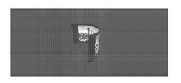
- FIG. 4 is an image of a world space visualization of a perspective projection of a wide angle image.
- FIG. 5 is an image of a screen display of a perspective projection of a wide angle image.
- FIG. 6 is an image of a world space visualization of a non-perspective, cylindrical projection of a wide angle image.
- FIG. 7 is an image of a screen display of a non-perspective, cylindrical projection of a wide angle image.
- FIG. 8 is a graph illustrating how a surface can be warped from a flat/perspective to a cylindrical/perspective, with some intermediate projections mixing the perspective and cylindrical perspectives also shown.
- FIG. 9 is a graph depicting an alternative way of viewing the surfaces of FIG. 8 as cylinders of increasing radii with the viewpoint kept at a unit distance away from the cylinder wall.
- FIG. 10 is a graph depicting a close-up portion of the graph of FIG. 9 , with additional partial cylinders shown.
- FIGS. 11A-B are a continuing flow diagram generally outlining one embodiment of a process for dynamically viewing a wide angle image which transitions between the perspective projection and a non-perspective projection using a blending approach.
- FIG. 12 is a pseudo code listing for computing interpolated x and y values in accordance with one embodiment of a process for dynamically viewing a wide angle image which transitions between the perspective projection and a non-perspective projection using a blending approach.
- the present dynamic wide-angle image viewing technique is operational with numerous general purpose or special purpose computing system environments or configurations.
- Examples of well known computing systems, environments, and/or configurations that may be suitable include, but are not limited to, personal computers, server computers, hand-held or laptop devices, multiprocessor systems, microprocessor-based systems, set top boxes, programmable consumer electronics, network PCs, minicomputers, mainframe computers, distributed computing environments that include any of the above systems or devices, and the like.
- FIG. 1 illustrates an example of a suitable computing system environment.
- the computing system environment is only one example of a suitable computing environment and is not intended to suggest any limitation as to the scope of use or functionality of the present dynamic wide-angle image viewing technique. Neither should the computing environment be interpreted as having any dependency or requirement relating to any one or combination of components illustrated in the exemplary operating environment.
- an exemplary system for implementing the present dynamic wide-angle image viewing technique includes a computing device, such as computing device 100 . In its most basic configuration, computing device 100 typically includes at least one processing unit 102 and memory 104 .
- memory 104 may be volatile (such as RAM), non-volatile (such as ROM, flash memory, etc.) or some combination of the two. This most basic configuration is illustrated in FIG. 1 by dashed line 106 .
- device 100 may also have additional features/functionality.
- device 100 may also include additional storage (removable and/or non-removable) including, but not limited to, magnetic or optical disks or tape. Such additional storage is illustrated in FIG. 1 by removable storage 108 and non-removable storage 110 .
- Computer storage media includes volatile and nonvolatile, removable and non-removable media implemented in any method or technology for storage of information such as computer readable instructions, data structures, program modules or other data.
- Computer storage media includes, but is not limited to, RAM, ROM, EEPROM, flash memory or other memory technology, CD-ROM, digital versatile disks (DVD) or other optical storage, magnetic cassettes, magnetic tape, magnetic disk storage or other magnetic storage devices, or any other medium which can be used to store the desired information and which can accessed by device 100 . Any such computer storage media may be part of device 100 .
- Device 100 may also contain communications connection(s) 112 that allow the device to communicate with other devices.
- Communications connection(s) 112 is an example of communication media.
- Communication media typically embodies computer readable instructions, data structures, program modules or other data in a modulated data signal such as a carrier wave or other transport mechanism and includes any information delivery media.
- modulated data signal means a signal that has one or more of its characteristics set or changed in such a manner as to encode information in the signal.
- communication media includes wired media such as a wired network or direct-wired connection, and wireless media such as acoustic, RF, infrared and other wireless media.
- the term computer readable media as used herein includes both storage media and communication media.
- Device 100 may also have input device(s) 114 such as keyboard, mouse, pen, voice input device, touch input device, etc.
- Output device(s) 116 such as a display, speakers, printer, etc. may also be included. All these devices are well know in the art and need not be discussed at length here.
- device 100 can include a camera 118 (such as a digital/electronic still or video camera, or film/photographic scanner), which is capable of capturing a sequence of images, as an input device. Further, multiple cameras 118 could be included as input devices. The images from the one or more cameras are input into the device 100 via an appropriate interface (not shown). However, it is noted that image data can also be input into the device 100 from any computer-readable media as well, without requiring the use of a camera.
- a camera 118 such as a digital/electronic still or video camera, or film/photographic scanner
- the present dynamic wide-angle image viewing technique may be described in the general context of computer-executable instructions, such as program modules, being executed by a computing device.
- program modules include routines, programs, objects, components, data structures, etc. that perform particular tasks or implement particular abstract data types.
- the present dynamic wide-angle image viewing technique may also be practiced in distributed computing environments where tasks are performed by remote processing devices that are linked through a communications network.
- program modules may be located in both local and remote computer storage media including memory storage devices.
- Exploring wide angle, high resolution imagery on a computer involves freely moving between an overall view of the scene and a portion of the wide angle field of view. Panning (i.e., moving left-right, up-down) and zooming (i.e., changing the field of view) a virtual camera on the overall image allows a user to explore both the breadth and depth of the scene depicted.
- This exploration can involve viewing environments such as panoramic imagery, lat/long datasets such as the globe, or virtual environments such as 3D games.
- the user employs a panning operator and a zooming operator to pan and zoom through the wide angle image.
- Examples of how these operators are implemented include panning by moving a screen cursor left, right, up, and down with the left mouse button pushed. Zooming could be achieved by scrolling the mouse wheel if available, or moving the cursor up and down with the right mouse button pressed.
- Other user-interface methods can also be used, such as including scroll bars or other affordances.
- the underlying image is stored in some parameterization that maps ray directions to pixel locations.
- a ray may represent a virtual ray that intersects a 3D virtual world at runtime. This mapping is thus typically either:
- mappings are also possible including fisheye and other parameterizations.
- the present dynamic wide angle image viewing technique provides a way to view a wide-angle image while zooming between a wide angle view and a narrower angle view.
- this generally involves for each view (i.e., frame) of the wide angle image to be presented, first establishing the field of view desired for the frame ( 200 ). Then, the frame is rendered and displayed based on the established field of view such that the projection transitions between a perspective projection associated with narrower angle views and a non-perspective projection (e.g., cylindrical, spherical or some other parameterization) associated with wider-angle views ( 202 ).
- This is very effective for panning and zooming over large images and provides the best of both viewing paradigms in a unified framework.
- the idea is to dynamically change the viewing projection on the fly as a viewer zooms in and out of an image.
- a decision must be made with each frame as to which “virtual camera model” to use to map the pixels in the underlying representation to the computer screen to provide the best view.
- virtual camera model Just as with the image's underlying representation, a perspective, cylindrical, spherical, or other camera model are possibilities. The decision is based on the zoom level associated with the frame.
- the transition between the projections is abrupt and occurs at a prescribed zoom level.
- the image is viewed in such a way as to utilize perspective as well as cylindrical and spherical projections (or other non-perspective parameterizations) in a seamless manner adapting to the momentary field of view being requested.
- the view smoothly transitions between different projections.
- a (left-handed) world coordinate system is established with the viewer sitting at the origin (0,0,0), and light is coming in from all directions.
- the directions can be parameterized by two angles ( ⁇ , ⁇ ), ⁇ can be thought of as the longitude on the surrounding sphere and ⁇ as the latitude.
- the x axis is to the right, the y axis is up.
- the viewing projection i.e., how is the world is viewed, e.g. perspectively
- the texture projection i.e., how is the image is stored in the texture, e.g. perspective, cylindrical, spherical
- a ray ( ⁇ , ⁇ ) is computed for each pixel (or vertex location as will be described shortly). This computation will also be described in more detail later.
- the ⁇ and ⁇ correspond to world space angles (i.e., a spherical projection), however, this may not be the projection in which the image data (i.e., texture) has been stored. Accordingly, a straight forward conversion is made between the projection associated with the ⁇ and ⁇ values and the texture coordinates of the projection associated with the image data. These conversions are well known and so will not be described in any detail in the present description. Once the texture coordinates are known, the texture corresponding to these coordinates is obtained from the stored image data and used to render the pixel under consideration.
- the present dynamic wide angle image viewing technique is accomplished as follows. Referring to FIG. 3 , a pair of screen coordinates is first established for each pixel or vertex location of the display screen ( 300 ). In addition, the field of view and viewing direction that are used to generate the view of the wide angle image that is to be displayed, are established ( 302 ). For example, when a user is zooming from a wide angle view to a narrower angle view, or vice versa, views of the image exhibiting different fields of view related to the zoom level will be rendered and displayed at some prescribed rate (such as the refresh rate of the display screen). Thus, the field of view associated with a particular view would be established by the current zoom level existing at the time the view is rendered. The user might also be panning across the wide angle image. Thus, the viewing direction is established to identify the region of the image that is to be rendered.
- the technique continues with the selection of a previously unselected pair of screen coordinates ( 304 ).
- the aforementioned ray which represents the direction from the viewer through the selected pair of screen coordinates, is computed next ( 306 ).
- the ray is determined by a projection that is between a perspective projection and the non-perspective projection. This can be generated by warping the perspective projection toward the non-perspective projection by an amount that is proportional to the established field of view, with the amount of warping being greater for wider fields of view up to the limit of the non-perspective projection itself.
- the next action in this embodiment of the present dynamic wide angle image viewing technique is to determine if all the pairs of screen coordinates have been selected and processed ( 308 ). If not, then actions ( 304 ) through ( 308 ) are repeated until all the coordinate pairs have been processed.
- the view of the wide angle image is rendered next based on the computed rays ( 310 ).
- the projection in which the image data has been stored may or may not correspond to the spherical projection coordinates associated with the ray. If it does correspond, then rendering involves identifying the texture coordinates in a stored mapping of the wide angle image that correspond to the computed rays, and then obtaining the texture data corresponding to the identified texture coordinates from the mapping. The view is rendered using the obtained texture data.
- the rendering involves a preliminary action of converting the direction represented by each computed ray to the projection employed by the stored mapping. Once this conversion is made, the rendering proceeds as described above.
- the rendering involves generating the texture data corresponding to the identified texture coordinates. In this latter case, the view is rendered using the generated texture data. Finally, the rendered view is displayed on the display screen ( 312 ).
- the screen is tessellated into a fine grid of vertices.
- the texture coordinates are computed for each vertex in the manner described previously for pixels, and then the vertex array is rendered to the screen.
- an index buffer was used to define an array of quads over the vertex grid.
- a mental image when thinking about projections is the following. Take a display screen, place it in the world coordinate system, and paint it by intersecting the light rays with it. In the world coordinate system, the screen can be called the “projective surface” or just surface for short. In a final step, if this surface is curved, it is flattened out to the computer screen for display purposes.
- the projective surface is smoothly warped from a flat surface when the field of view is small (e.g., below about 60 degrees) to one that is fully curved (into a cylinder or sphere) when the field of view exceeds some threshold (e.g., about 120 degrees).
- the surface is also scaled to maintain a smoothly varying size at the center of the screen during the warp. Given this idea of bending the surface, it is easy to come up with a projection that is in-between a perspective and a non-perspective projection by just bending the surface part of the way. For example, in the case of a cylindrical projection, the surface is bent, as shown in FIG. 8 , from a flat/perspective 800 to a cylindrical surface 802 .
- the light rays meet in the center of projection represented by the small cross 804 .
- Some intermediate projections 806 mixing perspective and cylindrical, are also shown. Alternatively this can be viewed as increasing the radius of the cylinder while always keeping the viewpoint a unit distance away from the cylinder wall, as shown in FIGS. 9 and 10 .
- FIGS. 9 and 10 show how enlarging and moving the circles has the effect of unbending the surface.
- the surfaces 806 in FIG. 8 are created by cutting out arcs of constant length from the circles in FIGS. 9 and 10 .
- Zooming is done simply by scaling x screen and y screen .
- the foregoing bending parameters (i.e., ⁇ and ⁇ ) used to compute the ⁇ and ⁇ angles, are set automatically based on the zoom level (i.e. the scaling of the projective surface).
- the parameters mid and scale in Eqs. (21) and (22) control where the sigmoid hits ⁇ max /2, and the steepness.
- the mid parameter can range between 50 and 130 degrees
- the scale parameter can range between 2 and 10.
- ⁇ and ⁇ were computed given an x and y screen coordinate pair.
- a ⁇ and ⁇ were computed.
- Another way of approaching the problem is to first establish a mesh of vertices defining a triangulation on the input parameterization, ⁇ and ⁇ . These vertices are then mapped to a virtual geometric object, for example a unit sphere if the input parameterization is spherical. This object is rotated to the current viewing direction. Each vertex is then be projected to one or more viewing parameterizations, for example, perspective planes, cylinders, or spheres using well known methods.
- the corresponding projected points are interpolated in screen space. This establishes the texture coordinates corresponding to each vertex of the mesh on the screen.
- the resulting triangles from the mesh are then rendered using standard graphics processing.
- the alternate technique involves first establishing the field of view and a central viewing direction that are to be used to generate the view of the wide angle image ( 1100 ).
- the central viewing direction is the direction from the viewpoint toward the center of the current region of the wide angle image that is to be rendered and displayed.
- a pair of screen coordinates is then established for each of a set of viewing directions of interest within the established field of view and surrounding the established central viewing direction, which is associated with a perspective projection of a view being rendered ( 1102 ).
- a pair of screen coordinates is established for each of a set of viewing directions of interest within the established field of view and surrounding the established central viewing direction, which is associated with a non-perspective projection of the view being rendered ( 1104 ).
- the viewing directions of interest could be associated with, for example each pixel or vertex location of the view that is to be rendered and displayed.
- a previously unselected viewing direction is selected from the set of viewing directions of interest ( 1106 ). It is then determined if the field of view of the frame being rendered based on the zoom level is less than or equal to a prescribed minimum field of view value (e.g., about 60 degrees), more than or equal to a prescribed maximum field of view value (e.g., about 120 degrees), or in between the prescribed values ( 1108 ). If the field of view is found to be less than the prescribed minimum field of view value, the screen coordinate values x and y defined by the perspective projection model for the selected ⁇ and ⁇ values are identified ( 1110 ).
- a prescribed minimum field of view value e.g., about 60 degrees
- a prescribed maximum field of view value e.g., about 120 degrees
- the x and y values defined by the non-perspective projection model for the selected ⁇ and ⁇ values are identified.
- a blending approach is taken. More particularly, the x and y values defined by both the perspective and non-perspective models for the selected ⁇ and ⁇ values are identified ( 1114 ). An interpolated pair of screen coordinates is then computed based on a blending of the identified screen coordinates associated with the perspective and non-perspective projection models ( 1116 ).
- this is accomplished using a blending factor, alpha.
- Alpha is computed as the difference between the maximum field of view value and the field of view associated with the current frame being rendered, divided by the difference between the maximum field of view value and the minimum field of view value.
- the interpolated x and y values for each pixel or vertex are then computed as a linear blend of the x and y values defined by the pre-computed perspective projection model, and the x and y values pre-computed by the non-perspective projection model for the selected ⁇ and ⁇ values and the field of view.
- the technique continues by determining if all the directions in the set of directions of interest have been selected and processed ( 1118 ). If not, actions ( 1106 ) through ( 1118 ) are repeated until all the directions have been considered. At that point, the view that is to be displayed is rendered using each pair of the identified screen coordinates, or each pair of the blended screen coordinates, as the case may be ( 1120 ). The rendering is accomplished in the same way described in connection with the embodiment of the technique of FIG. 3 . More particularly, a conversion is made, if necessary, between the x and y values and the texture coordinates of the projection associated with the image data. As indicated previously, these conversions are well known and so will not be described in any detail in the present description. Once all the texture coordinates are known, the textures corresponding to these coordinates are obtained from the stored image data and used to render the view. The view is then displayed on the display screen ( 1122 ).
- FIG. 12 One embodiment of the foregoing process for computing the interpolated x and y values defined in pseudo-code is shown in FIG. 12 .
Abstract
Description
| for each pixel (x,y) | ||
| (θ,φ) = invProjectScreen2World(x,y); | ||
| (tx,ty) = projectWorld2Texture(θ,φ); | ||
| (r,g,b) = textureLookup(tx,ty); | ||
| end for | ||
| or in the case of a virtual world |
| for each pixel (x,y) | ||
| (θ,φ) = invProjectScreen2World(x,y); | ||
| (r,g,b) = RenderRay(θ,φ); | ||
| end for | ||
x b =x a+cos(α) (1)
z b =z a−sin(α), (2)
where α is the parameter that controls how much the surface is bent. This parameter runs from 0 for a perspective projection to arc sin(0.5)=30 degrees for a cylindrical projection.
r c=1/(2*sin(α)) (3)
x c=0 (4)
z c=(2*sin(α)−1)/(2*sin(α))=1−r c (5)
x int =x c+sin(x screen /r c)*r c=sin(x screen /r c)*r c (6)
z int =z c+cos(x screen /r c)*r c=cos(x screen /r c)*r c+(1−r c). (7)
θ=a tan 2(x int ,z int), (8)
where a tan 2 refers to the common library function that computes the arctangent of the two variables (e.g., x and z). It is similar to calculating the arctangent of z/x, except that the signs of both arguments are used to determine the quadrant of the result.
x s =x int−sin(x screen /r c) (9)
z s =z int−cos(x screen /r c) (10)
x n =x int −x s (11)
z n =z int −z s (12)
r=1/(2*sin(β)) (13)
x=x s +x n*(cos(y screen /r)+(1−r)) (14)
y=sin(y screen /r)*r (15)
z=z s +z n*(cos(y screen /r)+(1−r)) (16)
(x,y,z)=(x,sin(φ0)*z+cos(φ0)*y,cos(φ0)*z−sin(φ0)*y) (17)
(x,y,z)=(cos(θ0)*x−sin(θ0)*z,y,sin(θ0)*x+cos(θ0)*z) (18)
θ=a tan 2(x,z) (19)
φ=a tan 2(y,sqrt(x 2 +z 2)) (20)
α=αmax/(1+exp((zoom−mid)*scale)) (21)
where αmax is arc sin(0.5)=30 degrees and zoom is the current zoom level, and
β=βmax/(1+exp((zoom−mid)*scale)), (22)
where βmax=αmax.
Claims (20)
Priority Applications (2)
| Application Number | Priority Date | Filing Date | Title |
|---|---|---|---|
| US11/738,903 US8224122B2 (en) | 2006-12-15 | 2007-04-23 | Dynamic viewing of wide angle images |
| PCT/US2007/087579 WO2008076885A1 (en) | 2006-12-15 | 2007-12-14 | Dynamic viewing of wide angle images |
Applications Claiming Priority (2)
| Application Number | Priority Date | Filing Date | Title |
|---|---|---|---|
| US87027306P | 2006-12-15 | 2006-12-15 | |
| US11/738,903 US8224122B2 (en) | 2006-12-15 | 2007-04-23 | Dynamic viewing of wide angle images |
Publications (2)
| Publication Number | Publication Date |
|---|---|
| US20080144968A1 US20080144968A1 (en) | 2008-06-19 |
| US8224122B2 true US8224122B2 (en) | 2012-07-17 |
Family
ID=39527325
Family Applications (1)
| Application Number | Title | Priority Date | Filing Date |
|---|---|---|---|
| US11/738,903 Active 2030-04-23 US8224122B2 (en) | 2006-12-15 | 2007-04-23 | Dynamic viewing of wide angle images |
Country Status (2)
| Country | Link |
|---|---|
| US (1) | US8224122B2 (en) |
| WO (1) | WO2008076885A1 (en) |
Cited By (11)
| Publication number | Priority date | Publication date | Assignee | Title |
|---|---|---|---|---|
| US20100105484A1 (en) * | 2007-10-03 | 2010-04-29 | Sony Computer Entertainment Europe Limited | Apparatus and method of on-line reporting |
| US20150097961A1 (en) * | 2013-08-09 | 2015-04-09 | Russell URE | System, Method and Apparatus for Remote Monitoring |
| US20150154792A1 (en) * | 2013-12-04 | 2015-06-04 | Boogoo Intellectual Property LLC | Method for Resizing an Image |
| US20170056928A1 (en) * | 2015-08-31 | 2017-03-02 | Covar Applied Technologies, Inc. | System and method for estimating damage to a shaker table screen using computer vision |
| US9769367B2 (en) | 2015-08-07 | 2017-09-19 | Google Inc. | Speech and computer vision-based control |
| US9838641B1 (en) | 2015-12-30 | 2017-12-05 | Google Llc | Low power framework for processing, compressing, and transmitting images at a mobile image capture device |
| US9836484B1 (en) | 2015-12-30 | 2017-12-05 | Google Llc | Systems and methods that leverage deep learning to selectively store images at a mobile image capture device |
| US9836819B1 (en) | 2015-12-30 | 2017-12-05 | Google Llc | Systems and methods for selective retention and editing of images captured by mobile image capture device |
| US10225511B1 (en) | 2015-12-30 | 2019-03-05 | Google Llc | Low power framework for controlling image sensor mode in a mobile image capture device |
| US10732809B2 (en) | 2015-12-30 | 2020-08-04 | Google Llc | Systems and methods for selective retention and editing of images captured by mobile image capture device |
| US11376502B2 (en) * | 2020-05-28 | 2022-07-05 | Microsoft Technology Licensing, Llc | Adjudicating fault in a virtual simulation environment |
Families Citing this family (22)
| Publication number | Priority date | Publication date | Assignee | Title |
|---|---|---|---|---|
| KR101014572B1 (en) * | 2007-08-27 | 2011-02-16 | 주식회사 코아로직 | Method of correcting image distortion and Image processing device of adapting the same method |
| US8933925B2 (en) * | 2009-06-15 | 2015-01-13 | Microsoft Corporation | Piecewise planar reconstruction of three-dimensional scenes |
| US8446411B2 (en) | 2010-06-11 | 2013-05-21 | Microsoft Corporation | Adaptive image rendering and use of imposter |
| US9599715B2 (en) * | 2010-08-03 | 2017-03-21 | Faro Technologies, Inc. | Scanner display |
| US8988508B2 (en) | 2010-09-24 | 2015-03-24 | Microsoft Technology Licensing, Llc. | Wide angle field of view active illumination imaging system |
| TWI423659B (en) * | 2010-11-09 | 2014-01-11 | Avisonic Technology Corp | Image corretion method and related image corretion system thereof |
| JP5591281B2 (en) * | 2011-06-03 | 2014-09-17 | 任天堂株式会社 | Information processing system, information processing apparatus, information processing program, and moving image reproduction control method |
| JP5918618B2 (en) | 2011-06-03 | 2016-05-18 | 任天堂株式会社 | Information processing program, information processing apparatus, information processing system, and information processing method |
| TWI489859B (en) * | 2011-11-01 | 2015-06-21 | Inst Information Industry | Image warping method and computer program product thereof |
| US9025860B2 (en) | 2012-08-06 | 2015-05-05 | Microsoft Technology Licensing, Llc | Three-dimensional object browsing in documents |
| EP2898480B1 (en) | 2012-09-21 | 2020-05-20 | Euclideon Pty Ltd. | A computer graphics method for rendering three dimensional scenes |
| JP6044328B2 (en) * | 2012-12-26 | 2016-12-14 | 株式会社リコー | Image processing system, image processing method, and program |
| US10108755B2 (en) * | 2013-11-19 | 2018-10-23 | Aerohive Networks, Inc. | RF floor plan building |
| CN105184800A (en) * | 2015-09-28 | 2015-12-23 | 神画科技(深圳)有限公司 | Automatic three-dimensional mapping projection system and method |
| DE102016209662A1 (en) | 2016-06-02 | 2017-12-07 | Conti Temic Microelectronic Gmbh | Method and apparatus for determining a transition between two display images, and vehicle |
| US9609197B1 (en) | 2016-08-19 | 2017-03-28 | Intelligent Security Systems Corporation | Systems and methods for dewarping images |
| US9547883B1 (en) | 2016-08-19 | 2017-01-17 | Intelligent Security Systems Corporation | Systems and methods for dewarping images |
| US10810700B2 (en) * | 2019-03-05 | 2020-10-20 | Aspeed Technology Inc. | Method of adjusting texture coordinates based on control regions in a panoramic image |
| US10863112B1 (en) * | 2019-09-26 | 2020-12-08 | Plantronics, Inc. | Smoothing image transitions when changing views |
| CN111417007B (en) * | 2020-03-25 | 2022-07-12 | Oppo广东移动通信有限公司 | Image transmission method, device, terminal and storage medium |
| US20210012454A1 (en) * | 2020-09-25 | 2021-01-14 | Intel Corporation | Method and system of image processing of omnidirectional images with a viewpoint shift |
| CN112308767B (en) * | 2020-10-19 | 2023-11-24 | 武汉中科通达高新技术股份有限公司 | Data display method and device, storage medium and electronic equipment |
Citations (35)
| Publication number | Priority date | Publication date | Assignee | Title |
|---|---|---|---|---|
| US5396583A (en) * | 1992-10-13 | 1995-03-07 | Apple Computer, Inc. | Cylindrical to planar image mapping using scanline coherence |
| US5999660A (en) | 1995-07-26 | 1999-12-07 | California Institute Of Technology | Imaging system for correction of perceptual distortion in wide angle images |
| US6005611A (en) * | 1994-05-27 | 1999-12-21 | Be Here Corporation | Wide-angle image dewarping method and apparatus |
| US6028584A (en) * | 1997-08-29 | 2000-02-22 | Industrial Technology Research Institute | Real-time player for panoramic imaged-based virtual worlds |
| US6067112A (en) | 1996-07-12 | 2000-05-23 | Xerox Corporation | Interactive desktop display system for automatically adjusting pan and zoom functions in response to user adjustment of a feedback image |
| US6097854A (en) * | 1997-08-01 | 2000-08-01 | Microsoft Corporation | Image mosaic construction system and apparatus with patch-based alignment, global block adjustment and pair-wise motion-based local warping |
| US6215519B1 (en) | 1998-03-04 | 2001-04-10 | The Trustees Of Columbia University In The City Of New York | Combined wide angle and narrow angle imaging system and method for surveillance and monitoring |
| US6369818B1 (en) * | 1998-11-25 | 2002-04-09 | Be Here Corporation | Method, apparatus and computer program product for generating perspective corrected data from warped information |
| US6392660B2 (en) | 1997-07-18 | 2002-05-21 | Nokia Mobile Phones Limited | Apparatus and method for displaying zoomed version of stored image by displaying and shifting based on pixel overlap |
| US6400848B1 (en) | 1999-03-30 | 2002-06-04 | Eastman Kodak Company | Method for modifying the perspective of a digital image |
| US6559853B1 (en) * | 2000-02-16 | 2003-05-06 | Enroute, Inc. | Environment map creation using texture projections with polygonal curved surfaces |
| US20030095338A1 (en) * | 2001-10-29 | 2003-05-22 | Sanjiv Singh | System and method for panoramic imaging |
| US20040001146A1 (en) * | 2002-06-28 | 2004-01-01 | Zicheng Liu | Real-time wide-angle image correction system and method for computer image viewing |
| US20040008905A1 (en) | 2001-03-16 | 2004-01-15 | Eric Marche | Method and device for electronic image capture in several zones |
| US20040070565A1 (en) * | 2001-12-05 | 2004-04-15 | Nayar Shree K | Method and apparatus for displaying images |
| US6738057B1 (en) * | 1998-12-22 | 2004-05-18 | Micron Technology, Inc. | Compensation for optical distortion at imaging plane |
| US6778207B1 (en) * | 2000-08-07 | 2004-08-17 | Koninklijke Philips Electronics N.V. | Fast digital pan tilt zoom video |
| US6793350B1 (en) * | 2003-03-21 | 2004-09-21 | Mitsubishi Electric Research Laboratories, Inc. | Projecting warped images onto curved surfaces |
| US6798923B1 (en) * | 2000-02-04 | 2004-09-28 | Industrial Technology Research Institute | Apparatus and method for providing panoramic images |
| US20040201768A1 (en) * | 2002-01-17 | 2004-10-14 | Eastman Kodak Company | Electronic imaging system having a sensor for correcting perspective projection distortion |
| US6833843B2 (en) * | 2001-12-03 | 2004-12-21 | Tempest Microsystems | Panoramic imaging and display system with canonical magnifier |
| US20050007477A1 (en) * | 2003-05-02 | 2005-01-13 | Yavuz Ahiska | Correction of optical distortion by image processing |
| US20050007453A1 (en) * | 2003-05-02 | 2005-01-13 | Yavuz Ahiska | Method and system of simultaneously displaying multiple views for video surveillance |
| US20050243103A1 (en) * | 2004-04-30 | 2005-11-03 | Microsoft Corporation | Novel method to quickly warp a 2-D image using only integer math |
| US7006707B2 (en) * | 2001-05-03 | 2006-02-28 | Adobe Systems Incorporated | Projecting images onto a surface |
| US20060050074A1 (en) * | 2004-09-09 | 2006-03-09 | Silicon Optix Inc. | System and method for representing a general two dimensional spatial transformation |
| US20060056056A1 (en) * | 2004-07-19 | 2006-03-16 | Grandeye Ltd. | Automatically expanding the zoom capability of a wide-angle video camera |
| US7068841B2 (en) | 2001-06-29 | 2006-06-27 | Hewlett-Packard Development Company, L.P. | Automatic digital image enhancement |
| US20060209194A1 (en) | 2002-09-30 | 2006-09-21 | Microsoft Corporation | Foveated wide-angle imaging system and method for capturing and viewing wide-angle images in real time |
| US7126616B2 (en) * | 2001-06-12 | 2006-10-24 | Silicon Optix Inc. | Method and system for processing a non-linear two dimensional spatial transformation |
| US7130485B2 (en) | 2002-10-02 | 2006-10-31 | Eastman Kodak Company | Enhancing the tonal and color characteristics of digital images using expansive and compressive tone scale functions |
| US20070159524A1 (en) * | 2006-01-09 | 2007-07-12 | Samsung Electronics Co., Ltd. | Method and apparatus for providing panoramic view with high speed image matching and mild mixed color blending |
| US20070211955A1 (en) * | 2006-03-10 | 2007-09-13 | Sony Taiwan Limited | Perspective correction panning method for wide-angle image |
| US20080085063A1 (en) * | 2006-10-04 | 2008-04-10 | Konica Minolta Business Technologies, Inc. | Image processing apparatus and image processing method |
| US20080088526A1 (en) * | 2006-10-17 | 2008-04-17 | Tatiana Pavlovna Kadantseva | Method And Apparatus For Rendering An Image Impinging Upon A Non-Planar Surface |
Family Cites Families (4)
| Publication number | Priority date | Publication date | Assignee | Title |
|---|---|---|---|---|
| JP3079073B2 (en) * | 1997-09-17 | 2000-08-21 | コナミ株式会社 | Image display device, image display method, and readable recording medium |
| JP2003141562A (en) * | 2001-10-29 | 2003-05-16 | Sony Corp | Image processing apparatus and method for nonplanar image, storage medium, and computer program |
| KR100490885B1 (en) * | 2002-04-17 | 2005-05-19 | 중앙대학교 산학협력단 | Image-based rendering method using orthogonal cross cylinder |
| JP4211292B2 (en) * | 2002-06-03 | 2009-01-21 | ソニー株式会社 | Image processing apparatus, image processing method, program, and program recording medium |
-
2007
- 2007-04-23 US US11/738,903 patent/US8224122B2/en active Active
- 2007-12-14 WO PCT/US2007/087579 patent/WO2008076885A1/en active Application Filing
Patent Citations (37)
| Publication number | Priority date | Publication date | Assignee | Title |
|---|---|---|---|---|
| US5396583A (en) * | 1992-10-13 | 1995-03-07 | Apple Computer, Inc. | Cylindrical to planar image mapping using scanline coherence |
| US6005611A (en) * | 1994-05-27 | 1999-12-21 | Be Here Corporation | Wide-angle image dewarping method and apparatus |
| US20020063802A1 (en) * | 1994-05-27 | 2002-05-30 | Be Here Corporation | Wide-angle dewarping method and apparatus |
| US5999660A (en) | 1995-07-26 | 1999-12-07 | California Institute Of Technology | Imaging system for correction of perceptual distortion in wide angle images |
| US6067112A (en) | 1996-07-12 | 2000-05-23 | Xerox Corporation | Interactive desktop display system for automatically adjusting pan and zoom functions in response to user adjustment of a feedback image |
| US6392660B2 (en) | 1997-07-18 | 2002-05-21 | Nokia Mobile Phones Limited | Apparatus and method for displaying zoomed version of stored image by displaying and shifting based on pixel overlap |
| US6097854A (en) * | 1997-08-01 | 2000-08-01 | Microsoft Corporation | Image mosaic construction system and apparatus with patch-based alignment, global block adjustment and pair-wise motion-based local warping |
| US6028584A (en) * | 1997-08-29 | 2000-02-22 | Industrial Technology Research Institute | Real-time player for panoramic imaged-based virtual worlds |
| US6215519B1 (en) | 1998-03-04 | 2001-04-10 | The Trustees Of Columbia University In The City Of New York | Combined wide angle and narrow angle imaging system and method for surveillance and monitoring |
| US6369818B1 (en) * | 1998-11-25 | 2002-04-09 | Be Here Corporation | Method, apparatus and computer program product for generating perspective corrected data from warped information |
| US6738057B1 (en) * | 1998-12-22 | 2004-05-18 | Micron Technology, Inc. | Compensation for optical distortion at imaging plane |
| US6400848B1 (en) | 1999-03-30 | 2002-06-04 | Eastman Kodak Company | Method for modifying the perspective of a digital image |
| US6798923B1 (en) * | 2000-02-04 | 2004-09-28 | Industrial Technology Research Institute | Apparatus and method for providing panoramic images |
| US6559853B1 (en) * | 2000-02-16 | 2003-05-06 | Enroute, Inc. | Environment map creation using texture projections with polygonal curved surfaces |
| US6778207B1 (en) * | 2000-08-07 | 2004-08-17 | Koninklijke Philips Electronics N.V. | Fast digital pan tilt zoom video |
| US20040008905A1 (en) | 2001-03-16 | 2004-01-15 | Eric Marche | Method and device for electronic image capture in several zones |
| US7006707B2 (en) * | 2001-05-03 | 2006-02-28 | Adobe Systems Incorporated | Projecting images onto a surface |
| US7126616B2 (en) * | 2001-06-12 | 2006-10-24 | Silicon Optix Inc. | Method and system for processing a non-linear two dimensional spatial transformation |
| US7068841B2 (en) | 2001-06-29 | 2006-06-27 | Hewlett-Packard Development Company, L.P. | Automatic digital image enhancement |
| US20030095338A1 (en) * | 2001-10-29 | 2003-05-22 | Sanjiv Singh | System and method for panoramic imaging |
| US6833843B2 (en) * | 2001-12-03 | 2004-12-21 | Tempest Microsystems | Panoramic imaging and display system with canonical magnifier |
| US20040070565A1 (en) * | 2001-12-05 | 2004-04-15 | Nayar Shree K | Method and apparatus for displaying images |
| US20040201768A1 (en) * | 2002-01-17 | 2004-10-14 | Eastman Kodak Company | Electronic imaging system having a sensor for correcting perspective projection distortion |
| US7058237B2 (en) | 2002-06-28 | 2006-06-06 | Microsoft Corporation | Real-time wide-angle image correction system and method for computer image viewing |
| US20040001146A1 (en) * | 2002-06-28 | 2004-01-01 | Zicheng Liu | Real-time wide-angle image correction system and method for computer image viewing |
| US20060209194A1 (en) | 2002-09-30 | 2006-09-21 | Microsoft Corporation | Foveated wide-angle imaging system and method for capturing and viewing wide-angle images in real time |
| US7130485B2 (en) | 2002-10-02 | 2006-10-31 | Eastman Kodak Company | Enhancing the tonal and color characteristics of digital images using expansive and compressive tone scale functions |
| US6793350B1 (en) * | 2003-03-21 | 2004-09-21 | Mitsubishi Electric Research Laboratories, Inc. | Projecting warped images onto curved surfaces |
| US20050007453A1 (en) * | 2003-05-02 | 2005-01-13 | Yavuz Ahiska | Method and system of simultaneously displaying multiple views for video surveillance |
| US20050007477A1 (en) * | 2003-05-02 | 2005-01-13 | Yavuz Ahiska | Correction of optical distortion by image processing |
| US20050243103A1 (en) * | 2004-04-30 | 2005-11-03 | Microsoft Corporation | Novel method to quickly warp a 2-D image using only integer math |
| US20060056056A1 (en) * | 2004-07-19 | 2006-03-16 | Grandeye Ltd. | Automatically expanding the zoom capability of a wide-angle video camera |
| US20060050074A1 (en) * | 2004-09-09 | 2006-03-09 | Silicon Optix Inc. | System and method for representing a general two dimensional spatial transformation |
| US20070159524A1 (en) * | 2006-01-09 | 2007-07-12 | Samsung Electronics Co., Ltd. | Method and apparatus for providing panoramic view with high speed image matching and mild mixed color blending |
| US20070211955A1 (en) * | 2006-03-10 | 2007-09-13 | Sony Taiwan Limited | Perspective correction panning method for wide-angle image |
| US20080085063A1 (en) * | 2006-10-04 | 2008-04-10 | Konica Minolta Business Technologies, Inc. | Image processing apparatus and image processing method |
| US20080088526A1 (en) * | 2006-10-17 | 2008-04-17 | Tatiana Pavlovna Kadantseva | Method And Apparatus For Rendering An Image Impinging Upon A Non-Planar Surface |
Non-Patent Citations (9)
| Title |
|---|
| About Zoomify, Inc., available at http://www.zoomify.com/about.htm. |
| Durand, F., J. Dorsey, Fast bilateral filtering for the display of high-dynamic-range images, ACM Transactions on Graphics, 2002, pp. 257-266, vol. 21, No. 3. |
| Fattal, R., D. Lischinski and M. Werman, Gradient domain high dynamic range compression, Proceedings of ACM SIGGRAPH, 2002, pp. 249-256, vol. 21, No. 3. |
| HiRISE: High resolution imaging science experiment, available at http://marsoweb.nas.nasa.gov/HiRISE/. |
| iSeeMedia Zoom Plug-in Viewer for Macintosh, available at http://www.iseemedia.com/customerService/ viewers/Plugin/macintosh/readme/readme.htm#2D. |
| Kropp, A., N. Master, and S. Teller, Acquiring and rendering high-resolution spherical mosaics, Proceedings IEEE Workshop on OmniDirectional Vision, Jun. 2000, pp. 47-53. |
| Lischinski, D., Z. Farbman, M. Uyttendaele, and R. Szelinski, Interactive local adjustment of tonal values, ACM Transactions on Graphics, pp. 646-653, vol. 25, No. 3, 2006 |
| Reinhard, E., M. Stark, P. Shirley, and J. Ferwerda, Photographic tone reproduction for digital images, ACM Transactions on Graphics, pp. 267-276, vol. 21, No. 3, Jul. 2002. |
| Reinhard, E., Parameter estimation for photographic tone reproduction, Journal of Graphics Tools, pp. 45-52, vol. 7, No. 1, Nov. 2002. |
Cited By (21)
| Publication number | Priority date | Publication date | Assignee | Title |
|---|---|---|---|---|
| US8771083B2 (en) * | 2007-10-03 | 2014-07-08 | Sony Computer Entertainment Europe Limited | Apparatus and method of on-line reporting |
| US20100105484A1 (en) * | 2007-10-03 | 2010-04-29 | Sony Computer Entertainment Europe Limited | Apparatus and method of on-line reporting |
| US11722806B2 (en) | 2013-08-09 | 2023-08-08 | Icn Acquisition, Llc | System, method and apparatus for remote monitoring |
| US20150097961A1 (en) * | 2013-08-09 | 2015-04-09 | Russell URE | System, Method and Apparatus for Remote Monitoring |
| US10645347B2 (en) * | 2013-08-09 | 2020-05-05 | Icn Acquisition, Llc | System, method and apparatus for remote monitoring |
| US11438553B1 (en) | 2013-08-09 | 2022-09-06 | Icn Acquisition, Llc | System, method and apparatus for remote monitoring |
| US20150154792A1 (en) * | 2013-12-04 | 2015-06-04 | Boogoo Intellectual Property LLC | Method for Resizing an Image |
| US9230359B2 (en) * | 2013-12-04 | 2016-01-05 | Boogoo Intellectual Property LLC | Method for resizing an image |
| CN104702932A (en) * | 2013-12-04 | 2015-06-10 | 布谷鸟知识产权有限责任公司 | Method for Resizing an Image |
| US9769367B2 (en) | 2015-08-07 | 2017-09-19 | Google Inc. | Speech and computer vision-based control |
| US10136043B2 (en) | 2015-08-07 | 2018-11-20 | Google Llc | Speech and computer vision-based control |
| US11850631B2 (en) * | 2015-08-31 | 2023-12-26 | Helmerich & Payne Technologies, Llc | System and method for estimating damage to a shaker table screen using computer vision |
| US20170056928A1 (en) * | 2015-08-31 | 2017-03-02 | Covar Applied Technologies, Inc. | System and method for estimating damage to a shaker table screen using computer vision |
| US9836819B1 (en) | 2015-12-30 | 2017-12-05 | Google Llc | Systems and methods for selective retention and editing of images captured by mobile image capture device |
| US10728489B2 (en) | 2015-12-30 | 2020-07-28 | Google Llc | Low power framework for controlling image sensor mode in a mobile image capture device |
| US10732809B2 (en) | 2015-12-30 | 2020-08-04 | Google Llc | Systems and methods for selective retention and editing of images captured by mobile image capture device |
| US11159763B2 (en) | 2015-12-30 | 2021-10-26 | Google Llc | Low power framework for controlling image sensor mode in a mobile image capture device |
| US10225511B1 (en) | 2015-12-30 | 2019-03-05 | Google Llc | Low power framework for controlling image sensor mode in a mobile image capture device |
| US9836484B1 (en) | 2015-12-30 | 2017-12-05 | Google Llc | Systems and methods that leverage deep learning to selectively store images at a mobile image capture device |
| US9838641B1 (en) | 2015-12-30 | 2017-12-05 | Google Llc | Low power framework for processing, compressing, and transmitting images at a mobile image capture device |
| US11376502B2 (en) * | 2020-05-28 | 2022-07-05 | Microsoft Technology Licensing, Llc | Adjudicating fault in a virtual simulation environment |
Also Published As
| Publication number | Publication date |
|---|---|
| WO2008076885A1 (en) | 2008-06-26 |
| US20080144968A1 (en) | 2008-06-19 |
Similar Documents
| Publication | Publication Date | Title |
|---|---|---|
| US8224122B2 (en) | Dynamic viewing of wide angle images | |
| Kang et al. | Tour into the picture using a vanishing line and its extension to panoramic images | |
| US6222551B1 (en) | Methods and apparatus for providing 3D viewpoint selection in a server/client arrangement | |
| US6064399A (en) | Method and system for panel alignment in panoramas | |
| US6434277B1 (en) | Image processing apparatus and method, and medium therefor | |
| US6268846B1 (en) | 3D graphics based on images and morphing | |
| US5325472A (en) | Image displaying system for interactively changing the positions of a view vector and a viewpoint in a 3-dimensional space | |
| USRE44348E1 (en) | Detail-in-context terrain displacement algorithm with optimizations | |
| US10733786B2 (en) | Rendering 360 depth content | |
| US20120081357A1 (en) | System and method for interactive painting of 2d images for iterative 3d modeling | |
| US11557077B2 (en) | System and method for retexturing of images of three-dimensional objects | |
| Bonatto et al. | Real-time depth video-based rendering for 6-DoF HMD navigation and light field displays | |
| US20100085359A1 (en) | Surface normal reconstruction from a single image | |
| CN113643414A (en) | Three-dimensional image generation method and device, electronic equipment and storage medium | |
| US9401044B1 (en) | Method for conformal visualization | |
| Cunzi et al. | Dynamic canvas for immersive non-photorealistic walkthroughs | |
| JP2006350852A (en) | Image generation system | |
| CN110192221B (en) | Image generating apparatus and image display control apparatus | |
| JP3629243B2 (en) | Image processing apparatus and method for rendering shading process using distance component in modeling | |
| US10652514B2 (en) | Rendering 360 depth content | |
| Popescu et al. | The depth discontinuity occlusion camera | |
| CA2716257A1 (en) | System and method for interactive painting of 2d images for iterative 3d modeling | |
| JPWO2019049457A1 (en) | Image generating apparatus and image generating method | |
| Kolhatkar et al. | Real-time virtual viewpoint generation on the GPU for scene navigation | |
| Borshukov | New algorithms for modeling and rendering architecture from photographs |
Legal Events
| Date | Code | Title | Description |
|---|---|---|---|
| AS | Assignment |
Owner name: MICROSOFT CORPORATION, WASHINGTON Free format text: ASSIGNMENT OF ASSIGNORS INTEREST;ASSIGNORS:COHEN, MICHAEL F.;UYTTENDAELE, MATTHEW T.;KOPF, JOHANNES;REEL/FRAME:020660/0247;SIGNING DATES FROM 20071219 TO 20080317 Owner name: MICROSOFT CORPORATION, WASHINGTON Free format text: ASSIGNMENT OF ASSIGNORS INTEREST;ASSIGNORS:COHEN, MICHAEL F.;UYTTENDAELE, MATTHEW T.;KOPF, JOHANNES;SIGNING DATES FROM 20071219 TO 20080317;REEL/FRAME:020660/0247 |
|
| STCF | Information on status: patent grant |
Free format text: PATENTED CASE |
|
| AS | Assignment |
Owner name: MICROSOFT TECHNOLOGY LICENSING, LLC, WASHINGTON Free format text: ASSIGNMENT OF ASSIGNORS INTEREST;ASSIGNOR:MICROSOFT CORPORATION;REEL/FRAME:034542/0001 Effective date: 20141014 |
|
| FPAY | Fee payment |
Year of fee payment: 4 |
|
| MAFP | Maintenance fee payment |
Free format text: PAYMENT OF MAINTENANCE FEE, 8TH YEAR, LARGE ENTITY (ORIGINAL EVENT CODE: M1552); ENTITY STATUS OF PATENT OWNER: LARGE ENTITY Year of fee payment: 8 |
|
| MAFP | Maintenance fee payment |
Free format text: PAYMENT OF MAINTENANCE FEE, 12TH YEAR, LARGE ENTITY (ORIGINAL EVENT CODE: M1553); ENTITY STATUS OF PATENT OWNER: LARGE ENTITY Year of fee payment: 12 |