US8251562B2 - Unitary light guide plate, light guide plate unit, planar lighting device and liquid crystal display device - Google Patents
Unitary light guide plate, light guide plate unit, planar lighting device and liquid crystal display device Download PDFInfo
- Publication number
- US8251562B2 US8251562B2 US12/374,633 US37463307A US8251562B2 US 8251562 B2 US8251562 B2 US 8251562B2 US 37463307 A US37463307 A US 37463307A US 8251562 B2 US8251562 B2 US 8251562B2
- Authority
- US
- United States
- Prior art keywords
- light
- guide plate
- light guide
- unitary
- plane
- Prior art date
- Legal status (The legal status is an assumption and is not a legal conclusion. Google has not performed a legal analysis and makes no representation as to the accuracy of the status listed.)
- Active, expires
Links
- 239000004973 liquid crystal related substance Substances 0.000 title claims description 53
- 230000000644 propagated effect Effects 0.000 claims abstract description 10
- 238000009792 diffusion process Methods 0.000 claims description 86
- 239000011347 resin Substances 0.000 claims description 49
- 229920005989 resin Polymers 0.000 claims description 49
- 230000008878 coupling Effects 0.000 claims description 39
- 238000010168 coupling process Methods 0.000 claims description 39
- 238000005859 coupling reaction Methods 0.000 claims description 39
- 239000002245 particle Substances 0.000 claims description 36
- 230000014509 gene expression Effects 0.000 claims description 34
- 238000009826 distribution Methods 0.000 claims description 23
- 230000001965 increasing effect Effects 0.000 claims description 20
- 239000004014 plasticizer Substances 0.000 claims description 10
- 230000003746 surface roughness Effects 0.000 claims description 10
- 238000002156 mixing Methods 0.000 claims description 9
- 239000000463 material Substances 0.000 description 33
- 238000005286 illumination Methods 0.000 description 29
- VYPSYNLAJGMNEJ-UHFFFAOYSA-N Silicium dioxide Chemical compound O=[Si]=O VYPSYNLAJGMNEJ-UHFFFAOYSA-N 0.000 description 22
- 230000003287 optical effect Effects 0.000 description 20
- -1 polyethylene terephthalate Polymers 0.000 description 19
- 238000002834 transmittance Methods 0.000 description 19
- XLOMVQKBTHCTTD-UHFFFAOYSA-N Zinc monoxide Chemical compound [Zn]=O XLOMVQKBTHCTTD-UHFFFAOYSA-N 0.000 description 18
- 239000004743 Polypropylene Substances 0.000 description 16
- MCMNRKCIXSYSNV-UHFFFAOYSA-N Zirconium dioxide Chemical compound O=[Zr]=O MCMNRKCIXSYSNV-UHFFFAOYSA-N 0.000 description 16
- 229920001155 polypropylene Polymers 0.000 description 16
- 238000000605 extraction Methods 0.000 description 15
- 230000000694 effects Effects 0.000 description 14
- 229910052751 metal Inorganic materials 0.000 description 14
- 239000002184 metal Substances 0.000 description 14
- 229920000139 polyethylene terephthalate Polymers 0.000 description 14
- 239000005020 polyethylene terephthalate Substances 0.000 description 14
- 229920000089 Cyclic olefin copolymer Polymers 0.000 description 12
- GWEVSGVZZGPLCZ-UHFFFAOYSA-N Titan oxide Chemical compound O=[Ti]=O GWEVSGVZZGPLCZ-UHFFFAOYSA-N 0.000 description 12
- 238000003491 array Methods 0.000 description 12
- 239000011230 binding agent Substances 0.000 description 12
- 229920003229 poly(methyl methacrylate) Polymers 0.000 description 12
- 239000004926 polymethyl methacrylate Substances 0.000 description 12
- OGIDPMRJRNCKJF-UHFFFAOYSA-N titanium oxide Inorganic materials [Ti]=O OGIDPMRJRNCKJF-UHFFFAOYSA-N 0.000 description 12
- 229910052782 aluminium Inorganic materials 0.000 description 11
- 239000000377 silicon dioxide Substances 0.000 description 11
- 238000000034 method Methods 0.000 description 10
- 239000011324 bead Substances 0.000 description 9
- 239000000049 pigment Substances 0.000 description 9
- 239000011787 zinc oxide Substances 0.000 description 9
- IRIAEXORFWYRCZ-UHFFFAOYSA-N Butylbenzyl phthalate Chemical compound CCCCOC(=O)C1=CC=CC=C1C(=O)OCC1=CC=CC=C1 IRIAEXORFWYRCZ-UHFFFAOYSA-N 0.000 description 8
- MQIUGAXCHLFZKX-UHFFFAOYSA-N Di-n-octyl phthalate Chemical compound CCCCCCCCOC(=O)C1=CC=CC=C1C(=O)OCCCCCCCC MQIUGAXCHLFZKX-UHFFFAOYSA-N 0.000 description 8
- NIQCNGHVCWTJSM-UHFFFAOYSA-N Dimethyl phthalate Chemical compound COC(=O)C1=CC=CC=C1C(=O)OC NIQCNGHVCWTJSM-UHFFFAOYSA-N 0.000 description 8
- BJQHLKABXJIVAM-UHFFFAOYSA-N bis(2-ethylhexyl) phthalate Chemical compound CCCCC(CC)COC(=O)C1=CC=CC=C1C(=O)OCC(CC)CCCC BJQHLKABXJIVAM-UHFFFAOYSA-N 0.000 description 8
- 230000007423 decrease Effects 0.000 description 8
- DOIRQSBPFJWKBE-UHFFFAOYSA-N dibutyl phthalate Chemical compound CCCCOC(=O)C1=CC=CC=C1C(=O)OCCCC DOIRQSBPFJWKBE-UHFFFAOYSA-N 0.000 description 8
- FLKPEMZONWLCSK-UHFFFAOYSA-N diethyl phthalate Chemical compound CCOC(=O)C1=CC=CC=C1C(=O)OCC FLKPEMZONWLCSK-UHFFFAOYSA-N 0.000 description 8
- 239000011888 foil Substances 0.000 description 7
- 238000007639 printing Methods 0.000 description 7
- XAGFODPZIPBFFR-UHFFFAOYSA-N aluminium Chemical compound [Al] XAGFODPZIPBFFR-UHFFFAOYSA-N 0.000 description 6
- TZCXTZWJZNENPQ-UHFFFAOYSA-L barium sulfate Chemical compound [Ba+2].[O-]S([O-])(=O)=O TZCXTZWJZNENPQ-UHFFFAOYSA-L 0.000 description 6
- AOJOEFVRHOZDFN-UHFFFAOYSA-N benzyl 2-methylprop-2-enoate Chemical compound CC(=C)C(=O)OCC1=CC=CC=C1 AOJOEFVRHOZDFN-UHFFFAOYSA-N 0.000 description 6
- 239000011248 coating agent Substances 0.000 description 6
- 238000000576 coating method Methods 0.000 description 6
- 239000011521 glass Substances 0.000 description 6
- 238000000227 grinding Methods 0.000 description 6
- 229920000515 polycarbonate Polymers 0.000 description 6
- 239000004417 polycarbonate Substances 0.000 description 6
- 238000000149 argon plasma sintering Methods 0.000 description 5
- 238000004898 kneading Methods 0.000 description 5
- 150000002739 metals Chemical class 0.000 description 5
- 229920000728 polyester Polymers 0.000 description 5
- 229910052709 silver Inorganic materials 0.000 description 5
- GPZYYYGYCRFPBU-UHFFFAOYSA-N 6-Hydroxyflavone Chemical compound C=1C(=O)C2=CC(O)=CC=C2OC=1C1=CC=CC=C1 GPZYYYGYCRFPBU-UHFFFAOYSA-N 0.000 description 4
- QZCLKYGREBVARF-UHFFFAOYSA-N Acetyl tributyl citrate Chemical compound CCCCOC(=O)CC(C(=O)OCCCC)(OC(C)=O)CC(=O)OCCCC QZCLKYGREBVARF-UHFFFAOYSA-N 0.000 description 4
- 239000004925 Acrylic resin Substances 0.000 description 4
- 229920000178 Acrylic resin Polymers 0.000 description 4
- PYGXAGIECVVIOZ-UHFFFAOYSA-N Dibutyl decanedioate Chemical compound CCCCOC(=O)CCCCCCCCC(=O)OCCCC PYGXAGIECVVIOZ-UHFFFAOYSA-N 0.000 description 4
- ZVFDTKUVRCTHQE-UHFFFAOYSA-N Diisodecyl phthalate Chemical compound CC(C)CCCCCCCOC(=O)C1=CC=CC=C1C(=O)OCCCCCCCC(C)C ZVFDTKUVRCTHQE-UHFFFAOYSA-N 0.000 description 4
- YSMRWXYRXBRSND-UHFFFAOYSA-N TOTP Chemical compound CC1=CC=CC=C1OP(=O)(OC=1C(=CC=CC=1)C)OC1=CC=CC=C1C YSMRWXYRXBRSND-UHFFFAOYSA-N 0.000 description 4
- JNDMLEXHDPKVFC-UHFFFAOYSA-N aluminum;oxygen(2-);yttrium(3+) Chemical compound [O-2].[O-2].[O-2].[Al+3].[Y+3] JNDMLEXHDPKVFC-UHFFFAOYSA-N 0.000 description 4
- ZFMQKOWCDKKBIF-UHFFFAOYSA-N bis(3,5-difluorophenyl)phosphane Chemical compound FC1=CC(F)=CC(PC=2C=C(F)C=C(F)C=2)=C1 ZFMQKOWCDKKBIF-UHFFFAOYSA-N 0.000 description 4
- 239000003086 colorant Substances 0.000 description 4
- HBGGXOJOCNVPFY-UHFFFAOYSA-N diisononyl phthalate Chemical compound CC(C)CCCCCCOC(=O)C1=CC=CC=C1C(=O)OCCCCCCC(C)C HBGGXOJOCNVPFY-UHFFFAOYSA-N 0.000 description 4
- FBSAITBEAPNWJG-UHFFFAOYSA-N dimethyl phthalate Natural products CC(=O)OC1=CC=CC=C1OC(C)=O FBSAITBEAPNWJG-UHFFFAOYSA-N 0.000 description 4
- 229960001826 dimethylphthalate Drugs 0.000 description 4
- DROMNWUQASBTFM-UHFFFAOYSA-N dinonyl benzene-1,2-dicarboxylate Chemical compound CCCCCCCCCOC(=O)C1=CC=CC=C1C(=O)OCCCCCCCCC DROMNWUQASBTFM-UHFFFAOYSA-N 0.000 description 4
- MIMDHDXOBDPUQW-UHFFFAOYSA-N dioctyl decanedioate Chemical compound CCCCCCCCOC(=O)CCCCCCCCC(=O)OCCCCCCCC MIMDHDXOBDPUQW-UHFFFAOYSA-N 0.000 description 4
- XWVQUJDBOICHGH-UHFFFAOYSA-N dioctyl nonanedioate Chemical compound CCCCCCCCOC(=O)CCCCCCCC(=O)OCCCCCCCC XWVQUJDBOICHGH-UHFFFAOYSA-N 0.000 description 4
- 230000006872 improvement Effects 0.000 description 4
- 238000003754 machining Methods 0.000 description 4
- 150000003021 phthalic acid derivatives Chemical class 0.000 description 4
- JQCXWCOOWVGKMT-UHFFFAOYSA-N phthalic acid diheptyl ester Natural products CCCCCCCOC(=O)C1=CC=CC=C1C(=O)OCCCCCCC JQCXWCOOWVGKMT-UHFFFAOYSA-N 0.000 description 4
- 239000000126 substance Substances 0.000 description 4
- JNXDCMUUZNIWPQ-UHFFFAOYSA-N trioctyl benzene-1,2,4-tricarboxylate Chemical compound CCCCCCCCOC(=O)C1=CC=C(C(=O)OCCCCCCCC)C(C(=O)OCCCCCCCC)=C1 JNXDCMUUZNIWPQ-UHFFFAOYSA-N 0.000 description 4
- 229910019901 yttrium aluminum garnet Inorganic materials 0.000 description 4
- BZHJMEDXRYGGRV-UHFFFAOYSA-N Vinyl chloride Chemical compound ClC=C BZHJMEDXRYGGRV-UHFFFAOYSA-N 0.000 description 3
- 229920005822 acrylic binder Polymers 0.000 description 3
- 238000003780 insertion Methods 0.000 description 3
- 238000004519 manufacturing process Methods 0.000 description 3
- 238000007645 offset printing Methods 0.000 description 3
- 238000007650 screen-printing Methods 0.000 description 3
- 208000016261 weight loss Diseases 0.000 description 3
- 239000013585 weight reducing agent Substances 0.000 description 3
- NWONKYPBYAMBJT-UHFFFAOYSA-L zinc sulfate Chemical compound [Zn+2].[O-]S([O-])(=O)=O NWONKYPBYAMBJT-UHFFFAOYSA-L 0.000 description 3
- 229960001763 zinc sulfate Drugs 0.000 description 3
- 229910000368 zinc sulfate Inorganic materials 0.000 description 3
- RYGMFSIKBFXOCR-UHFFFAOYSA-N Copper Chemical compound [Cu] RYGMFSIKBFXOCR-UHFFFAOYSA-N 0.000 description 2
- WNLRTRBMVRJNCN-UHFFFAOYSA-L adipate(2-) Chemical compound [O-]C(=O)CCCCC([O-])=O WNLRTRBMVRJNCN-UHFFFAOYSA-L 0.000 description 2
- 230000005540 biological transmission Effects 0.000 description 2
- 230000008859 change Effects 0.000 description 2
- 238000001816 cooling Methods 0.000 description 2
- 229910052802 copper Inorganic materials 0.000 description 2
- 239000010949 copper Substances 0.000 description 2
- 238000000151 deposition Methods 0.000 description 2
- 230000002708 enhancing effect Effects 0.000 description 2
- 150000002148 esters Chemical class 0.000 description 2
- 238000001125 extrusion Methods 0.000 description 2
- 239000000945 filler Substances 0.000 description 2
- 238000001746 injection moulding Methods 0.000 description 2
- 239000000203 mixture Substances 0.000 description 2
- 230000002093 peripheral effect Effects 0.000 description 2
- XNGIFLGASWRNHJ-UHFFFAOYSA-L phthalate(2-) Chemical compound [O-]C(=O)C1=CC=CC=C1C([O-])=O XNGIFLGASWRNHJ-UHFFFAOYSA-L 0.000 description 2
- 229920000642 polymer Polymers 0.000 description 2
- 229920001296 polysiloxane Polymers 0.000 description 2
- 230000009467 reduction Effects 0.000 description 2
- 239000011369 resultant mixture Substances 0.000 description 2
- 239000004065 semiconductor Substances 0.000 description 2
- 235000012424 soybean oil Nutrition 0.000 description 2
- 239000003549 soybean oil Substances 0.000 description 2
- 125000006850 spacer group Chemical group 0.000 description 2
- 239000000758 substrate Substances 0.000 description 2
- 239000012780 transparent material Substances 0.000 description 2
- 229910052724 xenon Inorganic materials 0.000 description 2
- FHNFHKCVQCLJFQ-UHFFFAOYSA-N xenon atom Chemical compound [Xe] FHNFHKCVQCLJFQ-UHFFFAOYSA-N 0.000 description 2
- 230000015572 biosynthetic process Effects 0.000 description 1
- 210000002858 crystal cell Anatomy 0.000 description 1
- 230000003247 decreasing effect Effects 0.000 description 1
- 230000005684 electric field Effects 0.000 description 1
- 238000011049 filling Methods 0.000 description 1
- 230000004907 flux Effects 0.000 description 1
- 238000003306 harvesting Methods 0.000 description 1
- 230000017525 heat dissipation Effects 0.000 description 1
- 230000037431 insertion Effects 0.000 description 1
- 230000001678 irradiating effect Effects 0.000 description 1
- 230000001788 irregular Effects 0.000 description 1
- 238000012423 maintenance Methods 0.000 description 1
- 238000002844 melting Methods 0.000 description 1
- 230000008018 melting Effects 0.000 description 1
- 239000013307 optical fiber Substances 0.000 description 1
- 230000001902 propagating effect Effects 0.000 description 1
- 238000002310 reflectometry Methods 0.000 description 1
- 238000007788 roughening Methods 0.000 description 1
- 238000007493 shaping process Methods 0.000 description 1
- WFKWXMTUELFFGS-UHFFFAOYSA-N tungsten Chemical compound [W] WFKWXMTUELFFGS-UHFFFAOYSA-N 0.000 description 1
- 229910052721 tungsten Inorganic materials 0.000 description 1
- 239000010937 tungsten Substances 0.000 description 1
Images


Classifications
-
- G—PHYSICS
- G02—OPTICS
- G02B—OPTICAL ELEMENTS, SYSTEMS OR APPARATUS
- G02B6/00—Light guides; Structural details of arrangements comprising light guides and other optical elements, e.g. couplings
- G02B6/0001—Light guides; Structural details of arrangements comprising light guides and other optical elements, e.g. couplings specially adapted for lighting devices or systems
- G02B6/0011—Light guides; Structural details of arrangements comprising light guides and other optical elements, e.g. couplings specially adapted for lighting devices or systems the light guides being planar or of plate-like form
- G02B6/0013—Means for improving the coupling-in of light from the light source into the light guide
- G02B6/0015—Means for improving the coupling-in of light from the light source into the light guide provided on the surface of the light guide or in the bulk of it
- G02B6/002—Means for improving the coupling-in of light from the light source into the light guide provided on the surface of the light guide or in the bulk of it by shaping at least a portion of the light guide, e.g. with collimating, focussing or diverging surfaces
- G02B6/0021—Means for improving the coupling-in of light from the light source into the light guide provided on the surface of the light guide or in the bulk of it by shaping at least a portion of the light guide, e.g. with collimating, focussing or diverging surfaces for housing at least a part of the light source, e.g. by forming holes or recesses
-
- G—PHYSICS
- G02—OPTICS
- G02B—OPTICAL ELEMENTS, SYSTEMS OR APPARATUS
- G02B6/00—Light guides; Structural details of arrangements comprising light guides and other optical elements, e.g. couplings
- G02B6/0001—Light guides; Structural details of arrangements comprising light guides and other optical elements, e.g. couplings specially adapted for lighting devices or systems
- G02B6/0011—Light guides; Structural details of arrangements comprising light guides and other optical elements, e.g. couplings specially adapted for lighting devices or systems the light guides being planar or of plate-like form
- G02B6/0033—Means for improving the coupling-out of light from the light guide
- G02B6/0035—Means for improving the coupling-out of light from the light guide provided on the surface of the light guide or in the bulk of it
- G02B6/0045—Means for improving the coupling-out of light from the light guide provided on the surface of the light guide or in the bulk of it by shaping at least a portion of the light guide
- G02B6/0046—Tapered light guide, e.g. wedge-shaped light guide
- G02B6/0048—Tapered light guide, e.g. wedge-shaped light guide with stepwise taper
-
- G—PHYSICS
- G02—OPTICS
- G02B—OPTICAL ELEMENTS, SYSTEMS OR APPARATUS
- G02B6/00—Light guides; Structural details of arrangements comprising light guides and other optical elements, e.g. couplings
- G02B6/0001—Light guides; Structural details of arrangements comprising light guides and other optical elements, e.g. couplings specially adapted for lighting devices or systems
- G02B6/0011—Light guides; Structural details of arrangements comprising light guides and other optical elements, e.g. couplings specially adapted for lighting devices or systems the light guides being planar or of plate-like form
- G02B6/0033—Means for improving the coupling-out of light from the light guide
- G02B6/005—Means for improving the coupling-out of light from the light guide provided by one optical element, or plurality thereof, placed on the light output side of the light guide
- G02B6/0055—Reflecting element, sheet or layer
-
- G—PHYSICS
- G02—OPTICS
- G02B—OPTICAL ELEMENTS, SYSTEMS OR APPARATUS
- G02B6/00—Light guides; Structural details of arrangements comprising light guides and other optical elements, e.g. couplings
- G02B6/0001—Light guides; Structural details of arrangements comprising light guides and other optical elements, e.g. couplings specially adapted for lighting devices or systems
- G02B6/0011—Light guides; Structural details of arrangements comprising light guides and other optical elements, e.g. couplings specially adapted for lighting devices or systems the light guides being planar or of plate-like form
- G02B6/0033—Means for improving the coupling-out of light from the light guide
- G02B6/005—Means for improving the coupling-out of light from the light guide provided by one optical element, or plurality thereof, placed on the light output side of the light guide
- G02B6/0053—Prismatic sheet or layer; Brightness enhancement element, sheet or layer
-
- G—PHYSICS
- G02—OPTICS
- G02B—OPTICAL ELEMENTS, SYSTEMS OR APPARATUS
- G02B6/00—Light guides; Structural details of arrangements comprising light guides and other optical elements, e.g. couplings
- G02B6/0001—Light guides; Structural details of arrangements comprising light guides and other optical elements, e.g. couplings specially adapted for lighting devices or systems
- G02B6/0011—Light guides; Structural details of arrangements comprising light guides and other optical elements, e.g. couplings specially adapted for lighting devices or systems the light guides being planar or of plate-like form
- G02B6/0033—Means for improving the coupling-out of light from the light guide
- G02B6/0058—Means for improving the coupling-out of light from the light guide varying in density, size, shape or depth along the light guide
- G02B6/0061—Means for improving the coupling-out of light from the light guide varying in density, size, shape or depth along the light guide to provide homogeneous light output intensity
-
- G—PHYSICS
- G02—OPTICS
- G02B—OPTICAL ELEMENTS, SYSTEMS OR APPARATUS
- G02B6/00—Light guides; Structural details of arrangements comprising light guides and other optical elements, e.g. couplings
- G02B6/0001—Light guides; Structural details of arrangements comprising light guides and other optical elements, e.g. couplings specially adapted for lighting devices or systems
- G02B6/0011—Light guides; Structural details of arrangements comprising light guides and other optical elements, e.g. couplings specially adapted for lighting devices or systems the light guides being planar or of plate-like form
- G02B6/0066—Light guides; Structural details of arrangements comprising light guides and other optical elements, e.g. couplings specially adapted for lighting devices or systems the light guides being planar or of plate-like form characterised by the light source being coupled to the light guide
- G02B6/0068—Arrangements of plural sources, e.g. multi-colour light sources
Definitions
- the present invention relates to a unitary light guide plate which serves as a transparent light guide plate for diffusing light from a linear light source or a linearly arranged point-like light source in a plane direction to emit a more uniform illumination light from a light exit plane, a light guide plate unit, a planar lighting device using this, a unitary light guide plate for converting incident light from a point-like light source into planar outgoing light, and a planar lighting device and a liquid crystal display device using this.
- a backlight unit that emits light from a backside of a liquid crystal panel (LCD) to illuminate the liquid crystal panel.
- the backlight unit is normally configured by using a light source for illumination, a light guide plate for diffusing light emitted from this light source to irradiate the liquid crystal panel with the light, and components such as a prism sheet and a diffusion sheet for uniformizing the light emitted from the light guide plate.
- this backlight unit has been used not only for the liquid crystal display device in the above-mentioned manner but also for a planar lighting device which serves for indoor or outdoor illumination or illuminates a liquid crystal display panel, an advertisement panel, an advertisement tower or a billboard from the backside.
- Patent Document 1 discloses a light guide plate including a groove having a substantially rectangular section on a side opposite to a light exit plane, for arranging a bar-shaped light source, and a diffusion system formed on the plane opposite to the light exit plane and the groove to diffuse light from the light source.
- Patent Document 2 discloses parallely-used light guide plates each configured by including a transparent substrate which has a pair of protruded edges jointed together to freely contact each other on opposing entrance end planes so that light exit planes can be wider than reflection planes on the opposing entrance end plane sides, thereby forming a fitting groove for fitting a linear light source between the entrance end planes in a bottom plane, light guiding means formed in the reflection plane of the transparent substrate, for modulating a density by setting a width-direction intermediate position between the opposing entrance end planes as a peak, and transmission adjusting means formed in the protruded edges of the light exit plane or into strip shapes in a light exit plane in-plane direction of the protruded edges, for reducing and adjusting transmission of light of light sources.
- Patent Document 3 discloses a light guide plate including a top surface which is a flat plane and a bottom surface which is an inclined plane including a curve where a sectional shape is thinner as becoming farther from a light source, in which a relationship of ⁇ f 1 ⁇ n 1 is satisfied, ⁇ n 1 and ⁇ f 1 respectively denoting inclined angles of the light guide plate bottom surface at a position relatively near the light source and a position far from the light source, and an inclined angle of the bottom surface at a thinnest position is 0°.
- a backlight unit (planar lighting device) that emits light from a backside of a liquid crystal display panel to illuminate the liquid crystal display panel.
- the backlight unit is configured by using a light guide plate for diffusing light emitted from a light source for illumination to illuminate the liquid crystal display panel, and components such as a prism sheet and a diffusion sheet for uniformizing the light emitted from the light guide plate.
- the liquid crystal display panel needs to have a thickness of about 30 mm in a direction perpendicular to the liquid crystal panel.
- the backlight unit is expected to become thinner in the future, but it is thought that, in the direct type, the realization of a backlight unit having a thickness of 10 mm or less will be difficult in terms of irregular light-amount.
- a backlight unit that couples light emitted from a light source to a light guide plate and emits light from a top surface of the light guide plate to the outside has been proposed.
- Patent Document 4 describes a planar light source device configured by including a light source, a light guide plate having a single refractive index, and a reflection sheet disposed in a backside of the light guide plate.
- the light source is installed in a light-source-insertion conical concave portion disposed in the backside of the light guide plate.
- light scattering dots for scattering light in the light guide plate are disposed. At least a part of light from the light guide plate is reflected on a plane and/or the backside of the light guide plate, and then emitted from the entire plane of the light guide plate.
- Patent Document 4 describes, as light guide plates used for the planar lighting device thus configured, a flat light guide plate and a light guide plate whose thickness becomes thinner from a center to a peripheral portion.
- the light source is installed in a light-source-insertion conical concave portion disposed in the backside of the light guide plate.
- the planar light source device can be thinned.
- Patent Document 1 JP 3074747 B
- Patent Document 2 JP 2001-42327 A
- Patent Document 3 JP 2002-75036 A
- Patent Document 4 JP 3427636 B
- objects of the present invention are to solve the above-mentioned problems with the conventional art, and to provide a unitary light guide plate, a light guide plate unit, a planar lighting device, and a liquid crystal display device which are thin and lightweight, and enable emission of a uniform illumination light with no brightness unevenness, and enlargement.
- a first embodiment of a first aspect of the present invention provides a unitary light guide plate, comprising: a rectangular flat light exit plane; a thick portion located substantially on a center portion of the light exit plane in parallel with one side of the light exit plane; thin end portions formed on both sides of the thick portion in parallel with the thick portion; a half portion of a parallel groove formed of at least one of the thin end portions and on a backside of the light exit plane to accommodate linearly arranged light sources; inclined back portions arranged on both sides of the thick portion so as to become thinner from the thick portion to the thin end portions in a direction orthogonal to the one side; and scattering means for scattering light entering from the light sources accommodated in the parallel groove into the thin end portions and propagated through the inclined back portions toward the thick portion.
- the present invention provides a unitary light guide plate, comprising: a rectangular flat light exit plane; a thin portion located substantially on a center portion of the light exit plane in parallel with one side of the light exit plane; thick end portions formed on both sides of the thin portion in parallel with the thin portion; a parallel groove formed on a backside of the light exit plane of the thin portion in parallel with the one side to accommodate linearly arranged light sources; inclined back portions arranged on both sides of the thin portion so as to become thicker from the thin portion to the thick end portions in a direction orthogonal to the one side; and scattering means for scattering light entering from the light sources accommodated in the parallel groove into the thin portion and propagated through the inclined back portions toward the thick end portions.
- the scattering means comprises scattering particles which satisfy Expressions (1) and (2) below: 1.1 ⁇ N P ⁇ L G ⁇ K C ⁇ 8.2 (1) 0.005 ⁇ K C ⁇ 0.1 (2)
- ⁇ represents a scattering cross section of the scattering particles
- N P represents a density of the scattering particles contained in the unitary light guide plate
- L G represents a length half of one side of the light exit plane in the direction orthogonal to the parallel groove
- K C represents a compensation coefficient
- surface roughness of the light exit plane satisfies Expression (3) below when Ra 1 represents surface roughness parallel to the parallel groove, and Ra 2 represents surface roughness in a direction perpendicular to the parallel groove: Ra 2 ⁇ Ra 1 and Ra 2 ⁇ 100 (3)
- an angle formed when a plane parallel to the light exit plane and an inclined plane of each of the inclined back portions cross each other at a vertex of the thick portion or each of the thick end portions satisfies Expression (4) below: 0° ⁇ 45° (4)
- ⁇ represents an angle formed when the plane parallel to the light exit plane and the inclined plane of each of the inclined back portions cross each other at the thick portion or each of the thick end portions).
- a second embodiment of the first aspect of the present invention provides a light guide plate unit, comprising two or more of the unitary light guide plates described above, which are coupled together in such a way that respective light exit planes are arranged to form a same plane, wherein, in the two unitary light guide plates adjacent to each other, half portions of parallel grooves of thin end portions are coupled together in a direction orthogonal to at least the one side to form the parallel grooves for accommodating the linearly arranged light sources.
- two or more sets of coupled bodies each of which comprises the two or more of the unitary guide plates coupled in the direction orthogonal to the one side are coupled together in a direction parallel to the parallel grooves so that the parallel grooves are arrayed on a same line.
- the present invention provides a light guide plate unit, comprising: two or more of the unitary light guide plates described above, which are coupled together in such a way that respective light exit planes are arranged to form a same plane, wherein, the two unitary light guide plates adjacent to each other are coupled together in a direction orthogonal to parallel grooves by coupling thick end portions together, a direction parallel to the parallel grooves so that the parallel grooves are arrayed on a same line, or both of the direction parallel to the parallel grooves and the direction orthogonal to the parallel grooves.
- the present invention provides a light guide plate unit, further comprising two half portions of a unitary light guide plate, each comprising: a rectangular flat light exit plane; a thin end portion on one end side of the light exit plane; a thick end portion on another end side thereof; an inclined back portion formed so as to become thicker from the thin end portion to the thick portion; and scattering means for scattering light entering from the light source into the thin end portion and propagated through the inclined back portion toward the thick end portion, wherein respective thick end portions of the two half portions of the unitary light guide plate are coupled to the thick end portions of both ends of the unitary light guide plate described above or uncoupled thick end portions of the unitary light guide plate, which are arranged at both ends in a direction orthogonal to the one side of the light guide plate unit described above in such a way that respective light exit planes are arranged to form a same plane.
- a third embodiment of the first aspect of the present invention provides a planar lighting device, comprising: the light guide plate unit described above; and light sources linearly arranged in the parallel grooves, respectively, each being formed in coupled portion of the thin end portions of the unitary light guide plates of the light guide plate unit, which are adjacent to each other.
- the light sources are also arranged linearly in the uncoupled thin end portions of the light guide plate unit, which are arranged in both ends in a direction orthogonal to the one side of the light guide plate unit.
- the present invention provides a planar lighting device, comprising: the light guide plate unit described above; and light sources linearly arranged in the parallel groove of each unitary light guide plate of the light guide plate unit.
- the light sources are also arranged linearly in the uncoupled thin end portions of the half portions of the unitary light guide plates when the half portions of the unitary light guide plates are coupled to both ends in a direction orthogonal to the one side in the light guide plate unit.
- the light sources comprise linear light sources or point-like light sources linearly arranged at predetermined intervals.
- a light exit distribution of the light sources disposed in the parallel groove is larger in a wall direction of both sides of the parallel groove than in a ceiling direction thereof.
- a relationship between a maximum thickness of the unitary light guide plate in a direction perpendicular to the light exit plane and a distance between the light sources satisfies Expression (5) below: 10T ⁇ D 1 ⁇ 1000T (5)
- T represents the maximum thickness of the unitary guide plate
- D 1 represents the distance between the light sources
- a distance between the linearly arranged light sources satisfies Expression (6) below: 10 mm ⁇ D 2 (6)
- D 2 represents the distance between the linearly arranged light sources.
- the planar lighting device further comprises a reflection film disposed on a backside of an inclined plane of the inclined back portion of the light guide plate unit.
- the planar lighting device further comprises a diffusion sheet disposed on the light exit plane of the light guide plate unit.
- the planar lighting device further comprises a prism sheet disposed between the light exit plane and the diffusion sheet of the light guide plate unit.
- a first embodiment of a second aspect of the present invention provides a unitary light guide plate made of a transparent resin for converting incident light from a point-like light source into planar exiting light, which has a plate-like shape, comprising: a light exit plane for emitting the planar exiting light to an outside thereof; a backside facing the light exit plane; a lateral plane connected to the light exit plane and the backside; a light entrance portion disposed substantially in a center portion of the backside and formed as a concave portion for disposing the point-like light source and causing the incident light from the point-like light source to enter to an inside thereof; and scattering means for scattering light entering from the light entrance portion to the inside thereof and emitting the light from the light exit plane to the outside thereof, wherein a thickness defined as a distance between the light exit plane and the backside becomes lager with an increasing distance from the light entrance portion.
- the scattering means comprises scattering particles contained in the unitary light guide plate, and satisfies Expressions (7) and (8) below: 1.1 ⁇ N P ⁇ L ⁇ K C ⁇ 8.2 (7) 0.005 ⁇ K C ⁇ 0.1 (8)
- ⁇ represents a scattering cross section of the scattering particles
- L represents a distance from the light entrance portion to a position in which a thickness of the unitary light guide plate is the maximum
- N P represents a density of the scattering particles
- K C represents a compensation coefficient
- a second embodiment of the second aspect of the present invention provides a planar lighting device, comprising: a point-like light source; and the unitary light guide plate according to the first embodiment of the second aspect of the present invention.
- the unitary light guide plate satisfies Expression (9) below, when D 1 represents a thickness of the unitary light guide plate in an abyss of the concave portion of the light entrance portion, D 2 represents a thickness of the unitary light guide plate in a position in which the thickness of the unitary light guide plate is the maximum, and L represents a distance from the light entrance portion to the position in which the thickness of the unitary light guide plate is the maximum: D 1 ⁇ D 2 , and 1/1,000 ⁇ ( D 2 ⁇ D 1 )/ L ⁇ L/ 10 (9)
- the planar lighting device comprises two or more of the unitary light guide plates, and the lateral plane of the unitary light guide plate and the lateral plane of another unitary light guide plate are arranged adjacently to each other.
- the unitary light guide plate has a regular-polygonal plate-like shape and/or a circular plate-like shape.
- the unitary light guide plate has a hexagon plate-like shape.
- the unitary light guide plate includes the flat light exit plane and the backside inclined with respect to the light exit plane.
- the unitary light guide plate includes the flat backside, and the light exit plane inclined with respect to the backside.
- the unitary light guide plate has a shape in which the backside and the light exit plane are both inclined, and a thickness becomes larger with an increasing distance from the light entrance portion.
- planar lighting device further comprises a reflection film disposed to face the backside of the unitary light guide plate.
- the unitary light guide plate is formed by mixing at least a plasticizer in a transparent resin.
- the point-like light source comprises a white LED.
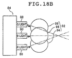
- the point-like light source is configured by using an RGB-LED including a red light emitting diode, a green light emitting diode, and a blue light emitting diode, and a plurality of lenses arranged correspondingly to light exist sides of the red light emitting diode, the green light emitting diode, and the blue light emitting diode.
- each of the plurality of lenses comprises a spherical transparent ball lens.
- the unitary light guide plate includes a plurality of diffusion reflectors in at least one of the light exit plane, the backside, and the lateral plane. And, preferably, the plurality of diffusion reflectors are arranged more densely with an increasing distance from the light entrance portion. Further, preferably, the plurality of diffusion reflectors are arranged on the backside.
- a third embodiment of the second aspect of the present invention provides a liquid crystal display device, comprising: the planar lighting device according to the second embodiment of the second aspect of the present invention; a liquid crystal display panel disposed on a light exit plane side of the unitary light guide plate of the planar lighting device; and a drive unit for driving the liquid crystal display panel.
- the light guide plate is thin and lightweight, emission efficiency of light from the light exit plane with respect to light emitted from the light source can be increased, and a size of the light exit plane of the light guide plate can be set larger.
- the thin and lightweight planar lighting device can be manufactured at a lower cost, which enables an increase in emission efficiency of light emitted from the light exit plane with respect to light emitted from the light source, and setting of an illumination surface to a large size, or which can be applied to a liquid crystal display device such as a wall-mounted television.
- light entered from the light entrance plane can reach a farther position in the light guide plate.
- a uniform illumination light having no brightness unevenness can be emitted, and thinning, weight-reduction, and enlargement are enabled.
- liquid crystal display device of the third embodiment of the second aspect of the present invention by installing the planar lighting device to obtain an illumination light of uniform brightness, good displaying can be carried out, and thinning, weight-reduction, and enlargement are enabled.
- FIG. 1 is a schematic view of an embodiment of a planar lighting device of the present invention.
- FIG. 2A is a front view of the planar lighting device of the present invention illustrated in FIG. 1 .
- FIG. 2B is a bottom view of the planar lighting device of the present invention illustrated in FIG. 1 .
- FIG. 2C is a lateral view of the planar lighting device of the present invention illustrated in FIG. 1 .
- FIG. 2D is a rear view of the planar lighting device of the present invention illustrated in FIG. 1 .
- FIG. 3 is a schematic sectional view of a lighting device main body which uses a light guide plate unit 18 of the present invention.
- FIG. 4A is a schematic perspective view of a configuration of an LED array.
- FIG. 4B is a schematic perspective view of a configuration of an LED array different from that of FIG. 4A .
- FIG. 4C is a schematic top view of a configuration of an LED chip.
- FIG. 5A is a schematic perspective view of a lighting device main body of a unitary light guide plate portion of the present invention.
- FIG. 5B is a schematic partial sectional view of the lighting device main body of the unitary light guide plate portion of the present invention.
- FIG. 6A is a schematic perspective view of a lighting device main body of the unitary light guide plate portion of the present invention.
- FIG. 6B is a schematic partial sectional view of the lighting device main body of the unitary light guide plate portion of the present invention.
- FIGS. 7A to 7D are conceptual views illustrating examples of sectional shapes of parallel grooves of the light guide plate unit of the present invention, and other embodiments of light entrance portions of the light guide plate.
- FIG. 8 is a schematic sectional view of a part of the unitary light guide plate or light guide plate unit of the present invention which includes a low refractive-index member.
- FIG. 9A is a schematic sectional view of another embodiment of a light guide plate unit of the present invention.
- FIG. 9B is a schematic sectional view of another embodiment of a unitary light guide plate of the present invention.
- FIG. 10A is a schematic perspective view of an example of a liquid crystal display device which includes the planar lighting device of the present invention.
- FIG. 10B is a schematic sectional view of the example of the liquid crystal display device which includes the planar lighting device of the present invention.
- FIG. 11A is a schematic perspective view of an example of a unitary light guide plate used for the planar lighting device of the present invention.
- FIG. 11B is a schematic perspective view of the example of the unitary light guide plate used for the planar lighting device of the present invention.
- FIG. 11C is a schematic sectional view of the example of the unitary light guide plate used for the planar lighting device of the present invention.
- FIG. 12 is a schematic side view illustrating an example of a configuration of the LED array used by the present invention.
- FIG. 13A is a schematic side view of another example of a unitary light guide plate used for the planar lighting device of the present invention.
- FIG. 13B is a schematic top view of the another example of the unitary light guide plate used for the planar lighting device of the present invention.
- FIG. 13C is a schematic back view of the another example of the unitary light guide plate used for the planar lighting device of the present invention.
- FIG. 14 is a schematic back view illustrating a unitary light guide plate which includes diffusion reflectors printed on the backside thereof.
- FIG. 15 is a schematic top view illustrating a light guide plate complex formed by combining a plurality of sets of unitary light guide plates illustrated in FIGS. 11 .
- FIG. 16 is a schematic top view illustrating another example of a light guide plate complex used for the planar lighting device of the present invention.
- FIG. 17A is a schematic top view illustrating an example of a light guide plate disposed in a space generated in the light guide plate complex of the present invention.
- FIG. 17B is a schematic side view illustrating the example of the light guide plate disposed in the space generated in the light guide plate complex of the present invention.
- FIG. 18A is a schematic view of an RGB-LED and a coupling lens.
- FIG. 18B is a schematic view of the RGB-LED and the coupling lens.
- a unitary light guide plate, a light guide plate unit, and a planar lighting device using these according to the first aspect of the present invention are described below in detail based on preferred aspects illustrated in attached drawings.
- FIG. 1 is a schematic perspective view illustrating the exterior of the planar lighting device according to the third embodiment of the present invention, which is a first aspect of the present invention, seen from a light exit plane side.
- FIGS. 2A , 2 B, 2 C and 2 D are each a front view, a bottom view, a lateral view, and a rear view of the planar lighting device illustrated in FIG. 1 .
- the planar lighting device is illustrated under magnification in a thickness direction thereof for ease of understanding.
- a planar lighting device 10 includes a lighting device main body 11 including a plurality of linear light sources 12 and emitting uniform light from a rectangular light exit plane 11 a , a housing 13 accommodating the lighting device main body 11 therein and including a rectangular opening 13 a on a side of the light exit plane 11 a (surface side), an inverter accommodating portion 9 provided on a side of the housing 13 opposite to the light exit plane 11 a (rear side) and accommodating a plurality of inverter units 8 each used to turn on the plurality of linear light sources 12 , and a power supply (not shown) connected to the plurality of inverter units 8 accommodated in the inverter accommodating portion 9 and each turning on the plurality of linear light sources 12 .
- FIG. 3 is a schematic sectional view illustrating a lighting device main body 11 which uses a light guide plate unit 18 of the second embodiment of the first aspect of the present invention configured by coupling a plurality of unitary light guide plates 19 or 20 of the first embodiment of the first aspect of the present invention in parallel.
- the lighting device main body 11 is for emitting uniform light from a rectangular light exit plane 11 a , and basically configured, as illustrated in FIG. 3 , so as to form a rectangular light exit plane 18 a on the light exit plane 11 a side by coupling a plurality of linear light sources 12 and a plurality of unitary light guide plates 19 or 20 of the first embodiment of the first aspect of the present invention in parallel, and includes a light guide plate unit 18 having a plurality of parallel grooves 18 f formed on the backside of the light exit plane 18 a to accommodate the linear light sources 12 , two prism sheets 16 and 17 arranged on the light exit plane 18 a side of the light guide plate unit 18 , and a diffusion sheet 14 .
- the lighting device main body 11 is constituted of the light guide plate unit 18 of the second embodiment of the first aspect of the present invention, and needless to say, the two prism sheets 16 and 17 and the diffusion sheet 14 arranged over the light guide plate unit 18 all have sizes (areas) substantially equal to that of the light exit plane 18 a of the light guide plate unit 18 .
- the linear light source 12 includes linear light sources 12 a disposed in the parallel grooves 18 f formed in the light guide plate unit 18 for emitting light from both sides toward the opposing wall planes of the parallel groove 18 f , and linear light sources 12 b disposed in both parallel end planes 18 g of the light guide plate unit 18 to emit light from one side toward each parallel end plane 18 g.
- the linear light source 12 a includes an LED array 24 a linearly extending in one direction (depth direction in the illustrated example), and a plurality of coupling lenses 28 arranged for a plurality of LED elements (refer to FIG. 4A ) linearly arranged at predetermined intervals in both lateral planes of the extending direction of the LED array 24 a .
- the LED array 24 a includes a plate-like heat sink 27 a extending in one direction, and a plurality of LED chips (LED elements) 25 arranged at predetermined intervals to face both lateral planes of the heat sink 27 a.
- the linear light source 12 b includes an LED array 24 b (refer to FIG. 4B ) including a substantially half-width plate-like heat sink 27 b extending in one direction (deep direction in the illustrated example of FIG. 3 ) and a plurality of LED chips 25 arranged at predetermined intervals in one lateral plane of the heat sink 27 b , and a plurality of coupling lenses 28 (refer to FIG. 3 ) arranged for the plurality of LED chips 25 of the LED array 24 b .
- the LED array 24 b illustrated in FIG. 4B has a shape where the LED array 24 a of FIG. 4A is substantially halved in a longitudinal direction (extending direction), and the linear light source 12 b has a shape substantially halved in the depth direction of the linear light source 12 a as illustrated in FIG. 3 .
- each of the heat sinks 27 a and 27 b supports the plurality of LED chips 25 in both lateral planes or one lateral plane of the longitudinal direction, and is preferably made of a highly heat conductive metal such as copper or aluminum so as to absorb heat generated from the plurality of LED chips 25 and to radiate the heat to the outside.
- each of the heat sinks 27 a and 27 b are linearly arranged, as illustrated in FIG. 3 , so as to face the opposing wall planes of the parallel groove 18 f of the light guide plate unit 18 and the parallel end planes of the light guide plate unit 18 .
- the present invention uses a heat sink as a support member for the LED chip
- the present invention is not limited thereto: where the LED chip does not need to be cooled, a plate member without a heat-releasing function may be used as the support member.
- a monochromatic LED configured to convert light emitted from the LED into white light by using a fluorescent substance is preferably used.
- white light can be obtained by using yttrium aluminum garnet (YAG) base fluorescent substance.
- the LED chip 25 has a rectangular shape so that the sides perpendicular to the direction in which the LED chips 25 are arrayed are shorter than the sides lying in the direction in which the LED chips 25 are arrayed or, in other words, the sides lying in the direction of thickness of the light guide plate unit 18 (direction perpendicular to the light exit plane 18 a ) are the shorter sides.
- the LED chip 25 has a shape satisfying b>a where “a” represents the length of the sides perpendicular to the light exit plane 18 a of the light guide plate unit 18 and “b” represents the length of the sides in the direction of the array.
- the LED chips 25 each given a rectangular shape allows the thickness of the light source to be reduced while maintaining output of a great amount of light.
- a thinner light source enables a thinner design of the planar lighting device 10 according to the present invention.
- the LED chips each preferably have a rectangular shape with the shorter sides lying in the direction of thickness of the light guide plate unit 18 to achieve a thinner design of the LED array, but the present invention is not limited thereto, allowing use of LED chips having various shapes such as a square, a circle, a polygon, and an ellipse.
- ball lenses are provided as coupling lenses 28 on the light exit side of the respective LED chips 25 of the LED arrays 24 a and 24 b .
- the coupling lenses 28 are disposed correspondingly to the respective LED chips 25 .
- Light emitted by the individual LED chip 25 is collimated by the coupling lenses 28 before entering an inner surface of the light guide plate unit 18 .
- coupling lenses While ball lenses are used as coupling lenses here, no specific limitations are placed on the coupling lenses, provided that they are capable of collimating light emitted by the LEDs.
- the coupling lenses for example, a cylindrical lens, a lenticular lens, a half-cylindrical lens, a Fresnel lens can also be used.
- An LD laser diode
- An LD laser diode
- the light guide plate unit 18 of the second embodiment of the first aspect of the present invention can be configured by, as described above, in FIG. 3 , coupling a plurality of unitary light guide plates 19 obtained by dividing the light guide plate unit 18 by dotted lines (refer to FIGS. 5A and 5B ) in parallel in a direction orthogonal to the parallel grooves 18 f so that light exit planes 19 a thereof can be coupled as a flat plane, or coupling a plurality of unitary light guide plates 20 obtained by dividing the light guide plate unit 18 by chain lines (refer to FIGS.
- FIGS. 5A and 5B are a schematic perspective view and a schematic partial sectional view of a part of the unitary light guide plate 19 of the first aspect of the present invention, which becomes one unit constituting the light guide plate unit 18 .
- the unitary light guide plate 19 of the first embodiment of the first aspect of the present invention includes a rectangular light exit plane 19 a , a thick portion 19 b located substantially in the center of the light exit plane 19 a in parallel to one side of the light exit plane 19 a , thin end portions 19 c formed at both ends of the thick portion 19 b in parallel to the thick portion 19 b , a half 19 d of the parallel groove 18 f formed in the backside of the thin end portion 19 c of the light exit plane 19 a to accommodate a linearly arranged light source 12 b , and inclined backsides 19 e disposed in both sides of the thick portion 19 b to be gradually thinner from the thick portion 19 b toward the thin end portion 19 c along a direction orthogonal to the parallel groove 18 f (the one side).
- the unitary light guide plate 19 has the rectangular light exit plane 19 a , and made of a transparent resin.
- the unitary light guide plate 19 has one plane to become the light exit plane 19 a which is formed flat and other planes incline so as to be thinner from the thick portion 19 b substantially located in the center toward the thin end portions 19 c at both ends.
- the unitary light guide plate 19 includes scattering means for scattering light emitted from the light source 12 and propagated through the unitary light guide plate 19 . Note that the scattering means is described below.
- the halves 19 d of the parallel groove 18 f are formed in the thin end portions 19 c at both sides of the backside of the light exit plane 19 a of the unitary light guide plate 19 .
- forming positions are not limited to both sides.
- a half 19 d may be formed in one of the thin end portions 19 c in the backside of the light exit plane 19 a.
- a light guide plate unit 18 is configured by using the unitary light guide plate 19 , as illustrated in FIG. 3 , two or more (four in the illustrated example) unitary light guide plates 19 (indicated by dotted lines of FIG. 3 ) of the present invention having the above-mentioned shape are coupled together so that light exit planes 19 a can form flush plane (light exit plane 18 a ) and, in a direction orthogonal to a parallel groove 18 f (horizontal direction in the drawing), halves 19 d of parallel grooves 18 f of the adjacent unitary light guide plates 19 can form parallel grooves 18 f for accommodating linearly arranged light sources 12 b .
- the light guide plate unit 18 of the second embodiment of the first aspect of the present invention is formed.
- FIGS. 6A and 6B are a schematic perspective view and a schematic partial sectional view of the unitary light guide plate 20 of the first embodiment of the first aspect of the present invention which becomes one unit constituting the light guide plate unit 18 .
- the unitary light guide plate 20 of the first embodiment of the first aspect of the present invention includes a rectangular light exit plane 20 a , a thin portion 20 b located substantially in the center of the light exit plane 20 a in parallel to one side of the light exit plane 20 a , thick end portions 20 c formed at both ends of the thin portion 20 b in parallel to the thin portion 20 b , a parallel groove 18 f formed in the thin portion 20 b in the backside of the light exit plane 20 a in parallel to the one side to accommodate a linearly arranged light source, and inclined backsides 20 d disposed at both sides of the thin portion 20 b to be gradually thicker from the thin portion 20 b toward the thick end portions 20 c along a direction orthogonal to the one side.
- the unitary light guide plate 20 is a flat plate having a rectangular surface, and made of a transparent resin.
- the unitary light guide plate 20 includes one plane formed flat and the other plane having the parallel groove 18 f in the thin portion 20 b substantially located in the center and inclining such that the plate 20 has a thickness thinner from the thin portion 20 b toward the thick end portions 20 c at both ends.
- the unitary light guide plate 20 includes scattering means for scattering light emitted from the light source 12 and propagated through the unitary light guide plate 20 .
- a light guide plate unit 18 is configured by using the above-mentioned unitary light guide plate 20 , as illustrated in FIG. 3 , by coupling two or more (four in the illustrated example) unitary light guide plates 20 (indicated by dotted lines of FIG.
- a light guide plate unit 18 of the second embodiment of the first aspect of the present invention is formed.
- the half portions 20 f of the unitary light guide plate 20 are formed by dividing the unitary light guide plate 20 into two equal parts in the direction orthogonal to the parallel groove 18 f.
- the light guide plate unit 18 is formed by coupling the thick end portions of the half portions 20 f of the unitary light guide plates 20 to the thick end portions at both ends of the coupled unitary light guide plate 20 .
- the present invention is not limited to this. Without coupling anything to the thick end portions at both ends of the coupled unitary light guide plate 20 , a reflection film 22 described below may be disposed.
- the light guide plate unit 18 of the second embodiment formed by using the unitary light guide plate 19 or 20 of the first embodiment of the first aspect of the present invention and having the above-mentioned shape among light emitted from the light sources 12 a disposed in the parallel grooves 18 f or the light sources 12 b disposed in the end planes of the light guide plate unit 18 in the direction orthogonal to the parallel grooves 18 f , light entered through side walls constituting the parallel groove 18 f or the end planes into the light guide plate unit 18 passes inside the light guide plate unit 18 to exit from the light exit plane 18 a , or is reflected on the inclined planes 18 b to exit from the light exit plane 18 a .
- the light guide plate unit 18 is formed to be gradually thicker in the direction orthogonal to the parallel groove 18 f from the parallel groove 18 f in which the light source 12 a is disposed or the end plane of the light guide plate unit 18 , along which the light source 12 b is disposed, in the direction orthogonal to the parallel groove 18 f , toward a substantially middle point (coupled portion of the thick portions of the unitary light guide plate 19 or the thick end portions of the unitary light guide plate 20 ) between the adjacent parallel grooves 18 f or between the end plane and the parallel groove 18 f adjacent to each other, whereby light entered to the light guide plate unit 18 can reach far.
- the light guide plate unit 18 can be made thinner than a light guide plate of a flat plate shape or a wedge shape.
- the light guide plate unit 18 enables light emitted from the light source to reach far, and can be thinned and reduced in weight. That is, since incident angles are gradually made shallow in the case of full reflection, and light is difficult to exit from the light exit plane to the outside, an incident light can reach deeper. Accordingly, the planar lighting device can be reduced in weight, thinned, and enlarged. Thinning the light guide plate unit 18 can make the light guide plate unit 18 itself flexible. As a result, by combining the light guide plate unit 18 with a flexible liquid crystal, a flexible LCD monitor or a flexible television (TV) can be realized.
- a flexible liquid crystal a flexible LCD monitor or a flexible television (TV) can be realized.
- a depth of the parallel groove 18 f of the light guide plate unit 18 is set so as to prevent bulging of a part of the light source 12 a from the bottom plane of the light guide plate unit 18 , and is set in view of a size of the light source 12 a , mechanical strength of the light guide plate unit 18 , and time-depending changes.
- a thickness of the light guide plate unit 18 can be optionally changed according to the size of the light source 12 .
- a sectional shape of the parallel groove 18 f of the light guide plate unit 18 is not limited to a triangle illustrated in each of FIGS. 3 , 6 A and 6 B, and 7 A.
- a shape illustrated in FIG. 7B where a tip of a triangle is round, a parabolic shape illustrated in FIG. 7C , or a shape illustrated in FIG. 7D , which is formed from two convex curves formed toward the center of the parallel groove 18 f may be employed. Any shape can be used as long as the parallel groove 18 f can accommodate the light source 12 b.
- any shape can be used for the light guide plate unit 18 as long as a thickness of the light guide plate unit 18 is made gradually larger in the direction orthogonal to the parallel groove 18 f from the parallel groove 18 f or the end plane of the light guide plate unit 18 in the direction orthogonal to the parallel groove 18 f , toward the substantially middle point (coupled portion of the thick portions of the unitary light guide plate 19 or the thick end portions of the unitary light guide plate 20 ) between the adjacent parallel grooves 18 f or between the end plane of the light guide plane unit 18 in a direction orthogonal to the adjacent parallel grooves 18 f and the parallel groove 18 f .
- the inclined plane 18 b (inclined backside 19 e or 20 d ) located on the backside of the light exit plane 18 a of the light guide plate unit 18 may be curved.
- the light guide plate unit 18 is configured, as described above, by coupling the unitary light guide plates 19 or 20 only in the direction orthogonal to the parallel grooves 18 f .
- the configuration is not limited to this. Two or more light guide plate units 18 may be coupled together so as to array the parallel grooves 18 f thereof collinearly in a direction parallel to the parallel groove 18 f.
- the unitary light guide plate 19 or 20 is described more in detail.
- the unitary light guide plate 19 is described as a representative example, and different portions thereof are described individually.
- Characteristics described here of the unitary light guide plates 19 and 20 are characteristics of the unitary light guide plate unit 18 configured by using these. Thus, needless to say, similar effects can be obtained.
- the depth and the sectional shape of the parallel groove 18 f and the diffusion reflector of the light guide plate unit 18 described above apply to the unitary light guide plates 19 and 20 .
- the unitary light guide plate 19 in other words, the light guide plate unit 18 , includes scattering means for scattering light emitted from the light source 12 and propagated through the unitary light guide plate 19 .
- this scattering means There is no limitation on this scattering means, as long as it can sufficiently propagate the light entered into the unitary light guide plate 19 .
- the scattering means is scattering particles which satisfy the following Expressions (1) and (2): 1.1 ⁇ N P ⁇ L G ⁇ K C ⁇ 8.2 (1) 0.005 ⁇ K C ⁇ 0.1 (2) where, ⁇ denotes a scattering cross section of the scattering particles, N P denotes a density of the scattering particles contained in the unitary light guide plate, L G denotes a length half of one side of the light exit plane in the direction orthogonal to the parallel groove, and K C denotes a compensation coefficient).
- the light guide plate unit 18 contains the scattering particles which satisfy such a relationship. Thus, a uniform illumination light of little brightness unevenness can be emitted from the light exit plane.
- a length L G of a half of the light guide plate in the optical axial direction is a length from one light entrance plane of the light guide plate unit 18 to the center of the light guide plate unit 18 in a direction perpendicular to the light entrance plane of the light guide plate unit 18 .
- the light extraction efficiency is a ratio of light reaching a position away from the light entrance plane of the light guide plate in the optical axial direction by a length L G with respect to incident light.
- the light extraction efficiency is a ratio of light reaching the center of the unitary light guide plate 19 (position which becomes a length of a half of the light guide plate in the optical axial direction) with respect to light incoming to the end plane: E out ⁇ exp( ⁇ N p ⁇ L G ) (9)
- Expression (9) applies in a space having limited dimensions, and thus the compensation coefficient K C for compensating the relation with Expression (7) is introduced.
- the compensation coefficient K C obtained empirically, is a dimensionless compensation coefficient that applies to light propagating through an optical medium having limited dimensions. Accordingly, the light extraction efficiency E out is expressed by the following Expression (10).
- E out exp( ⁇ N p ⁇ L G ⁇ K C ) (10)
- light emitted through the plane opposed to the light entrance plane can be reduced, and hence, light emitted from the light exit plane can be increased, by increasing the value ⁇ N p ⁇ L G ⁇ K C .
- the ratio of light emitted through the light exit plane with respect to the light incident on the entrance plane (hereinafter, also referred to as “light use efficiency”) can be enhanced by increasing the value ⁇ N p ⁇ L G ⁇ K C .
- the light use efficiency can be enhanced to 50% or more by setting the value ⁇ N p ⁇ L G ⁇ K C to 1.1 or larger.
- illuminance unevenness of light emitted through the light exit plane 18 a of the light guide plate 18 becomes more conspicuous.
- the illuminance unevenness can be held to a certain level or less (within an allowable range) by setting the value ⁇ N p ⁇ L G ⁇ K C to 8.2 or less.
- illuminance and brightness can be treated substantially equally. Thus, it is assumed in the present invention that illuminance and brightness possess similar tendencies.
- the value ⁇ N p ⁇ L G ⁇ K C preferably satisfies the relation to be 1.1 or more and 8.2 or less, and more preferably 2.0 or more and 7.0 or less. Still more preferably, the value ⁇ N p ⁇ L G ⁇ K C is 3.0 or more and, most preferably, 4.7 or more.
- the compensation coefficient K C is preferably 0.005 or more and 0.1 or less.
- the light guide plate unit 18 containing the scattering particles which satisfy the relationships of Expressions (1) and (2) enables appropriate scattering of the light entered into the light guide plate unit 18 in the light guide plate unit 18 . Breaking the full-reflection condition, in the light guide plate itself, a function of emitting light difficult to exit is provided. Thus, light emitted from the light exit plane can be made more uniform.
- the unitary light guide plate 19 is formed of a transparent resin into which scattering particles for scattering light are kneaded and dispersed.
- transparent resin materials used to form the unitary light guide plate 19 there are optically transparent resins such as polyethylene terephthalate (PET), polypropylene (PP), polycarbonate (PC), polymethyl methacrylate (PMMA), benzyl methacrylate, MS resins, and cycloolefin polymer (COP).
- the scattering particles kneaded and dispersed into the unitary light guide plate 19 for example, TOSPEARL (trademark), silicone, silica, zirconia, or a derivative polymer can be used.
- the unitary light guide plate 19 containing such scattering particles is capable of emitting uniform illumination light through the light exit plane with a reduced level of brightness unevenness.
- the unitary light guide plate 19 as described above can be manufactured using an extrusion molding method or an injection molding method.
- the unitary light guide plate 19 includes, in addition to the scattering means, transmittance adjusters added to the light exit plane 19 a side of the unitary light guide plate 19 (light exit plane 18 a side of the light guide plate unit 18 ). By appropriately adjusting an arrangement density of the transmittance adjusters, the more uniform light can be emitted.
- the unitary light guide plate 19 may be manufactured by mixing a plasticizer into the above-mentioned transparent resin.
- the unitary light guide plate 19 is made of materials containing a transparent material mixed with a plasticizer, the light guide plate unit 18 is given flexibility or pliability such that the light guide plate can be formed into various shapes.
- the surface of the light guide plate can be formed into various curved surfaces.
- the light guide plate unit 18 or a planar lighting device using the light guide plate unit 18 is used as a display board employing ornamental lighting (illuminations), it can also be mounted to a wall having a curvature.
- the light guide plate can be used for a wider variety of applications and in a wider application range including ornamental lighting and point-of-purchase (POP advertising).
- the plasticizer is exemplified by phthalic acid esters, or, specifically, dimethyl phthalate (DMP), diethyl phthalate (DEP), dibutyl phthalate (DBP), di(2-ethylhexyl) phthalate (DOP (DEHP)), di-n-octyl phthalate (DnOP), diisononyl phthalate (DINP), dinonyl phthalate (DNP), diisodecyl phthalate (DIDP), phthalate mixed-base ester (C 6 to C 11 ) (610P, 711P, etc.), and butyl benzyl phthalate (BBP).
- DMP dimethyl phthalate
- DEP diethyl phthalate
- DBP dibutyl phthalate
- DOP di(2-ethylhexyl) phthalate
- DOP DEHP
- DnOP diisononyl phthalate
- DNP dinonyl phthal
- the plasticizer is also exemplified by dioctyl adipate (DOA), diisononyl adipate (DINA), dinormal alkyl adipate (C 6, 8, 10 ) (610A), dialkyl adipate (C 7, 9 ) (79A), dioctyl azelate (DOZ), dibutyl sebacate (DBS), dioctyl sebacate (DOS), tricresyl phosphate (TCP), tributyl acetylcitrate (ATBC), epoxidized soybean oil (ESBO), trioctyl trimellitate (TOTM), polyesters, and chlorinated paraffins.
- DOA dioctyl adipate
- DINA diisononyl adipate
- 610A dinormal alkyl adipate
- C 7, 9 dialkyl adipate
- DOZ dioctyl azelate
- DBS dibutyl
- the unitary light guide plate 19 there is no particular limitation on surface roughness Ra of the unitary light guide plate 19 , in other words, surface roughness of the light exit plane 19 a of the unitary light guide plate 19 .
- Ra 1 denotes surface roughness of the light exit plane 19 a in a direction parallel to the parallel groove 18 f
- Ra 2 denotes surface roughness of the light exit plane 19 a in a direction orthogonal to the parallel groove 18 f: Ra 2 ⁇ Ra 1 and Ra 2 ⁇ 100 (3)
- an angle ⁇ formed when a plane parallel to the light exit plane 19 a of the unitary light guide plate 19 and the inclined plane of the inclined backside 19 e ( 20 d ) cross each other at a vertex of the thick portion 19 b (or thick end portion 20 c ) satisfies the following Expression (4): 0° ⁇ 45° (4)
- the unitary light guide plate 19 there is no particular limitation on a relationship between a maximum thickness T in a direction perpendicular to the light exit plane 19 a and a distance D between the adjacent light sources 12 a (or 12 a and 12 b ).
- the distance D between the adjacent light sources 12 a (or 12 a and 12 b ) is more than 10 times the maximum thickness in the direction perpendicular to the light exit plane 19 a , or less than 100 times the maximum thickness in the direction perpendicular to the light exit plane 19 a , emission efficiency can be maintained while keeping a brightness distribution of outgoing light.
- the following Expression (5) is satisfied: 10T ⁇ D 1 ⁇ 1,000T (5) where T denotes a maximum thickness of the unitary light guide plate, and D 1 denotes a distance between the light sources.
- any shape can be employed for the unitary light guide plate 19 , as long as one plane is flat, and the other plane is inclined such that the thickness of the plate is gradually thinner from the thick portion 19 b located in the substantial center toward the thin end portions 19 c at both ends.
- the inclined plane of the inclined portion 19 e of the unitary light guide plate 19 may be curved.
- any shape can be employed for the unitary light guide plate 20 , as long as one plane of the unitary light guide plate 20 is flat, and the other plane thereof has the parallel groove 18 f in the thin portion 20 b located in the substantial center and is inclined so as to be thinner from the thin portion 20 b toward the thick end portions 20 c of both ends.
- the inclined plane of the inclined backside 20 d of the unitary light guide plate 20 may be curved.
- incorporating a low refractive index member 30 having a lower refractive index than the base material of the unitary light guide plate 19 or 20 in a part including the entrance plane of the light from the light source 12 and admitting light emitted by the light source into the low refractive index member 30 enables reduction of Fresnel loss of light emitted by the light source and admitted through the light entrance plane, which increases the light admission efficiency.
- the low refractive index member 30 has a function to collimate and mix admitted light, i.e., a function performed by the coupling lens and the mixer.
- the backlight unit according to the first aspect, provided with the low refractive index member, allows light emitted by the light source 12 to reach a farther position without the coupling lens and the mixer and is capable of emitting uniform light free from brightness unevenness.
- the light exit plane 19 a or 20 a of the unitary light guide plate 19 or 20 is preferably formed of a low refractive index member substantially in its entirety.
- substantially the entire surface of the light exit plane is formed of a low refractive index member, light emitted by the light source and entering the light guide plate can be admitted into the low refractive index member, which further improves the light admission efficiency.
- the low refractive index member 30 of FIG. 8 has the shape of a half cylinder curving outward toward the plane opposite to the light entrance plane, the present invention is not limited thereto.
- an inclined angle of the inclined plane of the unitary light guide plate 19 or 20 can be adjusted so as to prevent crossing between the inclined plane of one unit light guide plane 19 or 20 and the inclined plane of the other unit light guide plane 19 or 20 coupled thereto, in other words, so as to form a smooth plane or curve in the coupled portion of the inclined planes.
- the light guide plate unit 18 , and the unitary light guide plates 19 and 20 are basically configured as described above.
- the diffusion sheet 14 is used to diffuse and render uniform the light emitted through the light exit plane 18 a of the light guide plate unit 18 .
- the diffusion sheet 14 is formed by imparting a light scattering property to a flat sheet material made of an optically transparent resin as exemplified by polyethylene terephthalate (PET), polypropylene (PP), polycarbonate (PC), polymethyl methacrylate (PMMA), benzyl methacrylate, MS resins, and other acrylic resins, and cycloolefin polymer (COP).
- PET polyethylene terephthalate
- PP polypropylene
- PC polycarbonate
- PMMA polymethyl methacrylate
- MS resins and other acrylic resins
- COP cycloolefin polymer
- a surface of the flat-plate material may be roughened to impart the light scattering property by machining to provide an asperity on the surface or by grinding (a surface subjected to such roughening is hereinafter referred to as “sand-rubbed surface”).
- the diffusion sheet may be alternatively formed by coating its surface with a material that diffuse light as exemplified by silica, pigments such as titanium oxide and zinc oxide, a resin, and beads of glass, zirconia, etc., together with a binder, or by kneading the above-mentioned pigments or beads having a light scattering property into the above-mentioned resin.
- a diffusion sheet of a matte type or a coating type can be used as the diffusion layer 14 .
- the diffusion sheet 14 it is also preferable to use a film material with a thickness of 500 ⁇ m or less using the above-mentioned material and imparted with light scattering property.
- the diffusion sheet 14 is disposed on the light exit plane side of the prism sheet 17 .
- the diffusion sheet 14 is formed by imparting a light diffusing property to a material in the form of film.
- the material in the form of film may be formed, for example, of an optically transparent resin such as polyethylene terephthalate (PET), polypropylene (PP), polycarbonate (PC), polymethyl methacrylate (PMMA), benzyl methacrylate, an MS resin, or cycloolefin polymer (COP).
- the method of manufacturing the diffusion sheet 14 is not limited specifically.
- a surface of the material in the form of film may be machined to form an asperity thereon or roughened by grinding, thereby to provide a light diffusing property, or by coating the surface with a material that diffuses light as exemplified by silica, pigments such as titanium oxide and zinc oxide, a resin, and beads of glass, zirconia, etc., together with a binder, or by kneading the above-mentioned pigments or beads that diffuse light into the transparent resin.
- a material having a high reflectance and a low light-absorbing property such as metals as exemplified by Ag and Al can be used to form the diffusion sheet 14 .
- a diffusion film of a matte type or a coating type may be used as the diffusion sheet 14 .
- the diffusion sheet 14 is disposed a given distance apart from the light exit plane 18 a of the light guide plate unit 18 .
- the distance may be altered as appropriate according to the light amount distribution of light emitted from the light exit plane 18 a of the light guide plate unit 18 .
- the diffusion sheet 14 spaced apart a given distance from the light exit plane 18 a of the light guide plate unit 18 , the light emitted from the light exit plane 18 a of the light guide plate unit 18 is subjected to further mixing (mixture) between the light exit plane 18 a and the diffusion sheet 14 . This further enhances the uniformity of brightness of the light passing through the diffusion sheet 14 to illuminate the liquid crystal display panel 4 .
- the method of spacing the diffusion sheet 14 from the light guide plate unit 18 a of the light guide plate unit 18 by a given distance for example, the method of providing a spacer between the diffusion sheet 14 and the light guide plate unit 18 can be used.
- the peak value of brightness on the light exit plane 18 a of the light guide plate unit 18 corresponding to the parallel groove 18 f does not need to be reduced sufficiently by providing a certain sectional shape of the parallel groove 18 f of the light guide plate unit 18 , and uniformity of the brightness distribution of the illumination light emitted from the diffusion sheet 14 may be achieved by reducing the peak value only partially and providing a gap between the diffusion sheet 14 and the light exit plane 18 a of the light guide plate unit 18 .
- a gap may be provided between the diffusion sheet 14 and the light exit plane 18 a of the light guide plate unit 18 to render uniform the brightness distribution of the illumination light emitted from the diffusion sheet 14 .
- the prism sheets 16 and 17 are transparent sheets formed by arranging a plurality of prisms in parallel and enhance the light harvesting property of the light emitted from the light exit plane 18 a of the light guide plate unit 18 to improve the brightness.
- One of the prism sheets 16 and 17 is disposed such that its prism array extends parallel to the parallel groove 18 f of the light guide plate unit 18 whereas the other is disposed such that its prism array extends perpendicular to the parallel groove 18 f of the light guide plate unit 18 .
- the prism sheets 16 and 17 are disposed such that their respective prism arrays extend in directions perpendicular to each other.
- the prism sheet 16 is provided such that the vertex angles of the prisms face the light exit plane 18 a of the light guide plate unit 18 .
- the order of arranging the prism sheets 16 and 17 may be such that the prism sheet 16 having prisms that extend in a direction parallel to the parallel groove of the light guide plate is provided immediately above the light guide plate and that the prism sheet 17 having prisms that extend in a direction perpendicular to the parallel groove 18 f of the light guide plate unit 18 is provided on top of the prism sheet 16 .
- the order of arrangement of the two prism sheets may be reversed.
- prism sheets are used in the illustrated case, they may be replaced with sheets on which optical elements similar to the prisms are regularly arranged.
- sheets on which elements having lens effects, for example, lenticulated lenses, concave lenses, convex lenses, or optical elements in pyramidal shape are regularly arranged may be substituted for the prism sheets.
- a prism sheet is disposed between the reflection film 22 described below and the inclined plane 18 d of the light guide plate unit 18 .
- the prism sheet (not shown) disposed between the reflection film 22 and the inclined plane 18 d of the light guide plate unit 18 is preferably arranged so that an extending direction of the prism is perpendicular to the parallel groove 18 f of the light guide plate unit 18 and a vertex angle of the prism face the inclined plane 18 b of the light guide plate unit 18 .
- optical elements having effects similar to those of prisms may be used.
- a sheet on which optical elements having lens effects such as lenticular lenses, concave lenses, convex lenses, or pyramid-shaped lenses are arranged regularly may be used.
- the prism sheets 16 and 17 are used, and more preferably, the prism sheet is used between the reflection film 22 and the inclined plane 18 d of the light guide plate unit 18 .
- the prism sheets are unnecessary, and the prism sheet 16 or 17 or both may be dispensed with. Using a smaller number of expensive prism sheets or dispensing with all these prism sheets contributes to reducing the costs for the device.
- prism sheets having prism arrays formed thereon are disposed on the light exit plane 18 a
- like effects may be obtained by forming prism arrays on the inclined plane 18 b of the light guide plate unit 18 .
- prism arrays formed on the inclined plane also help condense the light emitted through the light exit plane 18 a to improve brightness.
- optical elements similar to prisms may be formed regularly. For example, lenticular lenses, concave lenses, convex lenses, or an optical element in pyramidal shape having lens effects may be formed on the inclined plane of the light guide plate.
- the reflection film 22 is for reflecting light leaked from the inclined plane 18 b of the light guide plate unit 18 to enter the light to the light guide plate unit 18 again, and can increase light emission efficiency.
- the reflection film 22 is formed to cover the inclined plane 18 b of the light guide plane unit 18 or the lateral plane thereof when necessary.
- the reflection films 22 may be formed of any material that is capable of reflecting the light leaking from the inclined plane 18 b of the light guide plate unit 18 . It may be formed, for example, of a resin sheet produced by kneading PET, polypropylene (PP), etc. with a filler and then drawing the resultant mixture to form voids therein to increase the reflectance, a sheet with a specular surface formed by, for example, depositing aluminum vapor on the surface of a transparent resin sheet or a white resin sheet as described above, a metal foil such as an aluminum foil, or a resin sheet carrying a metal foil, or a metal thin plate having sufficient reflective property on the surface.
- a resin sheet produced by kneading PET, polypropylene (PP), etc. with a filler and then drawing the resultant mixture to form voids therein to increase the reflectance
- a sheet with a specular surface formed by, for example, depositing aluminum vapor on the surface of a transparent resin sheet or a white resin sheet
- a reflector may be disposed in order to reflect light from the bottom plane of the light source 12 b and to enter the light from the inside of the parallel groove 18 f of the light guide plate unit 18 .
- the reflector can be made of, for example, a material similar to that of the reflection film, in other words, a resin material, metallic foil, or a metal plate each having sufficient reflectivity on its surface, and there is no particular limitation on its shape.
- a transmittance adjusting member having a function of reducing brightness unevenness of a light emitted from the light exit plane 14 a may be disposed on the light exit plane 14 a side of a planar lighting device 2 which is the third embodiment of the first aspect of the present invention.
- the transmittance adjusting member is used for reducing brightness unevenness of light emitted from the light guide plate unit 18 as described above, and normally includes a transparent film and many transmittance adjusters disposed in a surface of the transparent film. There is no limitation on this transmittance adjusting member in this embodiment.
- the transmittance adjusting member is used to reduce brightness unevenness of light emitted from the light guide plate unit 18 and includes a transparent film and numerous transmittance adjusters arranged on the surface of the transparent film.
- the transparent film is in the form of a film and formed of optically transparent resins such as polyethylene terephthalate (PET), polypropylene (PP), polycarbonate (PC), polymethyl methacrylate (PMMA), benzyl methacrylate, MS resins, other acrylic resins, or cycloolefin polymer (COP).
- optically transparent resins such as polyethylene terephthalate (PET), polypropylene (PP), polycarbonate (PC), polymethyl methacrylate (PMMA), benzyl methacrylate, MS resins, other acrylic resins, or cycloolefin polymer (COP).
- the transmittance adjusters are dots of various sizes each having a given transmittance and have various shapes such as a rectangle, a circle, and a hexagon.
- the transmittance adjusters are formed, by printing for example, on the entire surface of the transparent film on the light guide plate unit 18 side in a given pattern, or in such a pattern, for example, that the sizes of dots or the number of dots vary according to the location (halftone dot pattern).
- the transmittance adjusters only need to be diffusion reflectors and may, for example, be formed by applying a material that diffuses light as exemplified by silica, pigments such as titanium oxide and zinc oxide, a resin, and beads of glass, zirconia, etc., together with a binder, or may be a pattern created by machining a surface to form an asperity thereon or by grinding a surface to roughen the surface. Otherwise, a material having a high reflectance and a low light-absorbing property, such as metals as exemplified by Ag and Al can be used.
- ordinary white ink as used in screen printing, offset printing, etc can be used.
- ink obtained by dispersing titanium oxide, zinc oxide, zinc sulfate, barium sulfate, etc. into acrylic binder, polyester binder, vinyl chloride binder, etc., or ink given a diffusing property by mixing titanium oxide with silica can be used.
- a light emission distribution of the light source 12 is preferably larger in the direction (horizontal direction in FIG. 1 ) orthogonal to the parallel groove 18 f than in the ceiling direction (upward in FIG. 1 ) of the parallel groove 18 f of the light guide plate unit 18 .
- the LED that emits a white light is used.
- the present invention is not limited to this.
- a white color can be obtained by using LEDs of three colors of red, green, and blue, and mixing light emitted from the LEDs via a coupling lens.
- the LED is used for the light source.
- point-like light sources such as semiconductor lasers (LD), tungsten lamps, or xenon lamps may be linearly arrayed along the parallel grooves 18 f .
- a distance D 2 between the point-like light sources satisfies the following Expression (6): 10 mm ⁇ D 2 (6)
- a linear light source such as a fluorescent tube, a cold cathode tube, a hot cathode tube, or an external electrode tube may be used.
- the light sources 12 b are arranged in both end planes of the light guide plate unit 18 in the direction orthogonal to the parallel groove 18 f .
- the present invention is not limited to this.
- Light sources 12 a may be disposed only in the parallel grooves 18 f.
- FIGS. 9A and 9B illustrate another example of a light guide plate unit.
- FIG. 9A is a schematic sectional view of another aspect of the light guide plate unit 18 of the second embodiment of the first aspect of the present invention
- FIG. 9B is a schematic sectional view of a unitary light guide plate constituting the light guide plate unit illustrated in FIG. 9A .
- the light guide plate unit 32 is configured by coupling together a plurality of unitary light guide plates 34 as in the case of the light guide plate unit 18 configured by coupling together the plurality of unitary light guide plates 19 or 20 .
- the unitary light guide plate 34 includes substantially rectangular light exit planes 36 a and 36 b , an inclined plane 38 b located on a side opposed to the light exit plane 36 b and inclined at a predetermined angle with respect to the light exit plane 36 b sandwiching a light source 36 , a light entrance plane 40 b away from the light source 36 by an amount substantially equal to the light exit plane, a light entrance plane 40 a parallel to the light entrance plane 40 b having its top portion brought into contact with the light source 36 , and an inclined plane 38 a located on a side opposed to the light entrance plane 36 a and inclined at a predetermined angle with respect to the light exit plane 36 a sandwiching a light source 41 .
- the unitary light guide plate having this configuration can spread the light emitted from the light source to the unitary light guide plates located at both left and right sides in the drawing.
- the light guide plate unit 32 is formed by coupling the light entrance plane of the adjacent unitary light guide plate and the light source to each other, and thus the plurality of unitary light guide plates 34 are integrally formed to have a coupled shape.
- the light guide plate unit 32 is arranged to have all the light exit planes in parallel to form the same plane.
- Coupling the plurality of unitary light guide plates 34 in this manner enables configuration of a large light guide plate.
- the first aspect of the present invention is basically as described above.
- a plurality of diffusion reflectors may be formed, by printing for example, on the inclined plane 18 b of the light guide plate unit 18 , which is located on a rear side of the light exit plane 18 a , illustrated in FIG. 3 in a given pattern, specifically in such a pattern that the density is high in the vicinity of the parallel groove 18 f of the light guide plate unit 18 , that is, in the vicinity of the linear light source 12 , and the density decreases toward substantially the center of the parallel groove 18 f and the parallel groove 18 f or toward substantially the center located between the parallel groove 18 f and the end plane of the light guide plate unit 18 in a direction perpendicular to the parallel groove 18 f , that is, decreases as the thickness of the light guide plate unit 18 f becomes thicker.
- Such diffusion reflectors formed on the inclined plane 18 b of the light guide plate unit 18 in a given pattern can limit generation of bright lines or unevenness in the light exit plane 18 a of the light guide plate unit 18 .
- a thin sheet including the diffusion reflectors formed thereon in a given pattern may be disposed between the inclined plane 18 b of the light guide plate unit 18 and the reflection sheet 22 described below.
- the diffusion reflectors may each have any shape such as a rectangle, a polygon, a circle, and an ellipse.
- the diffusion reflectors may be formed, for example, by applying a material for diffusing light as exemplified by silica, pigments such as titanium oxide and zinc oxide, a resin, and beads of glass, zirconia, etc., together with a binder, or may be a pattern created by machining the surface to form an asperity thereon or by grinding to roughen the surface. Otherwise, a material having a high reflectance and a low light-absorbing property, such as metals as exemplified by Ag and Al may be used. Further, as the diffusion reflectors, ordinary white ink as used in screen printing, offset printing, etc. may be used.
- ink obtained by dispersing titanium oxide, zinc oxide, zinc sulfate, barium sulfate, or the like into acrylic binder, polyester binder, vinyl chloride binder, or the like, or ink given a diffusing property by mixing titanium oxide with silica may be used.
- the present invention is not limited thereto and may be determined as appropriate according to the intensity or distribution of bright lines, brightness distribution required of emitted light, etc.
- the diffusion reflectors may be distributed evenly on the entire surface of the inclined planes or at a density that decreases with the increasing distance from the light entrance plane. Further, instead of providing the diffusion reflectors by printing, the locations corresponding to the diffusion reflectors may be roughened to provide sand-rubbed surfaces.
- the diffusion reflectors are not limited to be provided on the inclined plane of the light guide plate unit 18 , and may be provided on any plane as desired except the light entrance plane.
- the diffusion reflectors may be provided on the light exit plane 18 a or on the inclined plane 18 b and the plane opposite to the light entrance plane.
- FIG. 10A is a schematic perspective view of a liquid crystal display device provided with the planar lighting device (hereinafter, referred to as backlight unit) according to the first embodiment in the second aspect of the present invention
- FIG. 10B is a schematic sectional view of the liquid crystal display device.
- a liquid crystal display device 50 includes a backlight unit 42 , a liquid crystal display panel 44 disposed on the side of the backlight unit closer to the light exit plane, and a drive unit 46 for driving the liquid crystal display panel 44 .
- liquid crystal display panel 44 electric field is partially applied to liquid crystal molecules previously arranged in a given direction to change the orientation of the molecules.
- the resultant changes in refractive index occurring in the liquid crystal cells are used to display characters, figures, images, etc., on a surface (screen) of the liquid crystal display panel 44 .
- the drive unit 46 applies a voltage to transparent electrodes included in the liquid crystal display panel 44 to change the orientation of the liquid crystal molecules, thereby controlling the transmittance of the light transmitted through the liquid crystal display panel 44 .
- the backlight unit 42 is a lighting device for irradiating the entire surface of the liquid crystal display panel 44 with light from behind the liquid crystal display panel 44 and includes a light exit plane having substantially a same shape as the image display surface of the liquid crystal display panel 44 .
- the backlight unit 42 includes a light source 52 , a diffusion film 54 , prism sheets 56 and 57 , a light guide plate unit 58 serving as the unitary light guide plate as a light guide member, and a reflection sheet 62 .
- a light source 52 a diffusion film 54 , prism sheets 56 and 57 , a light guide plate unit 58 serving as the unitary light guide plate as a light guide member, and a reflection sheet 62 .
- a light guide plate unit 58 serving as the unitary light guide plate as a light guide member
- a reflection sheet 62 a reflection sheet
- the light source 52 is described.
- FIG. 12 is a schematic side view illustrating a configuration of the light source 52 .
- the light source 12 includes an LED chip 64 and a heat sink 66 , and as illustrated in FIG. 10B , is disposed in the light entrance portion 58 d disposed in the backside 58 b of the light guide plate 58 described below in detail.
- the LED chip 64 is a monochromatic LED adapted to convert the light emitted by the LED into white light using a fluorescent substance.
- a GaN base blue LED is used as a monochromatic LED, for example, white light can be obtained using yttrium aluminum garnet (YAG) base fluorescent substance.
- the heat sink 66 carries the LED chip 64 , and is disposed so that the LED chip 64 is opposed to the light guide plate 58 in a direction perpendicular to the light exit plane 58 a of the light guide plate 58 .
- the heat sink 66 is formed of a metal having a good thermal conductivity, such as copper or aluminum to absorb and release heat generated by the LED chip 64 to the outside.
- a length of the heat sink 66 in a direction perpendicular to the light exit plane 58 a may be appropriately set so as to obtain cooling performance enough to cool the LED chip 64 in view of the amount of heat generated by the LED chip 64 , cooling efficiency of the heat sink 66 determined by a material used for the heat sink 66 or a shape of the heat sink 66 , and an influence on a thickness of the backlight unit 42 .
- the heat sink 66 preferably has a large surface area.
- the heat sink 66 may be formed of a base 66 a carrying the LED chip 64 and a plurality of fins 66 b joined to the base 66 a as illustrated in FIG. 12 .
- the plurality of fins 66 b provided secure a large surface area and a high heat dissipation efficiency, increasing the efficiency with which the LED chip 64 is cooled.
- the heat sink may be not only of air-cooled type but also of water-cooled type.
- the present invention uses a heat sink as a support member for the LED chip
- the present invention is not limited thereto: where the LED chip does not need to be cooled, a plate member without a heat-releasing function may be used as the support member.
- the LED chip 64 of this embodiment is configured to have a substantially square shape and directivity that, regarding light from the LED chip 64 , the amount of light advancing in a plane direction parallel to the light exit plane 58 a of the light guide plate 58 is large while the amount of light advancing in an orthogonal direction is small.
- a light source configured to guide light emitted from the LED chip 64 in the planar direction parallel to the light exit plane 58 a of the light guide plate 58 by disposing a member such as a transparent resin having a light guiding effect or a scattering effect on the light exit plane side of the LED chip 64 or disposing a member having a reflection function between the LED chip 64 and the light guide plate 58 can be used.
- a member such as a transparent resin having a light guiding effect or a scattering effect on the light exit plane side of the LED chip 64 or disposing a member having a reflection function between the LED chip 64 and the light guide plate 58
- the light source of a large light amount can be used, and hence the backlight unit can be enlarged.
- a light source of a square shape is preferably used as in this embodiment.
- LED chips of various shapes such as a rectangular shape, a polygonal shape, a circular shape, and an elliptic shape can be used.
- FIGS. 11A and 11B are schematic perspective views of a light guide plate used for the backlight unit of the second aspect of the present invention
- FIG. 11C is a schematic sectional view of the light guide plate.
- FIG. 11C illustrates a section taken along a plane passed through the center of the light entrance portion 58 d and perpendicular to the lateral plane 58 c.
- the light guide plate 58 includes a substantially square flat light exit plane 58 a , a backside 58 b opposed to the light exit plane 58 a , and a lateral plane 58 c coupled to the light exit plane 58 a and the backside 58 b .
- a light entrance portion 58 d that is a concave portion for disposing the light source 52 is disposed.
- the light entrance plane 58 d has its sectional shape formed by combining two hyperbolic curves, and its wall plane is a light entrance surface 58 e for entering light from the light source 52 into the light guide plate 58 .
- a thickness of the light guide plate 58 defined as a distance between the light exit plane 58 a and the backside 58 b becomes larger, and the thickness is largest at a position farthest from the light entrance portion, in other words, at corners of the substantially square light exit plane 58 a .
- the backside 58 b inclines in tapered shape (conical plane shape) with respect to the light exit plane 58 a .
- an inclined angle of the backside 58 b with respect to the light exit plane 58 a there is no particular limitation on an inclined angle of the backside 58 b with respect to the light exit plane 58 a.
- the light emitted from the light entrance surface 58 e is passed through the light guide plate 58 while being scattered by scatterers (described below in detail) contained in the light guide plate 58 , reflected on the backside 58 b , and then exits from the light exit plane 58 a .
- a part of the light may leak from the backside 58 b .
- the leaked light is reflected on the reflection sheet 62 (refer to FIGS. 10 ) disposed to cover the backside 58 b of the light guide plate 58 , and then enters the light guide plate 58 again.
- the light guide plate can be thinner than that of a flat plate shape or a wedge shape.
- the light emitted from the light source can reach far, and thinning and weight-reduction are enabled.
- an incident angle is gradually made small in the case of full reflection, and a light is difficult to exit from the light exit plane to the outside. Hence, the incident light can reach a deeper side.
- the backlight unit can be made lightweight, thinned and enlarged.
- scatterers are contained in the light guide plate 58 .
- a function of emitting light difficult to exit is provided in the light guide plate 58 itself, and light emitted from the light exit plane 58 a can be made more uniform.
- transmittance adjusters are added to at least one of the light exit plane 58 a and the backside 58 b of the light guide plate 58 .
- transmittance adjusters By appropriately adjusting an arranging density of the transmittance adjusters, uniform light can be emitted as in the case of the scatterers.
- the light guide plate 58 preferably satisfies a relationship of D 1 ⁇ D 2 and 1/1,000 ⁇ (D 2 ⁇ D 1 )/L ⁇ 1/10, where D 1 denotes a thickness of the light guide plate in the abyss of the concave portion which is the light entrance portion 58 d , D 2 denotes a thickness of the light guide plate at a position where a thickness of the light guide plate is maximum (at the corners of light exit plane 58 a in the illustrated example), and L denotes a distance from the light entrance portion disposed in the center of the light guide plate to the position of the maximum thickness of the light guide plate.
- Forming the light guide plate into the shape satisfying the expression enables more preferable thinning, weight-reducing and enlarging of the light guide plate. As a result, the planar lighting device can be thinned, made lightweight, and enlarged.
- the light guide plate unit 58 is formed of a transparent resin into which scattering particles for scattering light are kneaded and dispersed.
- a transparent resin material that is used for the light guide plate unit 58 there are optically transparent resins such as polyethylene terephthalate (PET), polypropylene (PP), polycarbonate (PC), polymethyl methacrylate (PMMA), benzyl methacrylate, an MS resin, an acrylic resin, and cycloolefin polymer (COP).
- PET polyethylene terephthalate
- PP polypropylene
- PC polycarbonate
- PMMA polymethyl methacrylate
- benzyl methacrylate an MS resin
- an acrylic resin an acrylic resin
- cycloolefin polymer cycloolefin polymer
- the scattering plate unit 58 containing such scattering particles is capable of emitting uniform illumination light through the light exit plane with a reduced level of brightness unevenness.
- the light guide plate unit 58 as described above may be manufactured using various methods such as an extrusion molding method and an injection molding method.
- ⁇ be the scattering cross section of the scattering particles contained in the light guide plate unit 58
- L be the length ranging from a light incoming portion provided at the center of the light guide plate to a position where the thickness of the light guide plate is the greatest
- N p be the density of the scattering particles contained in the light guide plate 58 (number of particles per unit volume)
- K C be a compensation coefficient
- the light guide plate is configured to satisfy a relationship that the value ⁇ N p ⁇ L ⁇ K C is 1.1 or more and 8.2 or less, and that the compensation coefficient K C is 0.005 or more and 0.1 or less. Accordingly, the light guide plate unit 58 is capable of emitting uniform illumination light through the light exit plane with a reduced level of brightness unevenness. The reason for this is described below.
- I o an intensity of incident light
- I an intensity of outgoing light
- ⁇ an attenuation constant
- Expression (3) above applies to a space of limited dimensions, and in order to correct the relationship with Expression (1) above, the compensation coefficient K C is therein introduced.
- the compensation coefficient K C is a dimensionless compensation coefficient empirically obtained when light propagates through an optical medium of limited dimensions.
- the light extraction efficiency E out is then expressed by Expression (4) below.
- E out exp( ⁇ N p ⁇ L ⁇ K C ) (4)
- the illuminance unevenness can be held to under a given level (within tolerable range) by holding the value ⁇ N p ⁇ L G ⁇ K C to 8.2 or less.
- the value ⁇ N p ⁇ L ⁇ K C of the light guide plate according to the present invention preferably satisfies a relationship of 1.1 or more and 8.2 or less, and more preferably satisfies a relationship of 2.0 or more and 8.0 or less. Further, the value ⁇ N p ⁇ L ⁇ K C is still further preferably 3.0 or more, and most preferably 4.7 or more.
- the compensation coefficient K C is preferably 0.005 or more and 0.1 or less.
- the high light use efficiency is achieved when K C is 0.005 or more, and illuminance unevenness observed in light emitted from the light guide plate can be reduced when K C is 0.1 or less.
- the scattering effect in the light guide plate 54 is associated with a scattering cross section (scattering energy per unit time) determined from particle diameters of the scattering particles contained in the light guide plate, a refractive index of the scattering particles, a size distribution of the scattering particles, and a refractive index of a material which is a base material of the light guide plate by Mie theory, a particle density of the scattering particles, and a light guiding distance from entrance.
- a scattering cross section scattering energy per unit time
- the sectional shape of the light entrance portion 58 d is a shape of two hyperbolic curves crossing each other.
- the shape is not limited to this.
- a sectional shape of the light entrance portion may take a shape similar to that of the parallel groove of the first aspect.
- FIGS. 7A to 7E each illustrate another example of a sectional shape of the light entrance portion applicable to the light guide plate of the second aspect of the present invention.
- FIG. 7A illustrates a light entrance portion of a conical shape having a triangular section.
- FIG. 7B illustrates a light entrance portion where a vertex of the conical shape illustrated in FIG. 7A is formed to be a curve.
- FIG. 7C illustrates a light entrance portion having a parabolic section.
- FIG. 7D illustrates a light entrance portion having a sectional shape formed by two downward-convex quadratic curves (hyperbolic or parabolic curves) crossing each other.
- the light entrance portion of this example is conical. Thus, sections passed through the center of the light entrance portion and taken at arbitrary angles are all identical in shape.
- a sectional shape may be U-shaped, and any shape is employed as long as uniform brightness effect can be obtained.
- a shape of the light entrance portion may be appropriately determined, according to an incident angle of light emitted from the light source and entered to the light entrance plane which is a wall plane of the light entrance portion, or a refractive index of a material of the light guide plate, so that uniform illumination light of less brightness unevenness can be emitted from the light exit plane.
- the light source 52 is disposed in the light entrance portion 58 d .
- a compact LED chip may be directly disposed in the light entrance surface 58 e which is a wall plane of the light entrance portion 58 d . Disposing the LED chip in this manner enables efficient entrance of light from the LED chip into the light guide plate. The generation of brightness unevenness where brightness in the light exit plane 58 a directly above or near the light entrance portion 58 d of the light guide plate 58 is large, and brightness is smaller as becoming farther from directly above the light entrance portion 58 d can be prevented. As a result, an illumination light of a uniform brightness distribution can be obtained.
- the light guide plate 58 includes the square-shaped light exit plane 58 a as illustrated. However, the present invention is not limited to this.
- FIGS. 13A to 13C illustrate another example of a light guide plate of the second aspect of the present invention.
- a light guide plate 70 illustrated in FIGS. 13A to 13C includes a circular light exit plane 70 a , a backside 70 b opposed to the light exit plane 70 a , a lateral plane 70 c coupled to the light exit plane 70 a and the backside 70 b , and a light entrance portion 70 d which is a concave portion disposed in the substantial center of the backside 70 a to dispose a light source therein.
- the light guide plate 70 is thicker as becoming farther from the light entrance portion 70 d in a direction parallel to the light exit plane 70 a.
- the light entrance portion 70 d has a sectional shape where two hyperbolic curves are combined, and its wall plane constitutes a light entrance plane 70 e for entering light from the light source into the light guide plate 70 .
- this disk-shaped light guide plate 70 is similar to those of the above-mentioned square light guide plate 58 , and thus additional detailed description thereof is omitted.
- the shape of the light exit plane is not limited to the square shape illustrated in FIGS. 11A to 11C , or the circular shape illustrated in FIGS. 13A to 13C .
- a regular polygonal shape such as a regular hexagonal shape can be suitably used.
- light from the light source can be made an illumination light of a uniform brightness distribution by using a light guide plate of a regular polygonal shape or a circular shape.
- the light guide plate of the second aspect of the present invention is not limited to the regular polygonal shape or the circular shape. Any shape can be employed as long as a thickness of the light guide plate is larger as becoming farther from the light entrance portion. There is accordingly no particular limitation on a shape of the light exit plane by taking a shape as described above. In other words, the light guide plate of the present invention enables selection of a shape of its light exit plane with high freedom.
- the light guide plate includes the backside inclined with respect to the flat light exit plane.
- the light guide plate of the second aspect of the present invention is not limited to this.
- the light guide plate only needs to be formed such that its thickness is larger as becoming farther from the light entrance portion.
- the light guide plate may be configured by disposing an inclined portion in the light exit plane with respect to the flat backside.
- the light guide plate may be configured by disposing inclined portions in both of the light exit plane and the backside.
- the inclined portion disposed in the light exit plane and/or the backside may have a curved section.
- the diffusion film 54 is disposed between the prism sheet 57 and the liquid crystal display panel 44 .
- the diffusion film 54 is formed by imparting a light diffusing property to a material in the form of film.
- the material in the form of film may be formed, for example, of an optically transparent resin such as polyethylene terephthalate (PET), polypropylene (PP), polycarbonate (PC), polymethyl methacrylate (PMMA), benzyl methacrylate, MS resins, an acrylic resin, and cycloolefin polymer (COP).
- the method of manufacturing the diffusion film 54 is not limited specifically.
- a surface of the material in the form of film may be machined to form an asperity thereon or roughened by grinding thereby to provide a light diffusing property, or by coating the surface with a material for diffusing light as exemplified by silica, pigments such as titanium oxide and zinc oxide, a resin, and beads of glass, zirconia, etc., together with a binder, or by kneading the above-mentioned pigments or beads that diffuse light into the transparent resin.
- a material having a high reflectance and a low light-absorbing property such as metals as exemplified by Ag and Al.
- a diffusion film of a matte type or a coating type may be used as the diffusion film 54 .
- the diffusion film 54 may be disposed a given distance apart from the light exit plane 58 a of the light guide plate 58 .
- the distance may be altered as appropriate according to the light amount distribution of light emitted through the light exit plane 58 a of the light guide plate 58 .
- the diffusion film 54 spaced a given distance apart from the light exit plane 58 a of the light guide plate 58 , the light emitted through the light exit plane 58 a of the light guide plate 58 is further mixed (blended) between the light exit plane 58 a and the diffusion film 54 . This further enhances the uniformity of brightness of the light transmitted through the diffusion film 54 to illuminate the liquid crystal display panel 44 .
- the method of spacing the diffusion film 54 a given distance apart from the light exit plane 58 a of the light guide plate 58
- the prism sheets 56 and 57 are transparent sheets formed with a plurality of prisms arranged parallel to one another and help condense light emitted through the light exit plane 58 a of the light guide plate 58 to improve brightness.
- One of the prism sheets 56 and 57 is disposed so that the prism arrays thereof extend in parallel to one side of the light exit plane 58 a of the light guide plate 58 and the other is disposed with the prism arrays extending perpendicularly thereto.
- the prism sheets 56 and 57 are disposed so that their respective prism arrays extend perpendicularly to each other.
- the prism sheet 56 is disposed so that the vertex angles of the prisms face the diffusion sheet 54 , that is, so that the bottom surfaces of the prisms face the light exit plane 58 a of the light guide plate 58 .
- the order in which the prism sheets 56 and 57 are disposed is not particularly limited, and the prism sheet 56 may be disposed immediately on the light guide plate while disposing on the prism sheet 56 the prism sheet 57 , or the order may be reversed.
- the backlight unit 42 illustrated in FIGS. 10A and 10B comprises the two prism sheets. However, the backlight unit 42 can comprise one prism sheet.
- the prism sheet including prism arrays is disposed on the light exit plane 58 a .
- similar effects can be obtained when prism arrays are formed in the backside 58 b of the light guide plate 58 .
- forming the prism arrays in the backside enables improvement of brightness by enhancing condensing performance of a light emitted from the light exit plane 58 a.
- the prism sheet is used.
- a sheet having regularly arranged optical elements similar to prisms may be used.
- a sheet having regularly arranged elements having lens effects for example, optical elements such as lenticular lenses, concave lenses, convex lenses or pyramid-type optical elements can be used in place of the prism sheet.
- optical elements having lens effects can be formed in the backside of the light guide plate.
- the reflection sheet 62 is provided to reflect light leaking through the backside 58 b and the plane opposite to the light entrance plane 58 c of the light guide plate 58 back into the light guide plate 58 , thereby enhancing the light use efficiency.
- the reflection sheet 62 is so formed as to cover the backside 58 b of the light guide plate 58 . Further, the reflection sheet 62 is provided with a notch for disposing the light source 52 at a position corresponding to the light entrance portion 58 d of the light guide plate 58 .
- the reflection sheet 62 may be formed of any material that is capable of reflecting light leaking through the backside 58 b of the light guide plate 58 . It may be formed, for example, of a resin sheet formed by kneading PET, polypropylene (PP), etc. with a filler and then drawing a resultant mixture to form voids therein, thereby to increase the reflectance, a sheet formed by depositing aluminum vapor or otherwise forming a specular surface on the surface of a transparent resin sheet or a white resin sheet, a metal foil such as an aluminum foil or a resin sheet carrying a metal foil, and a metal thin plate having sufficient reflective property on the surface.
- a resin sheet formed by kneading PET, polypropylene (PP), etc. with a filler and then drawing a resultant mixture to form voids therein, thereby to increase the reflectance a sheet formed by depositing aluminum vapor or otherwise forming a specular surface on the surface of a transparent resin sheet or a white resin
- the reflection sheet 62 of this embodiment is disposed only at the position facing the backside 58 b of the light guide plate 58 . Not limited to this, however, the reflection sheet 62 may be disposed to cover the lateral plane 58 c of the light guide plate 58 . Thus, the reflection sheet 62 can reflect light leaked from the lateral plane 58 c of the light guide plate 58 to enter it to the light guide plate 58 again, thereby increasing light use efficiency.
- the reflection sheet 62 of this embodiment includes the notch for disposing the light source 52 in the light entrance portion 58 d of the light guide plate 58 .
- the reflection sheet 62 is configured in a manner of preventing generation of a space between the notch and the light source 52 to cause leakage of light from the space.
- the notch may be formed according to an outer shape of the light source 52 .
- a reflection member may be disposed in a space generated between the notch and the light source 52 .
- the light source 52 is disposed in the light entrance portion 58 d which is the concave portion disposed in the light guide plate 58 .
- the LED chip 64 of the light source 52 may be directly embedded in the light guide plate.
- the light entrance portion of the light guide plate may be filled with a transparent resin member, and a light source may be embedded in this transparent resin member.
- the resin member filling the light entrance portion has a refractive index lower than that of the light guide plate.
- a plurality of diffusion reflectors 72 may be formed, by printing for example, on the backside 58 b of the light guide plate 58 in a given pattern, specifically in such a pattern that the density is low on the side of the light guide plate unit 58 closer to the light entrance portion 58 d , growing gradually higher from the light entrance portion 58 d toward the lateral plane 58 c .
- Such diffusion reflectors 72 formed on the backside 58 b of the light guide plate 58 in a given pattern limit generation of bright lines or unevenness in the light exit plane 58 a of the light guide plate 58 .
- a thin sheet including the diffusion reflectors 72 formed thereon in a given pattern may be disposed between the backside 58 b of the light guide plate 58 and the reflection sheet 62 .
- the diffusion reflectors 72 may each have an arbitrary shape such as a rectangle, a polygon, a circle, and an ellipse.
- the diffusion reflectors may be formed, for example, by applying a material for scattering light as exemplified by silica, pigments such as titanium oxide and zinc oxide, a resin, and beads of glass, zirconia, etc., together with a binder, or may be a pattern created by machining the surface to form an asperity thereon or by grinding to roughen the surface. Otherwise, a material having a high reflectance and a low light-absorbing property such as metals as exemplified by Ag and Al may be used.
- ordinary white ink as used in screen printing, offset printing, etc. may be used.
- ink obtained by dispersing titanium oxide, zinc oxide, zinc sulfate, barium sulfate, or the like into acrylic binder, polyester binder, vinyl chloride binder, or the like, or ink given a diffusing property by mixing titanium oxide with silica may be used.
- the second aspect of the present invention is not limited thereto and may be determined as appropriate according to the intensity or distribution of bright lines, brightness distribution required of outgoing light, etc.
- the diffusion reflectors may be distributed evenly on the entire surface of the backside or at a density that decreases with the increasing distance from the light entrance plane. Further, instead of forming the diffusion reflectors by printing, the locations corresponding to the diffusion reflectors may be roughened to provide sand-rubbed surfaces.
- the diffusion reflectors are provided on the backside in the light guide plate of FIG. 14 , the present invention is not limited thereto, and the diffusion reflectors may be provided on an arbitrary plane as desired other than the light entrance plane.
- the diffusion reflectors may be provided on the light exit plane or on the backside and the lateral plane.
- each of the embodiments has been described by way of a case where the number of light guide plates is one.
- the second aspect of the present invention is not limited to this.
- a plurality of light guide plates can be used for one planar lighting device.
- FIG. 15 illustrates an example of a light guide plate complex 74 formed by using a plurality of light guide plates.
- a plurality of light guide plates 58 are arranged in parallel to be planar, and light exit planes 58 a thereof are arranged on the same plane to constitute one light exit plane.
- the plurality of light guide plates 58 having square light exit planes 58 a are arranged in parallel so that lateral planes 58 c of the adjacent light guide plates 58 can match each other.
- the light guide plates match each other in thickness.
- the light guide plates 58 are smoothly coupled together without generating any steps in the coupled portion.
- the planar lighting device can be enlarged, and a uniform illumination light of no brightness unevenness can be obtained.
- the light guide plates are arranged without any space in the coupled portion, and adhered together.
- the light exit plane thus formed by the plurality of light guide plates is covered, as in the case of the backlight unit 42 illustrated in FIGS. 10 , with a diffusion film and prism sheets, whereby a planar lighting device of a large area can be realized.
- the planar lighting device can be used as a backlight unit for a larger liquid crystal display device.
- FIG. 16 illustrates a light guide plate complex 78 formed by arranging a plurality of light guide plates 76 having hexagonal light exit planes to be planar.
- the light guide plate 76 includes a light exit plane, a backside opposed to the light exit plane, a lateral plane coupled to the light exit plane and the backside, and a light entrance portion disposed in the substantial center of the backside to dispose a light source therein, and is configured such that its thickness can be larger as becoming farther from the light entrance portion.
- the light guide plate complex 78 is formed by arranging the plurality of light guide plates 76 to be planar so that lateral planes of the adjacent light guide plates 76 can match each other.
- the light guide plate complex 78 is basically similar to the light guide plate complex 74 except for shapes of the light exit planes of the light guide plates. Thus, additional detailed description is omitted.
- arranging the plurality of light guide plates where the light exit planes have symmetrical shapes such as square or hexagonal shapes in parallel to be planar enables easy formation of a light guide plate complex having one light exit plane.
- Configuring a planar lighting device by using this enables easy enlargement of the planar lighting device, and obtaining of an illumination light of a uniform brightness distribution.
- the light guide plate complex 78 is formed by combining the plurality of light guide plates 76 having hexagonal light exit planes. Accordingly, light sources are arranged at equal intervals in a plane parallel to the light exit plane of the light guide plate complex 78 . As a result, the planar lighting device can be enlarged, and an illumination light having a more uniform brightness distribution can be obtained.
- Forming the hexagonal shape relatively similar to a circular shape enables arrangement of the light guide plates without any spaces.
- a difference in thickness between a vertex of the hexagon where a thickness is maximum and a middle point between the adjacent vertexes can be reduced, and the backside of the light guide plate complex can be formed flatter.
- uniformity of a brightness distribution of illumination light can be improved.
- the shape of the light exit plane of the light guide plate constituting the light guide plate complex is not limited to the hexagonal or square shape.
- the light exit plane may be circular as illustrated in FIGS. 13 , or asymmetrical.
- FIGS. 17A and 17B illustrate a light guide plate 80 disposed in such a space.
- the light guide plate 80 has, as illustrated in FIG. 17A , an outer shape substantially similar to a space generated among the circular light guide plates 70 constituting the light guide plate complex.
- the light guide plate 80 includes a light entrance portion 80 d for disposing a light source on a backside 80 b , and is formed to be thicker as becoming farther from the light entrance portion 80 d .
- Such a light guide plate 80 is disposed in the space among the circular light guide plates 70 .
- a light source (not shown) is disposed in the light entrance portion 80 d of the light guide plate 80 .
- a reflection sheet (not shown) is disposed to cover the backside 80 b .
- a shape of the backside 80 b of the light guide plate 80 may be determined so as to smoothly match the coupled portions of the light guide plate 80 and the light guide plate 70 without any steps.
- the light guide plate 80 is basically similar to the light guide plate 58 except for an outer shape thereof, and thus detailed description thereof is omitted.
- the light guide plate 80 is disposed in the space generated among the light guide plates 70 .
- the space can be filled with a transparent resin or a resin containing scatterers. Thus, brightness unevenness caused by the space can be reduced.
- a reflection member can be disposed in the space.
- the reflection member is arranged in a manner of directing its reflection plane to the light exit plane side of the light guide plate and covering the space from the backside of the light guide plate 70 .
- the reflection member may be a flat member having a projected shape in a direction perpendicular to the light exit plane 70 a , or a member having its reflection plane inclined toward the center of the space, for example, a conical shape. Disposing such a reflection member enables reduction of brightness unevenness caused by the space.
- the plurality of light guide plates are arranged in parallel on the same plane.
- the second aspect of the present invention is not limited to this.
- a plurality of light guide plates can be arranged on a spherical or cylindrical curved plane, thereby curving the light exit plane of the light guide plate complex.
- a planar lighting device using this light guide plate complex when used as a display plate for illumination, it can be fixed to a wall having a curvature, and the light guide plates can be used for illuminations or POP (POP advertisements) of more types or in a wider use range.
- a plasticizer may be mixed into the transparent resin.
- the light guide plate made of a transparent material mixed with a plasticizer is given flexibility, or pliability so that the light guide plate can be formed into various shapes.
- the surface of the light guide plate can be formed into various curved planes.
- the plasticizer is exemplified by phthalic acid esters, or, specifically, dimethyl phthalate (DMP), diethyl phthalate (DEP), dibutyl phthalate (DBP), di(2-ethylhexyl) phthalate (DOP (DEHP)), di-n-octyl phthalate (DnOP), diisononyl phthalate (DINP), dinonyl phthalate (DNP), diisodecyl phthalate (DIDP), phthalate mixed-base ester (C 6 to C 11 ) (610P, 711P, etc.), and butyl benzyl phthalate (BBP).
- DMP dimethyl phthalate
- DEP diethyl phthalate
- DBP dibutyl phthalate
- DOP di(2-ethylhexyl) phthalate
- DOP DEHP
- DnOP diisononyl phthalate
- DNP dinonyl phthal
- the plasticizer is also exemplified by dioctyl adipate (DOA), diisononyl adipate (DINA), dinormal alkyl adipate (C 6, 8, 10 ) (610A), dialkyl adipate (C 7, 9 ) (79A), dioctyl azelate (DOZ), dibutyl sebacate (DBS), dioctyl sebacate (DOS), tricresyl phosphate (TCP), tributyl acetylcitrate (ATBC), epoxidized soybean oil (ESBO), trioctyl trimellitate (TOTM), polyesters, and chlorinated paraffins.
- DOA dioctyl adipate
- DINA diisononyl adipate
- 610A dinormal alkyl adipate
- C 7, 9 dialkyl adipate
- DOZ dioctyl azelate
- DBS dibutyl
- the light guide plate complex is formed by arranging the plurality of light guide plates without any spaces. Not limited to this, however, for example, light guide plates may be appropriately arranged so that a light exit plane of the light guide plate complex can be annular.
- the light guide plate complex is formed by using light guide plates of only one type.
- the light guide plate complex may be formed by combining light guide plates having light exit planes of different shapes (for example, combining those of pentagonal and hexagonal shapes).
- shape of the light guide plate complex can be selected freely, and a shape of the planar lighting device can be selected freely.
- planar lighting device of the second aspect of the present invention has been described in detail.
- the second aspect of the present invention is not limited to the above-mentioned embodiment.
- Various improvements and changes can be made without departing from the spirit and the scope of the present invention.
- the LED that emits white light is used.
- white light can be obtained by using three-color LEDs of red, green and blue, and mixing light emitted from the LEDs via a coupling lens.
- FIGS. 18A and 18B are schematic configuration views of a light source using LEDs of three colors.
- a light source 82 includes an RGB-LED 84 and a coupling lens 92 .
- the RGB-LED 84 is formed by using three types of light emitting diodes of red (R), green (G), and blue (B) (hereinafter, respectively referred to as R-LED 86 , G-LED 88 , and B-LED 90 ).
- FIG. 18A schematically illustrates a situation of arranging the RGB-LED 84 . As illustrated, the R-LED 86 , the G-LED 88 , and B-LED 90 are regularly arranged.
- each RGB-LED 84 the directions of the optical axes of the three kinds of LEDs (R-LED 86 , G-LED 88 , and B-LED 90 ) are adjusted as illustrated in FIG. 18B so that light beams emitted from the R-LED 86 , the G-LED 88 , and the B-LED 90 cross one another at a given position.
- the three kinds of LEDs are adjusted so that the light beams of the LEDs are mixed with each other to become white light.
- the RGB-LED 84 configured using LEDs representing three primary colors (R-LED 86 , G-LED 88 , and B-LED 90 ) achieves a wide range of color reproduction and a high color purity as compared with cold cathode tubes (CCFL) conventionally used as a light source for a backlight. Therefore, when the RGB-LED 84 is used as a light source for a backlight, color reproduction is improved compared with the conventional case and images can be displayed in vivid color representation.
- CCFL cold cathode tubes
- three ball lenses 94 , 96 , and 98 are arranged as the coupling lens 92 on light exit sides of the LEDs of the RGB-LED 84 .
- the ball lenses 94 , 96 and 98 are arranged corresponding to the LEDs.
- the three ball lenses 94 , 96 and 98 are combined to be used.
- Light beams emitted from the LEDs (R-LED 86 , G-LED 88 , and B-LED 90 ) are converted into parallel light beams via the ball lenses 94 , 96 and 98 .
- the coupling lens used by combining the three ball lenses 94 , 96 and 98 is a lens having three axes, and can converge the light beams of the LEDs of the RGB-LED on one point to mix them.
- ball lenses are used as coupling lenses here, no specific limitations are placed on the coupling lenses, provided that they are capable of collimating light emitted by the LEDs.
- a cylindrical lens, a lenticular lens, a half-cylindrical lens, a Fresnel lens, and the like can also be used.
- light guides may be used to lead light emitted by the light source.
- the light guides may be formed of, for example, optical fibers or light guide paths made of a transparent resin.
- the LED When the LED is used as a light source and the LED is located at the light entrance portion 58 d of the light guide plate 58 , there is a fear that heat generated by the LEDs may deform or melt the light guide plate 58 . Thus, deformation and melting of the light guide plate 58 due to the heat generated by the LEDs can be prevented by locating the light source 52 away from the light entrance portion of the light guide plate 58 and leading light emitted by the LEDs to the light guide plate 58 through the light guides.
- LEDs are used as the light source in the embodiment described above, the present invention is not limited thereto, and a point-like light source including a semiconductor laser (LD) and a xenon lamp may for example be used as well as LEDs.
- LD semiconductor laser
- xenon lamp a xenon lamp
- the embodiments of the first and second aspects may be implemented independently, or two or more embodiments can be appropriately combined to be implemented.
- the unitary light guide plate and the light guide plate unit of the present invention are thin and lightweight, emission efficiency of light from the light exit plane with respect to light emitted from the light source can be increased, and a size of the light exit plane of the light guide plate can be increased.
- the unitary light guide plate and the light guide plate unit can be thin and lightweight, can emit a uniform illumination light of no brightness unevenness, and can be used for a planar lighting device which can be enlarged.
- the light guide plate of the present invention can convert incident light from the point-like light source into planar outgoing light.
- the light guide plate is thin and lightweight, can be manufactured at lower costs, can emit uniform illumination light of no brightness unevenness, and can be used for a planar lighting device which can be enlarged.
- the planar lighting device of the present invention is thin and lightweight, can emit uniform illumination light of no brightness unevenness, and can be used as a planar lighting device which can be enlarged.
- the liquid crystal display device of the present invention is thin and lightweight, can emit uniform illumination light of no brightness unevenness, can be enlarged, and can be used as a liquid crystal display device such as a wall-mounted television.
Abstract
Description
1.1≦Φ·N P ·L G ·K C≦8.2 (1)
0.005≦KC≦0.1 (2)
Ra2<Ra1 and Ra2<100 (3)
0°<α<45° (4)
10T<D1<1000T (5)
10 mm<D2 (6)
1.1≦Φ·N P ·L·K C≦8.2 (7)
0.005≦KC≦0.1 (8)
D 1 <D 2, and 1/1,000<(D 2 −D 1)/L<L/10 (9)
1.1≦Φ·N P ·L G ·K C≦8.2 (1)
0.005≦KC≦0.1 (2)
where, Φ denotes a scattering cross section of the scattering particles, NP denotes a density of the scattering particles contained in the unitary light guide plate, LG denotes a length half of one side of the light exit plane in the direction orthogonal to the parallel groove, and KC denotes a compensation coefficient).
T=I/I O=exp(−ρ·x) (7)
where x is the distance, IO is the incident light intensity, I the outgoing light intensity, and ρ the attenuation constant.
ρ=Φ·N p (8)
Eout∝ exp(−Φ·Np·LG) (9)
E out=exp(−Φ·N p ·L G ·K C) (10)
Ra2<Ra1 and Ra2<100 (3)
0°<α<45° (4)
10T<D1<1,000T (5)
where T denotes a maximum thickness of the unitary light guide plate, and D1 denotes a distance between the light sources.
10 mm<D2 (6)
T=I/I o=exp(−ρ·x) (1)
where x is a distance, Io is an intensity of incident light, I is an intensity of outgoing light, and ρ is an attenuation constant.
ρ=Φ·N p (2)
Eout∝ exp(−Φ·Np·L) (3)
E out=exp(−Φ·N p ·L·K C) (4)
Claims (39)
1.1≦Φ·N P ·L G ·K C≦8.2 (1)
0.005≦KC≦0.1 (2)
Ra2<Ra1 and Ra2<100 (3).
0°<α<45° (4)
10T<D1<1000T (5)
10 mm<D2 (6)
1.1≦Φ·N P ·L·K C≦8.2 (7)
0.005≦KC≦0.1 (8)
D 1 <D 2, and 1/1,000<(D 2 −D 1)/L<L/10 (9).
Applications Claiming Priority (5)
| Application Number | Priority Date | Filing Date | Title |
|---|---|---|---|
| JP2006199105A JP4951286B2 (en) | 2006-07-21 | 2006-07-21 | Unit light guide plate, light guide plate unit, and planar illumination device |
| JP2006-199484 | 2006-07-21 | ||
| JP2006-199105 | 2006-07-21 | ||
| JP2006199484A JP2008027756A (en) | 2006-07-21 | 2006-07-21 | Light guide plate, planar lighting device using this, and liquid crystal display device |
| PCT/JP2007/064444 WO2008010593A1 (en) | 2006-07-21 | 2007-07-23 | Unit light guide plate, light guide plate unit, planar illuminating device and liquid crystal display device |
Publications (2)
| Publication Number | Publication Date |
|---|---|
| US20100002169A1 US20100002169A1 (en) | 2010-01-07 |
| US8251562B2 true US8251562B2 (en) | 2012-08-28 |
Family
ID=38956920
Family Applications (1)
| Application Number | Title | Priority Date | Filing Date |
|---|---|---|---|
| US12/374,633 Active 2029-09-08 US8251562B2 (en) | 2006-07-21 | 2007-07-23 | Unitary light guide plate, light guide plate unit, planar lighting device and liquid crystal display device |
Country Status (3)
| Country | Link |
|---|---|
| US (1) | US8251562B2 (en) |
| EP (2) | EP2439565A3 (en) |
| WO (1) | WO2008010593A1 (en) |
Cited By (23)
| Publication number | Priority date | Publication date | Assignee | Title |
|---|---|---|---|---|
| US20100283718A1 (en) * | 2009-05-11 | 2010-11-11 | Samsung Electronics Co., Ltd. | Light-emitting unit and backlight apparatus having the same |
| US20110026239A1 (en) * | 2009-07-31 | 2011-02-03 | Yong Suk Kim | Backlight unit and display apparatus including the same |
| US20110176327A1 (en) * | 2010-01-20 | 2011-07-21 | Fujifilm Corporation | Planar lighting device and a method of producing the same |
| US20110205449A1 (en) * | 2008-10-22 | 2011-08-25 | Sharp Kabushiki Kaisha | Lighting device, display device and television receiver |
| US20150070328A1 (en) * | 2012-07-27 | 2015-03-12 | Panasonic Intellectual Property Management Co., Ltd. | Display device and display control system |
| US20150160404A1 (en) * | 2013-10-14 | 2015-06-11 | Reald Inc. | Light input for directional backlight |
| US20170023730A1 (en) * | 2013-12-20 | 2017-01-26 | Philips Lighting Holding B.V. | A light emitting device |
| US9678267B2 (en) | 2012-05-18 | 2017-06-13 | Reald Spark, Llc | Wide angle imaging directional backlights |
| US9709723B2 (en) | 2012-05-18 | 2017-07-18 | Reald Spark, Llc | Directional backlight |
| US9740034B2 (en) | 2013-10-14 | 2017-08-22 | Reald Spark, Llc | Control of directional display |
| US9835792B2 (en) | 2014-10-08 | 2017-12-05 | Reald Spark, Llc | Directional backlight |
| US10054732B2 (en) | 2013-02-22 | 2018-08-21 | Reald Spark, Llc | Directional backlight having a rear reflector |
| US10228505B2 (en) | 2015-05-27 | 2019-03-12 | Reald Spark, Llc | Wide angle imaging directional backlights |
| US10321123B2 (en) | 2016-01-05 | 2019-06-11 | Reald Spark, Llc | Gaze correction of multi-view images |
| US10330843B2 (en) | 2015-11-13 | 2019-06-25 | Reald Spark, Llc | Wide angle imaging directional backlights |
| US10359560B2 (en) | 2015-04-13 | 2019-07-23 | Reald Spark, Llc | Wide angle imaging directional backlights |
| US10359561B2 (en) | 2015-11-13 | 2019-07-23 | Reald Spark, Llc | Waveguide comprising surface relief feature and directional backlight, directional display device, and directional display apparatus comprising said waveguide |
| US10365426B2 (en) | 2012-05-18 | 2019-07-30 | Reald Spark, Llc | Directional backlight |
| US10459321B2 (en) | 2015-11-10 | 2019-10-29 | Reald Inc. | Distortion matching polarization conversion systems and methods thereof |
| US10475418B2 (en) | 2015-10-26 | 2019-11-12 | Reald Spark, Llc | Intelligent privacy system, apparatus, and method thereof |
| US10746918B2 (en) | 2018-02-05 | 2020-08-18 | Rebo Lighting & Electronics, Llc | Light assembly and light guide |
| US11067736B2 (en) | 2014-06-26 | 2021-07-20 | Reald Spark, Llc | Directional privacy display |
| US11287878B2 (en) | 2012-05-18 | 2022-03-29 | ReaID Spark, LLC | Controlling light sources of a directional backlight |
Families Citing this family (44)
| Publication number | Priority date | Publication date | Assignee | Title |
|---|---|---|---|---|
| CN101566303B (en) * | 2008-04-23 | 2011-01-05 | 富士迈半导体精密工业(上海)有限公司 | Illuminating device |
| JP5134685B2 (en) * | 2008-06-26 | 2013-01-30 | 日本メクトロン株式会社 | Light guide plate and light guide plate manufacturing method |
| US8057056B2 (en) * | 2008-08-09 | 2011-11-15 | Tsinghua University | Light guide plates and backlight module |
| JP5108953B2 (en) * | 2008-10-01 | 2012-12-26 | シャープ株式会社 | Lighting device, display device, and television receiver |
| KR101255287B1 (en) * | 2009-07-16 | 2013-04-15 | 엘지디스플레이 주식회사 | Backlight unit |
| JP5540610B2 (en) * | 2009-09-03 | 2014-07-02 | 株式会社Jvcケンウッド | Light quantity control member, surface light source device and display device |
| US8581269B2 (en) * | 2010-02-10 | 2013-11-12 | Lumen Dynamics Group Inc. | Modular high density LED array light sources |
| JP5506483B2 (en) * | 2010-03-19 | 2014-05-28 | 日立コンシューマエレクトロニクス株式会社 | Liquid crystal display device and lighting device |
| CN103038564B (en) * | 2010-05-22 | 2016-10-19 | 爱德华·斯托纳姆 | Linear wash lamp |
| JP2012018855A (en) | 2010-07-09 | 2012-01-26 | Hitachi Consumer Electronics Co Ltd | Lighting system and display device equipped with this |
| CN101893190B (en) * | 2010-07-14 | 2013-04-24 | 深圳市华星光电技术有限公司 | Local dimming backlight module and liquid crystal display applying same |
| JP2012089341A (en) * | 2010-10-19 | 2012-05-10 | Panasonic Liquid Crystal Display Co Ltd | Backlight unit and liquid crystal display equipped with it |
| JP2012103420A (en) * | 2010-11-09 | 2012-05-31 | Panasonic Liquid Crystal Display Co Ltd | Liquid crystal display device |
| US8646953B2 (en) * | 2011-01-11 | 2014-02-11 | Nittoh Kogaku K.K. | Light guiding body and light emitting device |
| CN102608801B (en) | 2011-01-24 | 2016-03-30 | 联想(北京)有限公司 | Display device and comprise the terminal device of this display device |
| US8567978B2 (en) * | 2011-02-18 | 2013-10-29 | Shenzhen China Star Optoelectronics Technology Co., Ltd. | Backlight module having a light guide plate and a heat dissipation frame and display apparatus having the same |
| JP5801065B2 (en) * | 2011-03-03 | 2015-10-28 | 株式会社ジャパンディスプレイ | Liquid crystal display |
| US9863587B2 (en) * | 2011-07-29 | 2018-01-09 | Lg Innotek Co., Ltd. | Lighting device and liquid crystal display device having the same |
| US20130208448A1 (en) * | 2012-02-15 | 2013-08-15 | Shenzhen China Star Optoelectronics Technology Co., Ltd. | Backlight Module |
| US8654278B2 (en) * | 2012-03-29 | 2014-02-18 | Shenzhen China Star Optoelectronics Technology Co., Ltd. | Backlight module and liquid crystal display |
| US9140931B2 (en) * | 2012-04-18 | 2015-09-22 | Shenzhen China Star Optoelectronics Technology Co., Ltd. | Backlight module and liquid crystal display device |
| US8678622B2 (en) | 2012-04-27 | 2014-03-25 | Phoseon Technology, Inc. | Wrap-around window for lighting module |
| US10180229B2 (en) * | 2012-12-17 | 2019-01-15 | Lg Innotek Co., Ltd. | Lighting unit for vehicle |
| US9575237B2 (en) | 2012-12-24 | 2017-02-21 | Radiant Opto-Electronics Corporation | Light guide element and light source device using the light guide element |
| TW201426036A (en) * | 2012-12-24 | 2014-07-01 | Radiant Opto Electronics Corp | Light guide element and light source using the same |
| US9435934B2 (en) | 2013-03-15 | 2016-09-06 | Morgan Solar Inc. | Optics for solar concentrators |
| CA2906109A1 (en) | 2013-03-15 | 2014-09-18 | Morgan Solar Inc. | Light panel, optical assembly with improved interface and light panel with improved manufacturing tolerances |
| JP5867740B2 (en) * | 2013-04-26 | 2016-02-24 | コニカミノルタ株式会社 | Light emitting device and image forming apparatus |
| JP6645185B2 (en) * | 2013-06-04 | 2020-02-14 | 日立化成株式会社 | Method for manufacturing transparent substrate with cured film |
| US9207391B2 (en) * | 2013-07-30 | 2015-12-08 | Shenzhen China Star Optoelectronics Technology Co., Ltd | Backlight module and liquid crystal display |
| CN104132282A (en) * | 2014-08-06 | 2014-11-05 | 深圳市华星光电技术有限公司 | Backlight module structure |
| RU2596062C1 (en) | 2015-03-20 | 2016-08-27 | Автономная Некоммерческая Образовательная Организация Высшего Профессионального Образования "Сколковский Институт Науки И Технологий" | Method for correction of eye image using machine learning and method of machine learning |
| CN105242343A (en) * | 2015-10-27 | 2016-01-13 | 武汉华星光电技术有限公司 | Display device having curved-surface light guide plate |
| CN114554177A (en) | 2016-05-19 | 2022-05-27 | 瑞尔D斯帕克有限责任公司 | Wide-angle imaging directional backlight source |
| WO2017205183A1 (en) | 2016-05-23 | 2017-11-30 | Reald Spark, Llc | Wide angle imaging directional backlights |
| WO2018031613A1 (en) * | 2016-08-12 | 2018-02-15 | Innotec, Corp. | Light assembly including linear lens |
| EP3566094B1 (en) | 2017-01-04 | 2023-12-06 | RealD Spark, LLC | Optical stack for imaging directional backlights |
| WO2018187154A1 (en) | 2017-04-03 | 2018-10-11 | Reald Spark, Llc | Segmented imaging directional backlights |
| JP7191504B2 (en) * | 2017-07-14 | 2022-12-19 | 株式会社Screenホールディングス | Heat treatment equipment |
| US10740985B2 (en) | 2017-08-08 | 2020-08-11 | Reald Spark, Llc | Adjusting a digital representation of a head region |
| US11070791B2 (en) | 2017-11-06 | 2021-07-20 | Reald Spark, Llc | Privacy display apparatus |
| JP7353007B2 (en) | 2018-01-25 | 2023-09-29 | リアルディー スパーク エルエルシー | Touch screen for privacy display |
| CN108519639A (en) * | 2018-04-18 | 2018-09-11 | 京东方科技集团股份有限公司 | Guide-lighting membrane material, down straight aphototropism mode set and display device |
| JP6753457B2 (en) | 2018-12-27 | 2020-09-09 | 日亜化学工業株式会社 | Luminous module |
Citations (19)
| Publication number | Priority date | Publication date | Assignee | Title |
|---|---|---|---|---|
| US5046826A (en) * | 1987-09-19 | 1991-09-10 | Canon Kabushiki Kaisha | Illuminator and display panel employing the illuminator |
| JPH1082915A (en) | 1996-09-06 | 1998-03-31 | Omron Corp | Surface light source device and liquid crystal display device |
| JP2000250032A (en) | 1999-02-26 | 2000-09-14 | Omron Corp | Surface light source device |
| JP2001042327A (en) | 1999-07-29 | 2001-02-16 | Stanley Shiga Seisakusho:Kk | Light guide plate used in parallel and back light using the same |
| JP2002042529A (en) | 2000-07-24 | 2002-02-08 | Sanyo Electric Co Ltd | Surface lighting device |
| US20020024803A1 (en) | 2000-08-31 | 2002-02-28 | Masaya Adachi | Plane-like lighting units and display equipment provided therewith |
| CN1482497A (en) | 2002-09-12 | 2004-03-17 | 瀚宇彩晶股份有限公司 | Plane light source device and liquid crystal display |
| EP1443348A2 (en) | 2003-01-28 | 2004-08-04 | Fuji Photo Film Co., Ltd. | Sheet-type optical conductor and two-way communication system using the sheet-type optical conductor |
| JP2004252441A (en) | 2003-01-28 | 2004-09-09 | Fuji Photo Film Co Ltd | Sheet-like light guide and communication system using the same |
| JP2004319340A (en) | 2003-04-17 | 2004-11-11 | Kawaguchiko Seimitsu Co Ltd | Backlight unit |
| JP2005108676A (en) | 2003-09-30 | 2005-04-21 | Harison Toshiba Lighting Corp | Backlight device using light emitting diode |
| US20050163422A1 (en) | 2004-01-28 | 2005-07-28 | Fuji Photo Film Co., Ltd. | Communication system using sheet light guide |
| WO2006004160A1 (en) | 2004-07-07 | 2006-01-12 | Fuji Photo Film Co., Ltd. | Light guide member, planar lighting apparatus using the light guide member, and bar-like lighting apparatus |
| JP2006066338A (en) | 2004-08-30 | 2006-03-09 | Harison Toshiba Lighting Corp | Backlight device |
| US20060061705A1 (en) | 2004-09-21 | 2006-03-23 | Yasunori Onishi | Optical waveguide, illumination device, electro-optical device, and electronic apparatus |
| JP2006294343A (en) | 2005-04-07 | 2006-10-26 | Mitsubishi Rayon Co Ltd | Planar led light source device |
| WO2007020966A1 (en) | 2005-08-17 | 2007-02-22 | Fujifilm Corporation | Planar illuminating device |
| US7488104B2 (en) * | 2004-05-21 | 2009-02-10 | Sharp Kabushiki Kaisha | Backlight unit and liquid crystal display device having the same |
| US7748862B2 (en) * | 2005-06-17 | 2010-07-06 | Samsung Electronics Co., Ltd. | Liquid crystal display apparatus |
Family Cites Families (3)
| Publication number | Priority date | Publication date | Assignee | Title |
|---|---|---|---|---|
| JPS62189266A (en) | 1986-02-14 | 1987-08-19 | 佐藤工業株式会社 | Attenuation apparatus used in structure |
| JP2002197911A (en) * | 2000-12-25 | 2002-07-12 | West Electric Co Ltd | Lighting system |
| US8522494B2 (en) * | 2004-03-11 | 2013-09-03 | Barco, Inc. | System for creating a tensioned wall composed of individual LED tiles |
-
2007
- 2007-07-23 EP EP11188996.0A patent/EP2439565A3/en not_active Withdrawn
- 2007-07-23 EP EP07791176A patent/EP2045516A4/en not_active Withdrawn
- 2007-07-23 WO PCT/JP2007/064444 patent/WO2008010593A1/en active Application Filing
- 2007-07-23 US US12/374,633 patent/US8251562B2/en active Active
Patent Citations (26)
| Publication number | Priority date | Publication date | Assignee | Title |
|---|---|---|---|---|
| US5046826A (en) * | 1987-09-19 | 1991-09-10 | Canon Kabushiki Kaisha | Illuminator and display panel employing the illuminator |
| JPH1082915A (en) | 1996-09-06 | 1998-03-31 | Omron Corp | Surface light source device and liquid crystal display device |
| JP3427636B2 (en) | 1996-09-06 | 2003-07-22 | オムロン株式会社 | Surface light source device and liquid crystal display device |
| JP2000250032A (en) | 1999-02-26 | 2000-09-14 | Omron Corp | Surface light source device |
| JP2001042327A (en) | 1999-07-29 | 2001-02-16 | Stanley Shiga Seisakusho:Kk | Light guide plate used in parallel and back light using the same |
| JP2002042529A (en) | 2000-07-24 | 2002-02-08 | Sanyo Electric Co Ltd | Surface lighting device |
| US20020024803A1 (en) | 2000-08-31 | 2002-02-28 | Masaya Adachi | Plane-like lighting units and display equipment provided therewith |
| JP2002075036A (en) | 2000-08-31 | 2002-03-15 | Hitachi Ltd | Surface lighting equipment and display device comprising it |
| US7784986B2 (en) * | 2000-08-31 | 2010-08-31 | Hitachi, Ltd. | Plane-like lighting units and display equipment provided therewith |
| US6883950B2 (en) * | 2000-08-31 | 2005-04-26 | Hitachi, Ltd. | Plane-like lighting units and display equipment provided therewith |
| CN1482497A (en) | 2002-09-12 | 2004-03-17 | 瀚宇彩晶股份有限公司 | Plane light source device and liquid crystal display |
| US20040258382A1 (en) | 2003-01-28 | 2004-12-23 | Fuji Photo Film Co., Ltd. | Sheet-type optical conductor and communication system using the sheet-type optical conductor |
| JP2004252441A (en) | 2003-01-28 | 2004-09-09 | Fuji Photo Film Co Ltd | Sheet-like light guide and communication system using the same |
| EP1443348A2 (en) | 2003-01-28 | 2004-08-04 | Fuji Photo Film Co., Ltd. | Sheet-type optical conductor and two-way communication system using the sheet-type optical conductor |
| JP2004319340A (en) | 2003-04-17 | 2004-11-11 | Kawaguchiko Seimitsu Co Ltd | Backlight unit |
| JP2005108676A (en) | 2003-09-30 | 2005-04-21 | Harison Toshiba Lighting Corp | Backlight device using light emitting diode |
| US20050163422A1 (en) | 2004-01-28 | 2005-07-28 | Fuji Photo Film Co., Ltd. | Communication system using sheet light guide |
| US7488104B2 (en) * | 2004-05-21 | 2009-02-10 | Sharp Kabushiki Kaisha | Backlight unit and liquid crystal display device having the same |
| WO2006004160A1 (en) | 2004-07-07 | 2006-01-12 | Fuji Photo Film Co., Ltd. | Light guide member, planar lighting apparatus using the light guide member, and bar-like lighting apparatus |
| JP2006066338A (en) | 2004-08-30 | 2006-03-09 | Harison Toshiba Lighting Corp | Backlight device |
| US20060061705A1 (en) | 2004-09-21 | 2006-03-23 | Yasunori Onishi | Optical waveguide, illumination device, electro-optical device, and electronic apparatus |
| JP2006092768A (en) | 2004-09-21 | 2006-04-06 | Seiko Epson Corp | Light guide plate, illuminating device, electro-optic device, and electronic apparatus |
| CN1752820A (en) | 2004-09-21 | 2006-03-29 | 精工爱普生株式会社 | Optical waveguide, illumination device, electro-optical device, and electronic apparatus |
| JP2006294343A (en) | 2005-04-07 | 2006-10-26 | Mitsubishi Rayon Co Ltd | Planar led light source device |
| US7748862B2 (en) * | 2005-06-17 | 2010-07-06 | Samsung Electronics Co., Ltd. | Liquid crystal display apparatus |
| WO2007020966A1 (en) | 2005-08-17 | 2007-02-22 | Fujifilm Corporation | Planar illuminating device |
Non-Patent Citations (6)
| Title |
|---|
| EP Communication, dated Mar. 11, 2011, issued in corresponding EP Application No. 07791176.6, 13 pages. |
| First Office Action, dated Jul. 2, 2010, issued in corresponding CN Application No. 200780027741.7, 38 pages in English and Chinese. |
| Notification of Reasons for Refusal, dated Apr. 3, 2012, issued in corresponding JP Application No. 2006-199484, 7 pages in English and Japanese. |
| Notification of Reasons for Refusal, dated Aug. 2, 2011, issued in corresponding JP Application No. 2006-199105, 7 pages in English and Japanese. |
| Notification of Reasons for Refusal, dated Aug. 2, 2011, issued in corresponding JP Application No. 2006-199484, 7 pages in English and Japanese. |
| Written Opinion, issued Feb. 5, 2009, in corresponding International Application No. PCT/JP2007/064444, 6 pages. |
Cited By (38)
| Publication number | Priority date | Publication date | Assignee | Title |
|---|---|---|---|---|
| US20110205449A1 (en) * | 2008-10-22 | 2011-08-25 | Sharp Kabushiki Kaisha | Lighting device, display device and television receiver |
| US20100283718A1 (en) * | 2009-05-11 | 2010-11-11 | Samsung Electronics Co., Ltd. | Light-emitting unit and backlight apparatus having the same |
| US20110026239A1 (en) * | 2009-07-31 | 2011-02-03 | Yong Suk Kim | Backlight unit and display apparatus including the same |
| US8506106B2 (en) * | 2009-07-31 | 2013-08-13 | Lg Electronics Inc. | Backlight unit and display apparatus including the same |
| US20110176327A1 (en) * | 2010-01-20 | 2011-07-21 | Fujifilm Corporation | Planar lighting device and a method of producing the same |
| US11681359B2 (en) | 2012-05-18 | 2023-06-20 | Reald Spark, Llc | Controlling light sources of a directional backlight |
| US11287878B2 (en) | 2012-05-18 | 2022-03-29 | ReaID Spark, LLC | Controlling light sources of a directional backlight |
| US9678267B2 (en) | 2012-05-18 | 2017-06-13 | Reald Spark, Llc | Wide angle imaging directional backlights |
| US9709723B2 (en) | 2012-05-18 | 2017-07-18 | Reald Spark, Llc | Directional backlight |
| US10365426B2 (en) | 2012-05-18 | 2019-07-30 | Reald Spark, Llc | Directional backlight |
| US10175418B2 (en) | 2012-05-18 | 2019-01-08 | Reald Spark, Llc | Wide angle imaging directional backlights |
| US9304627B2 (en) * | 2012-07-27 | 2016-04-05 | Panasonic Intellectual Property Management Co., Ltd. | Display device and display control system |
| US20150070328A1 (en) * | 2012-07-27 | 2015-03-12 | Panasonic Intellectual Property Management Co., Ltd. | Display device and display control system |
| US10054732B2 (en) | 2013-02-22 | 2018-08-21 | Reald Spark, Llc | Directional backlight having a rear reflector |
| US10488578B2 (en) | 2013-10-14 | 2019-11-26 | Reald Spark, Llc | Light input for directional backlight |
| US9740034B2 (en) | 2013-10-14 | 2017-08-22 | Reald Spark, Llc | Control of directional display |
| US9739928B2 (en) * | 2013-10-14 | 2017-08-22 | Reald Spark, Llc | Light input for directional backlight |
| US20150160404A1 (en) * | 2013-10-14 | 2015-06-11 | Reald Inc. | Light input for directional backlight |
| RU2689122C1 (en) * | 2013-12-20 | 2019-05-24 | Филипс Лайтинг Холдинг Б.В. | Light-emitting device |
| US20170023730A1 (en) * | 2013-12-20 | 2017-01-26 | Philips Lighting Holding B.V. | A light emitting device |
| US10451793B2 (en) * | 2013-12-20 | 2019-10-22 | Signify Holding B.V. | Lighting device having plural light-sources and light guide with wavelength converting means and out coupling means |
| US11067736B2 (en) | 2014-06-26 | 2021-07-20 | Reald Spark, Llc | Directional privacy display |
| US9835792B2 (en) | 2014-10-08 | 2017-12-05 | Reald Spark, Llc | Directional backlight |
| US10359560B2 (en) | 2015-04-13 | 2019-07-23 | Reald Spark, Llc | Wide angle imaging directional backlights |
| US10459152B2 (en) | 2015-04-13 | 2019-10-29 | Reald Spark, Llc | Wide angle imaging directional backlights |
| US10634840B2 (en) | 2015-04-13 | 2020-04-28 | Reald Spark, Llc | Wide angle imaging directional backlights |
| US11061181B2 (en) | 2015-04-13 | 2021-07-13 | Reald Spark, Llc | Wide angle imaging directional backlights |
| US10228505B2 (en) | 2015-05-27 | 2019-03-12 | Reald Spark, Llc | Wide angle imaging directional backlights |
| US11030981B2 (en) | 2015-10-26 | 2021-06-08 | Reald Spark, Llc | Intelligent privacy system, apparatus, and method thereof |
| US10475418B2 (en) | 2015-10-26 | 2019-11-12 | Reald Spark, Llc | Intelligent privacy system, apparatus, and method thereof |
| US10459321B2 (en) | 2015-11-10 | 2019-10-29 | Reald Inc. | Distortion matching polarization conversion systems and methods thereof |
| US10712490B2 (en) | 2015-11-13 | 2020-07-14 | Reald Spark, Llc | Backlight having a waveguide with a plurality of extraction facets, array of light sources, a rear reflector having reflective facets and a transmissive sheet disposed between the waveguide and reflector |
| US10359561B2 (en) | 2015-11-13 | 2019-07-23 | Reald Spark, Llc | Waveguide comprising surface relief feature and directional backlight, directional display device, and directional display apparatus comprising said waveguide |
| US11067738B2 (en) | 2015-11-13 | 2021-07-20 | Reald Spark, Llc | Surface features for imaging directional backlights |
| US10330843B2 (en) | 2015-11-13 | 2019-06-25 | Reald Spark, Llc | Wide angle imaging directional backlights |
| US10750160B2 (en) | 2016-01-05 | 2020-08-18 | Reald Spark, Llc | Gaze correction of multi-view images |
| US10321123B2 (en) | 2016-01-05 | 2019-06-11 | Reald Spark, Llc | Gaze correction of multi-view images |
| US10746918B2 (en) | 2018-02-05 | 2020-08-18 | Rebo Lighting & Electronics, Llc | Light assembly and light guide |
Also Published As
| Publication number | Publication date |
|---|---|
| EP2439565A2 (en) | 2012-04-11 |
| EP2439565A3 (en) | 2013-04-10 |
| WO2008010593A1 (en) | 2008-01-24 |
| EP2045516A1 (en) | 2009-04-08 |
| EP2045516A4 (en) | 2011-04-13 |
| US20100002169A1 (en) | 2010-01-07 |
Similar Documents
| Publication | Publication Date | Title |
|---|---|---|
| US8251562B2 (en) | Unitary light guide plate, light guide plate unit, planar lighting device and liquid crystal display device | |
| US7901125B2 (en) | Wedge-shaped lighting device | |
| JP4813982B2 (en) | Light guide plate assembly and planar illumination device using the same | |
| US8210732B2 (en) | Light guide plate, light guide plate assembly, and planar lighting device and liquid crystal display device using these | |
| US7866872B2 (en) | Light guide plate, light guide plate unit, and planar lighting device | |
| US7614775B2 (en) | Light guide member, planar lighting device using the same, and rod-type lighting device | |
| US8052315B2 (en) | Planar illumination device | |
| JP4951286B2 (en) | Unit light guide plate, light guide plate unit, and planar illumination device | |
| JP4902431B2 (en) | Surface lighting device | |
| JP4856037B2 (en) | Surface lighting device | |
| US8419264B2 (en) | Planar lighting device | |
| US20090103327A1 (en) | Light guide plate | |
| US20100246015A1 (en) | Light guide plate | |
| JP2008305657A (en) | Surface illumination device | |
| JP2010097908A (en) | Backlight unit and liquid crystal display device | |
| JP2008166160A (en) | Planar lighting system | |
| JP4555250B2 (en) | Light guide plate and planar illumination device using the same | |
| JP2008027756A (en) | Light guide plate, planar lighting device using this, and liquid crystal display device | |
| WO2013001929A1 (en) | Light guide plate and planar lighting device | |
| JP2009087714A (en) | Planar lighting system | |
| JP2009245732A (en) | Light guide plate and planar lighting device using the same | |
| JP2009245905A (en) | Light guide plate and planar lighting device | |
| JP2010218841A (en) | Light guide plate and planar lighting device using this |
Legal Events
| Date | Code | Title | Description |
|---|---|---|---|
| AS | Assignment |
Owner name: FUJIFILM CORPORATION, JAPAN Free format text: ASSIGNMENT OF ASSIGNORS INTEREST;ASSIGNORS:KURAMITSU, MASAYUKI;ENDO, TOSHIAKI;REEL/FRAME:022673/0633 Effective date: 20090409 |
|
| STCF | Information on status: patent grant |
Free format text: PATENTED CASE |
|
| FEPP | Fee payment procedure |
Free format text: PAYOR NUMBER ASSIGNED (ORIGINAL EVENT CODE: ASPN); ENTITY STATUS OF PATENT OWNER: LARGE ENTITY |
|
| FPAY | Fee payment |
Year of fee payment: 4 |
|
| MAFP | Maintenance fee payment |
Free format text: PAYMENT OF MAINTENANCE FEE, 8TH YEAR, LARGE ENTITY (ORIGINAL EVENT CODE: M1552); ENTITY STATUS OF PATENT OWNER: LARGE ENTITY Year of fee payment: 8 |
|
| MAFP | Maintenance fee payment |
Free format text: PAYMENT OF MAINTENANCE FEE, 12TH YEAR, LARGE ENTITY (ORIGINAL EVENT CODE: M1553); ENTITY STATUS OF PATENT OWNER: LARGE ENTITY Year of fee payment: 12 |