US8251961B2 - Safety needle assembly and method for making the same - Google Patents
Safety needle assembly and method for making the same Download PDFInfo
- Publication number
- US8251961B2 US8251961B2 US10/665,514 US66551403A US8251961B2 US 8251961 B2 US8251961 B2 US 8251961B2 US 66551403 A US66551403 A US 66551403A US 8251961 B2 US8251961 B2 US 8251961B2
- Authority
- US
- United States
- Prior art keywords
- needle
- collar
- housing
- needle hub
- hub
- Prior art date
- Legal status (The legal status is an assumption and is not a legal conclusion. Google has not performed a legal analysis and makes no representation as to the accuracy of the status listed.)
- Expired - Fee Related, expires
Links
Images


Classifications
-
- A—HUMAN NECESSITIES
- A61—MEDICAL OR VETERINARY SCIENCE; HYGIENE
- A61M—DEVICES FOR INTRODUCING MEDIA INTO, OR ONTO, THE BODY; DEVICES FOR TRANSDUCING BODY MEDIA OR FOR TAKING MEDIA FROM THE BODY; DEVICES FOR PRODUCING OR ENDING SLEEP OR STUPOR
- A61M5/00—Devices for bringing media into the body in a subcutaneous, intra-vascular or intramuscular way; Accessories therefor, e.g. filling or cleaning devices, arm-rests
- A61M5/178—Syringes
- A61M5/31—Details
- A61M5/32—Needles; Details of needles pertaining to their connection with syringe or hub; Accessories for bringing the needle into, or holding the needle on, the body; Devices for protection of needles
- A61M5/3202—Devices for protection of the needle before use, e.g. caps
-
- A—HUMAN NECESSITIES
- A61—MEDICAL OR VETERINARY SCIENCE; HYGIENE
- A61M—DEVICES FOR INTRODUCING MEDIA INTO, OR ONTO, THE BODY; DEVICES FOR TRANSDUCING BODY MEDIA OR FOR TAKING MEDIA FROM THE BODY; DEVICES FOR PRODUCING OR ENDING SLEEP OR STUPOR
- A61M5/00—Devices for bringing media into the body in a subcutaneous, intra-vascular or intramuscular way; Accessories therefor, e.g. filling or cleaning devices, arm-rests
- A61M5/178—Syringes
- A61M5/31—Details
- A61M5/32—Needles; Details of needles pertaining to their connection with syringe or hub; Accessories for bringing the needle into, or holding the needle on, the body; Devices for protection of needles
- A61M5/3205—Apparatus for removing or disposing of used needles or syringes, e.g. containers; Means for protection against accidental injuries from used needles
- A61M5/321—Means for protection against accidental injuries by used needles
- A61M5/3216—Caps placed transversally onto the needle, e.g. pivotally attached to the needle base
-
- A—HUMAN NECESSITIES
- A61—MEDICAL OR VETERINARY SCIENCE; HYGIENE
- A61M—DEVICES FOR INTRODUCING MEDIA INTO, OR ONTO, THE BODY; DEVICES FOR TRANSDUCING BODY MEDIA OR FOR TAKING MEDIA FROM THE BODY; DEVICES FOR PRODUCING OR ENDING SLEEP OR STUPOR
- A61M5/00—Devices for bringing media into the body in a subcutaneous, intra-vascular or intramuscular way; Accessories therefor, e.g. filling or cleaning devices, arm-rests
- A61M5/50—Devices for bringing media into the body in a subcutaneous, intra-vascular or intramuscular way; Accessories therefor, e.g. filling or cleaning devices, arm-rests having means for preventing re-use, or for indicating if defective, used, tampered with or unsterile
-
- A—HUMAN NECESSITIES
- A61—MEDICAL OR VETERINARY SCIENCE; HYGIENE
- A61M—DEVICES FOR INTRODUCING MEDIA INTO, OR ONTO, THE BODY; DEVICES FOR TRANSDUCING BODY MEDIA OR FOR TAKING MEDIA FROM THE BODY; DEVICES FOR PRODUCING OR ENDING SLEEP OR STUPOR
- A61M5/00—Devices for bringing media into the body in a subcutaneous, intra-vascular or intramuscular way; Accessories therefor, e.g. filling or cleaning devices, arm-rests
- A61M5/178—Syringes
- A61M5/31—Details
- A61M5/32—Needles; Details of needles pertaining to their connection with syringe or hub; Accessories for bringing the needle into, or holding the needle on, the body; Devices for protection of needles
- A61M5/3205—Apparatus for removing or disposing of used needles or syringes, e.g. containers; Means for protection against accidental injuries from used needles
- A61M5/321—Means for protection against accidental injuries by used needles
- A61M5/3216—Caps placed transversally onto the needle, e.g. pivotally attached to the needle base
- A61M2005/3217—Means to impede repositioning of protection cap from needle covering to needle uncovering position, e.g. catch mechanisms
-
- A—HUMAN NECESSITIES
- A61—MEDICAL OR VETERINARY SCIENCE; HYGIENE
- A61M—DEVICES FOR INTRODUCING MEDIA INTO, OR ONTO, THE BODY; DEVICES FOR TRANSDUCING BODY MEDIA OR FOR TAKING MEDIA FROM THE BODY; DEVICES FOR PRODUCING OR ENDING SLEEP OR STUPOR
- A61M2205/00—General characteristics of the apparatus
- A61M2205/60—General characteristics of the apparatus with identification means
- A61M2205/6063—Optical identification systems
- A61M2205/6081—Colour codes
Definitions
- the present invention relates to needles and more particularly a safety needle assembly in which the needle sheath for protecting the needle prior to use is attached to a collar rotatably mounted about the needle hub of the needle assembly.
- the needle protection assembly of the instant invention is made up of parts that are radically different from the prior art, as exemplified by the above-noted patents.
- the safety needle assembly of the instant invention is designed to enable a user to connect the needle hub to a medical device, such as for example a syringe, by grasping the needle hub proper, thereby ensuring a more secure fit to the syringe.
- a medical device such as for example a syringe
- the sheath that covers the needle plays no part in the securing of the needle hub to the medical device.
- the needle hub is especially designed to have a ring surrounding the luer end of the hub to allow a user to grasp this ring to couple the needle hub to the medical device.
- the ring is an integral part of the needle hub and it has a distal wall that extends orthogonally from a proximal portion of the main body of the hub, with the body of the ring extending rearward to cover the luer end of the needle hub that couples to a corresponding luer of the medical device.
- the circumferential side wall of the ring is spaced from the luer of the needle hub.
- the proximal end of the ring is open to allow the mating of the luer of the needle hub to the corresponding luer of the medical device.
- windows are provided at the sidewall of the ring to allow the user to have a clear view of the luer body, and the luer end.
- the needle hub has at its distal portion a number of flanges formed along a circumferential axis.
- the flanges are chamfered at their respective surfaces that face the needle extending from the distal end of the needle hub.
- the back surfaces of the flanges are flat for defining a space between the flanges and the distal wall of the ring circumferentially formed about the distal portion of the needle hub.
- a collar to which a needle protection housing is attached is fitted to the space defined by the flanges and the distal wall of the ring on the needle hub.
- a number of internal protrusions or bosses are provided at the proximal end of the collar.
- the respective surfaces of the protrusions that come into contact with the flanges at the needle hub are also chamfered to facilitate the mating of the collar to the needle hub.
- the back end of the substantially rectangular protrusions are flat, so that once the collar is fitted to the needle hub, it could not be removed therefrom.
- a circumferential internal rib At the distal portion of the collar there is formed a circumferential internal rib. Slots are also provided at the distal portion of the collar to enable the flexing of the distal end of the collar for the insertion and removal of a needle sheath that removably couples thereto.
- the collar has pivotally or hingedly attached thereto a housing which is pivotable to the direction along a longitudinal axis of the needle hub for covering the needle after use.
- a housing which is pivotable to the direction along a longitudinal axis of the needle hub for covering the needle after use.
- Formed substantially along the length of the housing is an opening that is off centered.
- the opening is formed by two lips or flaps that extend substantially along the length of the housing, with the first or upper lip overlapping the second or lower lip.
- the respective lips each are angled toward the interior of the housing, but with varying angles along the lengths of the lips.
- the lips are designed such that, once fully enters into the housing, the needle is prevented from escaping from the housing.
- respective portions of a locking mechanism are provided at the base portion of the housing and the outer surface of the distal portion of the collar.
- the needle sheath that covers the needle prior to use has a notch or groove formed circumferentially proximate to its open end.
- the needle sheath is placed or positioned over the needle and moved along the longitudinal axis of the device to mate with the distal portion of the collar mounted about the needle hub. With a predetermined force, the needle sheath is coupled to the collar, with the rib at the distal end of the collar fitting into the groove formed at the proximal end of the needle sheath.
- the user would grasp the ring of the needle hub and rotate the needle assembly in a rotational movement that is counter to the rotational movement used to couple the needle assembly to the medical device, if the coupling of the needle assembly to the medical device is via luer lock coupling. If it is a luer fit coupling, then the user would pull the needle assembly away from the medical device.
- FIG. 1 is a perspective view showing the different component parts of the safety needle assembly of the instant invention
- FIG. 2 is a perspective view showing the various components of the safety needle assembly of FIG. 1 and a medical device such as a conventional needle syringe to which the safety needle assembly of the instant invention is used with;
- FIG. 3 is a perspective view of the safety needle assembly of the instant invention with all of the components assembled
- FIG. 4 is a cross-sectional view of the safety needle assembly of the instant invention.
- FIG. 5 is a perspective cross-sectional view of the needle assembly of the instant invention.
- FIG. 6 is a perspective view of the needle hub of the safety needle assembly of the instant invention as viewed from its proximal end;
- FIG. 7 is a perspective view of the needle hub of the instant invention safety needle assembly viewed from its distal end;
- FIG. 8 is a perspective view of the needle protection housing and the collar to which it is attached;
- FIG. 9 is another perspective view of the FIG. 8 needle protection housing and collar
- FIG. 10 is yet another view of the needle protection housing and collar of the instant invention safety needle assembly, with the lips that form the longitudinal slot along the housing clearly shown;
- FIG. 11 is a plan view of the needle protection housing and the collar component of the safety needle assembly of the instant invention.
- FIG. 12 is a perspective view of the needle sheath of the instant invention safety needle assembly as viewed from its open end;
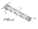
- FIG. 13 is another perspective view of the needle sheath of FIG. 12 but viewed from its closed end.
- the safety needle assembly 2 of the instant invention is shown to comprise four major components, namely a needle hub 4 , a collar 6 , a needle protection housing 8 attached to the collar 6 via a living hinge 10 , and a needle sheath 12 .
- needle hub 4 , collar 6 and needle sheath 12 are in alignment along a longitudinal axis 14 .
- the exposed components of the safety needle assembly of the instant invention are further shown in FIG. 2 to be in alignment with a conventional syringe 16 with a luer lock receptacle end that mates with needle hub 4 .
- An assembled safety needle assembly of the instant invention is shown in perspective view in FIG. 3 and in cross-sectional views in FIGS. 4 and 5 .
- needle hub 4 is shown to have a proximal portion 18 and a distal portion 20 .
- a needle 22 that fixedly extends from extension 24 of needle hub 4 is not shown in FIGS. 6 and 7 .
- proximal portion 18 and distal portion 20 of needle hub 4 do not have any actual line of demarcation, and are shown as such in FIGS. 4 , 6 and 7 solely for the convenience of the reader.
- needle hub 4 comprises a main body portion 26 that includes the base of needle hub 4 .
- a ring 28 circumferentially surrounds the proximal portion of needle hub 4 in spaced relationship to main body portion 26 .
- ring 28 is a part of needle hub 4 and is an integral part of main body portion 26 by means of a distal wall or partition 30 that extends transversely or orthogonally from main body portion 26 . From distal wall 30 the sidewall 32 of collar 28 extends to a proximal end 34 that has an opening 36 formed concentrically with opening or cavity 38 at luer end 40 of needle hub main body portion 26 .
- luer end 40 of needle hub 4 accordingly is threadingly matable with a corresponding luer connector such as that shown for syringe 16 in FIG. 2 .
- Ring 28 is also provided with two openings or windows 42 along its sidewall 32 to enable a user to view base portion 26 of needle hub 4 .
- needle hub 4 and the other components of the needle assembly, are made of conventional medical plastic such as polypropylene, or ABS plastic, and is substantially clear except for a color tinting as a way of color coding the assembly, the user can readily ascertain any flashing or blood, or blood flash, during a blood withdrawing procedure to thereby determine whether needle 22 has been correctly inserted into the vein of a patient.
- windows 42 a user can view the base portion, as well as luer end 40 of needle hub 4 .
- the safety needle assembly of the instant invention can also be used for infusion procedures.
- ring 28 The dimension of ring 28 is such that it enables the user to readily grasp needle hub 4 , and therefore the safety needle assembly as shown in FIG. 3 , for mating to syringe 16 as shown in FIG. 2 .
- luer end 40 of needle hub 4 may be coupled to the corresponding luer end 44 of syringe 16 by a rotational movement when syringe 16 has a luer lock type receptacle, as shown in FIG. 2 .
- the user upon grasping ring 28 , can simply insert luer 40 onto the luer slip receptacle of the syringe.
- flanges 44 in a coaxially circumferential manner a predetermine distance from end wall 30 of ring 28 .
- Flanges 44 each are chamfered or beveled at its front surface 46 , and extend circumferentially proximate to the front end of cavity 38 of the base portion 26 of needle hub 4 .
- cavity 38 of base portion 26 is connected to needle 22 by a through bore 50 at extension 24 .
- Extension 24 has a number of elongated ribs 56 , which has no bearing for this invention other than for cosmetic and manufacturing processes not related to the instant invention, as ribs 56 do not come into contact with needle sheath 12 at any time.
- flanges 44 With flanges 44 extending from base portion 26 a predetermined distance from end wall 30 , a space 52 is defined between flanges 44 and end wall 30 circumferentially about base portion 26 . As best shown in FIG. 6 , the back surfaces 54 of flanges 44 are formed at right angle to base portion 26 .
- needle hub 4 is in alignment with collar 6 and is coupled thereto per shown in the assembled views of FIGS. 3-5 .
- collar 6 is pivotally connected to needle protection housing 8 by living hinge 10 .
- housing 8 is pivotable in the direction indicated by directional arrow 56 , i.e., toward the longitudinal axis 14 for covering needle 22 .
- Collar 6 is cylindrical in shape and has a proximal portion or end 58 and a distal portion or end 60 . There are formed at the inner surface at proximal portion 58 of collar 6 a plurality of protrusions 62 which are substantially rectangularly shaped. Protrusions 62 each may have a chamfered surface 64 that faces needle hub 4 , as shown in the alignment of the components illustration of FIG. 1 . Moreover, protrusion 62 are dimensioned such that when collar 6 is press-fitted to needle hub 4 , they will matingly fit to space 52 defined by flanges 54 and end wall 30 at the distal portion of needle hub 4 .
- space 52 and protrusions 62 may be such that, although collar 6 is rotatable about base portion 26 of needle hub 4 , there nonetheless is enough friction between either one of flanges 44 , end wall 30 or the outer surface of needle hub base 26 and protrusions 62 to render collar 6 not freely rotatable about needle hub 4 , unless a predetermined torque or force is applied either to needle protection housing 8 , living hinge 10 or collar 6 , to rotate collar 6 relative to needle hub 4 .
- Voids 66 provided at proximal portion 58 of collar 6 enable proximal portion 58 to flex, or expand, when collar 6 is press-fitted to the distal portion of needle hub 4 , particularly when protrusions 62 come into contact with flanges 44 .
- the respective chamfered or beveled surfaces 46 and 64 of flanges 44 and protrusions 62 respectively, facilitate the insertion of collar 6 , and more particularly protrusions 62 into space 52 of needle hub 4 .
- Distal portion 60 of collar 6 has at its distal end, or proximate thereto, a rib 68 formed at the inner surface of collar 6 .
- rib 68 is divided into two halves, per notches 70 formed at opposed sides of distal portion 60 .
- Notches 70 provide additional flexibility to the distal portion of collar 6 when needle sheath 12 is fitted thereto. More on that later.
- rib 68 is formed to have either a semi-circular configuration or a configuration that is made up of a number of beveled surfaces for facilitating the mating of distal portion 60 of collar 6 with the proximal portion 74 of needle sheath 12 .
- the beveled surfaces of rib 68 are collectively designated 72 .
- Needle protection housing 8 is connected, by living hinge 10 , to collar 6 at the latter's proximal portion 58 .
- Needle protective housing 8 has an open proximal end 75 and a closed end 78 .
- Housing 8 is cylindrical in shape and has an opening 80 through which needle 22 passes, when housing 8 is pivoted toward collar 6 for covering needle 22 after needle sheath 12 has been removed from collar 6 .
- Opening or channel 80 is formed by two lips or flaps 82 and 84 each of which extends longitudinally along the entire length of housing 8 . Lip 82 overlaps lip 84 , with the overlapping being such that the combination of lips 82 and 84 providing a trap door for needle 22 .
- Opening 80 due to its formation by lips 82 and 84 , is off-centered to one side of housing 8 to enhance the entry of needle 22 into housing 8 .
- Each of lips 82 and 84 is angled, by a series of complex angles, as best shown in FIGS. 10 and 11 , toward the interior of housing 8 .
- the respective angles of each of the lips are therefore varied along the length of the housing for guiding needle 22 into housing 8 via opening 80 .
- the respective progressively angled surfaces of lips 82 and 84 are designated 86 and 88 , respectively.
- the angled entry of needle 22 into housing 8 is effected in a smooth manner to substantially eliminate the possibility that contaminated fluid that remains on needle 22 after its use may be flickered or splattered when needle 22 comes into contact with housing 8 .
- a lock mechanism is provided at the proximal end 75 of needle housing 8 and the outer surface of collar 6 . This ensures that once needle housing 8 is pivoted to the position along longitudinal axis 14 , it will remain in alignment thereat.
- This lock mechanism as shown in FIGS. 1-3 and 9 - 11 , comprises two apertures 76 at the base of needle housing 8 , and two corresponding one-way downward sloping catch members 74 at collar 6 .
- the apertures and catch members may be formed at collar 6 and the base of housing 8 , respectively. Further, instead of apertures, non-through openings that nonetheless mate to the catch members are also envisioned.
- aperture 76 will snap fit over the one-way catch members 74 , with the base surfaces 73 of the one-way catch members 74 acting against the top surfaces 77 at the base of apertures 76 to thereby fixedly retain needle housing 8 relative to collar 6 .
- needle sheath 12 has a first engage mechanism that engages to a second engage mechanism at collar 6 .
- needle sheath 12 is a cylindrical cap that has formed at its proximal portion 74 a circumferential groove or slot 90 .
- Groove 90 is configured to have a dimension, as defined by stop 92 and proximal portion 74 , to accept rib 68 of collar 6 .
- proximal portion 74 of needle sheath 12 has an opening 94 that allows needle sheath 12 to be placed or positioned over needle 22 and be press-fitted onto the distal end of collar 6 .
- a user would remove needle sheath 12 by applying a predetermined force longitudinally relative to collar 6 .
- needle 22 may be used.
- needle protective housing 8 is pivoted to be in substantial alignment along longitudinal axis 14 so that the contaminated needle 22 enters into housing 8 and is trapped inside housing 8 by the trapdoor formed by lips 82 and 84 .
- housing 8 is fixedly retained to collar 6 by the mating of apertures 76 at the base of the housing 8 to the one-way catch member 74 at the outer surface of collar 6 .
- needle hub 4 from the syringe 28 of needle hub 4 is grasped, and in the case of a luer lock coupling, rotated counter-clockwise to remove needle hub 4 from the syringe, such as 16 shown in FIG. 2 .
- the safety needle assembly could be properly disposed.
Abstract
Description
Claims (25)
Priority Applications (8)
| Application Number | Priority Date | Filing Date | Title |
|---|---|---|---|
| US10/665,514 US8251961B2 (en) | 2003-09-22 | 2003-09-22 | Safety needle assembly and method for making the same |
| US10/832,339 US8152761B2 (en) | 2003-09-22 | 2004-04-27 | Safety needle assembly |
| CA2539156A CA2539156C (en) | 2003-09-22 | 2004-09-21 | Safety needle assembly and method for making the same |
| PCT/US2004/030830 WO2005030290A2 (en) | 2003-09-22 | 2004-09-21 | Safety needle assembly and method for making the same |
| MXPA06003096A MXPA06003096A (en) | 2003-09-22 | 2004-09-21 | Safety needle assembly and method for making the same. |
| JP2006528095A JP4881734B2 (en) | 2003-09-22 | 2004-09-21 | Safety needle assembly and method of forming the safety needle assembly |
| EP04784632.4A EP1670528B1 (en) | 2003-09-22 | 2004-09-21 | Safety needle assembly and method for making the same |
| US13/413,103 US8608695B2 (en) | 2003-09-22 | 2012-03-06 | Safety needle assembly |
Applications Claiming Priority (1)
| Application Number | Priority Date | Filing Date | Title |
|---|---|---|---|
| US10/665,514 US8251961B2 (en) | 2003-09-22 | 2003-09-22 | Safety needle assembly and method for making the same |
Related Child Applications (1)
| Application Number | Title | Priority Date | Filing Date |
|---|---|---|---|
| US10/832,339 Continuation-In-Part US8152761B2 (en) | 2003-09-22 | 2004-04-27 | Safety needle assembly |
Publications (2)
| Publication Number | Publication Date |
|---|---|
| US20050065481A1 US20050065481A1 (en) | 2005-03-24 |
| US8251961B2 true US8251961B2 (en) | 2012-08-28 |
Family
ID=34312887
Family Applications (3)
| Application Number | Title | Priority Date | Filing Date |
|---|---|---|---|
| US10/665,514 Expired - Fee Related US8251961B2 (en) | 2003-09-22 | 2003-09-22 | Safety needle assembly and method for making the same |
| US10/832,339 Expired - Fee Related US8152761B2 (en) | 2003-09-22 | 2004-04-27 | Safety needle assembly |
| US13/413,103 Expired - Fee Related US8608695B2 (en) | 2003-09-22 | 2012-03-06 | Safety needle assembly |
Family Applications After (2)
| Application Number | Title | Priority Date | Filing Date |
|---|---|---|---|
| US10/832,339 Expired - Fee Related US8152761B2 (en) | 2003-09-22 | 2004-04-27 | Safety needle assembly |
| US13/413,103 Expired - Fee Related US8608695B2 (en) | 2003-09-22 | 2012-03-06 | Safety needle assembly |
Country Status (2)
| Country | Link |
|---|---|
| US (3) | US8251961B2 (en) |
| JP (1) | JP4881734B2 (en) |
Cited By (6)
| Publication number | Priority date | Publication date | Assignee | Title |
|---|---|---|---|---|
| US20130058751A1 (en) * | 2010-04-15 | 2013-03-07 | Mmi Ag | Micromanipulation system comprising a protective system for capillaries |
| US9867951B2 (en) | 2014-04-08 | 2018-01-16 | B. Braun Melsungen Ag | Hinged cap needle assemblies and related methods |
| US10029049B2 (en) | 2015-03-19 | 2018-07-24 | B. Braun Melsungen Ag | Hinged shield assemblies and related methods |
| US10537687B2 (en) | 2011-09-01 | 2020-01-21 | Sol-Millennium Medical Hk Limited | Needle protection device and safety needle assembly |
| US10639430B2 (en) | 2010-11-22 | 2020-05-05 | B. Braun Melsungen Ag | Hinged shield assemblies and related methods |
| WO2021050794A1 (en) * | 2019-09-13 | 2021-03-18 | Becton, Dickinson And Company | Hinged needle shield and needle assemblies |
Families Citing this family (37)
| Publication number | Priority date | Publication date | Assignee | Title |
|---|---|---|---|---|
| EP1401514B1 (en) * | 2001-05-22 | 2008-10-22 | Becton, Dickinson and Company | Needle shield assembly having hinged needle shield |
| US20050124944A1 (en) * | 2001-07-09 | 2005-06-09 | Hwang Charles G. | Needle shield assembly having hinged needle shield and flexible cannula lock |
| DE60226468D1 (en) * | 2001-07-27 | 2008-06-19 | Becton Dickinson Co | ARRANGEMENT WITH LUER CONNECTION |
| MXPA06007545A (en) * | 2004-01-07 | 2006-08-31 | Smiths Medical Asd Inc | Needle protection device with gauge specific color coding and method for manufacturing thereof. |
| US20050146081A1 (en) * | 2004-01-07 | 2005-07-07 | Maclean David | Needle protection device with gauge specific color coding and method for manufacturing thereof |
| US7780637B2 (en) * | 2006-11-06 | 2010-08-24 | Steven Jerde | Medical device container |
| US8038654B2 (en) * | 2007-02-26 | 2011-10-18 | Becton, Dickinson And Company | Syringe having a hinged needle shield |
| MX2009009508A (en) | 2007-03-07 | 2009-09-16 | Becton Dickinson Co | Safety blood collection assembly with indicator. |
| US8888713B2 (en) * | 2007-03-07 | 2014-11-18 | Becton, Dickinson And Company | Safety blood collection assembly with indicator |
| DE102008013198B4 (en) * | 2008-03-07 | 2011-07-14 | Bayer Schering Pharma Aktiengesellschaft, 13353 | Tamper evident closure with retaining pin |
| US8795198B2 (en) | 2008-03-07 | 2014-08-05 | Becton, Dickinson And Company | Flashback blood collection needle |
| US8603009B2 (en) | 2008-03-07 | 2013-12-10 | Becton, Dickinson And Company | Flashback blood collection needle |
| US20110066107A1 (en) * | 2008-05-14 | 2011-03-17 | John Stephens | Needle protective device |
| DE102009039572A1 (en) * | 2009-09-01 | 2011-03-03 | Schreiner Group Gmbh & Co. Kg | Label for attachment to a syringe body and syringe body |
| ES2710905T3 (en) | 2011-01-24 | 2019-04-29 | E3D Agricultural Coop Association Ltd | Injector |
| US20140012205A1 (en) * | 2011-03-23 | 2014-01-09 | Sanofi-Aventis Deutschland Gmbh | Drug Delivery Device with Pivoting Protective Cap |
| EP2545957A1 (en) | 2011-07-15 | 2013-01-16 | Becton Dickinson France | Drug delivery device and adaptor |
| EP2572742A1 (en) * | 2011-09-23 | 2013-03-27 | Sanofi-Aventis Deutschland GmbH | Needle safety device |
| SE1350137A1 (en) * | 2013-02-05 | 2014-08-06 | Vigmed Ab | needle device |
| GB201307385D0 (en) * | 2013-04-24 | 2013-06-05 | Star Syringe Ltd | Syringes |
| US9861784B2 (en) * | 2013-12-03 | 2018-01-09 | Becton, Dickinson And Company | Blood collection device with double pivot shields |
| CN105979991B (en) * | 2013-12-05 | 2020-03-03 | 梅捷医药有限公司 | Safety clamp |
| CN203790382U (en) * | 2014-03-13 | 2014-08-27 | 扬州美德莱国际贸易有限公司 | Disposable safety injection needle |
| KR102285178B1 (en) * | 2014-03-31 | 2021-08-02 | 니프로 가부시키가이샤 | Syringe, and safety device for syringe needle |
| GB2532979A (en) * | 2014-12-04 | 2016-06-08 | Owen Mumford Ltd | Needle assemblies |
| CN107427646B (en) * | 2015-03-27 | 2021-03-19 | 泰尔茂株式会社 | Injection needle assembly and drug injection device |
| CN106390238A (en) * | 2016-11-02 | 2017-02-15 | 扬州美德莱医疗用品有限公司 | Disposable safe insulin syringe |
| RU180561U1 (en) * | 2017-01-13 | 2018-06-18 | Рамазан Мусаевич Файзиев | Spring syringe with retractable needle, protected before and after injection |
| CN107126602B (en) * | 2017-06-02 | 2023-03-28 | 南京巨鲨显示科技有限公司 | Flange cover plate turnover device for fixing needle cylinder |
| TWI645874B (en) * | 2017-06-07 | 2019-01-01 | 魏慶祥 | Safety cover of injection needle and its base |
| WO2019053112A1 (en) * | 2017-09-14 | 2019-03-21 | Becton Dickinson France | Safety assembly |
| KR102071838B1 (en) * | 2018-02-13 | 2020-01-31 | 이남수 | Safety cap of injector with protection cover of sliding opening structure |
| WO2020241708A1 (en) * | 2019-05-27 | 2020-12-03 | ニプロ株式会社 | Protector-attached puncture needle |
| US11207469B1 (en) * | 2021-03-04 | 2021-12-28 | Expressions Design Studio, LLC | Low deadspace syringe including a pivoting needle guard |
| EP4329863A1 (en) * | 2021-04-25 | 2024-03-06 | Dental Products LAB, LLC | Needle safety sheath, guard, and device |
| KR102535927B1 (en) * | 2021-09-02 | 2023-05-26 | 최근욱 | Safety cover syringe to prevent stick injury and reuse |
| CN115054781A (en) * | 2022-05-26 | 2022-09-16 | 扬州美德莱医疗用品股份有限公司 | Connecting structure of safety needle shield and needle seat |
Citations (35)
| Publication number | Priority date | Publication date | Assignee | Title |
|---|---|---|---|---|
| US2693183A (en) * | 1951-10-10 | 1954-11-02 | Compule Corp | Hypodermic syringe blood telltale |
| US4664259A (en) | 1985-05-13 | 1987-05-12 | Robert Landis | Needle container and method for preventing accidental contact with a needle |
| US4982842A (en) | 1990-06-04 | 1991-01-08 | Concord/Portex | Safety needle container |
| US5037401A (en) | 1990-04-20 | 1991-08-06 | Decamp Dennis M | Hypodermic needle cannula guard |
| US5139489A (en) | 1991-01-07 | 1992-08-18 | Smiths Industries Medical Systems, Inc. | Needle protection device |
| US5188611A (en) | 1990-05-31 | 1993-02-23 | Orgain Peter A | Safety sheath for needles, sharp instruments and tools |
| US5232454A (en) | 1990-08-01 | 1993-08-03 | Smiths Industries Medical Systems, Inc. | Safety needle container |
| US5277311A (en) | 1991-12-20 | 1994-01-11 | Smiths Industries Medical Systems, Inc. | Needle assembly holder with rotatable safety sheath member and method of effecting proper alignment of a cannula using such needle assembly holder |
| US5445619A (en) * | 1994-09-23 | 1995-08-29 | Becton, Dickinson And Company | Shielded needle assembly |
| US5490841A (en) * | 1994-07-29 | 1996-02-13 | Landis; Robert M. | Safety sheath device |
| US5509907A (en) | 1996-03-17 | 1996-04-23 | Med-Safe Products, Inc. | Syringe needle guard assembly |
| US5584816A (en) | 1995-05-25 | 1996-12-17 | Becton, Dickinson And Company | Hardpack shield for a pivoting needle guard |
| US5599318A (en) | 1995-08-29 | 1997-02-04 | Becton, Dickinson And Company | Needle shield assembly having a releasable lock |
| US5599313A (en) | 1995-02-03 | 1997-02-04 | Becton, Dickinson And Company | Needle shield assembly having safety indication features |
| US5632732A (en) | 1996-09-11 | 1997-05-27 | Becton, Dickinson And Company | Needle assembly having single handedly activated shield |
| US5643219A (en) | 1994-09-23 | 1997-07-01 | Burns; James A. | Shielded needle assembly |
| US5662617A (en) | 1994-09-23 | 1997-09-02 | Becton, Dickinson And Company | Manually pivoted barrier assembly for piercing element |
| US5665075A (en) | 1996-07-03 | 1997-09-09 | Becton, Dickinson And Company | Method of making a needle shield assembly |
| US5669889A (en) * | 1996-07-03 | 1997-09-23 | Becton, Dickinson And Company | Needle shield assembly having a single-use lock |
| US5681295A (en) * | 1996-07-03 | 1997-10-28 | Becton, Dickinson And Company | Needle shield assembly having a single-use cannula lock |
| US5697908A (en) | 1996-09-26 | 1997-12-16 | Becton Dickinson France, S.A. | Lockable safety shield for a prefillable syringe |
| US5733265A (en) | 1996-09-25 | 1998-03-31 | Becton Dickinson And Company | Shielded needle assembly |
| US5868716A (en) | 1996-08-23 | 1999-02-09 | Becton, Dickinson And Company | Shielded needle assembly |
| US5913846A (en) | 1996-06-13 | 1999-06-22 | Becton, Dickinson And Company | Shielded needle assembly |
| US5919165A (en) | 1997-09-26 | 1999-07-06 | Becton, Dickinson And Company | Rotatable needle shield for needle cannula |
| US5993426A (en) | 1993-04-16 | 1999-11-30 | Sims Portex Inc. | Fluid absorbable needle sheath |
| USRE37110E1 (en) | 1992-05-18 | 2001-03-27 | William H. Hollister | Locking safety needle protection system |
| USRE37252E1 (en) | 1992-05-18 | 2001-07-03 | Sims Portex Inc. | Safety needle cartridge system |
| US6334857B1 (en) | 1999-01-11 | 2002-01-01 | Sims Portex Inc. | Needle protection apparatus used with a vial |
| US20020010433A1 (en) * | 2000-05-25 | 2002-01-24 | Johnson Johnnie M. | Adapter and method of attachment for "LUER LOK" receptacles |
| US6440104B1 (en) | 1998-08-28 | 2002-08-27 | Becton, Dickinson And Company | Safety shield assembly |
| US20020161336A1 (en) * | 1999-08-23 | 2002-10-31 | Becton, Dickinson And Company | Needle shield assembly |
| US6719737B2 (en) | 2002-05-13 | 2004-04-13 | Terumo Medical Corporation | Safety needle assembly |
| US7014622B1 (en) * | 1999-02-18 | 2006-03-21 | Medsafe Technologies, Llc | Interchangeable needle safety syringe |
| US7156825B2 (en) * | 2003-03-20 | 2007-01-02 | Smiths Medical Asd, Inc. | Safety adapter for needle hub assembly |
Family Cites Families (5)
| Publication number | Priority date | Publication date | Assignee | Title |
|---|---|---|---|---|
| US5407431A (en) * | 1989-07-11 | 1995-04-18 | Med-Design Inc. | Intravenous catheter insertion device with retractable needle |
| US5615771A (en) * | 1992-05-18 | 1997-04-01 | Smiths Industries Medical Systems, Inc. | Safety needle cartridge system |
| US6298541B1 (en) * | 1998-08-28 | 2001-10-09 | Becton, Dickinson And Company | Method for making a safety shield assembly and related combinations thereof |
| US6582397B2 (en) * | 2001-06-19 | 2003-06-24 | Portex, Inc. | Needle safety device with antiremoval protection |
| US6695819B2 (en) * | 2001-10-19 | 2004-02-24 | Terumo Medical Corporation | Safety needle assembly |
-
2003
- 2003-09-22 US US10/665,514 patent/US8251961B2/en not_active Expired - Fee Related
-
2004
- 2004-04-27 US US10/832,339 patent/US8152761B2/en not_active Expired - Fee Related
- 2004-09-21 JP JP2006528095A patent/JP4881734B2/en not_active Expired - Fee Related
-
2012
- 2012-03-06 US US13/413,103 patent/US8608695B2/en not_active Expired - Fee Related
Patent Citations (38)
| Publication number | Priority date | Publication date | Assignee | Title |
|---|---|---|---|---|
| US2693183A (en) * | 1951-10-10 | 1954-11-02 | Compule Corp | Hypodermic syringe blood telltale |
| US4664259A (en) | 1985-05-13 | 1987-05-12 | Robert Landis | Needle container and method for preventing accidental contact with a needle |
| US5037401A (en) | 1990-04-20 | 1991-08-06 | Decamp Dennis M | Hypodermic needle cannula guard |
| US5188611A (en) | 1990-05-31 | 1993-02-23 | Orgain Peter A | Safety sheath for needles, sharp instruments and tools |
| US4982842A (en) | 1990-06-04 | 1991-01-08 | Concord/Portex | Safety needle container |
| US5154285A (en) | 1990-08-01 | 1992-10-13 | Smiths Industries Medical Systems, Inc. | Needle assembly holder with rotatable safety sheath member |
| US5232454A (en) | 1990-08-01 | 1993-08-03 | Smiths Industries Medical Systems, Inc. | Safety needle container |
| US5139489A (en) | 1991-01-07 | 1992-08-18 | Smiths Industries Medical Systems, Inc. | Needle protection device |
| US5277311A (en) | 1991-12-20 | 1994-01-11 | Smiths Industries Medical Systems, Inc. | Needle assembly holder with rotatable safety sheath member and method of effecting proper alignment of a cannula using such needle assembly holder |
| USRE37252E1 (en) | 1992-05-18 | 2001-07-03 | Sims Portex Inc. | Safety needle cartridge system |
| USRE37110E1 (en) | 1992-05-18 | 2001-03-27 | William H. Hollister | Locking safety needle protection system |
| US5993426A (en) | 1993-04-16 | 1999-11-30 | Sims Portex Inc. | Fluid absorbable needle sheath |
| US6328713B1 (en) | 1993-04-16 | 2001-12-11 | Sims Portex Inc. | Needle sheath device |
| US5490841A (en) * | 1994-07-29 | 1996-02-13 | Landis; Robert M. | Safety sheath device |
| US5445619A (en) * | 1994-09-23 | 1995-08-29 | Becton, Dickinson And Company | Shielded needle assembly |
| US5891103A (en) | 1994-09-23 | 1999-04-06 | Becton Dickinson And Company | Shielded needle assembly |
| US5643219A (en) | 1994-09-23 | 1997-07-01 | Burns; James A. | Shielded needle assembly |
| US5662617A (en) | 1994-09-23 | 1997-09-02 | Becton, Dickinson And Company | Manually pivoted barrier assembly for piercing element |
| US5599313A (en) | 1995-02-03 | 1997-02-04 | Becton, Dickinson And Company | Needle shield assembly having safety indication features |
| US5584816A (en) | 1995-05-25 | 1996-12-17 | Becton, Dickinson And Company | Hardpack shield for a pivoting needle guard |
| US5599318A (en) | 1995-08-29 | 1997-02-04 | Becton, Dickinson And Company | Needle shield assembly having a releasable lock |
| US5509907A (en) | 1996-03-17 | 1996-04-23 | Med-Safe Products, Inc. | Syringe needle guard assembly |
| US5913846A (en) | 1996-06-13 | 1999-06-22 | Becton, Dickinson And Company | Shielded needle assembly |
| US5665075A (en) | 1996-07-03 | 1997-09-09 | Becton, Dickinson And Company | Method of making a needle shield assembly |
| US5681295A (en) * | 1996-07-03 | 1997-10-28 | Becton, Dickinson And Company | Needle shield assembly having a single-use cannula lock |
| US5669889A (en) * | 1996-07-03 | 1997-09-23 | Becton, Dickinson And Company | Needle shield assembly having a single-use lock |
| US5868716A (en) | 1996-08-23 | 1999-02-09 | Becton, Dickinson And Company | Shielded needle assembly |
| US5632732A (en) | 1996-09-11 | 1997-05-27 | Becton, Dickinson And Company | Needle assembly having single handedly activated shield |
| US5733265A (en) | 1996-09-25 | 1998-03-31 | Becton Dickinson And Company | Shielded needle assembly |
| US5697908A (en) | 1996-09-26 | 1997-12-16 | Becton Dickinson France, S.A. | Lockable safety shield for a prefillable syringe |
| US5919165A (en) | 1997-09-26 | 1999-07-06 | Becton, Dickinson And Company | Rotatable needle shield for needle cannula |
| US6440104B1 (en) | 1998-08-28 | 2002-08-27 | Becton, Dickinson And Company | Safety shield assembly |
| US6334857B1 (en) | 1999-01-11 | 2002-01-01 | Sims Portex Inc. | Needle protection apparatus used with a vial |
| US7014622B1 (en) * | 1999-02-18 | 2006-03-21 | Medsafe Technologies, Llc | Interchangeable needle safety syringe |
| US20020161336A1 (en) * | 1999-08-23 | 2002-10-31 | Becton, Dickinson And Company | Needle shield assembly |
| US20020010433A1 (en) * | 2000-05-25 | 2002-01-24 | Johnson Johnnie M. | Adapter and method of attachment for "LUER LOK" receptacles |
| US6719737B2 (en) | 2002-05-13 | 2004-04-13 | Terumo Medical Corporation | Safety needle assembly |
| US7156825B2 (en) * | 2003-03-20 | 2007-01-02 | Smiths Medical Asd, Inc. | Safety adapter for needle hub assembly |
Cited By (7)
| Publication number | Priority date | Publication date | Assignee | Title |
|---|---|---|---|---|
| US20130058751A1 (en) * | 2010-04-15 | 2013-03-07 | Mmi Ag | Micromanipulation system comprising a protective system for capillaries |
| US10639430B2 (en) | 2010-11-22 | 2020-05-05 | B. Braun Melsungen Ag | Hinged shield assemblies and related methods |
| US10537687B2 (en) | 2011-09-01 | 2020-01-21 | Sol-Millennium Medical Hk Limited | Needle protection device and safety needle assembly |
| US9867951B2 (en) | 2014-04-08 | 2018-01-16 | B. Braun Melsungen Ag | Hinged cap needle assemblies and related methods |
| US10029049B2 (en) | 2015-03-19 | 2018-07-24 | B. Braun Melsungen Ag | Hinged shield assemblies and related methods |
| US10617830B2 (en) | 2015-03-19 | 2020-04-14 | B. Braun Melsungen Ag | Hinged shield assemblies and related methods |
| WO2021050794A1 (en) * | 2019-09-13 | 2021-03-18 | Becton, Dickinson And Company | Hinged needle shield and needle assemblies |
Also Published As
| Publication number | Publication date |
|---|---|
| JP2007505722A (en) | 2007-03-15 |
| US20120172810A1 (en) | 2012-07-05 |
| US20050065481A1 (en) | 2005-03-24 |
| US8608695B2 (en) | 2013-12-17 |
| US20050065482A1 (en) | 2005-03-24 |
| US8152761B2 (en) | 2012-04-10 |
| JP4881734B2 (en) | 2012-02-22 |
Similar Documents
| Publication | Publication Date | Title |
|---|---|---|
| US8251961B2 (en) | Safety needle assembly and method for making the same | |
| US8029463B2 (en) | Needle protection assembly | |
| CA2609096C (en) | Safety needle device with snap feature and method of making same | |
| US8061007B2 (en) | Fixed needle syringe with protective needle housing | |
| CA2453162C (en) | Needle shield assembly having hinged needle shield and flexible cannula lock | |
| EP3002020B1 (en) | Needle shield aasembly | |
| CA2593252C (en) | Safety needle device with snap feature | |
| CA2449324C (en) | Hinged needle shield assembly having needle cannula lock | |
| EP1648539A1 (en) | Medicament container with needle protection housing | |
| US20160220766A1 (en) | Safety needle assembly | |
| JP7286681B2 (en) | cap for injection device | |
| EP3270990B1 (en) | Hinged shield assemblies and related methods | |
| CA2579842C (en) | Safety adapter for needle hub assembly | |
| EP1670528B1 (en) | Safety needle assembly and method for making the same | |
| US20040186438A1 (en) | Safety adapter for needle hub assembly |
Legal Events
| Date | Code | Title | Description |
|---|---|---|---|
| AS | Assignment |
Owner name: PORTEX, INC., NEW HAMPSHIRE Free format text: ASSIGNMENT OF ASSIGNORS INTEREST;ASSIGNORS:HAURI, MARIUS;BLINKHORN, FRANK;MACLEAN, DAVID;AND OTHERS;REEL/FRAME:014550/0260;SIGNING DATES FROM 20030915 TO 20030918 Owner name: PORTEX, INC., NEW HAMPSHIRE Free format text: ASSIGNMENT OF ASSIGNORS INTEREST;ASSIGNORS:HAURI, MARIUS;BLINKHORN, FRANK;MACLEAN, DAVID;AND OTHERS;SIGNING DATES FROM 20030915 TO 20030918;REEL/FRAME:014550/0260 |
|
| AS | Assignment |
Owner name: SMITHS MEDICAL ASD, INC., NEW HAMPSHIRE Free format text: CHANGE OF NAME;ASSIGNOR:PORTEX, INC.;REEL/FRAME:015035/0711 Effective date: 20031103 Owner name: SMITHS MEDICAL ASD, INC.,NEW HAMPSHIRE Free format text: CHANGE OF NAME;ASSIGNOR:PORTEX, INC.;REEL/FRAME:015035/0711 Effective date: 20031103 |
|
| STCF | Information on status: patent grant |
Free format text: PATENTED CASE |
|
| FPAY | Fee payment |
Year of fee payment: 4 |
|
| FEPP | Fee payment procedure |
Free format text: MAINTENANCE FEE REMINDER MAILED (ORIGINAL EVENT CODE: REM.); ENTITY STATUS OF PATENT OWNER: LARGE ENTITY |
|
| LAPS | Lapse for failure to pay maintenance fees |
Free format text: PATENT EXPIRED FOR FAILURE TO PAY MAINTENANCE FEES (ORIGINAL EVENT CODE: EXP.); ENTITY STATUS OF PATENT OWNER: LARGE ENTITY |
|
| STCH | Information on status: patent discontinuation |
Free format text: PATENT EXPIRED DUE TO NONPAYMENT OF MAINTENANCE FEES UNDER 37 CFR 1.362 |
|
| FP | Lapsed due to failure to pay maintenance fee |
Effective date: 20200828 |