US8252464B2 - Method of making a battery grid - Google Patents
Method of making a battery grid Download PDFInfo
- Publication number
- US8252464B2 US8252464B2 US13/290,789 US201113290789A US8252464B2 US 8252464 B2 US8252464 B2 US 8252464B2 US 201113290789 A US201113290789 A US 201113290789A US 8252464 B2 US8252464 B2 US 8252464B2
- Authority
- US
- United States
- Prior art keywords
- grid
- wires
- battery
- wire
- deforming
- Prior art date
- Legal status (The legal status is an assumption and is not a legal conclusion. Google has not performed a legal analysis and makes no representation as to the accuracy of the status listed.)
- Expired - Fee Related
Links
Images


Classifications
-
- H—ELECTRICITY
- H01—ELECTRIC ELEMENTS
- H01M—PROCESSES OR MEANS, e.g. BATTERIES, FOR THE DIRECT CONVERSION OF CHEMICAL ENERGY INTO ELECTRICAL ENERGY
- H01M4/00—Electrodes
- H01M4/02—Electrodes composed of, or comprising, active material
- H01M4/64—Carriers or collectors
- H01M4/70—Carriers or collectors characterised by shape or form
- H01M4/72—Grids
- H01M4/73—Grids for lead-acid accumulators, e.g. frame plates
-
- H—ELECTRICITY
- H01—ELECTRIC ELEMENTS
- H01M—PROCESSES OR MEANS, e.g. BATTERIES, FOR THE DIRECT CONVERSION OF CHEMICAL ENERGY INTO ELECTRICAL ENERGY
- H01M4/00—Electrodes
- H01M4/02—Electrodes composed of, or comprising, active material
- H01M4/64—Carriers or collectors
- H01M4/70—Carriers or collectors characterised by shape or form
- H01M4/72—Grids
- H01M4/74—Meshes or woven material; Expanded metal
- H01M4/745—Expanded metal
-
- H—ELECTRICITY
- H01—ELECTRIC ELEMENTS
- H01M—PROCESSES OR MEANS, e.g. BATTERIES, FOR THE DIRECT CONVERSION OF CHEMICAL ENERGY INTO ELECTRICAL ENERGY
- H01M4/00—Electrodes
- H01M4/02—Electrodes composed of, or comprising, active material
- H01M4/64—Carriers or collectors
- H01M4/82—Multi-step processes for manufacturing carriers for lead-acid accumulators
- H01M4/84—Multi-step processes for manufacturing carriers for lead-acid accumulators involving casting
-
- Y—GENERAL TAGGING OF NEW TECHNOLOGICAL DEVELOPMENTS; GENERAL TAGGING OF CROSS-SECTIONAL TECHNOLOGIES SPANNING OVER SEVERAL SECTIONS OF THE IPC; TECHNICAL SUBJECTS COVERED BY FORMER USPC CROSS-REFERENCE ART COLLECTIONS [XRACs] AND DIGESTS
- Y02—TECHNOLOGIES OR APPLICATIONS FOR MITIGATION OR ADAPTATION AGAINST CLIMATE CHANGE
- Y02E—REDUCTION OF GREENHOUSE GAS [GHG] EMISSIONS, RELATED TO ENERGY GENERATION, TRANSMISSION OR DISTRIBUTION
- Y02E60/00—Enabling technologies; Technologies with a potential or indirect contribution to GHG emissions mitigation
- Y02E60/10—Energy storage using batteries
-
- Y—GENERAL TAGGING OF NEW TECHNOLOGICAL DEVELOPMENTS; GENERAL TAGGING OF CROSS-SECTIONAL TECHNOLOGIES SPANNING OVER SEVERAL SECTIONS OF THE IPC; TECHNICAL SUBJECTS COVERED BY FORMER USPC CROSS-REFERENCE ART COLLECTIONS [XRACs] AND DIGESTS
- Y02—TECHNOLOGIES OR APPLICATIONS FOR MITIGATION OR ADAPTATION AGAINST CLIMATE CHANGE
- Y02P—CLIMATE CHANGE MITIGATION TECHNOLOGIES IN THE PRODUCTION OR PROCESSING OF GOODS
- Y02P70/00—Climate change mitigation technologies in the production process for final industrial or consumer products
- Y02P70/50—Manufacturing or production processes characterised by the final manufactured product
-
- Y—GENERAL TAGGING OF NEW TECHNOLOGICAL DEVELOPMENTS; GENERAL TAGGING OF CROSS-SECTIONAL TECHNOLOGIES SPANNING OVER SEVERAL SECTIONS OF THE IPC; TECHNICAL SUBJECTS COVERED BY FORMER USPC CROSS-REFERENCE ART COLLECTIONS [XRACs] AND DIGESTS
- Y10—TECHNICAL SUBJECTS COVERED BY FORMER USPC
- Y10T—TECHNICAL SUBJECTS COVERED BY FORMER US CLASSIFICATION
- Y10T29/00—Metal working
- Y10T29/10—Battery-grid making
-
- Y—GENERAL TAGGING OF NEW TECHNOLOGICAL DEVELOPMENTS; GENERAL TAGGING OF CROSS-SECTIONAL TECHNOLOGIES SPANNING OVER SEVERAL SECTIONS OF THE IPC; TECHNICAL SUBJECTS COVERED BY FORMER USPC CROSS-REFERENCE ART COLLECTIONS [XRACs] AND DIGESTS
- Y10—TECHNICAL SUBJECTS COVERED BY FORMER USPC
- Y10T—TECHNICAL SUBJECTS COVERED BY FORMER US CLASSIFICATION
- Y10T29/00—Metal working
- Y10T29/49—Method of mechanical manufacture
- Y10T29/49002—Electrical device making
- Y10T29/49108—Electric battery cell making
Definitions
- the present invention relates to the modification of battery grids of the type used in lead-acid storage batteries, and more particularly, it relates to a modification of the shape and/or surface finish of the battery grids of a lead-acid storage battery to improve paste adhesion and the service life of the battery.
- Lead-acid storage batteries typically comprise several cell elements which are encased in separate compartments of a container containing sulfuric acid electrolyte. Each cell element includes are least one positive plate, at least one negative plate, and a porous separator positioned between each positive and negative plate.
- the positive and negative plates each comprise a lead or lead alloy grid that supports an electrochemically active material.
- the active material is a lead based material (i.e., PbO, PbO 2 , Ph or PbSO 4 at different charge/discharge stages of the battery) that is pasted onto the grid.
- the grids provide an electrical contact between the positive and negative active materials which serves to conduct current.
- the active material of a lead-acid battery may be prepared by mixing lead oxide, sulfuric acid and water. Dry additives, such as fiber and expander, may also be added.
- the active material paste is then applied to the lead grid.
- the pasted plates are next typically cured for many hours under elevated temperature and humidity to oxidize free lead (if any) and adjust the crystal structure of the plate. After curing, the plates are assembled into batteries and electrochemically formed by passage of current to convert the lead sulfate or basic lead sulfate(s) to lead dioxide (positive plates) or lead (negative plates). This is referred to as the “formation” process.
- the formation efficiency of lead-acid batteries depends to a great extent on the positive plate, in particular, to the extent of conversion of lead monoxide (PbO) to lead dioxide (PbO 2 ) in the active positive material.
- the high electrical potential required for formation appears to be related to the transformation of non-conductive paste materials to PbO 2 .
- a low formation efficiency of positive plates requires a high formation charge. Inefficient charging also leads to deficiencies in the resulting batteries assembled with such plates.
- the initial capacity (performance) of the battery is low if the battery is not completely formed, requiring additional cycling to reach specific performance values.
- U.S. Pat. No. 3,933,524 discloses a method of increasing the cycle life of a battery wherein antimony is deposited on a lead alloy grid in order to promote adhesion of the active materials to the grid. It is stated that the antimony may be deposited in a number of ways including electroplating, spraying, vapor deposition, sputtering and chemical displacement.
- a lead-calcium alloy substrate is coated with a layer of a tin, lead-antimony, lead-silver or lead-tin alloy.
- the layer of metal on the surface of the grid promotes better adhesion of the active material paste to the grid.
- the adhesion between a battery grid and battery active material may affect, among other things, battery formation processes and battery service life. Accordingly, various methods, such as those mentioned above, have been proposed to improve the adhesion between a battery grid and battery active material.
- each of these processes requires the incorporation of an additional material into the grid manufacturing process.
- the grid must be treated with an additional chemical (e.g., a persulfate or perborate solution, or an oxide).
- an additional layer of a dissimilar metal or alloy must be deposited on the grid by chemical (e.g., electroplating) or mechanical (e.g., roll-bonding) means. It can be appreciated that the additional process steps and materials required in these methods can significantly increase the cost of manufacturing the battery grids. As a result, certain battery manufacturers may be reluctant to incorporate these methods into a production facility.
- grids for lead acid batteries provide structural support for the active material therein, and serve as a current collector during discharge and a current distributor during recharge.
- Known arts of lead acid battery grid, making include: (1) batch processes such as book mold gravity casting; and (2) continuous processes such as strip expansion, strip stamping, continuous casting, and continuous casting followed by rolling. Grids made from these processes have unique features characteristic of the process and behave differently in lead acid batteries, especially with respect to the pasting process.
- molten lead is poured into a grid mold and cooled to form a grid.
- the surface of the grid made from book mold casting is somewhat rough and the geometric, shape of the cross-section of the grid wires is usually oval with a sharp angle formed at the plane where the book mold closes.
- Book mold casting is a batch process and its productivity is much lower than other processes that are continuous in nature.
- a cast or wrought lead strip is pierced, stretched above and below the strip plane, and then pulled or expanded to form a grid with a diamond pattern.
- the surface of the wires perpendicular to the plane of the strip is smooth and the cross-section of the wires is rectangular.
- Stamped grids also have smooth surfaces and a rectangular cross-section in the wires.
- the surface of the grid can be rough on the mold side and is smooth on the belt/air side.
- the geometry of the cross-section of the wires produced by continuous casting can be a triangle, a trapezoid, a section of an arc or a semi-circle, depending on the mold design. If the grids are rolled after casting, the surfaces become smooth and the cross-section of the grid wires become rectangular.
- an oval-shaped wire such as that in a book mold cast grid
- the rough surface and the sharp angle of the wires provide a mechanical graft and interlock of paste particles. Therefore, the contact between the grid and the battery paste is good and the plate is strong.
- rectangular wires on the other hand, it is much more difficult to make good contact between the battery paste and the surface of the wire moving in a direction perpendicular to the direction in which the paste is applied because the flow of paste must change in a 90 degree step. This is analogous to the situation where water flows down a 90 degree cliff, and the surface right below the edge of the cliff is not contacted by the falling water.
- the change of paste flow is gradual and continuous and therefore, provides better paste coverage.
- the battery paste When the battery paste is cured and dried, it will shrink and generate tensile force at the paste/grid interface.
- the tensile force at the paste/grid wire interface is at a maximum when the wire surface is perpendicular to the grid surface and at a minimum when the wire surface is parallel to the grid surface.
- a gap is formed between the grid wire and the paste at the location where the tensile force is the maximum.
- This type of plate is weak and the paste will fall off easily. Because of a lack of contact between the paste and the grid, a battery made with this type of plate is much more difficult to form, performs poorly in certain reserve capacity tests, and does not exhibit satisfactory cycle life.
- a method of forming battery grids or battery plates that includes the step of mechanically reshaping or refinishing battery grid wires to improve contact between the battery paste and the grid wires.
- paste adhesion is increased thereby increasing battery formation efficiency and battery cycle life.
- a battery grid is formed by a method that includes the steps of forming a preform battery grid and then reshaping or refinishing the grid wires of the preform battery grid to form a finished grid.
- the preform battery grid includes a grid network bordered by a frame element on at least one side.
- the top frame element has a current collector lug.
- the grid network comprises a plurality of spaced apart grid wire elements with opposed ends. Each of the opposed ends of each grid wire is joined to one of a plurality of nodes to define open spaces in the grid network.
- the reshaping or refinishing step at least a portion of the grid wire elements of the preform battery grid are deformed at a position between the opposed ends of the grid wire element.
- a first transverse cross-section taken at a position intermediate between the opposed ends of the grid wire element differs from a second transverse cross-section taken at one of the opposed ends of the grid wire element.
- This version of the invention is particularly useful in improving the paste adhesion to individual battery grids formed by a continuous process (such as strip expansion, strip stamping, continuous casting) that produces grid wires and nodes with smooth surfaces and a rectangular cross-section.
- individual grids formed by stamping process will typically have grid wires and nodes with smooth surfaces and a generally rectangular cross-section.
- the grid wires of the battery grids produced by the stamping process are deformed such that the grid wires have a cross-section other than the rectangular cross-section produced by the stamping process.
- the nodes and the opposed ends of each grid wire that are attached to each node retain a generally rectangular cross-section so that the grid surface retains a planar configuration.
- each of the interconnected battery grids includes a grid network bordered by a frame element on at least one side.
- the top frame element has a current collector lug.
- the grid network comprises a plurality of spaced apart grid wire elements with opposed ends.
- each of the opposed ends of each grid wire is joined to one of a plurality of nodes to define open spaces in the grid network.
- the reshaping or refinishing step at least a portion of the grid wire elements of the interconnected battery grids are deformed at a position between the opposed ends of the grid wire element.
- the strip of interconnected battery grids may be formed from a grid material by any of a number of methods including: (1) a stamping process wherein a continuous strip of grid material is fed along a path and grid material is punched out of the strip to form the strip of interconnected battery grids; (2) a continuous casting process wherein a grid material is melted and continuously cast to form the strip of interconnected battery grids; or (3) a strip expansion process wherein a continuous strip of grid material is fed along a linear path, apertures are pierced in the strip of grid material, and the strip is laterally expanded to form the strip of interconnected battery grids.
- the grid wires may be reshaped or refinished in a variety of manners.
- the grid wires are deformed by a stamping die at a position between the opposed ends of the grid wire element.
- the present invention also relates to a battery grid formed using the method of the present invention.
- the improved battery grid has a grid network bordered by a frame element on at least one side.
- the top frame element has a current collector lug.
- the grid network comprises a plurality of spaced apart grid wire elements, wherein each grid wire element has opposed ends and each of the opposed ends is joined to one of a plurality of nodes to define a plurality of open spaces. At least a portion of the grid wire elements have a first transverse cross-section taken at a position between the opposed ends of the grid wire element that differs from a second transverse cross-section taken at one of the opposed ends of the grid wire element.
- the intermediate portion of the grid wire has a shape different from the shape of the opposed ends of the grid wire where the grid wire and node meet.
- the cross-section of the intermediate portion of the grid wire may be any number of shapes including diamond, rhomboid, hexagon, octagon or oval.
- the intermediate portion of the grid wire elements may have a cross-section that is rotated about 20 to about 70 degrees in relation to the cross-section of the opposed ends of the grid wire where the grid wire and node meet. In this version of the invention, it is preferred that a major portion of the intermediate portion of the grid wire elements be rotated about 20 to about 70 degrees.
- FIG. 1 shows a front view of a battery grid made in accordance with one version of the method of the present invention
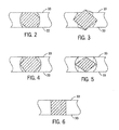
- FIG. 2 shows a cross-section of a vertical grid wire section taken along line 2 - 2 of FIG. 1 ;
- FIG. 3 shows a cross-section of a vertical grid wire section taken along line 3 - 3 of FIG.
- FIG. 4 shows a cross-section of a vertical grid wire section taken along line 4 - 4 of FIG. 1 ;
- FIG. 5 shows a cross-section of a vertical grid wire section taken along line 5 - 5 of FIG. 1 ;
- FIG. 6 shows a cross-section of a vertical rid wire section taken along line 6 - 6 of FIG. 1 ;
- FIG. 7 is a photomicrograph of a transverse cross-section of a battery plate prepared using a conventional stamped battery grid
- FIG. 8 is a photomicrograph of a transverse cross-section of a battery plate prepared using one version of a battery grid made in accordance with the present invention.
- FIG. 9 is a photomicrograph of a transverse cross-section of a battery plate prepared using another version of a battery grid made in accordance with the present invention.
- FIG. 10 is a photomicrograph of a transverse cross-section of a battery plate prepared using yet another version of a battery grid made in accordance with the present invention.
- FIG. 11 is a photomicrograph that shows a front view of a battery grid made in accordance with the method of the present invention.
- FIG. 12 is a photomicrograph that shows another front view of a battery grid made in accordance with the method of the present invention.
- FIG. 13 is a photomicrograph that shows another front view of a battery grid made in accordance with the method of the present invention.
- FIG. 14 is a photomicrograph that shows another front view of a battery grid made in accordance with the method of the present invention.
- FIG. 1 shows a front view of a battery grid made in accordance with one version of the method of the present invention.
- the grid is a stamped grid made of a lead alloy, and functions in the same manner as other battery grids known in the art. It should be noted that an infinite number of grid designs may result from the present invention and therefore, it is not the intent of the following description to limit the invention to the grid design shown in FIG. 1 , which is presented for the purposes of illustration.
- the grid 10 comprises a frame that includes a top frame element 12 , first and second side frame elements 14 and 16 , and a bottom frame element 18 .
- the grid 10 includes a series of grid wires that define open areas 20 that hold the electrochemical paste (not shown) that provides the current generation.
- a current collection lug 22 is integral with the top frame element 12 and is offset from the center of the top frame element 12 .
- the top frame element 12 includes an enlarged conductive section 24 directly beneath the lug 22 , and has the shape shown to optimize current conduction to the lug 22 .
- a series of radially extending vertical grid wire elements 26 ( a )- 26 ( o ) form part of the grid 10 .
- the vertical wire elements 26 ( c )- 26 ( n ) are connected to the top frame element 12 and the bottom frame element 18
- the vertical wire elements 26 ( a )- 26 ( b ) are connected to the top frame element 12 in the first side frame element 14
- the vertical wire element 26 ( o ) is connected to the top frame element 12 and the side frame element 16 , as shown.
- the vertical wire element 26 ( i ) is parallel to the side elements 14 and 16 , and the remaining vertical wire elements 26 ( a )- 26 ( h ) and 26 ( j )- 26 ( o ) extend radially toward an imaginary intersecting point along a radius line running through the vertical element 26 ( i ).
- the vertical wire elements 26 ( a )- 26 ( o ) become closer together when moving from the bottom element 18 towards the top element 12 and get farther apart when moving towards the left element 14 or the right element 16 from the vertical element 26 ( i ).
- the grid 10 also includes a plurality of horizontal or cross wire elements.
- the cross wire elements include a set of parallel horizontal wire elements 30 positioned in a middle portion of the grid 10 .
- the grid 10 includes a first set of cross wire elements 32 connected between the left frame element 14 and the vertical element 26 ( a ) that are parallel to each other, a second set of cross wire elements 34 connected between the vertical elements 26 ( a ) and 26 ( b ) that are parallel to each other, and a third set of cross wire elements connected between the vertical elements 26 ( b ) and 26 ( c ) that are parallel to each other at the left side of the grid 10 .
- the grid 10 includes a fourth set of cross wire elements 38 connected between the vertical elements 26 ( n ) and 26 ( o ) that are parallel to each other and a fifth set of cross wire elements 40 connected between the vertical element 26 ( o ) and the right frame element 16 that are parallel to each other at the right side of the grid, as shown.
- a series of short support wires 42 are connected to the bottom frame member 18 as shown.
- Individual sections of the vertical wire elements 26 ( a )- 26 ( o ) and the horizontal wire elements 30 or the cross wire elements 32 - 40 have opposed ends 43 which are joined at a plurality of nodes 44 that define the open areas 20 that support the electrochemical paste for conduction.
- each grid wire section may have a different cross-sectional configuration, or each grid wire section may have the same cross-sectional configuration. However, it is preferred that each grid wire section have the same cross-sectional configuration. It is also important to note that although certain features of the invention have been illustrated in FIGS. 2-5 by way of cross-sectional views of vertical grid wires, the same cross-sectional views could apply when taking a cross-section of horizontal grid wires. In other words, the similar deformation methods as illustrated in FIGS. 2 to 5 can also be applied, to the horizontal wire elements. Depending on the needs, a grid can be deformed at the vertical wire elements only, or at both the vertical and horizontal wire elements.
- FIG. 2 shows a cross-section of a section of vertical wire element 26 ( h ) taken at a position between the opposed ends of the grid wire section. It can be seen that at the position between the opposed ends of this grid wire section, the cross-section of the grid wire is substantially an octagon, while the cross section of the node and the end of the grid wire section (which are shown in phantom) are substantially rectangular. It can be appreciated by those in the art that a battery grid wire section or node will not have a perfect geometric configuration and that the rounding of edges and corners of a grid wire section or node is often the result of a manufacturing operation. For this reason, the description of cross-sectional shapes in the specification will be proceeded by the word “substantially” to indicate that the cross-sectional shape may vary somewhat from a perfect geometric shape.
- FIG. 3 shows a cross-section of a section of vertical wire element 26 ( i ) taken at a position between the opposed ends of the grid wire section. It can be seen that at the position between the opposed ends of this grid wire section, the cross-section of the grid wire has been rotated 45 degrees in relation to the node and the end of the grid wire section (shown in phantom), which have a substantially rectangular cross-section.
- FIG. 4 shows a cross-section of a section of vertical wire element 26 ( j ) taken at a position between the opposed ends of the grid wire section. It can be seen that at the position between the opposed ends of this grid wire section, the cross-section of the grid wire is substantially a hexagon, while the cross section of the node and the end of the grid wire section (which are shown in phantom) are substantially rectangular.
- FIG. 5 shows a cross-section of a section of vertical wire element 26 ( k ) taken at a position between the opposed ends of the grid wire section. It can be seen that at the position between the opposed ends of this grid wire section, the cross-section of the grid wire is substantially a diamond, while the cross section of the node and the end of the grid wire section (shown in phantom) are substantially rectangular.
- FIG. 6 shows a cross-section of a section of vertical wire element 26 ( l ) taken at a position between the opposed ends of the grid wire section.
- This figure shows the configuration of a conventional stamped battery grid wherein the cross section of the node and the cross-section at all positions along the grid wire section are substantially rectangular and the surfaces of the node and grid wire section are smooth.
- each grid wire does not extend above or below opposed flat planar surfaces 33 of the grid.
- the rotated cross-section of the grid wire does extend above and below the planar surfaces 33 of the grid because of the nature of the forming process used to deform the grid wire.
- the opposed planar surfaces 33 of the grid are formed by the grid network and the frames, and may vary slightly from a geometric flat planar surface due or manufacturing variability.
- the grid shown in FIGS. 1-5 may be manufactured by any of a number of versions of the method of the present invention.
- the battery grid is produced as part of an automated battery plate making process that includes grid stamping operations.
- a conventional lead or lead alloy battery grid material such as a lead-calcium-tin alloy
- the continuous strip may then be rolled to modify the thickness or grain structure of the strip.
- a series of interconnected battery grids is then formed by punching grid material out of the continuous strip.
- each of the interconnected battery grids has a grid network bordered by a frame as shown in FIG. 1 and described above.
- the battery grid wire sections of the strip are processed in a stamping station.
- the stamping station is used to deform or coin the grid wires so that the grid wires have a cross-section similar to one of the grid wire cross-sections shown in FIGS. 2-5 .
- the stamping station may include a die that deforms the rectangular cross-section of the grid wires of the punched grid into an octagonal cross-section as shown in FIG. 2 .
- a stamping die may be used that rotates the intermediate portion of the grid wire elements about 20 to about 70 degrees in relation to the cross-section of the opposed ends of the grid wire where the grid wire and node meet as depicted in FIG. 3 .
- modified grid wire shapes can be selected as long as the shape provides paste adhesion characteristics that are superior to the rectangular cross-section produced by a stamping process.
- the modified grid wire substantially has a diamond shape, a rhomboid shape, a hexagon shape, an octagon shape, or an oval shape.
- the area of deformation along the length of the grid wire between the opposed ends of each grid wire section may vary. For example, it is preferred that 90% of the length of the grid wire between the opposed ends of the grid wire undergo deformation at the stamping station. Using FIG.
- the interconnected grids having modified grid wires are then processed to apply battery paste and the strip is cut to form a plurality of battery plates.
- the interconnected grids may be cut into a plurality of grids before pasting and stored for later use.
- the interconnected battery grids may be formed by alternate means, such as strip expansion or continuous casting processes.
- strip expansion a continuous strip of grid material is fed along a linear path aligned with the longitudinal direction of the strip, apertures are punched in the strip of grid material, and the strip is laterally expanded to form the strip of interconnected battery grids.
- the grid material is melted and continuously cast to form the strip of interconnected battery grids.
- the continuous cast strip may be rolled to achieve dimensional control or grain structure modification.
- FIGS. 11-14 show a battery grid that was formed using the version of the method of the present invention wherein the grid openings are continuously punched out of a lead alloy strip and the grid wires are subjected to a coining deformation step in a stamping station. It can be seen that the areas where the opposed ends of the grid wire sections meet the nodes were not subjected to deformation and therefore, the areas retain the shape formed in the continuous punching operation. It can also be seen that the areas of the grid openings near the nodes have a slight inner radius that results from the process.
- a conventional stamped battery grid with grid wires having a rectangular cross-section and smooth surfaces (as depicted in FIGS. 1 and 6 ) was pasted with a conventional positive paste for lead acid batteries and then cured.
- the cured plate was sectioned with a cutting wheel in a direction transverse to the planar surface of the plate, polished, and photographed. The photograph is shown in FIG. 7 .
- the cured plate exhibits gaps 70 at the paste 72 /grid wire 73 interfaces, and the gaps extend into the bulk paste as cracks 71 .
- a second conventional stamped battery grid identical to the grid used in Example 1 was substantially modified by rotating a major portion of grid wires by 45 degrees. (This version of a grid is depicted in FIGS. 1 and 3 .)
- the modified grid was then pasted with a conventional positive paste for lead acid batteries and cured.
- the cured plate was sectioned with a cutting wheel in a direction transverse to the planar surface of the plate, polished, and photographed.
- the photograph is shown in FIG. 8 wherein the grid wire is designated at 80 and the paste is designated at 81 . It can be seen from FIG. 8 that the plate prepared using the modified grid of Example 1(a) exhibited improved paste adhesion compared to the plate prepared using the grid of Example 1 ( FIG. 7 ) and that the plate prepared using the modified grid of Example 1(a) exhibited a reduced number of cracks.
- a third conventional stamped battery grid identical to the grid used in Example 1 was substantially modified by stamping the grid wires to form a diamond-shaped cross-section, (This version of a grid is depicted in FIGS. 1 and 5 .)
- the modified grid was then pasted with a conventional positive paste for lead acid batteries and cured.
- the cured plate was sectioned with a cutting wheel in a direction transverse to the surface of the plate, polished, and photographed. The photograph is shown in FIG. 9 . It can be seen from FIG. 9 (Wherein the grid wire is designated at 90 and the paste is designated at 91 ) that the plate prepared using the modified grid of Example 1(b) exhibited improved paste adhesion compared to the plate prepared using the grid of Example 1 ( FIG. 7 ) and that the plate prepared using the modified grid of Example 1(b) exhibited a reduced number of cracks.
- a fourth conventional stamped battery grid identical to the grid used in Example 1 was substantially modified by stamping the grid wires to form an octagonal shaped cross-section.
- This version of a grid is depicted in FIGS. 1 and 2 .
- the modified grid was then pasted with a conventional positive paste for lead acid batteries and cured.
- the cured plate was sectioned with a cutting wheel in a direction transverse to the surface of the plate, polished, and photographed. The photograph is shown in FIG. 10 . It can be seen from FIG. 10 (wherein the grid wire is designated at 100 and the paste is designated at 101 ) that the plate prepared using the modified grid of Example 1(c) exhibited improved paste adhesion compared to the plate prepared using the grid of Example 1 ( FIG. 7 ) and that the plate prepared using the modified grid of Example 1(c) exhibited a reduced number of cracks.
- Vibration weight loss is a very good measure to evaluate the strength of a battery plate.
- two battery plates were prepared.
- the first battery plate was prepared using the procedure of Example 1, and the second battery plate was prepared using the procedure of Example 1(c).
- the control plate of Example 1 and the plate of the present invention as described as Example 1(c) were then placed on a platform vibrating at a frequency of about 60 hertz with an amplitude of about three millimeters for one minute.
- the plate weights before and after vibration were compared.
- the control plates of Example 1 lost 16 times the battery paste that was lost in plates formed in accordance with the present invention of Example 1(c). This test demonstrated that when assembled into battery plates, battery grids manufactured in accordance with the present invention improve paste adhesion between the grid and the paste.
- Batteries made of conventional stamped grids and grids prepared in accordance with the present invention as described in Example 1(c) were cycled in accordance with the SAE J240 life test procedure at a temperature of 167° F. to measure the service life.
- Fourteen batteries having grids prepared in accordance with Example 1(c) and ten control batteries having conventional stamped grids were tested.
- the average number of cycles for batteries having grids prepared in accordance with Example 1(c) was 2.7 times the average number of cycles for the control batteries. This demonstrates that batteries including grids made in accordance with the present invention will have better cycle life performance than batteries including conventional grids.
- the present invention provides a method that can increase the adherence of battery active material to a battery grid produced by a continuous process, such as strip expansion, strip stamping, or continuous casting, without the need for additional materials such as treatment chemicals or metal coatings.
- the method of the present invention increases the cycle life of a battery by enhancing the adhesion between the battery paste material and the battery grid.
- the method of the invention modifies the wires of a battery grid made from a continuous process to mimic the wire shape observed in a book mold gravity cast battery grid so that battery paste can flow around the grid wires to improve the plate strength after pasting.
- a battery manufacturer can take advantage of a low cost continuous grid making process without the drawbacks associated with inadequate paste adhesion.
Abstract
Description
Claims (24)
Priority Applications (1)
| Application Number | Priority Date | Filing Date | Title |
|---|---|---|---|
| US13/290,789 US8252464B2 (en) | 1999-07-09 | 2011-11-07 | Method of making a battery grid |
Applications Claiming Priority (6)
| Application Number | Priority Date | Filing Date | Title |
|---|---|---|---|
| US09/351,418 US6274274B1 (en) | 1999-07-09 | 1999-07-09 | Modification of the shape/surface finish of battery grid wires to improve paste adhesion |
| US09/898,660 US6921611B2 (en) | 1999-07-09 | 2001-07-02 | Method of making a battery |
| US11/086,525 US7799463B2 (en) | 1999-07-09 | 2005-03-22 | Method of producing battery plates |
| US12/855,496 US8034488B2 (en) | 1999-07-09 | 2010-08-12 | Battery grid |
| US13/227,115 US20120064413A1 (en) | 1999-07-09 | 2011-09-07 | Battery grid |
| US13/290,789 US8252464B2 (en) | 1999-07-09 | 2011-11-07 | Method of making a battery grid |
Related Parent Applications (1)
| Application Number | Title | Priority Date | Filing Date |
|---|---|---|---|
| US13/227,115 Continuation US20120064413A1 (en) | 1999-07-09 | 2011-09-07 | Battery grid |
Publications (2)
| Publication Number | Publication Date |
|---|---|
| US20120047719A1 US20120047719A1 (en) | 2012-03-01 |
| US8252464B2 true US8252464B2 (en) | 2012-08-28 |
Family
ID=23380844
Family Applications (7)
| Application Number | Title | Priority Date | Filing Date |
|---|---|---|---|
| US09/351,418 Expired - Lifetime US6274274B1 (en) | 1999-07-09 | 1999-07-09 | Modification of the shape/surface finish of battery grid wires to improve paste adhesion |
| US09/898,660 Expired - Lifetime US6921611B2 (en) | 1999-07-09 | 2001-07-02 | Method of making a battery |
| US11/086,525 Expired - Fee Related US7799463B2 (en) | 1999-07-09 | 2005-03-22 | Method of producing battery plates |
| US12/855,496 Expired - Fee Related US8034488B2 (en) | 1999-07-09 | 2010-08-12 | Battery grid |
| US13/227,115 Abandoned US20120064413A1 (en) | 1999-07-09 | 2011-09-07 | Battery grid |
| US13/290,823 Expired - Fee Related US8709664B2 (en) | 1999-07-09 | 2011-11-07 | Battery grid |
| US13/290,789 Expired - Fee Related US8252464B2 (en) | 1999-07-09 | 2011-11-07 | Method of making a battery grid |
Family Applications Before (6)
| Application Number | Title | Priority Date | Filing Date |
|---|---|---|---|
| US09/351,418 Expired - Lifetime US6274274B1 (en) | 1999-07-09 | 1999-07-09 | Modification of the shape/surface finish of battery grid wires to improve paste adhesion |
| US09/898,660 Expired - Lifetime US6921611B2 (en) | 1999-07-09 | 2001-07-02 | Method of making a battery |
| US11/086,525 Expired - Fee Related US7799463B2 (en) | 1999-07-09 | 2005-03-22 | Method of producing battery plates |
| US12/855,496 Expired - Fee Related US8034488B2 (en) | 1999-07-09 | 2010-08-12 | Battery grid |
| US13/227,115 Abandoned US20120064413A1 (en) | 1999-07-09 | 2011-09-07 | Battery grid |
| US13/290,823 Expired - Fee Related US8709664B2 (en) | 1999-07-09 | 2011-11-07 | Battery grid |
Country Status (3)
| Country | Link |
|---|---|
| US (7) | US6274274B1 (en) |
| AU (1) | AU5782800A (en) |
| WO (1) | WO2001004978A1 (en) |
Families Citing this family (53)
| Publication number | Priority date | Publication date | Assignee | Title |
|---|---|---|---|---|
| US6274274B1 (en) | 1999-07-09 | 2001-08-14 | Johnson Controls Technology Company | Modification of the shape/surface finish of battery grid wires to improve paste adhesion |
| US6953641B2 (en) * | 2001-01-05 | 2005-10-11 | Johnson Controls Technology Company | Battery grid |
| US20030017398A1 (en) * | 2001-07-19 | 2003-01-23 | Lu Zhang | Coated positive grid for lead-acid battery and methods of forming |
| US6803151B2 (en) * | 2002-02-21 | 2004-10-12 | Delphi Technologies, Inc. | Electrode |
| US20040117248A1 (en) * | 2002-12-12 | 2004-06-17 | International Business Machines Corporation | System and methd for providing accessibility advertisement |
| US7376623B2 (en) * | 2002-12-12 | 2008-05-20 | International Business Machines Corporation | System and method for accessibility content copyright permission |
| US7480622B2 (en) * | 2002-12-12 | 2009-01-20 | International Business Machines Corporation | Accessibility insurance coverage management |
| US20040117278A1 (en) * | 2002-12-12 | 2004-06-17 | International Business Machines Corporation | System and method for accessibility accounting services |
| US20040266532A1 (en) * | 2003-03-27 | 2004-12-30 | Blackburn Christopher W. | Event management service in a service-oriented gaming network environment |
| US7011805B2 (en) * | 2004-03-19 | 2006-03-14 | Ges Technologies Ip Gmbh | Production of tetrabasic lead sulfate from solid state reactions for the preparation of active plates to be used in lead-acid batteries |
| KR20060062500A (en) * | 2004-12-03 | 2006-06-12 | 현대자동차주식회사 | Lead-acid battery for automobile |
| US20060216595A1 (en) * | 2005-03-22 | 2006-09-28 | Holliday Rex W | Battery assembly having improved lug profile |
| EP3035422B1 (en) * | 2005-05-23 | 2019-02-20 | Johnson Controls Technology Company | Battery grid |
| AT501904B1 (en) * | 2005-05-25 | 2006-12-15 | Banner Gmbh | GRID |
| BRPI0808481B1 (en) | 2007-03-02 | 2018-12-26 | Johnson Controls Tech Co | method to produce a negative grid for a battery |
| US8391775B2 (en) * | 2007-03-09 | 2013-03-05 | Airbiquity Inc. | Mobile digital radio playlist system |
| WO2008155547A2 (en) * | 2007-06-19 | 2008-12-24 | Eh Europe Gmbh | An electrode plate |
| US8875361B2 (en) | 2008-05-21 | 2014-11-04 | Wirtz Manufacturing Co., Inc. | Reformed battery grids |
| US8741487B1 (en) | 2008-08-28 | 2014-06-03 | Greatbatch Ltd. | Electrode current collector with stress-relieving mesh structure |
| WO2010073588A1 (en) * | 2008-12-22 | 2010-07-01 | 新神戸電機株式会社 | Lattice plate for lead storage battery, pole plate and lead storage battery provided with this pole plate |
| CN108711606B (en) | 2009-09-04 | 2021-09-10 | Cps科技控股有限公司 | Secondary battery with improved acid stratification |
| US10355264B2 (en) | 2009-09-10 | 2019-07-16 | Cps Technology Holdings Llc | Secondary battery |
| US9379378B2 (en) | 2010-01-20 | 2016-06-28 | Johnson Controls Technology Company | Electrode for lead acid storage battery |
| WO2011106682A1 (en) | 2010-02-25 | 2011-09-01 | Johnson Controls Technology Company | Secondary battery |
| EP2543100B1 (en) | 2010-03-03 | 2014-05-07 | Johnson Controls Technology Company | Battery grids and methods for manufacturing same |
| CN103190023B (en) * | 2010-04-14 | 2015-12-16 | 约翰逊控制技术公司 | Storage battery, accumulator pole board component and assemble method |
| US9748578B2 (en) | 2010-04-14 | 2017-08-29 | Johnson Controls Technology Company | Battery and battery plate assembly |
| US9036332B2 (en) | 2010-06-22 | 2015-05-19 | Indian Institute Of Science | Energy storage device, an inorganic gelled electrolyte and methods thereof |
| DE102011111375A1 (en) | 2011-08-29 | 2013-02-28 | Vb Autobatterie Gmbh & Co. Kgaa | Flat-shaped battery electrode, method for its production and accumulator |
| US9368800B2 (en) | 2011-09-12 | 2016-06-14 | Oak Press Solutions Inc. | Stamped battery grid with kinked grid wires |
| US9761883B2 (en) | 2011-11-03 | 2017-09-12 | Johnson Controls Technology Company | Battery grid with varied corrosion resistance |
| US10601025B2 (en) | 2011-12-13 | 2020-03-24 | Exide Technologies, Llc | Single punch method of making battery plates for lead-acid batteries |
| EP2831896B1 (en) | 2012-03-27 | 2021-02-17 | CPS Technology Holdings LLC | Lead-acid battery including capacitor electrode with surface-modified additives |
| KR101434086B1 (en) | 2013-01-21 | 2014-08-27 | 세방전지(주) | Punched type gride for battery |
| DE102013111109A1 (en) | 2013-10-08 | 2015-04-09 | Johnson Controls Autobatterie Gmbh & Co. Kgaa | Grid arrangement for a plate-shaped battery electrode of an electrochemical accumulator and accumulator |
| DE102013111667A1 (en) | 2013-10-23 | 2015-04-23 | Johnson Controls Autobatterie Gmbh & Co. Kgaa | Grid arrangement for a plate-shaped battery electrode and accumulator |
| US10096862B2 (en) * | 2013-11-29 | 2018-10-09 | Gs Yuasa International Ltd. | Lead-acid battery |
| US20170069914A1 (en) * | 2015-09-04 | 2017-03-09 | Oak Press Solutions Inc. | Battery grid with non-planar portions |
| US20170084926A1 (en) * | 2015-09-18 | 2017-03-23 | Mitek Holdings, Inc. | Battery grid and method of making |
| US20170222214A1 (en) * | 2016-02-02 | 2017-08-03 | Gs Yuasa International, Ltd. | Positive electrode plate for lead-acid battery, lead-acid battery and method of manufacturing positive electrode plate for lead-acid battery |
| US11936032B2 (en) | 2017-06-09 | 2024-03-19 | Cps Technology Holdings Llc | Absorbent glass mat battery |
| WO2018227162A1 (en) | 2017-06-09 | 2018-12-13 | Johnson Controls Technology Company | Lead-acid battery |
| EP3635809A1 (en) | 2017-06-09 | 2020-04-15 | Clarios Germany GmbH & Co. KGaA | Compact absorbent glass mat battery |
| EP3844829A1 (en) | 2018-08-31 | 2021-07-07 | CPS Technology Holdings LLC | Negative mass for lead-acid battery electrodes and lead-acid battery including same |
| US20220393181A1 (en) | 2019-09-20 | 2022-12-08 | Cps Technology Holdings Llc | Lead-acid battery having fiber electrode with lead-calcium strap |
| CN114450836A (en) | 2019-09-30 | 2022-05-06 | Cps科技控股有限公司 | Active material with oxidized fiber additive, and electrode and battery having the same |
| WO2021067774A1 (en) | 2019-10-04 | 2021-04-08 | Cps Technology Holdings Llc | Spiral wound battery & cell with carbonised fiber mat current collector |
| WO2021150851A1 (en) | 2020-01-24 | 2021-07-29 | Cps Technology Holdings Llc | Lead-acid battery having fiber electrode and alloy for use with same |
| EP4101019A1 (en) | 2020-02-05 | 2022-12-14 | CPS Technology Holdings LLC | Carbon fiber electrode with enhanced active material and lead acid battery having same |
| USD964284S1 (en) | 2021-01-21 | 2022-09-20 | Gs Yuasa International Ltd. | Grid base plate for lead storage battery |
| USD964283S1 (en) | 2021-01-21 | 2022-09-20 | Gs Yuasa International Ltd. | Grid base plate for lead storage battery |
| USD964285S1 (en) | 2021-01-21 | 2022-09-20 | Gs Yuasa International Ltd. | Grid base plate for lead storage battery |
| WO2023002308A1 (en) * | 2021-07-17 | 2023-01-26 | Atoa Scientific Technologies Pvt. Ltd | An improved battery grid and electrode thereof |
Citations (188)
| Publication number | Priority date | Publication date | Assignee | Title |
|---|---|---|---|---|
| US345511A (en) | 1886-07-13 | Achilles khotinsky | ||
| US487834A (en) | 1892-12-13 | Manufacture of secondary-battery electrodes | ||
| US669085A (en) | 1900-03-21 | 1901-03-05 | Gustavos Heidel | Battery-electrode. |
| US1129690A (en) | 1914-05-18 | 1915-02-23 | Storage Battery Appliance Company | Electric storage battery. |
| US1347873A (en) | 1919-04-30 | 1920-07-27 | O K Giant Battery Co | Battery-grid |
| US1364760A (en) | 1919-01-09 | 1921-01-04 | Philadelphia Storage Battery | Battery-grid |
| US1500219A (en) | 1922-05-02 | 1924-07-08 | Prest O Lite Co Inc | Storage-battery grid |
| US1524610A (en) | 1922-07-01 | 1925-01-27 | A E Thompson | Rotary grid-molding machine |
| US1600083A (en) | 1925-01-14 | 1926-09-14 | Jasper A Mckinney | Electric storage battery |
| US1675644A (en) | 1924-09-16 | 1928-07-03 | Western Electric Co | Age-hardening process |
| US1947473A (en) | 1929-12-10 | 1934-02-20 | Mechanical Dev Corp | Storage battery |
| US1983611A (en) | 1928-09-12 | 1934-12-11 | U S L Battery Corp | Storage battery |
| US2060534A (en) | 1931-11-19 | 1936-11-10 | Goodlass Wall And Lead Ind Ltd | Lead alloy |
| US2079727A (en) | 1935-12-14 | 1937-05-11 | Wirtz John | Automatic battery grid casting machine |
| US2148371A (en) | 1937-12-30 | 1939-02-21 | Electric Storage Battery Co | Rack for storage battery plates and other objects |
| US2193782A (en) | 1937-12-07 | 1940-03-12 | Electric Storage Battery Co | Negative plate with pure leadcoated grid |
| US2261053A (en) | 1938-06-29 | 1941-10-28 | Martis Horace De | Electrode for secondary batteries |
| US2282760A (en) | 1939-07-22 | 1942-05-12 | Electric Storage Battery Co | Electrode |
| GB570953A (en) | 1941-12-20 | 1945-07-31 | Sulzer Ag | Improvements in or relating to sand moulds for steel castings |
| US2503970A (en) | 1945-05-12 | 1950-04-11 | Nat Battery Co | Storage battery grid |
| US2727079A (en) | 1952-09-26 | 1955-12-13 | Eagle Picher Co | Battery construction |
| US2881105A (en) | 1957-10-17 | 1959-04-07 | Chicago Dev Corp | Method of fabricating and treating titanium-aluminum alloy parts to improve them forhigh temperature use |
| US2882760A (en) | 1955-11-30 | 1959-04-21 | Gisholt Machine Co | Infinitely variable increment feed control |
| US2882568A (en) | 1954-10-12 | 1959-04-21 | Int Nickel Co | Lining for ingot molds |
| US3009459A (en) | 1956-11-05 | 1961-11-21 | Ruben Henning | Apparatus for artificial respiration |
| US3023468A (en) | 1959-12-02 | 1962-03-06 | Union Carbide Corp | Mold liner |
| US3249981A (en) | 1963-09-11 | 1966-05-10 | Globe Union Inc | Grid for battery plates |
| US3349067A (en) | 1961-12-29 | 1967-10-24 | British Hydrocarbon Chem Ltd | Catalyst, preparation thereof, and polymerization process utilizing said catalyst |
| US3398024A (en) | 1965-12-30 | 1968-08-20 | Lucas Industries Ltd | Battery plates |
| US3408236A (en) | 1964-07-16 | 1968-10-29 | Hoover Ball & Bearing Co | Wear-resistant titanium alloy and method of producing same |
| US3466193A (en) | 1967-05-01 | 1969-09-09 | Gen Motors Corp | Storage battery positive plate with lead fibers |
| US3486942A (en) | 1968-05-16 | 1969-12-30 | Ford Motor Co | Process for manufacturing battery plates |
| US3534803A (en) | 1967-04-20 | 1970-10-20 | Nat Res Dev | Method of casting in a permanent carbon mold |
| US3556854A (en) | 1968-11-29 | 1971-01-19 | Gen Motors Corp | Lead acid storage battery having a grid with divergent fingers |
| US3556853A (en) | 1969-06-05 | 1971-01-19 | Bell Telephone Labor Inc | Grid for lead-acid cell |
| US3579386A (en) | 1965-10-22 | 1971-05-18 | Tiegel Mfg Co | Intercell connectors in batteries and method of forming same |
| US3629388A (en) | 1970-01-12 | 1971-12-21 | Rosanne A Levitsky | Casting procedure for high quality epoxy layers |
| US3710430A (en) | 1971-06-21 | 1973-01-16 | Westinghouse Electric Corp | Method for optimizing the making of a laminated fibrous strip |
| US3723181A (en) | 1970-12-21 | 1973-03-27 | Esb Inc | Duplex electrode construction using continuous electrically nonconductive carrier strip |
| US3761047A (en) | 1971-08-09 | 1973-09-25 | Gould Inc | Mold coating |
| US3779816A (en) | 1971-08-26 | 1973-12-18 | Gould Inc | Method of making mold for forming objects |
| US3853626A (en) | 1973-09-20 | 1974-12-10 | Gen Motors Corp | Method and apparatus for making expanded metal lead-acid battery grids |
| GB1377039A (en) | 1972-06-02 | 1974-12-11 | Rhein Westfael Elect Werk Ag | Accumulator plate |
| US3909293A (en) | 1971-04-29 | 1975-09-30 | Lucas Industries Ltd | Method of manufacturing battery plate grids |
| US3923545A (en) | 1973-03-30 | 1975-12-02 | Us Environment | Grid structure for high rate lead/acid battery |
| US3926247A (en) | 1974-10-29 | 1975-12-16 | Cominco Ltd | Lead sheet casting machine |
| US3929513A (en) | 1968-07-25 | 1975-12-30 | Gould Inc | Lead alloy products |
| US3933335A (en) | 1971-04-01 | 1976-01-20 | Kureha Kagaku Kogyo Kabushiki Kaisha | Casting mold for metals |
| US3933524A (en) | 1972-05-24 | 1976-01-20 | General Motors Corporation | Antimony plating of lead-acid storage batteries grids |
| US3945097A (en) | 1974-09-03 | 1976-03-23 | General Motors Corporation | Apparatus for making expanded metal lead-acid battery grids |
| US3947936A (en) | 1974-08-12 | 1976-04-06 | General Motors Corporation | Coining expanded metal positive lead-acid battery grids |
| US3959016A (en) | 1973-12-26 | 1976-05-25 | The Furukawa Electric Co., Ltd. | Method for manufacturing lead grid plates for batteries |
| US3989539A (en) | 1975-12-01 | 1976-11-02 | Varta Batteries Ltd. | Battery grid |
| DE2528688A1 (en) | 1975-06-27 | 1977-01-13 | Metallgesellschaft Ag | Lead calcium alloy for accumulator grids - is made from commercially pure lead contg. bismuth |
| US4016633A (en) | 1974-08-15 | 1977-04-12 | Smith Carleton H | Battery plate grid |
| US4022951A (en) | 1973-09-20 | 1977-05-10 | Dunlop Australia Limited | Battery construction |
| US4048397A (en) | 1975-01-17 | 1977-09-13 | Maxs Ag | Method and apparatus for interconnecting stacked electrodes of batteries |
| US4050502A (en) | 1974-12-26 | 1977-09-27 | Midland-Ross Corporation | Method for continuously casting a strip of alloyed metal |
| US4080727A (en) | 1977-04-18 | 1978-03-28 | Tiegel Manufacturing Company | Battery plate envelope machine and method of making battery plate envelopes |
| US4097625A (en) | 1974-10-02 | 1978-06-27 | St. Joe Minerals Corporation | Low melting temperature metal coating process, apparatus and product |
| US4107407A (en) | 1976-02-27 | 1978-08-15 | Aktiebolaget Tudor | Battery and grid for positive electrode for lead storage batteries |
| US4118553A (en) | 1976-05-17 | 1978-10-03 | Globe-Union, Inc. | Composite battery plate grid and method of manufacturing |
| US4140840A (en) | 1977-05-31 | 1979-02-20 | Samuel Ruben | Lead-sulfuric acid storage battery and grid therefor |
| US4151331A (en) | 1978-02-23 | 1979-04-24 | The Gates Rubber Company | Offset perforated lead-acid battery grid |
| US4189533A (en) | 1973-11-07 | 1980-02-19 | General Electric Company | Stippled substrate for pressed battery plates |
| US4196757A (en) | 1978-02-23 | 1980-04-08 | The Gates Rubber Company | Offset perforated lead-acid battery grid method |
| US4196769A (en) | 1978-03-20 | 1980-04-08 | Remet Corporation | Ceramic shell mold |
| US4199849A (en) | 1977-04-18 | 1980-04-29 | Baroclem S. A. | Method of and machine for manufacturing support grids for storage battery electrode plates |
| US4221852A (en) | 1979-05-21 | 1980-09-09 | Esb United States, Inc. | Radial grids for lead acid batteries |
| US4221032A (en) | 1979-04-04 | 1980-09-09 | Cousino Impact Corporation | Method of forming expanded metal grids particularly lead grids for storage battery plates |
| EP0029788A1 (en) | 1979-11-23 | 1981-06-03 | Société dite : FABBRICA ITALIANA MAGNETI MARELLI S.p.A. | Process for continuously producing plates for lead accumulator-batteries and accumulator-batteries comprising such plates |
| US4291443A (en) | 1978-10-31 | 1981-09-29 | Cominco Ltd. | Forming expanded mesh sheet from deformable strip |
| US4297866A (en) | 1979-08-01 | 1981-11-03 | Cominco Ltd. | Asymmetrical shaping of slit segments of meshes formed in deformable strip |
| US4303747A (en) | 1979-12-19 | 1981-12-01 | Firma Emil Bender | Expanded-metal grid |
| US4305187A (en) | 1978-05-09 | 1981-12-15 | Yuasa Battery Company Limited | Method and apparatus for making continuous grids for lead acid batteries |
| US4315829A (en) | 1978-01-27 | 1982-02-16 | Exide Corporation | Method of preparing a battery paste containing fibrous polyfluoroethylene for use in the plates of a lead-acid storage battery |
| US4317351A (en) | 1979-03-12 | 1982-03-02 | Fisher & Paykel Limited | Methods of and/or apparatus for punching holes in sheet metal |
| US4320183A (en) | 1981-02-09 | 1982-03-16 | Exide Corporation | Grid for batteries |
| US4327163A (en) | 1980-11-14 | 1982-04-27 | General Motors Corporation | Half-envelope separator assemblies on individual plates |
| US4345452A (en) | 1979-08-15 | 1982-08-24 | General Battery Corporation | Cam shaft operated punch press for expanding lead alloy battery grid material |
| US4349067A (en) | 1979-08-09 | 1982-09-14 | Wirtz Manufacturing Company, Inc. | Machine and method for continuously casting battery grids |
| US4351891A (en) | 1981-04-02 | 1982-09-28 | General Motors Corporation | Lead-acid storage battery plate and method of making same |
| US4353969A (en) | 1979-09-27 | 1982-10-12 | California Institute Of Technology | Quasi-bipolar battery construction and method of fabricating |
| US4358892A (en) | 1977-11-10 | 1982-11-16 | The International Nickel Company, Inc. | Method of producing battery and electrolytic cell electrodes |
| DE3045683C2 (en) | 1980-12-04 | 1982-12-30 | Metallgesellschaft Ag, 6000 Frankfurt | Lead-calcium alloy |
| US4386987A (en) | 1981-06-26 | 1983-06-07 | Diamond Shamrock Corporation | Electrolytic cell membrane/SPE formation by solution coating |
| US4407063A (en) | 1981-04-03 | 1983-10-04 | Johnson Peter E | Method and apparatus for fabricating battery plate envelopes |
| GB2127614A (en) | 1982-09-16 | 1984-04-11 | Sonnenschein Accumulatoren | Electrode grid for storage batteries |
| US4443918A (en) | 1980-07-18 | 1984-04-24 | Shin-Kobe Electric Machinery Co., Ltd. | Process of producing grids for a battery |
| US4455724A (en) | 1980-04-24 | 1984-06-26 | Accumulatorenwerk Hoppecke Carl Zoellner & Sohn Gmbh & Co. Kg | Casting machine for grids of lead storage batteries |
| US4460666A (en) | 1981-11-24 | 1984-07-17 | Dinkler Leonard R | Coated substrate, preparation thereof, and use thereof |
| US4462745A (en) | 1982-03-18 | 1984-07-31 | Johnson Peter E | Plate feed apparatus |
| EP0065996B1 (en) | 1981-05-29 | 1984-08-22 | Rosenthal Technik AG | Ceramic lining for metal moulds and method of making the same |
| US4477546A (en) | 1983-02-03 | 1984-10-16 | Eagle-Picher Industries, Inc. | Lattice for a battery electrode substrate |
| US4498519A (en) | 1982-05-11 | 1985-02-12 | The Furukawa Electric Co., Ltd. | Apparatus for continuous manufacturing lead or lead alloy strip |
| US4528255A (en) | 1982-10-29 | 1985-07-09 | Chloride Group Public Limited Company | Grids for electric storage batteries |
| US4548882A (en) | 1980-10-13 | 1985-10-22 | Shin-Kobe Electric Machinery Co., Ltd. | Storage battery plate-grid and retainer construction |
| US4555459A (en) | 1984-01-18 | 1985-11-26 | General Battery Corporation | Battery grids |
| US4606383A (en) | 1983-12-15 | 1986-08-19 | Wirtz Manufacturing Company, Inc. | Battery grid pasting machine |
| US4614630A (en) | 1984-04-02 | 1986-09-30 | Minnesota Mining And Manufacturing Co. | Mold having ceramic insert, method for injection molding using the same |
| US4629516A (en) | 1985-04-01 | 1986-12-16 | Asarco Incorporated | Process for strengthening lead-antimony alloys |
| US4683180A (en) | 1986-05-05 | 1987-07-28 | General Motors Corporation | Electric storage battery |
| US4758126A (en) | 1987-02-19 | 1988-07-19 | Johnson Peter E | Plate feed apparatus |
| US4761356A (en) | 1985-02-26 | 1988-08-02 | Matsushita Electric Industrial Co., Ltd. | Grid for lead storage batteries |
| US4761352A (en) | 1985-05-17 | 1988-08-02 | Eastman Kodak Company | Accordian folded electrode assembly |
| GB2170343B (en) | 1985-01-28 | 1988-11-02 | Gary L Gauger | Portable drum set |
| US4782585A (en) | 1981-10-01 | 1988-11-08 | Matsushita Electric Industrial Co., Ltd. | Grid for lead storage battery and method for its production |
| US4805277A (en) | 1986-06-05 | 1989-02-21 | Matsushita Electric Industrial Co., Ltd. | Process for producing a grid for use in lead acid batteries |
| US4822234A (en) | 1987-11-16 | 1989-04-18 | Tekmax Inc. | Plate feed apparatus |
| US4824307A (en) | 1988-02-11 | 1989-04-25 | Tekmax Inc. | Apparatus for vertically stacking battery plates |
| US4830938A (en) | 1985-06-04 | 1989-05-16 | The Dow Chemical Company | Secondary battery |
| US4865933A (en) | 1984-08-22 | 1989-09-12 | Blanyer Richard J | Battery grid structure made of composite wire |
| US4865928A (en) | 1987-10-06 | 1989-09-12 | Varta Batterie Aktiengesellschaft | Electric battery |
| US4882234A (en) | 1986-11-12 | 1989-11-21 | Healux, Inc. | Storage-stable porphin compositions and a method for their manufacture |
| US4882828A (en) | 1983-11-02 | 1989-11-28 | Scimat Limited | Protection of sensitive material |
| EP0348702A1 (en) | 1988-07-01 | 1990-01-03 | Accumulatorenfabrik Sonnenschein Gmbh | Process and device for coating electrode grids |
| US4906540A (en) | 1989-06-15 | 1990-03-06 | Matsushita Electric Industrial Co., Ltd. | Lead-acid battery having a grid base of a lead-calcium alloy and a layer of lead-antimony-stannum alloy roll-bonded to the grid base |
| US4939051A (en) | 1986-06-05 | 1990-07-03 | Matsushita Electric Industrial Co., Ltd. | Grid for use in lead acid batteries and process for producing same |
| US4982482A (en) | 1989-02-24 | 1991-01-08 | Caltec International, Inc. | Method for the manufacture of lead-acid batteries and an associated apparatus and associated lead-acid battery |
| US5017446A (en) | 1989-10-24 | 1991-05-21 | Globe-Union Inc. | Electrodes containing conductive metal oxides |
| US5024908A (en) | 1987-08-31 | 1991-06-18 | Shin-Kobe Electric Machinery Co., Ltd. | Lead storage battery |
| US5093970A (en) | 1990-04-30 | 1992-03-10 | Keiji Senoo | Lead-acid battery plate and its manufacturing method |
| US5098799A (en) | 1990-11-27 | 1992-03-24 | Globe-Union Inc. | Battery electrode growth accommodation |
| US5149605A (en) | 1991-09-17 | 1992-09-22 | Globe-Union Inc. | Dual lug battery plate construction |
| US5221852A (en) | 1991-02-01 | 1993-06-22 | Fujitsu Limited | Charge coupled device and method of producing the same |
| US5223354A (en) | 1990-04-30 | 1993-06-29 | Yuasa Battery Co., Ltd. | Lead-acid battery plate and its manufacturing method |
| US5264306A (en) | 1988-11-14 | 1993-11-23 | Mixon, Inc. | Lead-acid storage cell grid |
| US5273554A (en) | 1991-10-29 | 1993-12-28 | At&T Bell Laboratories | Process for fabricating a battery |
| US5308719A (en) | 1992-09-21 | 1994-05-03 | Globe-Union Inc. | Lead acid batteries containing center lug plates and high performance cast-on straps |
| US5344727A (en) | 1993-06-21 | 1994-09-06 | General Motors Corporation | Bipolar battery electrode |
| US5350645A (en) | 1993-06-21 | 1994-09-27 | Micron Semiconductor, Inc. | Polymer-lithium batteries and improved methods for manufacturing batteries |
| US5384217A (en) | 1992-07-06 | 1995-01-24 | Globe-Union Inc. | Battery plates having rounded lower corners |
| US5384219A (en) | 1992-08-21 | 1995-01-24 | Intel Corporation | Reticle with structurally identical inverted phase-shifted features |
| US5434025A (en) | 1991-03-26 | 1995-07-18 | Gnb Battery Technologies Inc. | Battery grids and plates and lead-acid batteries made using such grids and plates |
| US5462109A (en) | 1992-10-05 | 1995-10-31 | Cominco Ltd. | Method and apparatus for producing metal strip |
| US5506062A (en) | 1991-03-27 | 1996-04-09 | Seb S.A. | Article constituted from a plate produced from a relatively soft metal and cooking vessel constituting such an article |
| US5543250A (en) | 1993-10-29 | 1996-08-06 | Matsushita Electric Industrial Co., Ltd. | Electrode for storage battery and method for producing the same |
| US5578840A (en) | 1994-11-02 | 1996-11-26 | Lis Logic Corporation | Microelectronic integrated circuit structure and method using three directional interconnect routing based on hexagonal geometry |
| US5578398A (en) | 1995-12-13 | 1996-11-26 | Precious Plate Florida | Perforated substrate and method of manufacture |
| US5580685A (en) | 1994-09-28 | 1996-12-03 | Venture Enterprises, Incorporated | Multi-layered battery grids and methods of forming battery grids |
| US5582936A (en) | 1994-11-16 | 1996-12-10 | Globe-Union, Inc. | Lead-acid batteries with optimum current collection at grid lugs |
| US5595840A (en) | 1995-11-27 | 1997-01-21 | Gnb Technologies, Inc. | Method of manufacturing modular molded components for a bipolar battery and the resulting bipolar battery |
| US5601953A (en) | 1994-05-26 | 1997-02-11 | Venture Enterprises, Incorporated | Battery grids |
| US5611128A (en) | 1995-04-28 | 1997-03-18 | Wirtz Manufacturing Co., Inc. | Battery grids, method and apparatus |
| US5643696A (en) | 1991-07-22 | 1997-07-01 | Bipolar Power Corporation | Battery plates with lightweight cores |
| US5660600A (en) | 1991-10-29 | 1997-08-26 | Lucent Technologies Inc. | Batteries and materials useful therein |
| EP0795917A2 (en) | 1996-03-12 | 1997-09-17 | Lucent Technologies Inc. | Lead-acid battery with corrosion resistant electrode structure, and method of making same |
| US5691087A (en) | 1991-03-26 | 1997-11-25 | Gnb Technologies, Inc. | Sealed lead-acid cells and batteries |
| US5834141A (en) | 1997-04-18 | 1998-11-10 | Exide Corporation | Positive grid alloys |
| US5851695A (en) | 1992-02-10 | 1998-12-22 | C & D Technologies, Inc. | Recombinant lead-acid cell and long life battery |
| US5858575A (en) | 1997-05-30 | 1999-01-12 | General Motors Corporation | Hot dipped PB-CA grids for lead-acid batteries |
| US5874186A (en) | 1991-03-26 | 1999-02-23 | Gnb Technologies, Inc. | Lead-acid cells and batteries |
| US5948566A (en) | 1997-09-04 | 1999-09-07 | Gnb Technologies, Inc. | Method for making lead-acid grids and cells and batteries using such grids |
| US5952123A (en) | 1995-07-04 | 1999-09-14 | Matsushita Electric Industrial Co., Ltd. | Electrode plates for lead-acid battery and their manufacturing method |
| US5958625A (en) | 1996-09-23 | 1999-09-28 | Gnb Technologies, Inc. | Positive lead-acid battery grids and cells and batteries using such grids |
| US5958274A (en) | 1990-01-10 | 1999-09-28 | Dobie; Michael J. | Jet impingement batch oven |
| US5989749A (en) | 1997-11-26 | 1999-11-23 | Johnson Controls Technology Company | Stamped battery grid |
| US6037081A (en) | 1997-09-09 | 2000-03-14 | Matsushita Electric Industrial Co., Ltd | Expanded grid for electrode plate of lead-acid battery |
| JP3030260B2 (en) | 1997-03-10 | 2000-04-10 | マツダ株式会社 | Casting sand recycling method and apparatus |
| US6057059A (en) | 1998-03-04 | 2000-05-02 | General Motors Corporation | Surface recrystallization of lead-alloy grid |
| US6086691A (en) | 1997-08-04 | 2000-07-11 | Lehockey; Edward M. | Metallurgical process for manufacturing electrowinning lead alloy electrodes |
| US6117594A (en) | 1998-06-26 | 2000-09-12 | Johnson Controls Technology Company | Alloy for battery grids |
| US6122820A (en) | 1998-07-01 | 2000-09-26 | Johnson Controls Technology Company | Battery plate stacker including a wire flattener module |
| EP1041164A1 (en) | 1999-03-27 | 2000-10-04 | Accumulatorenwerke Hoppecke Carl Zoellner & Sohn GmbH & Co. KG | Lead alloy for making grids for batteries |
| US6180286B1 (en) | 1991-03-26 | 2001-01-30 | Gnb Technologies, Inc. | Lead-acid cells and batteries |
| US6203948B1 (en) | 1997-11-26 | 2001-03-20 | Johnson Controls Technology Company | Stamped grid having offset horizontal wires |
| US6245462B1 (en) | 1999-05-20 | 2001-06-12 | Johnson Controls Technology Company | Battery grid and method of making |
| US6267923B1 (en) | 1996-02-16 | 2001-07-31 | Metaleurop S.A. | Lead-calcium alloys, particularly for battery grids |
| US6274274B1 (en) | 1999-07-09 | 2001-08-14 | Johnson Controls Technology Company | Modification of the shape/surface finish of battery grid wires to improve paste adhesion |
| JP2001229920A (en) | 2000-02-21 | 2001-08-24 | Shin Kobe Electric Mach Co Ltd | Method of manufacturing sealed lead acid battery |
| US6291104B1 (en) | 1997-12-05 | 2001-09-18 | Matsushita Electric Industrial Co., Ltd. | Storage battery |
| US6291097B1 (en) | 1998-05-15 | 2001-09-18 | Valence Technology, Inc. | Grid placement in lithium ion bi-cell counter electrodes |
| JP3245462B2 (en) | 1992-11-05 | 2002-01-15 | 松下冷機株式会社 | Refrigerator conveyor and vending machine |
| US6342110B1 (en) | 1996-03-01 | 2002-01-29 | Integran Technologies Inc. | Lead and lead alloys with enhanced creep and/or intergranular corrosion resistance, especially for lead-acid batteries and electrodes therefor |
| WO2002054513A2 (en) | 2001-01-05 | 2002-07-11 | Johnson Controls Technology Company | Method for making an alloy coated battery grid |
| US20020088515A1 (en) | 1996-03-01 | 2002-07-11 | Aust Karl T. | Thermo-mechanical treated lead and lead alloys especially for current collectors and connectors in lead-acid batteries |
| US6419712B1 (en) | 2000-05-10 | 2002-07-16 | Delphi Technologies, Inc. | Lithium polymer consistent lamination process |
| US6444366B1 (en) | 1998-05-29 | 2002-09-03 | Matsushita Electric Industrial Co., Ltd. | Non-sintered electrode and method of manufacturing same |
| US6454977B1 (en) | 1999-11-29 | 2002-09-24 | Delphi Technologies, Inc. | Process for making battery plate |
| US6468318B1 (en) | 2000-01-25 | 2002-10-22 | Delphi Technologies, Inc. | Case partition design for continuous plate strap batteries |
| US20030059674A1 (en) | 2001-09-27 | 2003-03-27 | Mann Gamdur Singh | Electrode having expanded surface area and inner chamber encapsulating a highly reactive material for use in a liquid electrolyte battery |
| US6582855B1 (en) | 1999-05-19 | 2003-06-24 | Toshiba Battery Co., Ltd. | Current collector substrate in electrode for use in alkaline secondary battery, electrode using the same, and alkaline secondary battery having incorporated thereinto the electrode |
| US20040033157A1 (en) | 2002-08-13 | 2004-02-19 | Johnson Controls Technology Company | Alloy for battery grids |
| US6749950B2 (en) | 2002-03-28 | 2004-06-15 | Delphi Technologies, Inc. | Expanded grid |
| US6755874B2 (en) | 2001-01-11 | 2004-06-29 | Delphi Technologies, Inc. | Plate making process for lead acid battery |
| US6833218B2 (en) | 2002-08-23 | 2004-12-21 | Delphi Technologies, Inc. | Direct cast lead alloy strip for expanded metal battery plate grids |
| US20050112470A1 (en) | 1998-06-26 | 2005-05-26 | Johnson Controls Technology Company | Alloy for battery grids |
| US20060096079A1 (en) | 2004-11-05 | 2006-05-11 | Sovema S.P.A. | Apparatus for forming continuous metal grids, in particular producing grids for batteries |
Family Cites Families (51)
| Publication number | Priority date | Publication date | Assignee | Title |
|---|---|---|---|---|
| US1381008A (en) | 1920-06-16 | 1921-06-07 | William R Polk | Battery-grid |
| US1528963A (en) | 1920-08-19 | 1925-03-10 | Edward S Adams | Grid for storage-battery plates |
| US2821565A (en) | 1955-10-19 | 1958-01-28 | John J Lander | Battery grid and plate |
| US3453145A (en) | 1967-11-03 | 1969-07-01 | Esb Inc | Battery plate having laminar grid |
| US3566853A (en) * | 1969-10-10 | 1971-03-02 | Kenneth O Larm | Archery bow with unobstructed sight window |
| GB1376162A (en) | 1971-04-29 | 1974-12-04 | Lucas Industries Ltd | Method of manufacturing a battery plate grid |
| US4159908A (en) | 1978-08-14 | 1979-07-03 | N L Industries, Inc. | Alkali metal containing battery grid lead alloy |
| JPS55130076A (en) | 1979-03-29 | 1980-10-08 | Shin Kobe Electric Mach Co Ltd | Manufacturing method of lattice body for lead battery |
| JPS5834899B2 (en) | 1979-04-27 | 1983-07-29 | 新神戸電機株式会社 | Manufacturing method of electrode plates for lead-acid batteries |
| JPS5632678A (en) | 1979-08-28 | 1981-04-02 | Shin Kobe Electric Mach Co Ltd | Production of grid for lead acid battery plate |
| JPS56107474A (en) | 1980-01-31 | 1981-08-26 | Shin Kobe Electric Mach Co Ltd | Manufacture of grid for lead acid battery |
| JPS56138872A (en) | 1980-03-31 | 1981-10-29 | Sanyo Electric Co Ltd | Grid for lead battery |
| JPS56165279A (en) | 1980-05-23 | 1981-12-18 | Matsushita Electric Ind Co Ltd | Lead acid battery |
| JPS56167271A (en) | 1980-05-29 | 1981-12-22 | Furukawa Battery Co Ltd:The | Manufacture of fiber-clad base plate |
| JPS57205969A (en) | 1981-06-10 | 1982-12-17 | Furukawa Battery Co Ltd:The | Manufacturing method of substrate for lead battery |
| JPS5866266A (en) | 1981-07-28 | 1983-04-20 | Shin Kobe Electric Mach Co Ltd | Substrate for lead-acid storage battery electrode plate |
| JPS5832367A (en) | 1981-08-19 | 1983-02-25 | Japan Storage Battery Co Ltd | Grid plate for lead storage battery |
| JPS5875772A (en) | 1981-10-30 | 1983-05-07 | Shin Kobe Electric Mach Co Ltd | Expand system for lead cell grid |
| JPS59134563A (en) | 1983-01-24 | 1984-08-02 | Matsushita Electric Ind Co Ltd | Production process of collector for electrode |
| JPS6037663A (en) | 1983-08-10 | 1985-02-27 | Matsushita Electric Ind Co Ltd | Manufacture of electrode base body for lead storage battery |
| JPS6039766A (en) | 1983-08-11 | 1985-03-01 | Matsushita Electric Ind Co Ltd | Manufacture of electrode base body for lead storage battery |
| JPS60143570A (en) | 1983-12-29 | 1985-07-29 | Matsushita Electric Ind Co Ltd | Lead-acid battery |
| JPS60167267A (en) | 1984-02-09 | 1985-08-30 | Furukawa Battery Co Ltd:The | Electrode base plates for lead storage battery |
| JPS60167268A (en) | 1984-02-10 | 1985-08-30 | Matsushita Electric Ind Co Ltd | Manufacture of grid for lead-acid battery |
| JPS60198055A (en) | 1984-03-19 | 1985-10-07 | Sanyo Electric Co Ltd | Manufacture of plate for lead storage battery |
| JPS61124052A (en) | 1984-11-19 | 1986-06-11 | Shin Kobe Electric Mach Co Ltd | Manufacture of pole plate for lead storage battery |
| JPS63213264A (en) | 1987-02-27 | 1988-09-06 | Shin Kobe Electric Mach Co Ltd | Lead storage battery |
| JPH07105238B2 (en) | 1987-07-23 | 1995-11-13 | 日本電池株式会社 | Manufacturing method of current collector for lead battery |
| US4932443A (en) | 1989-04-21 | 1990-06-12 | Globe-Union Inc. | Method and apparatus for applying paste to battery grids |
| JPH02297864A (en) | 1989-05-12 | 1990-12-10 | Matsushita Electric Ind Co Ltd | Lead storage battery |
| JP2782802B2 (en) | 1989-06-27 | 1998-08-06 | 新神戸電機株式会社 | Sealed lead-acid battery |
| US4980252A (en) | 1989-12-21 | 1990-12-25 | At&T Bell Laboratories | Grid electrode for lead-acid cell |
| JPH03245462A (en) | 1990-02-22 | 1991-11-01 | Matsushita Electric Ind Co Ltd | Manufacture of latticed plate for lead-acid battery |
| JP2623036B2 (en) | 1991-07-30 | 1997-06-25 | 東海ゴム工業株式会社 | Composite grid for storage battery and method of manufacturing the same |
| JP3178064B2 (en) | 1992-03-25 | 2001-06-18 | 松下電器産業株式会社 | Manufacturing method of electrode plate for lead-acid battery |
| JP3042313B2 (en) | 1994-09-12 | 2000-05-15 | 松下電器産業株式会社 | Plate for lead-acid battery |
| JPH08287905A (en) | 1995-04-14 | 1996-11-01 | Matsushita Electric Ind Co Ltd | Plate for lead-acid battery and its manufacture |
| US5660946A (en) | 1996-07-02 | 1997-08-26 | Gnb Technologies, Inc. | Sealed lead-acid cells and batteries having an expandable cover |
| JPH10284085A (en) | 1997-04-03 | 1998-10-23 | Japan Storage Battery Co Ltd | Grid for lead-acid battery |
| JPH1154115A (en) | 1997-08-04 | 1999-02-26 | Japan Storage Battery Co Ltd | Plate for lead acid battery |
| US6312852B1 (en) | 1998-02-26 | 2001-11-06 | C&D Charter Holdings Inc. | Battery cell cover with flexible positive post terminal |
| US6351878B1 (en) | 1999-04-03 | 2002-03-05 | Gnb Technologies, Inc. | Method for making positive grids and lead-acid cells and batteries using such grids |
| US6649306B2 (en) | 2000-01-19 | 2003-11-18 | Rsr Technologies, Inc. | Alloy for thin positive grid for lead acid batteries and method for manufacture of grid |
| CA2338168A1 (en) | 2001-02-26 | 2002-08-26 | Kenneth Henning Runo Gustavsson | Continuous extruded lead alloy strip for battery electrodes |
| JP2002260716A (en) | 2001-03-01 | 2002-09-13 | Japan Storage Battery Co Ltd | Lead battery |
| US20030096170A1 (en) | 2001-11-21 | 2003-05-22 | Japan Storage Battery Co., Ltd. | Storage battery |
| BRPI0808481B1 (en) | 2007-03-02 | 2018-12-26 | Johnson Controls Tech Co | method to produce a negative grid for a battery |
| JP5036416B2 (en) | 2007-06-15 | 2012-09-26 | トヨタ自動車株式会社 | Power supply system, vehicle equipped with the same, and charge / discharge control method |
| ES2374426T3 (en) | 2008-06-09 | 2012-02-16 | Commissariat à l'énergie atomique et aux énergies alternatives | PROCEDURE OF PRODUCTION OF AN ELECTRODE FOR A LEAD-ACID BATTERY. |
| JP5275081B2 (en) | 2009-02-20 | 2013-08-28 | トヨタホーム株式会社 | window |
| CN201514971U (en) | 2009-09-17 | 2010-06-23 | 风帆股份有限公司 | Grid structure of storage battery |
-
1999
- 1999-07-09 US US09/351,418 patent/US6274274B1/en not_active Expired - Lifetime
-
2000
- 2000-06-30 AU AU57828/00A patent/AU5782800A/en not_active Abandoned
- 2000-06-30 WO PCT/US2000/018114 patent/WO2001004978A1/en active Application Filing
-
2001
- 2001-07-02 US US09/898,660 patent/US6921611B2/en not_active Expired - Lifetime
-
2005
- 2005-03-22 US US11/086,525 patent/US7799463B2/en not_active Expired - Fee Related
-
2010
- 2010-08-12 US US12/855,496 patent/US8034488B2/en not_active Expired - Fee Related
-
2011
- 2011-09-07 US US13/227,115 patent/US20120064413A1/en not_active Abandoned
- 2011-11-07 US US13/290,823 patent/US8709664B2/en not_active Expired - Fee Related
- 2011-11-07 US US13/290,789 patent/US8252464B2/en not_active Expired - Fee Related
Patent Citations (200)
| Publication number | Priority date | Publication date | Assignee | Title |
|---|---|---|---|---|
| US487834A (en) | 1892-12-13 | Manufacture of secondary-battery electrodes | ||
| US345511A (en) | 1886-07-13 | Achilles khotinsky | ||
| US669085A (en) | 1900-03-21 | 1901-03-05 | Gustavos Heidel | Battery-electrode. |
| US1129690A (en) | 1914-05-18 | 1915-02-23 | Storage Battery Appliance Company | Electric storage battery. |
| US1364760A (en) | 1919-01-09 | 1921-01-04 | Philadelphia Storage Battery | Battery-grid |
| US1347873A (en) | 1919-04-30 | 1920-07-27 | O K Giant Battery Co | Battery-grid |
| US1500219A (en) | 1922-05-02 | 1924-07-08 | Prest O Lite Co Inc | Storage-battery grid |
| US1524610A (en) | 1922-07-01 | 1925-01-27 | A E Thompson | Rotary grid-molding machine |
| US1675644A (en) | 1924-09-16 | 1928-07-03 | Western Electric Co | Age-hardening process |
| US1600083A (en) | 1925-01-14 | 1926-09-14 | Jasper A Mckinney | Electric storage battery |
| US1983611A (en) | 1928-09-12 | 1934-12-11 | U S L Battery Corp | Storage battery |
| US1947473A (en) | 1929-12-10 | 1934-02-20 | Mechanical Dev Corp | Storage battery |
| US2060534A (en) | 1931-11-19 | 1936-11-10 | Goodlass Wall And Lead Ind Ltd | Lead alloy |
| US2079727A (en) | 1935-12-14 | 1937-05-11 | Wirtz John | Automatic battery grid casting machine |
| US2193782A (en) | 1937-12-07 | 1940-03-12 | Electric Storage Battery Co | Negative plate with pure leadcoated grid |
| US2148371A (en) | 1937-12-30 | 1939-02-21 | Electric Storage Battery Co | Rack for storage battery plates and other objects |
| US2261053A (en) | 1938-06-29 | 1941-10-28 | Martis Horace De | Electrode for secondary batteries |
| US2282760A (en) | 1939-07-22 | 1942-05-12 | Electric Storage Battery Co | Electrode |
| GB570953A (en) | 1941-12-20 | 1945-07-31 | Sulzer Ag | Improvements in or relating to sand moulds for steel castings |
| US2503970A (en) | 1945-05-12 | 1950-04-11 | Nat Battery Co | Storage battery grid |
| US2727079A (en) | 1952-09-26 | 1955-12-13 | Eagle Picher Co | Battery construction |
| US2882568A (en) | 1954-10-12 | 1959-04-21 | Int Nickel Co | Lining for ingot molds |
| US2882760A (en) | 1955-11-30 | 1959-04-21 | Gisholt Machine Co | Infinitely variable increment feed control |
| US3009459A (en) | 1956-11-05 | 1961-11-21 | Ruben Henning | Apparatus for artificial respiration |
| US2881105A (en) | 1957-10-17 | 1959-04-07 | Chicago Dev Corp | Method of fabricating and treating titanium-aluminum alloy parts to improve them forhigh temperature use |
| US3023468A (en) | 1959-12-02 | 1962-03-06 | Union Carbide Corp | Mold liner |
| US3349067A (en) | 1961-12-29 | 1967-10-24 | British Hydrocarbon Chem Ltd | Catalyst, preparation thereof, and polymerization process utilizing said catalyst |
| US3249981A (en) | 1963-09-11 | 1966-05-10 | Globe Union Inc | Grid for battery plates |
| US3408236A (en) | 1964-07-16 | 1968-10-29 | Hoover Ball & Bearing Co | Wear-resistant titanium alloy and method of producing same |
| US3579386A (en) | 1965-10-22 | 1971-05-18 | Tiegel Mfg Co | Intercell connectors in batteries and method of forming same |
| US3398024A (en) | 1965-12-30 | 1968-08-20 | Lucas Industries Ltd | Battery plates |
| US3534803A (en) | 1967-04-20 | 1970-10-20 | Nat Res Dev | Method of casting in a permanent carbon mold |
| US3466193A (en) | 1967-05-01 | 1969-09-09 | Gen Motors Corp | Storage battery positive plate with lead fibers |
| US3486942A (en) | 1968-05-16 | 1969-12-30 | Ford Motor Co | Process for manufacturing battery plates |
| US3929513A (en) | 1968-07-25 | 1975-12-30 | Gould Inc | Lead alloy products |
| US3556854A (en) | 1968-11-29 | 1971-01-19 | Gen Motors Corp | Lead acid storage battery having a grid with divergent fingers |
| US3556853A (en) | 1969-06-05 | 1971-01-19 | Bell Telephone Labor Inc | Grid for lead-acid cell |
| US3629388A (en) | 1970-01-12 | 1971-12-21 | Rosanne A Levitsky | Casting procedure for high quality epoxy layers |
| US3723181A (en) | 1970-12-21 | 1973-03-27 | Esb Inc | Duplex electrode construction using continuous electrically nonconductive carrier strip |
| US3933335A (en) | 1971-04-01 | 1976-01-20 | Kureha Kagaku Kogyo Kabushiki Kaisha | Casting mold for metals |
| US3909293A (en) | 1971-04-29 | 1975-09-30 | Lucas Industries Ltd | Method of manufacturing battery plate grids |
| US3710430A (en) | 1971-06-21 | 1973-01-16 | Westinghouse Electric Corp | Method for optimizing the making of a laminated fibrous strip |
| US3761047A (en) | 1971-08-09 | 1973-09-25 | Gould Inc | Mold coating |
| US3779816A (en) | 1971-08-26 | 1973-12-18 | Gould Inc | Method of making mold for forming objects |
| US3933524A (en) | 1972-05-24 | 1976-01-20 | General Motors Corporation | Antimony plating of lead-acid storage batteries grids |
| GB1377039A (en) | 1972-06-02 | 1974-12-11 | Rhein Westfael Elect Werk Ag | Accumulator plate |
| US3923545A (en) | 1973-03-30 | 1975-12-02 | Us Environment | Grid structure for high rate lead/acid battery |
| US3853626A (en) | 1973-09-20 | 1974-12-10 | Gen Motors Corp | Method and apparatus for making expanded metal lead-acid battery grids |
| US4022951A (en) | 1973-09-20 | 1977-05-10 | Dunlop Australia Limited | Battery construction |
| US4189533A (en) | 1973-11-07 | 1980-02-19 | General Electric Company | Stippled substrate for pressed battery plates |
| US3959016A (en) | 1973-12-26 | 1976-05-25 | The Furukawa Electric Co., Ltd. | Method for manufacturing lead grid plates for batteries |
| US3947936A (en) | 1974-08-12 | 1976-04-06 | General Motors Corporation | Coining expanded metal positive lead-acid battery grids |
| US4016633A (en) | 1974-08-15 | 1977-04-12 | Smith Carleton H | Battery plate grid |
| US3945097A (en) | 1974-09-03 | 1976-03-23 | General Motors Corporation | Apparatus for making expanded metal lead-acid battery grids |
| US4097625A (en) | 1974-10-02 | 1978-06-27 | St. Joe Minerals Corporation | Low melting temperature metal coating process, apparatus and product |
| US3926247A (en) | 1974-10-29 | 1975-12-16 | Cominco Ltd | Lead sheet casting machine |
| US4050502A (en) | 1974-12-26 | 1977-09-27 | Midland-Ross Corporation | Method for continuously casting a strip of alloyed metal |
| US4048397A (en) | 1975-01-17 | 1977-09-13 | Maxs Ag | Method and apparatus for interconnecting stacked electrodes of batteries |
| DE2528688A1 (en) | 1975-06-27 | 1977-01-13 | Metallgesellschaft Ag | Lead calcium alloy for accumulator grids - is made from commercially pure lead contg. bismuth |
| US3989539A (en) | 1975-12-01 | 1976-11-02 | Varta Batteries Ltd. | Battery grid |
| US4107407A (en) | 1976-02-27 | 1978-08-15 | Aktiebolaget Tudor | Battery and grid for positive electrode for lead storage batteries |
| US4118553A (en) | 1976-05-17 | 1978-10-03 | Globe-Union, Inc. | Composite battery plate grid and method of manufacturing |
| US4080727A (en) | 1977-04-18 | 1978-03-28 | Tiegel Manufacturing Company | Battery plate envelope machine and method of making battery plate envelopes |
| US4199849A (en) | 1977-04-18 | 1980-04-29 | Baroclem S. A. | Method of and machine for manufacturing support grids for storage battery electrode plates |
| US4140840A (en) | 1977-05-31 | 1979-02-20 | Samuel Ruben | Lead-sulfuric acid storage battery and grid therefor |
| US4358892A (en) | 1977-11-10 | 1982-11-16 | The International Nickel Company, Inc. | Method of producing battery and electrolytic cell electrodes |
| US4315829A (en) | 1978-01-27 | 1982-02-16 | Exide Corporation | Method of preparing a battery paste containing fibrous polyfluoroethylene for use in the plates of a lead-acid storage battery |
| US4151331A (en) | 1978-02-23 | 1979-04-24 | The Gates Rubber Company | Offset perforated lead-acid battery grid |
| US4196757A (en) | 1978-02-23 | 1980-04-08 | The Gates Rubber Company | Offset perforated lead-acid battery grid method |
| US4196769A (en) | 1978-03-20 | 1980-04-08 | Remet Corporation | Ceramic shell mold |
| US4305187A (en) | 1978-05-09 | 1981-12-15 | Yuasa Battery Company Limited | Method and apparatus for making continuous grids for lead acid batteries |
| US4315356A (en) | 1978-10-31 | 1982-02-16 | Cominco Ltd. | Forming expanded mesh sheet from deformable strip |
| US4291443A (en) | 1978-10-31 | 1981-09-29 | Cominco Ltd. | Forming expanded mesh sheet from deformable strip |
| US4317351A (en) | 1979-03-12 | 1982-03-02 | Fisher & Paykel Limited | Methods of and/or apparatus for punching holes in sheet metal |
| US4221032A (en) | 1979-04-04 | 1980-09-09 | Cousino Impact Corporation | Method of forming expanded metal grids particularly lead grids for storage battery plates |
| US4221852A (en) | 1979-05-21 | 1980-09-09 | Esb United States, Inc. | Radial grids for lead acid batteries |
| US4297866A (en) | 1979-08-01 | 1981-11-03 | Cominco Ltd. | Asymmetrical shaping of slit segments of meshes formed in deformable strip |
| US4349067A (en) | 1979-08-09 | 1982-09-14 | Wirtz Manufacturing Company, Inc. | Machine and method for continuously casting battery grids |
| US4345452A (en) | 1979-08-15 | 1982-08-24 | General Battery Corporation | Cam shaft operated punch press for expanding lead alloy battery grid material |
| US4353969A (en) | 1979-09-27 | 1982-10-12 | California Institute Of Technology | Quasi-bipolar battery construction and method of fabricating |
| EP0029788A1 (en) | 1979-11-23 | 1981-06-03 | Société dite : FABBRICA ITALIANA MAGNETI MARELLI S.p.A. | Process for continuously producing plates for lead accumulator-batteries and accumulator-batteries comprising such plates |
| US4303747A (en) | 1979-12-19 | 1981-12-01 | Firma Emil Bender | Expanded-metal grid |
| US4455724A (en) | 1980-04-24 | 1984-06-26 | Accumulatorenwerk Hoppecke Carl Zoellner & Sohn Gmbh & Co. Kg | Casting machine for grids of lead storage batteries |
| US4443918A (en) | 1980-07-18 | 1984-04-24 | Shin-Kobe Electric Machinery Co., Ltd. | Process of producing grids for a battery |
| US4548882A (en) | 1980-10-13 | 1985-10-22 | Shin-Kobe Electric Machinery Co., Ltd. | Storage battery plate-grid and retainer construction |
| US4327163A (en) | 1980-11-14 | 1982-04-27 | General Motors Corporation | Half-envelope separator assemblies on individual plates |
| DE3045683C2 (en) | 1980-12-04 | 1982-12-30 | Metallgesellschaft Ag, 6000 Frankfurt | Lead-calcium alloy |
| US4320183A (en) | 1981-02-09 | 1982-03-16 | Exide Corporation | Grid for batteries |
| US4351891A (en) | 1981-04-02 | 1982-09-28 | General Motors Corporation | Lead-acid storage battery plate and method of making same |
| US4407063A (en) | 1981-04-03 | 1983-10-04 | Johnson Peter E | Method and apparatus for fabricating battery plate envelopes |
| EP0065996B1 (en) | 1981-05-29 | 1984-08-22 | Rosenthal Technik AG | Ceramic lining for metal moulds and method of making the same |
| US4386987A (en) | 1981-06-26 | 1983-06-07 | Diamond Shamrock Corporation | Electrolytic cell membrane/SPE formation by solution coating |
| US4782585A (en) | 1981-10-01 | 1988-11-08 | Matsushita Electric Industrial Co., Ltd. | Grid for lead storage battery and method for its production |
| US4460666A (en) | 1981-11-24 | 1984-07-17 | Dinkler Leonard R | Coated substrate, preparation thereof, and use thereof |
| US4462745A (en) | 1982-03-18 | 1984-07-31 | Johnson Peter E | Plate feed apparatus |
| US4498519A (en) | 1982-05-11 | 1985-02-12 | The Furukawa Electric Co., Ltd. | Apparatus for continuous manufacturing lead or lead alloy strip |
| GB2127614A (en) | 1982-09-16 | 1984-04-11 | Sonnenschein Accumulatoren | Electrode grid for storage batteries |
| US4528255A (en) | 1982-10-29 | 1985-07-09 | Chloride Group Public Limited Company | Grids for electric storage batteries |
| US4477546A (en) | 1983-02-03 | 1984-10-16 | Eagle-Picher Industries, Inc. | Lattice for a battery electrode substrate |
| US4882828A (en) | 1983-11-02 | 1989-11-28 | Scimat Limited | Protection of sensitive material |
| US4606383A (en) | 1983-12-15 | 1986-08-19 | Wirtz Manufacturing Company, Inc. | Battery grid pasting machine |
| US4555459A (en) | 1984-01-18 | 1985-11-26 | General Battery Corporation | Battery grids |
| US4614630A (en) | 1984-04-02 | 1986-09-30 | Minnesota Mining And Manufacturing Co. | Mold having ceramic insert, method for injection molding using the same |
| US4865933A (en) | 1984-08-22 | 1989-09-12 | Blanyer Richard J | Battery grid structure made of composite wire |
| GB2170343B (en) | 1985-01-28 | 1988-11-02 | Gary L Gauger | Portable drum set |
| US4761356A (en) | 1985-02-26 | 1988-08-02 | Matsushita Electric Industrial Co., Ltd. | Grid for lead storage batteries |
| US4629516A (en) | 1985-04-01 | 1986-12-16 | Asarco Incorporated | Process for strengthening lead-antimony alloys |
| US4761352A (en) | 1985-05-17 | 1988-08-02 | Eastman Kodak Company | Accordian folded electrode assembly |
| US4830938A (en) | 1985-06-04 | 1989-05-16 | The Dow Chemical Company | Secondary battery |
| US4683180A (en) | 1986-05-05 | 1987-07-28 | General Motors Corporation | Electric storage battery |
| US4805277A (en) | 1986-06-05 | 1989-02-21 | Matsushita Electric Industrial Co., Ltd. | Process for producing a grid for use in lead acid batteries |
| US4939051A (en) | 1986-06-05 | 1990-07-03 | Matsushita Electric Industrial Co., Ltd. | Grid for use in lead acid batteries and process for producing same |
| US4882234A (en) | 1986-11-12 | 1989-11-21 | Healux, Inc. | Storage-stable porphin compositions and a method for their manufacture |
| US4758126A (en) | 1987-02-19 | 1988-07-19 | Johnson Peter E | Plate feed apparatus |
| US5024908A (en) | 1987-08-31 | 1991-06-18 | Shin-Kobe Electric Machinery Co., Ltd. | Lead storage battery |
| US4865928A (en) | 1987-10-06 | 1989-09-12 | Varta Batterie Aktiengesellschaft | Electric battery |
| US4822234A (en) | 1987-11-16 | 1989-04-18 | Tekmax Inc. | Plate feed apparatus |
| US4824307A (en) | 1988-02-11 | 1989-04-25 | Tekmax Inc. | Apparatus for vertically stacking battery plates |
| EP0348702A1 (en) | 1988-07-01 | 1990-01-03 | Accumulatorenfabrik Sonnenschein Gmbh | Process and device for coating electrode grids |
| US5264306A (en) | 1988-11-14 | 1993-11-23 | Mixon, Inc. | Lead-acid storage cell grid |
| US4982482A (en) | 1989-02-24 | 1991-01-08 | Caltec International, Inc. | Method for the manufacture of lead-acid batteries and an associated apparatus and associated lead-acid battery |
| US4906540A (en) | 1989-06-15 | 1990-03-06 | Matsushita Electric Industrial Co., Ltd. | Lead-acid battery having a grid base of a lead-calcium alloy and a layer of lead-antimony-stannum alloy roll-bonded to the grid base |
| US5017446A (en) | 1989-10-24 | 1991-05-21 | Globe-Union Inc. | Electrodes containing conductive metal oxides |
| US5958274A (en) | 1990-01-10 | 1999-09-28 | Dobie; Michael J. | Jet impingement batch oven |
| US5093970A (en) | 1990-04-30 | 1992-03-10 | Keiji Senoo | Lead-acid battery plate and its manufacturing method |
| US5223354A (en) | 1990-04-30 | 1993-06-29 | Yuasa Battery Co., Ltd. | Lead-acid battery plate and its manufacturing method |
| US5098799A (en) | 1990-11-27 | 1992-03-24 | Globe-Union Inc. | Battery electrode growth accommodation |
| US5221852A (en) | 1991-02-01 | 1993-06-22 | Fujitsu Limited | Charge coupled device and method of producing the same |
| US5434025A (en) | 1991-03-26 | 1995-07-18 | Gnb Battery Technologies Inc. | Battery grids and plates and lead-acid batteries made using such grids and plates |
| US5691087A (en) | 1991-03-26 | 1997-11-25 | Gnb Technologies, Inc. | Sealed lead-acid cells and batteries |
| US6180286B1 (en) | 1991-03-26 | 2001-01-30 | Gnb Technologies, Inc. | Lead-acid cells and batteries |
| US5874186A (en) | 1991-03-26 | 1999-02-23 | Gnb Technologies, Inc. | Lead-acid cells and batteries |
| US5506062A (en) | 1991-03-27 | 1996-04-09 | Seb S.A. | Article constituted from a plate produced from a relatively soft metal and cooking vessel constituting such an article |
| US5643696A (en) | 1991-07-22 | 1997-07-01 | Bipolar Power Corporation | Battery plates with lightweight cores |
| US5149605A (en) | 1991-09-17 | 1992-09-22 | Globe-Union Inc. | Dual lug battery plate construction |
| US5273554A (en) | 1991-10-29 | 1993-12-28 | At&T Bell Laboratories | Process for fabricating a battery |
| US5660600A (en) | 1991-10-29 | 1997-08-26 | Lucent Technologies Inc. | Batteries and materials useful therein |
| US5851695A (en) | 1992-02-10 | 1998-12-22 | C & D Technologies, Inc. | Recombinant lead-acid cell and long life battery |
| US5384217A (en) | 1992-07-06 | 1995-01-24 | Globe-Union Inc. | Battery plates having rounded lower corners |
| US5540127A (en) | 1992-07-06 | 1996-07-30 | Globe-Union, Inc. | Process and apparatus for forming battery plates |
| US5384219A (en) | 1992-08-21 | 1995-01-24 | Intel Corporation | Reticle with structurally identical inverted phase-shifted features |
| US5308719A (en) | 1992-09-21 | 1994-05-03 | Globe-Union Inc. | Lead acid batteries containing center lug plates and high performance cast-on straps |
| EP0589549B1 (en) | 1992-09-21 | 1999-06-30 | Globe-Union Inc. | Lead acid batteries containing center lug plates and high performance cast-on straps |
| US5462109A (en) | 1992-10-05 | 1995-10-31 | Cominco Ltd. | Method and apparatus for producing metal strip |
| JP3245462B2 (en) | 1992-11-05 | 2002-01-15 | 松下冷機株式会社 | Refrigerator conveyor and vending machine |
| US5344727A (en) | 1993-06-21 | 1994-09-06 | General Motors Corporation | Bipolar battery electrode |
| US5350645A (en) | 1993-06-21 | 1994-09-27 | Micron Semiconductor, Inc. | Polymer-lithium batteries and improved methods for manufacturing batteries |
| US5543250A (en) | 1993-10-29 | 1996-08-06 | Matsushita Electric Industrial Co., Ltd. | Electrode for storage battery and method for producing the same |
| US5601953A (en) | 1994-05-26 | 1997-02-11 | Venture Enterprises, Incorporated | Battery grids |
| US5580685A (en) | 1994-09-28 | 1996-12-03 | Venture Enterprises, Incorporated | Multi-layered battery grids and methods of forming battery grids |
| US5578840A (en) | 1994-11-02 | 1996-11-26 | Lis Logic Corporation | Microelectronic integrated circuit structure and method using three directional interconnect routing based on hexagonal geometry |
| US5582936A (en) | 1994-11-16 | 1996-12-10 | Globe-Union, Inc. | Lead-acid batteries with optimum current collection at grid lugs |
| US5611128A (en) | 1995-04-28 | 1997-03-18 | Wirtz Manufacturing Co., Inc. | Battery grids, method and apparatus |
| US5952123A (en) | 1995-07-04 | 1999-09-14 | Matsushita Electric Industrial Co., Ltd. | Electrode plates for lead-acid battery and their manufacturing method |
| US5595840A (en) | 1995-11-27 | 1997-01-21 | Gnb Technologies, Inc. | Method of manufacturing modular molded components for a bipolar battery and the resulting bipolar battery |
| US5578398A (en) | 1995-12-13 | 1996-11-26 | Precious Plate Florida | Perforated substrate and method of manufacture |
| US6267923B1 (en) | 1996-02-16 | 2001-07-31 | Metaleurop S.A. | Lead-calcium alloys, particularly for battery grids |
| US6342110B1 (en) | 1996-03-01 | 2002-01-29 | Integran Technologies Inc. | Lead and lead alloys with enhanced creep and/or intergranular corrosion resistance, especially for lead-acid batteries and electrodes therefor |
| US20020088515A1 (en) | 1996-03-01 | 2002-07-11 | Aust Karl T. | Thermo-mechanical treated lead and lead alloys especially for current collectors and connectors in lead-acid batteries |
| EP0795917A2 (en) | 1996-03-12 | 1997-09-17 | Lucent Technologies Inc. | Lead-acid battery with corrosion resistant electrode structure, and method of making same |
| US5958625A (en) | 1996-09-23 | 1999-09-28 | Gnb Technologies, Inc. | Positive lead-acid battery grids and cells and batteries using such grids |
| JP3030260B2 (en) | 1997-03-10 | 2000-04-10 | マツダ株式会社 | Casting sand recycling method and apparatus |
| US5834141A (en) | 1997-04-18 | 1998-11-10 | Exide Corporation | Positive grid alloys |
| US5858575A (en) | 1997-05-30 | 1999-01-12 | General Motors Corporation | Hot dipped PB-CA grids for lead-acid batteries |
| US6086691A (en) | 1997-08-04 | 2000-07-11 | Lehockey; Edward M. | Metallurgical process for manufacturing electrowinning lead alloy electrodes |
| US5948566A (en) | 1997-09-04 | 1999-09-07 | Gnb Technologies, Inc. | Method for making lead-acid grids and cells and batteries using such grids |
| US6037081A (en) | 1997-09-09 | 2000-03-14 | Matsushita Electric Industrial Co., Ltd | Expanded grid for electrode plate of lead-acid battery |
| US6203948B1 (en) | 1997-11-26 | 2001-03-20 | Johnson Controls Technology Company | Stamped grid having offset horizontal wires |
| US5989749A (en) | 1997-11-26 | 1999-11-23 | Johnson Controls Technology Company | Stamped battery grid |
| US6291104B1 (en) | 1997-12-05 | 2001-09-18 | Matsushita Electric Industrial Co., Ltd. | Storage battery |
| US6057059A (en) | 1998-03-04 | 2000-05-02 | General Motors Corporation | Surface recrystallization of lead-alloy grid |
| US6291097B1 (en) | 1998-05-15 | 2001-09-18 | Valence Technology, Inc. | Grid placement in lithium ion bi-cell counter electrodes |
| US6444366B1 (en) | 1998-05-29 | 2002-09-03 | Matsushita Electric Industrial Co., Ltd. | Non-sintered electrode and method of manufacturing same |
| US20050112470A1 (en) | 1998-06-26 | 2005-05-26 | Johnson Controls Technology Company | Alloy for battery grids |
| US6117594A (en) | 1998-06-26 | 2000-09-12 | Johnson Controls Technology Company | Alloy for battery grids |
| EP0969108B1 (en) | 1998-06-26 | 2002-08-07 | Johnson Controls Technology Company | Alloy for battery grids |
| US6122820A (en) | 1998-07-01 | 2000-09-26 | Johnson Controls Technology Company | Battery plate stacker including a wire flattener module |
| US6442811B1 (en) | 1998-07-01 | 2002-09-03 | Johnson Controls Technology Company | Battery plate stacker and method |
| EP1041164A1 (en) | 1999-03-27 | 2000-10-04 | Accumulatorenwerke Hoppecke Carl Zoellner & Sohn GmbH & Co. KG | Lead alloy for making grids for batteries |
| US6582855B1 (en) | 1999-05-19 | 2003-06-24 | Toshiba Battery Co., Ltd. | Current collector substrate in electrode for use in alkaline secondary battery, electrode using the same, and alkaline secondary battery having incorporated thereinto the electrode |
| US6245462B1 (en) | 1999-05-20 | 2001-06-12 | Johnson Controls Technology Company | Battery grid and method of making |
| US7799463B2 (en) | 1999-07-09 | 2010-09-21 | Johnson Controls Technology Company | Method of producing battery plates |
| US6274274B1 (en) | 1999-07-09 | 2001-08-14 | Johnson Controls Technology Company | Modification of the shape/surface finish of battery grid wires to improve paste adhesion |
| US20050164091A1 (en) | 1999-07-09 | 2005-07-28 | Johnson Controls Technology Company | Method of producing battery plates |
| US6921611B2 (en) | 1999-07-09 | 2005-07-26 | Johnson Controls Technology Company | Method of making a battery |
| US6454977B1 (en) | 1999-11-29 | 2002-09-24 | Delphi Technologies, Inc. | Process for making battery plate |
| US6468318B1 (en) | 2000-01-25 | 2002-10-22 | Delphi Technologies, Inc. | Case partition design for continuous plate strap batteries |
| JP2001229920A (en) | 2000-02-21 | 2001-08-24 | Shin Kobe Electric Mach Co Ltd | Method of manufacturing sealed lead acid battery |
| US6419712B1 (en) | 2000-05-10 | 2002-07-16 | Delphi Technologies, Inc. | Lithium polymer consistent lamination process |
| US6953641B2 (en) | 2001-01-05 | 2005-10-11 | Johnson Controls Technology Company | Battery grid |
| US20050150092A1 (en) | 2001-01-05 | 2005-07-14 | Johnson Controls Technology Company | Method for making battery plates |
| US7398581B2 (en) | 2001-01-05 | 2008-07-15 | Johnson Controls Technology Company | Method for making battery plates |
| WO2002054513A2 (en) | 2001-01-05 | 2002-07-11 | Johnson Controls Technology Company | Method for making an alloy coated battery grid |
| US6755874B2 (en) | 2001-01-11 | 2004-06-29 | Delphi Technologies, Inc. | Plate making process for lead acid battery |
| US20030059674A1 (en) | 2001-09-27 | 2003-03-27 | Mann Gamdur Singh | Electrode having expanded surface area and inner chamber encapsulating a highly reactive material for use in a liquid electrolyte battery |
| US6749950B2 (en) | 2002-03-28 | 2004-06-15 | Delphi Technologies, Inc. | Expanded grid |
| US20040187986A1 (en) | 2002-08-13 | 2004-09-30 | Johnson Controls Technology Company | Alloy for battery grids |
| US20040033157A1 (en) | 2002-08-13 | 2004-02-19 | Johnson Controls Technology Company | Alloy for battery grids |
| US6833218B2 (en) | 2002-08-23 | 2004-12-21 | Delphi Technologies, Inc. | Direct cast lead alloy strip for expanded metal battery plate grids |
| US20060096079A1 (en) | 2004-11-05 | 2006-05-11 | Sovema S.P.A. | Apparatus for forming continuous metal grids, in particular producing grids for batteries |
Non-Patent Citations (32)
| Title |
|---|
| Amendment and Response dated Dec. 30, 2009 from U.S. Appl. No. 11/984,666. |
| Chinese Patent Office, Office Action (with English Translation) dated Jul. 6, 2009 for Chinese Patent Application No. 200680017715.1 based on PCT/US06/019686, 12 pages. |
| Final Office Action dated May 19, 2004 from U.S. Appl. No. 09/755,337. |
| International Search Report and Written Opinion dated Oct. 5, 2006 for International Application No. PCT/US06/019686, 2 pages. |
| International Search Report dated Aug. 19, 2002 for PCT/US02/00390, 7 pages. |
| International Search Report dated Oct. 12, 2000 for PCT/US00/18313. |
| Ishikawa et al., "A punched grid production process for automotive batteries" from Pb 80, 7th International Conference (1980). |
| Non-Final Office Action dated Nov. 19, 2003 from U.S. Appl. No. 09/755,337. |
| Office Action dated Apr. 23, 2008 for EPO Application No. 06770804.0-2119, 5 pages. |
| Office Action dated Aug. 5, 2009 (with English translation) for Chinese Patent Appln. No. 20060017715.1. |
| Office Action dated Jan. 19, 2010 from Brazil Patent Application No. PI 0206343-3 (with English Translation). |
| Office Action dated Jan. 21, 2009 for EPO Application No. 06770804.0-2119, 3 pages. |
| Office Action dated Jan. 7, 2003 for U.S. Appl. No. 09/755,337. |
| Office Action dated Jun. 18, 2003 for U.S. Appl. No. 09/755,337. |
| Office Action dated Mar. 24, 2003 for U.S. Appl. No. 09/898,660. |
| Office Action dated May 1, 2003 for U.S. Appl. No. 09/898,660. |
| Office Action dated Sep. 16, 2002 for U.S. Appl. No. 09/755,337. |
| Office Action dated Sep. 30, 2009 from U.S. Appl. No. 11/984,666. |
| Patent Abstract for AU 275685. |
| PCT International Search Report for PCT/US98/24345 (International Filling Date Mar. 3, 1999); date of mailing Mar. 11, 1999; 2 pp. |
| PCT Search Report Aug. 11, 2000 for PCT/US00/12569. |
| PCT Search Report dated Oct. 6, 1999 in PCT/US99/13291. |
| PCT Search Report dated Oct. 9, 2000 for PCT/US00/18144. |
| Perez, "The Complete Battery Book" TAB Books, Inc, 191 pp. 1985 (no month). |
| Reply and Amendment dated Feb. 12, 2004 from U.S. Appl. No. 09/755,337. |
| Reply and Amendment dated Jul. 19, 2004 from U.S. Appl. No. 09/755,337. |
| Response dated May 28, 2009 to Office Action for EPO Application No. 067707804.0-2119, 9 pages. |
| Response dated Oct. 28, 2008 to Office Action for EPO Application No. 06770804.0-2119, 5 pages. |
| Response dated Sep. 23, 2009 for Chinese Patent Appln. No. 20060017715.1. |
| S. Goodman "Plates with improved conductivity" Batteries International, pp. 88-89 (no month). |
| U.S. Appl. No. 09/755,337 titled "Method for Making an Alloy Coated Battery Grid" by Yu-Lin Chen. |
| U.S. Appl. No. 09/898,660 titled "Modifiction of the Shape/Surface Finish of Battery Grid Wires to Improve Paste Adhesion" by Schaeffer et al, filed Jul. 2, 2001. |
Also Published As
| Publication number | Publication date |
|---|---|
| US6274274B1 (en) | 2001-08-14 |
| WO2001004978A1 (en) | 2001-01-18 |
| US20120064413A1 (en) | 2012-03-15 |
| AU5782800A (en) | 2001-01-30 |
| US20120047719A1 (en) | 2012-03-01 |
| US20050164091A1 (en) | 2005-07-28 |
| US20100304219A1 (en) | 2010-12-02 |
| US20020015891A1 (en) | 2002-02-07 |
| US6921611B2 (en) | 2005-07-26 |
| US8709664B2 (en) | 2014-04-29 |
| US7799463B2 (en) | 2010-09-21 |
| US8034488B2 (en) | 2011-10-11 |
| US20120058394A1 (en) | 2012-03-08 |
Similar Documents
| Publication | Publication Date | Title |
|---|---|---|
| US8252464B2 (en) | Method of making a battery grid | |
| US7398581B2 (en) | Method for making battery plates | |
| EP2122725B1 (en) | Negative grid for battery | |
| US6291104B1 (en) | Storage battery | |
| WO2006053697A1 (en) | Lead-acid battery grid plates, manufacturing method and apparatus therefor | |
| JP4774297B2 (en) | Method for manufacturing grid for lead-acid battery and lead-acid battery | |
| JPS58155660A (en) | Base plate for lead-storage-battery electrode plate | |
| JPH07307148A (en) | Lead-acid battery | |
| JPH10112325A (en) | Lead-acid battery |
Legal Events
| Date | Code | Title | Description |
|---|---|---|---|
| AS | Assignment |
Owner name: JOHNSON CONTROLS TECHNOLOGY COMPANY, MICHIGAN Free format text: ASSIGNMENT OF ASSIGNORS INTEREST;ASSIGNORS:SCHAEFFER, CHARLES J.;TROXEL, JEFFREY L.;TAYLOR, M. ERIC;AND OTHERS;SIGNING DATES FROM 19990709 TO 19990830;REEL/FRAME:027186/0926 |
|
| STCF | Information on status: patent grant |
Free format text: PATENTED CASE |
|
| FPAY | Fee payment |
Year of fee payment: 4 |
|
| AS | Assignment |
Owner name: CPS TECHNOLOGY HOLDINGS, LLC, NEW YORK Free format text: ASSIGNMENT OF ASSIGNORS INTEREST;ASSIGNOR:JOHNSON CONTROLS TECHNOLOGY COMPANY;REEL/FRAME:049608/0050 Effective date: 20190430 |
|
| AS | Assignment |
Owner name: CITIBANK N.A., AS COLLATERAL AGENT, NEW YORK Free format text: ABL PATENT SECURITY AGREEMENT;ASSIGNOR:CPS TECHNOLOGY HOLDINGS LLC;REEL/FRAME:050229/0079 Effective date: 20190827 Owner name: CITIBANK N.A., AS COLLATERAL AGENT, DELAWARE Free format text: FIRST LIEN PATENT SECURITY AGREEMENT;ASSIGNOR:CPS TECHNOLOGY HOLDINGS LLC;REEL/FRAME:050229/0029 Effective date: 20190827 |
|
| FEPP | Fee payment procedure |
Free format text: MAINTENANCE FEE REMINDER MAILED (ORIGINAL EVENT CODE: REM.); ENTITY STATUS OF PATENT OWNER: LARGE ENTITY |
|
| LAPS | Lapse for failure to pay maintenance fees |
Free format text: PATENT EXPIRED FOR FAILURE TO PAY MAINTENANCE FEES (ORIGINAL EVENT CODE: EXP.); ENTITY STATUS OF PATENT OWNER: LARGE ENTITY |
|
| STCH | Information on status: patent discontinuation |
Free format text: PATENT EXPIRED DUE TO NONPAYMENT OF MAINTENANCE FEES UNDER 37 CFR 1.362 |
|
| FP | Expired due to failure to pay maintenance fee |
Effective date: 20200828 |