US8300098B1 - Techniques for providing access to video data using a network attached storage device - Google Patents
Techniques for providing access to video data using a network attached storage device Download PDFInfo
- Publication number
- US8300098B1 US8300098B1 US12/211,235 US21123508A US8300098B1 US 8300098 B1 US8300098 B1 US 8300098B1 US 21123508 A US21123508 A US 21123508A US 8300098 B1 US8300098 B1 US 8300098B1
- Authority
- US
- United States
- Prior art keywords
- video
- video camera
- network
- nas device
- data storage
- Prior art date
- Legal status (The legal status is an assumption and is not a legal conclusion. Google has not performed a legal analysis and makes no representation as to the accuracy of the status listed.)
- Active, expires
Links
- 238000000034 method Methods 0.000 title claims abstract description 34
- 230000004044 response Effects 0.000 claims abstract description 20
- 238000013500 data storage Methods 0.000 claims description 42
- 230000008569 process Effects 0.000 claims description 11
- 230000000694 effects Effects 0.000 claims description 5
- 238000010586 diagram Methods 0.000 description 7
- 230000009471 action Effects 0.000 description 3
- 238000001514 detection method Methods 0.000 description 3
- 230000003993 interaction Effects 0.000 description 3
- 238000007726 management method Methods 0.000 description 2
- 238000011084 recovery Methods 0.000 description 2
- 230000004913 activation Effects 0.000 description 1
- 238000004590 computer program Methods 0.000 description 1
- 238000013479 data entry Methods 0.000 description 1
- 230000014155 detection of activity Effects 0.000 description 1
- 230000002093 peripheral effect Effects 0.000 description 1
- 238000009877 rendering Methods 0.000 description 1
- 239000004065 semiconductor Substances 0.000 description 1
Images


Classifications
-
- H—ELECTRICITY
- H04—ELECTRIC COMMUNICATION TECHNIQUE
- H04N—PICTORIAL COMMUNICATION, e.g. TELEVISION
- H04N5/00—Details of television systems
- H04N5/76—Television signal recording
-
- H—ELECTRICITY
- H04—ELECTRIC COMMUNICATION TECHNIQUE
- H04N—PICTORIAL COMMUNICATION, e.g. TELEVISION
- H04N5/00—Details of television systems
- H04N5/76—Television signal recording
- H04N5/78—Television signal recording using magnetic recording
- H04N5/781—Television signal recording using magnetic recording on disks or drums
-
- H—ELECTRICITY
- H04—ELECTRIC COMMUNICATION TECHNIQUE
- H04N—PICTORIAL COMMUNICATION, e.g. TELEVISION
- H04N7/00—Television systems
- H04N7/18—Closed-circuit television [CCTV] systems, i.e. systems in which the video signal is not broadcast
- H04N7/181—Closed-circuit television [CCTV] systems, i.e. systems in which the video signal is not broadcast for receiving images from a plurality of remote sources
Definitions
- a general purpose computer typically allows for direct user interaction.
- a general purpose computer to include a keyboard, a mouse and a user display, and to run a variety of user-level applications such as an e-mail application, a web browser, a word processor, and so on.
- user-level applications such as an e-mail application, a web browser, a word processor, and so on.
- the heavily-provisioned operating system of the general purpose computer typically generously allocates and coordinates processor time, semiconductor memory, and access to peripheral devices, among other things.
- a network attached storage (NAS) unit typically has the sole purpose of providing file-based data storage services to other computerized devices through a network. Such data storage services include file sharing, as well as file backup and restoration.
- the operating system of the NAS unit is typically optimized so that the NAS unit provides these data storage services to the other computerized devices in a high availability/low-latency manner.
- the NAS unit In contrast to a general purpose computer, the NAS unit is not conveniently designed to carry out user-level general purpose computing tasks. Along these lines, the NAS unit typically runs a slimmed-down operating system and file system, and processes only I/O requests via a standard file sharing protocol (e.g., CIFS, NFS, etc.). User-level functionality such as user-level e-mail, web browsing and word processing as well as the associated drivers and support features are purposefully omitted for efficiency. As a result, user-level access to the NAS unit is exclusively through another computerized device such as a general purpose computer which connects to the NAS unit through a network.
- a standard file sharing protocol e.g., CIFS, NFS, etc.
- the above-described conventional NAS unit is not well-equipped for direct video storage and management.
- the conventional NAS unit typically does not contain appropriate drivers to directly handle video data from a video camera.
- other external video processing equipment such as a digital video recorder (DVR) or a general purpose computer typically must first capture and process the video data, and then copy the video data to the NAS unit.
- DVR digital video recorder
- One alternative to initially capturing video data on external video processing equipment such as a general purpose computer before sending it to a NAS unit involves simply storing the video data in a more-permanent manner on the general purpose computer.
- the general purpose computer may not be particularly well-suited for storing the video data from the video camera.
- the general purpose computer may not possess adequate storage capacity, or backup/recovery functionality to efficiently and safely store and/or share the video data.
- an improved NAS device is well-suited for providing access to video data.
- a NAS device is capable of detecting access to a video camera from the NAS device through a network, e.g., using Universal Plug and Play (UPnP) auto discovery.
- UPF Universal Plug and Play
- Such a NAS device is further capable of robustly and reliably receiving and storing video data directly from the video camera through the network. Since the NAS device obtains the video data directly from the video camera, external video processing equipment (e.g., a DVR or general purpose computer) does not need to process any video data from the video camera.
- UPF Universal Plug and Play
- One embodiment is directed to a method of providing access to video data using a NAS device.
- the method includes detecting access to a video camera from the NAS device through a network, and receiving a video store command from a user workstation through the network.
- the video store command directs the NAS device to store video data provided by the video camera to the NAS device through the network.
- the method further includes storing the video data provided by the video camera to the NAS device through the network in response to the video store command.
- FIG. 1 is a block diagram of a system which utilizes an improved NAS device which is well-suited for providing access to video data.
- FIG. 2 is a block diagram of the NAS device of FIG. 1 .
- FIG. 3 is a block diagram of a graphical user interface to the NAS device which is viewable from a user workstation display.
- FIG. 4 is a block diagram which illustrates interaction of particular components of the system of FIG. 1 .
- FIG. 5 is a flowchart of a procedure which is performed by the NAS device of FIG. 2 .
- An improved network attached storage (NAS) device is well-suited for providing access to video data.
- a NAS device is capable of detecting access to a video camera from the NAS device through a network, e.g., using Universal Plug and Play (UPnP) auto discovery.
- UPF Universal Plug and Play
- Such a NAS device is further capable of robustly and reliably receiving and storing video data directly from the video camera through the network. Since the NAS device obtains the video data directly from the video camera, external video processing equipment (e.g., a DVR or general purpose computer) does not need to process any video data from the video camera.
- external video processing equipment e.g., a DVR or general purpose computer
- FIG. 1 shows a system 20 which provides robust and reliable access to video data.
- the system 20 includes a NAS device 22 , a set of user workstations 24 ( 1 ), 24 ( 2 ), . . . (collectively, user workstations 24 ), a set of video cameras 26 ( 1 ), 26 ( 2 ), . . . (collectively, video cameras 26 ), and communications media (or a network) 28 .
- the communications media 28 is shown, by way of example only, as having a hub and spoke configuration (i.e., with each component connecting a network cloud). It should be understood that a variety of other network topologies are suitable for use by the system 20 such as wireless, backbone, ring, combinations thereof, etc.
- the NAS device 22 acts as a dedicated data storage server which carries out file sharing tasks using non-volatile storage 30 (e.g., a single disk drive, an array of disk drives arranged in a RAID group, etc.) on behalf of the user workstations 24 .
- the NAS device 22 processes file-based data storage requests 32 from the user workstations 24 in accordance with a set of file sharing protocols (e.g., CIFS for Windows, NFS for Unix, etc.) while the user workstations 24 separately carryout general purpose computing tasks (e.g., user-level e-mail, web browsing and word processing).
- file sharing protocols e.g., CIFS for Windows, NFS for Unix, etc.
- the NAS device 22 is constructed and arranged to perform, as a set of file-based data storage services to the user workstations 24 , file backup routines and file restoration operations to backup and recover files on behalf of the user workstations 24 .
- file backup routines and file restoration operations to backup and recover files on behalf of the user workstations 24 .
- file restoration operations can be controlled through a graphical user interface (GUI) provided by a web browser of the NAS device 22 and displayed on a web browser of a user workstation 24 .
- GUI graphical user interface
- the NAS device 22 With the NAS device 22 operating as a dedicated data storage server, the NAS device 22 is equipped to receive video commands 36 from the user workstations 24 , and provide reply messages 38 back to the user workstations 24 in response to the video commands 36 . Similarly, the NAS device 22 is equipped to receive camera output signals 40 (e.g., video data, camera information, etc.) from the video cameras 26 , and send camera control signals 42 to the video cameras 26 to control the video cameras 26 . Along these lines, the NAS device 22 is able to detect the set of video cameras 26 (i.e., one or more video cameras 26 ) as they individually become available on the network 28 , and to store video data directly from the video cameras 26 (see the camera output signals 40 in FIG. 1 ). Such video storage and management by the NAS device 22 is controllable through the earlier mentioned GUI which is displayed on a user workstation 24 . Further details will now be provided with reference to FIG. 2 .
- FIG. 2 Further details will now be provided with reference to FIG. 2 .
- FIG. 2 is a block diagram of the NAS device 22 .
- the NAS device 22 includes the earlier-mentioned non-volatile storage 30 , a network interface 50 , and a controller 52 .
- the non-volatile storage 30 includes one or more storage units 54 such as disk drives, flash memory, tape drives, combinations thereof, and the like, for reliable high capacity storage, backup and recovery.
- the network interface 50 is constructed and arranged to connect to the network 28 (e.g., Ethernet connectivity, wireless access, etc., also see FIG. 1 ).
- the controller 52 includes a set of processors 56 (i.e., one or more) running an optimized data storage operating system 58 and software applications 60 for robust and reliable NAS device operation.
- the operating system 58 which is optimized to process the data storage requests 32 from the user workstations 24 , includes a built-in video camera discovery module 62 and video decoder 64 (i.e., software routines, drivers, MPEG converters, and remaining framework for properly communicating with and processing video data from the video cameras 26 ). Furthermore, the applications 60 include a web server 66 and other tools 68 (e.g., decryption capabilities if the video data from the video camera 26 is encrypted). As will be described in further detail shortly, the web server 66 is equipped to provide a web-based GUI which offers integrated file-based data storage control and video surveillance control to users of the user workstations 24 .
- video decoder 64 i.e., software routines, drivers, MPEG converters, and remaining framework for properly communicating with and processing video data from the video cameras 26 .
- the applications 60 include a web server 66 and other tools 68 (e.g., decryption capabilities if the video data from the video camera 26 is encrypted).
- the controller 52 is constructed and arranged to detect access to the video cameras 26 through the network interface 50 and the network 28 . If the NAS device 22 is operational on the network 28 but there are no video cameras 26 initially on the network 28 , such detection occurs incrementally as each video camera 26 is added to the network 28 . On the other hand, if there are video cameras 26 currently on the network 28 but the NAS device 22 initially is not on the network 28 , the NAS device 22 is able to search for and find the video cameras 26 which are currently available on the network 28 .
- the controller 52 is able to accumulate video data from that video camera 26 .
- the controller 52 is able to receive a video store command from a user workstation 24 through the network interface 50 and the network 28 (see the video command 36 in FIG. 1 ), and store the video data in the non-volatile storage 30 in response to the video store command.
- the NAS device 22 and the video cameras 26 utilize Universal Plug and Play (UPnP) protocols for automatic discovery and configuration.
- UPnP v1.4 or higher e.g., UPnP v1.6
- UPnP v1.6 are suitable versions of UPnP.
- the video camera advertises its services to the NAS device 22 .
- the controller 52 of the NAS device 22 under direction of a user of one of the user workstations 24 is then able to configure and control the video camera 26 (e.g., send actions, receive event notifications, view status, etc.). Further details will now be provided with reference to FIG. 3 .
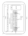
- FIG. 3 is a general diagram of a GUI 70 to the NAS device 22 which is viewable from a display 72 of a user workstation 24 ( FIG. 1 ).
- the GUI 70 takes the form of a web page which is provided by the web server 66 running on the NAS device 22 ; such an arrangement is well suited for a general purpose computer running a web browser.
- the GUI 70 takes the form of an independent window which is rendered on the display 72 of the user workstation 24 by specialized client software (e.g., an installed computer program product) running on the user workstation 24 .
- the GUI 70 includes, among other things (e.g., a title bar, a help pane, etc.), a tabs area 74 which allows a user to select one of multiple tabs, and a main viewing area 76 which operates as a dialog box based on the particular selected tab in the tabs area 74 .
- FIG. 3 shows the “camera settings” tab as being selected in the tabs area 74 . Accordingly, information regarding the video cameras 26 ( FIG. 1 ) is presented in the main viewing area 76 of the GUI 70 .
- the main viewing area 76 includes rows 78 associated with each video camera 26 detected by the NAS device 22 .
- the NAS device 22 has detected a front door camera and a rear door camera.
- action icons 80 associated with features each detected camera 26 which, if selected by the user, give the user various types of control over that camera 26 . Examples of such control features include displaying camera status, changing camera operating parameters, and rendering live video from the camera 26 .
- Such information and status 82 includes camera names, amounts of storage space consumed by video data recorded from the video cameras 26 (e.g., the size of MPEG files), and the model/types of cameras 26 (hi-res, zoom, etc.).
- a recording control area 84 e.g., radio buttons for each camera 26 .
- a recording control area 84 e.g., radio buttons for each camera 26
- Any changes are preferably committed when the user clicks on an “OK” button 86 .
- the user to direct the NAS device 22 to store video data from a particular video camera 26 .
- the user clicks on a particular graphic (e.g., a radio button) in the recording control area 84 for that camera 26 , and then clicks on the “OK” button 86 .
- the user workstation 26 sends a video store command to the NAS device 22 through the network 22 (e.g., see the video command 36 in FIG. 1 ).
- the NAS device 22 Upon receipt of the video store command, the NAS device 22 records video data from that video camera 26 (e.g., see the camera output signals 40 and the camera control signals 42 in FIG. 1 ). Since the NAS device 22 obtains the video data directly from the video camera 26 , the user workstation 26 does not need to process any video data from the video camera 26 . Moreover, the recorded video data is robustly and reliably stored on the NAS device 22 , e.g., the video data enjoys the file sharing, backup and restoration advantages provided by the NAS device 22 .
- the user can view live video by operating the GUI 70 .
- a particular video camera 26 e.g., the Front Door Camera
- the user clicks on a particular icon e.g., a display icon
- the user workstation 26 sends a video view command to the NAS device 22 through the network 22 (e.g., see the video command 36 in FIG. 1 ).
- the NAS device 22 Upon receipt of the video view command, the NAS device 22 provide the user workstation 26 with particular configuration details to enable the user workstation 26 to receive live video data directly from the video camera 26 (e.g., see the user workstation reply messages 38 , camera output signals 40 and the camera control signals 42 in FIG. 1 ). Since the user workstation 26 obtains the live video data directly from the video camera 26 , the NAS device 22 is not burdened with additional overhead in relaying live video data from the video camera 26 to the user workstation 24 . Further details will now be provided with reference to FIG. 4 .
- FIG. 4 is a block diagram which illustrates interaction of particular components of the system 20 which are involved in accessing video data in accordance with a web-based implementation.
- the NAS device 22 includes a web server 102 for the GUI 70 ( FIG. 3 ) and dedicated storage services 104 for handling the video data (e.g., MPEG-4 format) and other files).
- the user workstation 24 includes user I/O 106 (e.g., a keyboard, mouse and display), a web browser 108 , and a media player 110 .
- the NAS device 22 receives control from the user workstation 24 , and provides both the GUI 70 (using HTTP) and access to recorded video data to the user workstation (e.g., using RTP) among other data storage services.
- the NAS device 22 then directly records video data from the video camera 26 and imposes control over the video camera 26 .
- the web browser 108 For access to live video from the video camera 26 , the web browser 108 receives a metafile 112 from the web server 102 of the NAS device 22 in response to a video view command entered into the GUI 70 , and passes the metafile 112 to the media player 110 . The media player 110 is then able to obtain and render live video directly from the video camera 26 (e.g., using RTSP).
- the system 20 includes sensing capabilities, e.g., detection of activity or motion within a field of view. Such sensing may involve activation of a sensor at the video camera 26 , or alternatively processing video data within the NAS device 22 to detect the activity. Upon such detection, the NAS device 22 is able to send a notification signal (e.g., event notification) to the user workstation 24 or similar external device (e.g., an alarm, a telephone, etc.).
- a notification signal e.g., event notification
- the video camera 26 includes encryption capabilities to encryption the video data
- the NAS device 22 and the user workstation 24 include decryption capabilities to decrypt the video data.
- FIG. 5 is a flowchart of a procedure 200 which is performed by the NAS device 22 .
- the procedure 200 is performed for each video camera 26 of the system 20 .
- the procedure 200 is reliably performed by the NAS device 22 while the NAS device 22 concurrently carries out dedicated data storage server operations on behalf of the user workstations 24 , i.e., I/O operations, backup tasks and file restorations which are traditional to a dedicated self-contained data storage server rather than a conventional general purpose computer.
- dedicated data storage server operations i.e., I/O operations, backup tasks and file restorations which are traditional to a dedicated self-contained data storage server rather than a conventional general purpose computer.
- the NAS device 22 detects access to a video camera 26 through the network 26 .
- detection involves discovery, as well as additional configuration, occur via UPnP.
- the NAS device 22 receives a video store command from a user workstation 24 through the network 26 .
- the video store command directs the NAS device 22 to store video data provided by the video camera 22 to the NAS device through the network 26 .
- the NAS device 22 stores the video data provided by the video camera 26 in response to the video store command.
- the NAS device 22 obtains such video data directly from the video camera 26 rather than through another device.
- the stored video data e.g., a file in MPEG-4 format
- an improved NAS device 22 is well-suited for providing access to video data.
- a NAS device 22 is capable of detecting access to a video camera 26 from the NAS device 22 through a network 28 , e.g., using UPnP auto discovery.
- Such a NAS device 22 is further capable of robustly and reliably receiving and storing video data directly from the video camera 26 through the network 28 . Since the NAS device 22 obtains the video data directly from the video camera 26 , external video processing equipment (e.g., a DVR or general purpose computer) does not need to process any video data from the video camera 26 .
- external video processing equipment e.g., a DVR or general purpose computer
Abstract
Description
Claims (16)
Priority Applications (1)
| Application Number | Priority Date | Filing Date | Title |
|---|---|---|---|
| US12/211,235 US8300098B1 (en) | 2008-09-16 | 2008-09-16 | Techniques for providing access to video data using a network attached storage device |
Applications Claiming Priority (1)
| Application Number | Priority Date | Filing Date | Title |
|---|---|---|---|
| US12/211,235 US8300098B1 (en) | 2008-09-16 | 2008-09-16 | Techniques for providing access to video data using a network attached storage device |
Publications (1)
| Publication Number | Publication Date |
|---|---|
| US8300098B1 true US8300098B1 (en) | 2012-10-30 |
Family
ID=47045780
Family Applications (1)
| Application Number | Title | Priority Date | Filing Date |
|---|---|---|---|
| US12/211,235 Active 2031-08-31 US8300098B1 (en) | 2008-09-16 | 2008-09-16 | Techniques for providing access to video data using a network attached storage device |
Country Status (1)
| Country | Link |
|---|---|
| US (1) | US8300098B1 (en) |
Cited By (11)
| Publication number | Priority date | Publication date | Assignee | Title |
|---|---|---|---|---|
| US20090007016A1 (en) * | 2007-06-29 | 2009-01-01 | Nokia Corporation | Communication channel indicators |
| US20130007540A1 (en) * | 2011-06-30 | 2013-01-03 | Axis Ab | Method for increasing reliability in monitoring systems |
| US20150095776A1 (en) * | 2013-10-01 | 2015-04-02 | Western Digital Technologies, Inc. | Virtual manifestation of a nas or other devices and user interaction therewith |
| US20170264604A1 (en) * | 2016-03-08 | 2017-09-14 | Dean Drako | Apparatus for sharing private video streams with first responders and method of operation |
| US20190268626A1 (en) * | 2016-03-08 | 2019-08-29 | Dean Drako | Apparatus for sharing private video streams with first responders and mobile method of operation |
| US20190342526A1 (en) * | 2016-03-08 | 2019-11-07 | Dean Drako | System and apparatus for sharing private video streams with first responders |
| US20200014964A1 (en) * | 2016-03-08 | 2020-01-09 | Dean Drako | Apparatus for sharing private video streams with public service agencies |
| US11343544B2 (en) | 2020-06-29 | 2022-05-24 | Seagate Technology Llc | Selective use of cameras in a distributed surveillance system |
| US11381605B2 (en) * | 2016-03-08 | 2022-07-05 | Eagle Eye Networks, Inc. | System, methods, and apparatus for sharing private video stream assets with first responders |
| US11463739B2 (en) | 2020-06-29 | 2022-10-04 | Seagate Technology Llc | Parameter based load balancing in a distributed surveillance system |
| US11503381B2 (en) | 2020-06-29 | 2022-11-15 | Seagate Technology Llc | Distributed surveillance system with abstracted functional layers |
Citations (34)
| Publication number | Priority date | Publication date | Assignee | Title |
|---|---|---|---|---|
| US6525761B2 (en) * | 1996-07-23 | 2003-02-25 | Canon Kabushiki Kaisha | Apparatus and method for controlling a camera connected to a network |
| US20030067387A1 (en) * | 2001-10-05 | 2003-04-10 | Kwon Sung Bok | Remote control and management system |
| US20030079016A1 (en) * | 2001-10-23 | 2003-04-24 | Sheng (Ted) Tai Tsao | Using NAS appliance to build a non-conventional distributed video server |
| US20030117500A1 (en) * | 2001-12-24 | 2003-06-26 | Icp Electronics Inc. | Network video recording system |
| US20040049797A1 (en) | 2002-02-25 | 2004-03-11 | Oak Technology, Inc. | Network interface to a video device |
| US20040080615A1 (en) * | 2002-08-21 | 2004-04-29 | Strategic Vista Intenational Inc. | Digital video security system |
| US20040117836A1 (en) * | 2002-12-11 | 2004-06-17 | Jeyhan Karaoguz | Method and system for network storage in a media exchange network |
| US20050078180A1 (en) * | 2002-12-13 | 2005-04-14 | Minoru Nakamura | Camera control system, camera server, client, control method, and recording medium |
| US20050235336A1 (en) | 2004-04-15 | 2005-10-20 | Kenneth Ma | Data storage system and method that supports personal video recorder functionality |
| US20060020960A1 (en) * | 2004-03-24 | 2006-01-26 | Sandeep Relan | System, method, and apparatus for secure sharing of multimedia content across several electronic devices |
| US20060248038A1 (en) * | 2005-04-29 | 2006-11-02 | Marc Kaplan | System and method of handling file metadata |
| US20060271695A1 (en) * | 2005-05-16 | 2006-11-30 | Electronics Line 3000 Ltd. | System for remote secured operation, monitoring and control of security and other types of events |
| US20060279628A1 (en) * | 2003-09-12 | 2006-12-14 | Fleming Hayden G | Streaming non-continuous video data |
| US20060284981A1 (en) * | 2005-06-20 | 2006-12-21 | Ricoh Company, Ltd. | Information capture and recording system |
| US20070022185A1 (en) * | 2005-07-25 | 2007-01-25 | Stuart Hamilton | Simple home networking |
| US20070098397A1 (en) * | 2005-11-01 | 2007-05-03 | D-Link Systems, Inc. | Network camera |
| US20070183768A1 (en) * | 2000-07-26 | 2007-08-09 | Livewave, Inc. | Methods and systems for networked camera control |
| US20070199032A1 (en) * | 2004-09-23 | 2007-08-23 | Renkis Martin A | Wireless surveillance system releasably mountable to track lighting |
| US7382244B1 (en) | 2007-10-04 | 2008-06-03 | Kd Secure | Video surveillance, storage, and alerting system having network management, hierarchical data storage, video tip processing, and vehicle plate analysis |
| US7386872B2 (en) * | 2001-07-04 | 2008-06-10 | Fujitsu Limited | Network storage type video camera system |
| US7460149B1 (en) | 2007-05-28 | 2008-12-02 | Kd Secure, Llc | Video data storage, search, and retrieval using meta-data and attribute data in a video surveillance system |
| US20080303903A1 (en) * | 2003-12-02 | 2008-12-11 | Connexed Technologies Inc. | Networked video surveillance system |
| US20090015672A1 (en) * | 2007-07-13 | 2009-01-15 | Glenn Daniel Clapp | Systems and methods for geographic video interface and collaboration |
| US20090027495A1 (en) * | 2007-07-25 | 2009-01-29 | Stas Oskin | Internet visual surveillance and management technology for telecommunications, Internet, cellular and other communications companies |
| US20090031381A1 (en) * | 2007-07-24 | 2009-01-29 | Honeywell International, Inc. | Proxy video server for video surveillance |
| US7496647B2 (en) | 2002-12-11 | 2009-02-24 | Broadcom Corporation | Personal inter-home media exchange network |
| US7500246B2 (en) | 2001-09-26 | 2009-03-03 | Emc Corporation | Sharing objects between computer systems |
| US20090085740A1 (en) * | 2007-09-27 | 2009-04-02 | Thierry Etienne Klein | Method and apparatus for controlling video streams |
| US20090136030A1 (en) * | 2006-11-21 | 2009-05-28 | Vimicro Corporation | Video monitoring system with video signal encrypted and the and method for the same |
| US7543327B1 (en) * | 2003-11-21 | 2009-06-02 | Arecont Vision Llc | Video surveillance system based on high resolution network cameras capable of concurrent transmission of multiple image formats at video rates |
| US7555613B2 (en) | 2004-05-11 | 2009-06-30 | Broadcom Corporation | Storage access prioritization using a data storage device |
| US20100007731A1 (en) * | 2008-07-14 | 2010-01-14 | Honeywell International Inc. | Managing memory in a surveillance system |
| US20100217837A1 (en) * | 2006-12-29 | 2010-08-26 | Prodea Systems , Inc. | Multi-services application gateway and system employing the same |
| US7859571B1 (en) * | 1999-08-12 | 2010-12-28 | Honeywell Limited | System and method for digital video management |
-
2008
- 2008-09-16 US US12/211,235 patent/US8300098B1/en active Active
Patent Citations (34)
| Publication number | Priority date | Publication date | Assignee | Title |
|---|---|---|---|---|
| US6525761B2 (en) * | 1996-07-23 | 2003-02-25 | Canon Kabushiki Kaisha | Apparatus and method for controlling a camera connected to a network |
| US7859571B1 (en) * | 1999-08-12 | 2010-12-28 | Honeywell Limited | System and method for digital video management |
| US20070183768A1 (en) * | 2000-07-26 | 2007-08-09 | Livewave, Inc. | Methods and systems for networked camera control |
| US7386872B2 (en) * | 2001-07-04 | 2008-06-10 | Fujitsu Limited | Network storage type video camera system |
| US7500246B2 (en) | 2001-09-26 | 2009-03-03 | Emc Corporation | Sharing objects between computer systems |
| US20030067387A1 (en) * | 2001-10-05 | 2003-04-10 | Kwon Sung Bok | Remote control and management system |
| US20030079016A1 (en) * | 2001-10-23 | 2003-04-24 | Sheng (Ted) Tai Tsao | Using NAS appliance to build a non-conventional distributed video server |
| US20030117500A1 (en) * | 2001-12-24 | 2003-06-26 | Icp Electronics Inc. | Network video recording system |
| US20040049797A1 (en) | 2002-02-25 | 2004-03-11 | Oak Technology, Inc. | Network interface to a video device |
| US20040080615A1 (en) * | 2002-08-21 | 2004-04-29 | Strategic Vista Intenational Inc. | Digital video security system |
| US20040117836A1 (en) * | 2002-12-11 | 2004-06-17 | Jeyhan Karaoguz | Method and system for network storage in a media exchange network |
| US7496647B2 (en) | 2002-12-11 | 2009-02-24 | Broadcom Corporation | Personal inter-home media exchange network |
| US20050078180A1 (en) * | 2002-12-13 | 2005-04-14 | Minoru Nakamura | Camera control system, camera server, client, control method, and recording medium |
| US20060279628A1 (en) * | 2003-09-12 | 2006-12-14 | Fleming Hayden G | Streaming non-continuous video data |
| US7543327B1 (en) * | 2003-11-21 | 2009-06-02 | Arecont Vision Llc | Video surveillance system based on high resolution network cameras capable of concurrent transmission of multiple image formats at video rates |
| US20080303903A1 (en) * | 2003-12-02 | 2008-12-11 | Connexed Technologies Inc. | Networked video surveillance system |
| US20060020960A1 (en) * | 2004-03-24 | 2006-01-26 | Sandeep Relan | System, method, and apparatus for secure sharing of multimedia content across several electronic devices |
| US20050235336A1 (en) | 2004-04-15 | 2005-10-20 | Kenneth Ma | Data storage system and method that supports personal video recorder functionality |
| US7555613B2 (en) | 2004-05-11 | 2009-06-30 | Broadcom Corporation | Storage access prioritization using a data storage device |
| US20070199032A1 (en) * | 2004-09-23 | 2007-08-23 | Renkis Martin A | Wireless surveillance system releasably mountable to track lighting |
| US20060248038A1 (en) * | 2005-04-29 | 2006-11-02 | Marc Kaplan | System and method of handling file metadata |
| US20060271695A1 (en) * | 2005-05-16 | 2006-11-30 | Electronics Line 3000 Ltd. | System for remote secured operation, monitoring and control of security and other types of events |
| US20060284981A1 (en) * | 2005-06-20 | 2006-12-21 | Ricoh Company, Ltd. | Information capture and recording system |
| US20070022185A1 (en) * | 2005-07-25 | 2007-01-25 | Stuart Hamilton | Simple home networking |
| US20070098397A1 (en) * | 2005-11-01 | 2007-05-03 | D-Link Systems, Inc. | Network camera |
| US20090136030A1 (en) * | 2006-11-21 | 2009-05-28 | Vimicro Corporation | Video monitoring system with video signal encrypted and the and method for the same |
| US20100217837A1 (en) * | 2006-12-29 | 2010-08-26 | Prodea Systems , Inc. | Multi-services application gateway and system employing the same |
| US7460149B1 (en) | 2007-05-28 | 2008-12-02 | Kd Secure, Llc | Video data storage, search, and retrieval using meta-data and attribute data in a video surveillance system |
| US20090015672A1 (en) * | 2007-07-13 | 2009-01-15 | Glenn Daniel Clapp | Systems and methods for geographic video interface and collaboration |
| US20090031381A1 (en) * | 2007-07-24 | 2009-01-29 | Honeywell International, Inc. | Proxy video server for video surveillance |
| US20090027495A1 (en) * | 2007-07-25 | 2009-01-29 | Stas Oskin | Internet visual surveillance and management technology for telecommunications, Internet, cellular and other communications companies |
| US20090085740A1 (en) * | 2007-09-27 | 2009-04-02 | Thierry Etienne Klein | Method and apparatus for controlling video streams |
| US7382244B1 (en) | 2007-10-04 | 2008-06-03 | Kd Secure | Video surveillance, storage, and alerting system having network management, hierarchical data storage, video tip processing, and vehicle plate analysis |
| US20100007731A1 (en) * | 2008-07-14 | 2010-01-14 | Honeywell International Inc. | Managing memory in a surveillance system |
Cited By (18)
| Publication number | Priority date | Publication date | Assignee | Title |
|---|---|---|---|---|
| US10225389B2 (en) * | 2007-06-29 | 2019-03-05 | Nokia Technologies Oy | Communication channel indicators |
| US20090007016A1 (en) * | 2007-06-29 | 2009-01-01 | Nokia Corporation | Communication channel indicators |
| US20130007540A1 (en) * | 2011-06-30 | 2013-01-03 | Axis Ab | Method for increasing reliability in monitoring systems |
| US8977889B2 (en) * | 2011-06-30 | 2015-03-10 | Axis Ab | Method for increasing reliability in monitoring systems |
| US20150095776A1 (en) * | 2013-10-01 | 2015-04-02 | Western Digital Technologies, Inc. | Virtual manifestation of a nas or other devices and user interaction therewith |
| US10505923B2 (en) * | 2016-03-08 | 2019-12-10 | Dean Drako | Apparatus for sharing private video streams with first responders and method of operation |
| US20190268626A1 (en) * | 2016-03-08 | 2019-08-29 | Dean Drako | Apparatus for sharing private video streams with first responders and mobile method of operation |
| US20190342526A1 (en) * | 2016-03-08 | 2019-11-07 | Dean Drako | System and apparatus for sharing private video streams with first responders |
| US20170264604A1 (en) * | 2016-03-08 | 2017-09-14 | Dean Drako | Apparatus for sharing private video streams with first responders and method of operation |
| US20200014964A1 (en) * | 2016-03-08 | 2020-01-09 | Dean Drako | Apparatus for sharing private video streams with public service agencies |
| US10674116B2 (en) * | 2016-03-08 | 2020-06-02 | Eagle Eye Networks, Inc | System and apparatus for sharing private video streams with first responders |
| US10848808B2 (en) * | 2016-03-08 | 2020-11-24 | Eagle Eye Networks, Inc. | Apparatus for sharing private video streams with public service agencies |
| US10939141B2 (en) * | 2016-03-08 | 2021-03-02 | Eagle Eye Networks, Inc. | Apparatus for sharing private video streams with first responders and mobile method of operation |
| US11381605B2 (en) * | 2016-03-08 | 2022-07-05 | Eagle Eye Networks, Inc. | System, methods, and apparatus for sharing private video stream assets with first responders |
| US11909774B1 (en) * | 2016-03-08 | 2024-02-20 | Eagle Eye Networks, Inc | Method and system for sharing private video stream assets with first responders |
| US11343544B2 (en) | 2020-06-29 | 2022-05-24 | Seagate Technology Llc | Selective use of cameras in a distributed surveillance system |
| US11463739B2 (en) | 2020-06-29 | 2022-10-04 | Seagate Technology Llc | Parameter based load balancing in a distributed surveillance system |
| US11503381B2 (en) | 2020-06-29 | 2022-11-15 | Seagate Technology Llc | Distributed surveillance system with abstracted functional layers |
Similar Documents
| Publication | Publication Date | Title |
|---|---|---|
| US8300098B1 (en) | Techniques for providing access to video data using a network attached storage device | |
| TWI452482B (en) | Methods, computer-readable mediums, and computer systems for selectively restricting the placeshifting of copy protected digital media content | |
| US8601087B2 (en) | Configuring channels for sharing media | |
| US20210373720A1 (en) | Technologies for computing context replay with visual searching | |
| WO2019206243A1 (en) | Material display method, terminal, and computer storage medium | |
| CN102843496A (en) | Video collecting processing method and portable electronic device | |
| US20120210215A1 (en) | Method and apparatus for providing networked assistance and feedback control for consumer electronic devices | |
| US20150007070A1 (en) | Image-based application automation | |
| US10178170B2 (en) | Browser-based virtual media administration | |
| US11843815B2 (en) | Interfacing a television with a second device | |
| JP5819488B2 (en) | Adjusting a transmissive display with an image capture device | |
| US20080143831A1 (en) | Systems and methods for user notification in a multi-use environment | |
| US10311160B2 (en) | Cloud search analytics | |
| Salem et al. | Digital video recorder for Raspberry PI cameras with multi-camera synchronous acquisition | |
| CN109660581B (en) | Physical machine management method, device and system | |
| CN113938642A (en) | Distributed monitoring system with abstraction function layer | |
| US8824872B2 (en) | Display control apparatus, reproduction system, and recording medium in which display control is performed based on a detected event | |
| US20070220364A1 (en) | Method for capturing a display frame of a computer crashing | |
| US7356683B2 (en) | System and method for monitoring BIOS messages of remote computers by a local server | |
| US20140143309A1 (en) | Network interface card and method for displaying information of network interface card | |
| EP2879346A1 (en) | Processing method for securing electronic documents | |
| US11075996B2 (en) | Remote dashboard console | |
| CN107749892B (en) | Network reading method and device for conference record, intelligent tablet and storage medium | |
| US20140358992A1 (en) | Images monitoring and broadcasting system and method | |
| MXPA04010508A (en) | Remote key manager. |
Legal Events
| Date | Code | Title | Description |
|---|---|---|---|
| AS | Assignment |
Owner name: EMC CORPORATION, MASSACHUSETTS Free format text: ASSIGNMENT OF ASSIGNORS INTEREST;ASSIGNORS:GRUTTADAURIA, BRIAN;SAREEN, SHYAM;FRANK, JOSEPH;AND OTHERS;REEL/FRAME:021636/0212 Effective date: 20080908 |
|
| STCF | Information on status: patent grant |
Free format text: PATENTED CASE |
|
| AS | Assignment |
Owner name: LENOVOEMC LIMITED, HONG KONG Free format text: ASSIGNMENT OF ASSIGNORS INTEREST;ASSIGNOR:EMC CORPORATION;REEL/FRAME:030868/0948 Effective date: 20121217 |
|
| FPAY | Fee payment |
Year of fee payment: 4 |
|
| MAFP | Maintenance fee payment |
Free format text: PAYMENT OF MAINTENANCE FEE, 8TH YEAR, LARGE ENTITY (ORIGINAL EVENT CODE: M1552); ENTITY STATUS OF PATENT OWNER: LARGE ENTITY Year of fee payment: 8 |
|
| MAFP | Maintenance fee payment |
Free format text: PAYMENT OF MAINTENANCE FEE, 12TH YEAR, LARGE ENTITY (ORIGINAL EVENT CODE: M1553); ENTITY STATUS OF PATENT OWNER: LARGE ENTITY Year of fee payment: 12 |