US8301593B2 - Mixed mode synchronous and asynchronous replication system - Google Patents
Mixed mode synchronous and asynchronous replication system Download PDFInfo
- Publication number
- US8301593B2 US8301593B2 US12/483,849 US48384909A US8301593B2 US 8301593 B2 US8301593 B2 US 8301593B2 US 48384909 A US48384909 A US 48384909A US 8301593 B2 US8301593 B2 US 8301593B2
- Authority
- US
- United States
- Prior art keywords
- transaction
- replication
- application
- node
- synchronous
- Prior art date
- Legal status (The legal status is an assumption and is not a legal conclusion. Google has not performed a legal analysis and makes no representation as to the accuracy of the status listed.)
- Active, expires
Links
Images


Classifications
-
- G—PHYSICS
- G06—COMPUTING; CALCULATING OR COUNTING
- G06F—ELECTRIC DIGITAL DATA PROCESSING
- G06F11/00—Error detection; Error correction; Monitoring
- G06F11/07—Responding to the occurrence of a fault, e.g. fault tolerance
- G06F11/16—Error detection or correction of the data by redundancy in hardware
- G06F11/20—Error detection or correction of the data by redundancy in hardware using active fault-masking, e.g. by switching out faulty elements or by switching in spare elements
- G06F11/2053—Error detection or correction of the data by redundancy in hardware using active fault-masking, e.g. by switching out faulty elements or by switching in spare elements where persistent mass storage functionality or persistent mass storage control functionality is redundant
- G06F11/2094—Redundant storage or storage space
-
- G—PHYSICS
- G06—COMPUTING; CALCULATING OR COUNTING
- G06F—ELECTRIC DIGITAL DATA PROCESSING
- G06F11/00—Error detection; Error correction; Monitoring
- G06F11/07—Responding to the occurrence of a fault, e.g. fault tolerance
- G06F11/16—Error detection or correction of the data by redundancy in hardware
- G06F11/20—Error detection or correction of the data by redundancy in hardware using active fault-masking, e.g. by switching out faulty elements or by switching in spare elements
- G06F11/2097—Error detection or correction of the data by redundancy in hardware using active fault-masking, e.g. by switching out faulty elements or by switching in spare elements maintaining the standby controller/processing unit updated
Definitions
- An enterprise's data is its lifeblood. Lose its data, and the enterprise is likely to fail. Therefore, it is imperative for a company to maintain a copy of its data at some remote site that is impervious to a catastrophe that might cause the primary copy of the data to be lost.
- a major decision that a company must make is how much data loss it can tolerate following not only a catastrophe, but also following an ordinary failure of its primary processing facility. This is known as the company's Recovery Point Objective, or RPO.
- RPO Recovery Point Objective
- Classic backup techniques support RPOs measured in hours or days—this is the amount of data that might be lost following the failure of the processing system. Data replication technology can reduce this to seconds (asynchronous replication) or even to zero (synchronous replication).
- active/active systems can provide recovery times measured in seconds or subseconds.
- multiple geographically-distributed nodes cooperate in a common application, executing transactions against local copies of the application database. Should a node fail, it is only necessary to reroute users or transactions to one or more surviving nodes. This can be accomplished in seconds or subseconds. It is important that the database copies be kept in close or exact synchronism. This can only be done by replicating in real time changes made to one database copy to the other database copies in the application network.
- a method for operating a replication system that includes an asynchronous replication mode and a synchronous replication mode.
- the replication system replicates data associated with a plurality of transactions from an originating node to one or more target nodes, the target nodes connected via communication media in a topology, each target node including a database and a plurality of appliers allocated thereto.
- Each transaction being replicated may encompass one or more transaction steps or operations.
- the replication system allocates a first set of transaction steps or operations to the plurality of appliers on an object-by-object basis when the replication system operates in asynchronous replication mode. It also allocates a second set of transaction steps or operations to the plurality of appliers on a transaction-by-transaction basis when the replication system operates in synchronous replication mode.
- the replication system is configured for bidirectional replication where a target node can also be an originating node and vice versa.
- the first set of transactions steps or operations and the second set of transaction steps or operations may overlap and include some or all of the same transaction steps or operations. In other embodiments, the first and second sets of transaction steps or operations do not overlap.
- the objects to be replicated are a range of rows of a database table.
- the range of rows is contained in a database or table partition.
- the plurality of appliers are located at the target node and may be separate processes.
- the separate processes may be a single-multithreaded process or multiple threads in multiple processes.
- the replication system allocates all transaction steps or operations to the plurality of appliers on an object-by-object basis when the replication system operates in a asynchronous replication mode.
- the replication system allocates all transaction steps or operations to the plurality of appliers on a transaction-by-transaction basis when the replication system operates in a synchronous replication mode.
- the replication system allocates a third set of transaction steps or operations to the plurality of appliers on a transaction-by-transaction basis when the replication system operates in an asynchronous replication mode. Yet another embodiment allocates a fourth set of transaction steps or operations to the plurality of appliers on an object-by-object basis when the replication system operates in synchronous replication mode.
- the replication system switches from the synchronous replication mode to the asynchronous mode when synchronous replication cannot be ensured.
- Synchronous replication may not be ensured when, for example, the communication network is not operational.
- the replication system operates in the mode where it is allocating a first set of transaction steps or operations to the plurality of appliers on an object-by-object basis when the replication system is operating in asynchronous replication mode, switches from the asynchronous replication mode to the synchronous mode by: (i) allocating selective transaction steps or operations to the plurality of appliers on an object-by-object basis in a synchronous replication mode, and (ii) allocating selective transaction steps or operations according to the embodiment where the transaction steps or operations are allocated on a transaction-by-transaction basis when the replication system operates in synchronous replication mode.
- the replication system includes an originating node and the method further comprises preventing selective transaction steps or operations that are requested to execute on the originating node from being initiated when replication cannot be ensured. This may prevent, for example, the originating node database from diverging from the target node database in times of network outage.
- the replication system includes an originating node, but the target node is remote from the originating node. However, in other embodiments the target node is co-located with the originating node. Additionally, the plurality of appliers in the replication system may be at the same target node, other target nodes, or the originating node.
- the replication system further includes one or more originating nodes, the method further comprises initiating requests for the first and second sets of transaction steps or operations to execute on an originating node during the same time period, wherein the allocation steps occur after the requests are initiated and during the same time period.
- the allocation of the first and/or second set of transaction steps or operations are performed by an application.
- the application might, for example, have built into it logic which identifies important transactions which must be replicated synchronously.
- the application uses an intercept library to do the allocation process.
- the replication system includes an asynchronous replication mode and a synchronous replication mode that can both operate during the same time period (that is, both modes can replicate transaction steps or operations without taking turns and while the other replication mode is in operation) to replicate data associated with a plurality of transactions from the one or more originating nodes to the same target node.
- a first set of transaction steps or operations is identified that are requested to execute on the originating node to the replication system for replication to one of the target nodes in an asynchronous replication mode.
- a second set of transaction steps or operations is identified that are requested to execute on the originating node to the replication system for replication to the same target node in a synchronous replication mode.
- a plurality of appliers is used to replicate the first and second set of transaction steps or operations in their respective asynchronous and synchronous replication modes.
- the transaction steps or operations that are requested to execute on the originating node occur during the same time period, thereby allowing different sets of transaction steps or operations to be replicated to the same node asynchronously and synchronously during the same time period.
- the synchronous replication uses coordinated commits and in others, it uses dual writes or another other synchronous replication technique.
- An actual embodiment of the present invention is the Shadowbase e® Plus SRTM product from Gravic, Inc., Malvern, Pa. (WorldwideWeb.gravic.com).
- This embodiment of the present invention is a computer software application which precludes data loss, has a rapid response time (i.e., low latency) with full disaster tolerance, operates with bidirectional active/active capabilities, reduces data loss following a node failure to zero, and recovers services fast enough so that the application users may not even realize the occurrence of system failures. True disaster tolerance is thereby achieved since users experience no interruption in their data processing services.
- the scope of the present invention is not limited to the Shadowbase embodiment and includes other embodiments that provide similar functionality.
- FIG. 1 Data Replication, shows a prior art replication system.
- FIG. 2 Data Replication Engine, shows a prior art replication engine.
- FIG. 3 Asynchronous Data Replication, shows a prior art asynchronous replication system.
- FIG. 4 Asynchronous Data Loss Following Source Node Failure, depicts the classic prior art data loss problem for an asynchronous data replication system when the source node fails.
- FIG. 5 Transactions, shows the prior art sequencing and flow of transaction steps or operations in a data replication system.
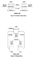
- FIG. 6 Coordinated Commits, shows the prior art architecture of the coordinated commits approach to synchronous replication.
- FIG. 7 Coordinated Commit Sequence Diagram, shows the prior art sequence diagram of the coordinated commits approach to synchronous replication.
- FIG. 8 Distributed Lock Management, shows the prior art architecture for the distributed lock management form of synchronous replication.
- FIG. 9 Application Latency, depicts the application latency imposed by the prior art network transactions and coordinated commits approaches to synchronous replication.
- FIG. 10 Bidirectional Replication, depicts the classic prior art architecture for bidirectional replication.
- FIG. 11 Ping-Ponging, depicts the classic prior art problem inherent with classic bidirectional replication that must be overcome by a replication engine to work successfully in a bidirectional mode.
- FIG. 12 Data Collisions, depicts the classic prior art problem that can occur in bidirectional replication when the application on two or more nodes updates the same data item at the same time, causing a data collision.
- FIG. 13 Partitioning, depicts the prior art approach to avoid data collisions in a bidirectional replication system by dividing the work load or transaction load into discreet sets that do not overlap, and assigning the workload to specific nodes for processing, to avoid data collisions.
- FIG. 14 depicts the prior art approach for performing relative replication (i.e., a method to resolve data collisions when numerical fields or values are updated on more than one node at the same time).
- FIG. 15 Master/Slave, depicts the prior art architecture and approach of a master/slave replication system for resolving data collisions.
- FIG. 16 Distributed Deadlocks, depicts the prior art problem that can occur in a bidirectional synchronous replication system whereby the same data item is locked on more than one database at a time, with each side being granted its local lock but then deadlocking on the request to be granted the lock on the remote copy of that data item.
- FIG. 17 Split-Brain Mode, depicts the prior art problem that can occur in a synchronous bidirectional replication system that is running an active/active architecture when the interconnecting network fails or is otherwise unavailable.
- neither side can complete its synchronous replication work, and if allowed to run in the asynchronous mode, with an update anywhere (non-partitioned) algorithm, data collisions can occur (i.e., neither side knows what the other side is doing).
- FIG. 18 The RPO/RTO Relationship, depicts the prior art relationship between the business continuity recovery point objective, which is a measure of data loss at a failure, with the recovery time objective, which is a measure of the speed of recovery of the replication system (and/or application services) to users when a failure occurs.
- FIG. 19 Magnetic Tape, depicts the classic prior art architecture for recovering from a failure using magnetic tape as the recovery media, and shows that the recovery time is generally many hours to days.
- FIG. 20 Virtual Tape, depicts the classic prior art architecture for recovering from a failure using virtual tape (i.e., tape drive media emulated in a disk environment) as the recovery media, and shows that recovery time is generally hours.
- virtual tape i.e., tape drive media emulated in a disk environment
- FIG. 21 Cluster, depicts the classic prior art architecture used in a high availability cluster failover approach, and shows that the recovery time is generally minutes.
- FIG. 22 Unidirectional Replication, depicts the prior art active/passive architecture of a unidirectional replication system, and shows that the recovery time is generally minutes or less.
- FIG. 23 Shows the prior art active/“almost active” architecture of a bidirectional replication system configured in the sizzling hot standby (or takeover) mode, and shows that the recovery time is generally seconds or less.
- FIG. 24 depicts the prior art architecture of a bidirectional active/active replication system and shows that the recovery time is generally seconds or less.
- FIG. 25 Business Continuity Continuum, is a prior art depiction of where the various prior art technologies fall in the RPO vs RTO continuum.
- FIG. 26 Typical RTOs, RPOs, Configurations, and Applications, depicts the prior art matrix of how asynchronous and synchronous replication impacts RTO and RPO, typical architectures and configurations, and typical applications.
- FIG. 27 Shows the prior art Shadowbase asynchronous replication engine when configured in a unidirectional mode.
- FIG. 28 Shows the prior art Shadowbase asynchronous replication engine when configured in a bidirectional mode.
- FIG. 29 The X/Open Distributed Transaction Processing Model, depicts the prior art X/Open transaction processing architecture.
- FIG. 30 depicts the prior art transaction monitoring facility and gateway communications, available from HP.
- FIG. 31 Transaction State Transitions for Volatile Resource Manager, depicts the prior art state transition table for a volatile resource manager in a TMF environment.
- FIG. 32 Coordinated Commit Replication, depicts a preferred embodiment architecture (detailed) of the coordinated commit synchronous replication approach implemented via a volatile resource manager in the TMF environment.
- FIG. 33 Coordinated Commit Replication Sequence Diagram, depicts a preferred embodiment sequence diagram of the coordinated commit synchronous replication sequence implemented via a volatile resource manager in the TMF environment.
- FIG. 34 Shows the process architecture of a preferred embodiment of the invention.
- FIG. 35 Beginning a Transaction, depicts a process architecture of how to being and register a transaction in a preferred embodiment of the present invention.
- FIG. 36 Beginning a Transaction, depicts a sequence diagram of how to register a transaction in a preferred embodiment of the present invention.
- FIG. 37 Replicate Changes, depicts a process architecture of how to replicate database transactions and changes in a preferred embodiment of the present invention.
- FIG. 38 Replicate Changes, depicts a sequence diagram of how to replicate database transactions and changes in a preferred embodiment of the present invention.
- FIG. 39 Communication a Transaction—Phase 1, depicts a process architecture of how the Phase 1 sequence of the 2-phase commit protocol occurs in a preferred embodiment of the present invention.
- FIG. 40 Communication a Transaction—Phase 1, depicts a sequence diagram of how the Phase 1 sequence of the 2-phase commit protocol occurs in a preferred embodiment of the present invention.
- FIG. 41 Communication a Transaction—Phase 2
- FIG. 41 depicts a process architecture of how the Phase 2 sequence of the 2-phase commit protocol occurs in a preferred embodiment of the present invention.
- FIG. 42 Communication a Transaction—Phase 2
- FIG. 42 depicts a sequence diagram of how the Phase 2 sequence of the 2-phase commit protocol occurs in a preferred embodiment of the present invention.
- FIG. 43 Shows the transaction voting message paths in a preferred embodiment of the present invention.
- FIG. 44 Metronome load/latency Tradeoff, depicts the relationship between system load and replication latency for using a Metronome of various tick intervals.
- FIG. 45 Replication Recovery Modes, depicts replication recovery modes for recovering from an outage (as well as initial startup), in a preferred embodiment of the present invention.
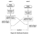
- FIG. 46 Distributed Deadlock, depicts the distributed deadlock problem that can occur in an update anywhere synchronous replication architecture.
- FIG. 47 Application Latency (1) for t>c, depicts the application latency equation for a preferred embodiment of the present invention when t>c.
- FIG. 48 Loss (2) for t>c, is a continuation of FIG. 47 , depicting the application latency equation for a preferred embodiment of the present invention when t>c.
- FIG. 49 Application Latency for t ⁇ c, depicts the application latency equation for a preferred embodiment of the present invention when t ⁇ c.
- FIG. 50 Application Latency L as a Function of Round Trip Time t, depicts the application latency as a function of the replication round trip time, for a preferred embodiment of the present invention.
- FIG. 51 High Level Architecture, depicts the high level process architecture of a preferred embodiment of the present invention.
- FIG. 52 Begin Transaction Processing, depicts the high level process architecture for initiating transaction processing in a preferred embodiment of the present invention.
- FIG. 53 Data Replication, depicts replicating data in a preferred embodiment of the present invention.
- FIG. 54 Communication Request Processing, depicts a process architecture and message flow for commit request processing in a preferred embodiment of the present invention.
- FIG. 55 Communication Request Processing Using Buffer ACKs, depicts a sequence diagram of message flows using buffer acks for commit request processing in a preferred embodiment of the present invention.
- FIG. 56 Communication Request Processing Using Data Update ACKs, depicts a sequence diagram of message flows using data update acks for commit request processing in a preferred embodiment of the present invention.
- FIG. 57 Communication Processing, depicts a process architecture and message flow for commit processing in a preferred embodiment of the present invention.
- FIG. 58 Synchronizing the RTC, depicts a sequence diagram for synchronizing the RTC for an example transaction, in a preferred embodiment of the present invention.
- FIG. 59 Source and Destination Routing, depicts routing transaction steps and/or transaction operations in a preferred embodiment of the present invention.
- FIG. 60 Application Generated RTS, depicts a process architecture and message flow for an application generated RTS (request to send or ready to send), in a preferred embodiment of the present invention.
- FIG. 61 Transaction Registration Latency, depicts the components of the latency that occurs in transaction registration in a preferred embodiment of the present invention.
- FIG. 62 Asynchronous Registration Latency, depicts the components of the latency that occurs in asynchronous transaction registration in a preferred embodiment of the present invention.
- FIG. 63 Communication Latency, depicts a sequence diagram of commit latency in a preferred embodiment of the present invention.
- FIG. 64 Failure Flow Chart, depicts a flow chart of the recovery decision paths when a failure occurs in a preferred embodiment of the present invention.
- FIG. 65 Shows a state diagram showing the state transitions for various events that occur during processing in a preferred embodiment of the present invention.
- FIG. 66 AUDCOLL/AUDRTR Connection, depicts the connection interface across a network for the AUDCOLL and AUDRTR messaging traffic in a preferred embodiment of the present invention.
- FIG. 67 AUDCOLL/AUDRTR Connection with Monitor, depicts the connection interface across a common network for the AUDCOLL and AUDRTR messaging traffic and the interaction each side has with the monitor in a preferred embodiment of the present invention.
- FIG. 68 AUDCOLL/AUDRER Connection with Two Networks, depicts the connection interface across separate networks for the AUDCOLL and AUDRTR messaging traffic and the interaction each side has with the monitor in a preferred embodiment of the present invention.
- FIG. 69 AUDCOLL/AUDRTR Connection with Watchdogs, depicts the connection interface between the AUDCOLL and AUDRTR and the interaction of the monitor when using a watchdog, or quorum, system for monitoring and decision making support.
- FIG. 70 Locking Without Replication, depicts the access to a particular record is managed via locking the record before updating it.
- the diagram shows how one request (the first one) is granted, and the other request (the second one) is delayed until the first one completes.
- FIG. 71 Synchronous Replication Deadlocks, extends the discussion from FIG. 70 into a synchronous replication environment, depicting how local locks can escalate into network deadlocks in a synchronous replication environment in the absence of a lock arbitration approach, such as a global lock manager.
- FIG. 72 Global Lock, depicts how a global lock approach can be used to mitigate the deadlock issues that can otherwise occur in a synchronous replication environment.
- FIG. 73 Global Lock Manager, depicts a process and message flow diagram showing how a global lock manager can be implemented to mitigate the deadlocks that can otherwise occur in a synchronous replication environment in a preferred embodiment of the present invention.
- FIG. 74 Distributed Lock Manager, depicts a process and message flow diagram showing how a distributed lock manager can be implemented to mitigate the deadlocks that can otherwise occur in a synchronous replication environment in a preferred embodiment of the present invention.
- FIG. 75 Replicating an Intelligent Locking Protocol, depicts a sequence diagram showing how replication can be used to implement an intelligent locking protocol.
- FIG. 76 Nondeterministic I/O Ordering, depicts the prior art data consistency and referential integrity problem imposed by non-deterministic I/O ordering in a NonStop audit trail.
- FIG. 77 Shows the prior art data consistency and referential integrity problem imposed by non-deterministic I/O ordering in a NonStop audit trail using a parent/child relationship example.
- FIG. 78 Multiple Collectors, depicts how to scale the audit trail reading to handle higher loads in a preferred embodiment of the present invention by using multiple Collectors, each reading all of the audit trail data (but filtering off the part they are not supposed to replicate).
- FIG. 79 One Trail per Audit Collector, depicts how to scale the audit trail reading to handle higher loads in a preferred embodiment of the present invention using one Collector per audit trail.
- FIG. 80 Multiple Routers, depicts how to scale the routers to handle higher load and add in additional sparing in a preferred embodiment of the present invention.
- FIG. 81 Restart with Multiple Routers, depicts how to restart the replication system and shows DBS allocations when there are multiple routers in a preferred embodiment of the present invention.
- FIG. 82 One Reader, depicts an alternate architecture designed for scaling and load for audit trail reading.
- FIG. 83 Dedicated Readers, MAT Assembles, depicts an alternate architecture designed for scaling and load for audit trail reading.
- FIG. 84 Dedicated Readers, Collector Assembles, depicts an alternate architecture designed for scaling and load for audit trail reading.
- FIG. 85 Scheme Management Architecture, depicts a process architecture showing message flows for managing file and table schemas in a preferred embodiment of the present invention.
- FIG. 86 Retrieving Schemas, depicts a sequence chart showing message flows for managing file and table schemas in a preferred embodiment of the present invention.
- FIG. 87 Single Target Transaction Architecture, depicts allocating transactions across multiple consumers in a preferred embodiment of the present invention.
- FIG. 88 Scaling Single Target Transaction Architecture, depicts scaling for allocating transactions across multiple consumers in a preferred embodiment of the present invention.
- Part 1 of this overview describes the various data replication techniques in use today. It starts with a high-level view of data replication and notes that there are two important types—asynchronous replication and synchronous replication. Both can be used to maintain geographically-separated database copies in synchronism, thus allowing the configuration of systems that will tolerate site disasters with little or no data loss and with near instant recovery.
- Asynchronous replication is discussed first. Its primary advantage is that it is noninvasive to the applications, requiring no modifications and imposing no performance penalties. However, there may be some loss of data following a node failure.
- synchronous replication ensures that either all database changes are made to all database copies across the network or that none are. Therefore, synchronous replication guarantees an RPO (Recovery Point Objective) of zero.
- RPO Recovery Point Objective
- synchronous replication has its own issue, which is that transactions are delayed while transaction completion is assured across the network. This delay increases transaction response times.
- synchronous replication is invasive to the application, the extent of which depends upon the method of synchronous replication used.
- Both asynchronous and synchronous data replication can be used bidirectionally to keep multiple active databases in synchronism with each other. This leads to active/active systems, in which two or more geographically-distributed processing nodes cooperate in the same application. Should a node fail, all that is required is to redirect users or transactions to surviving nodes, resulting in recovery times measured in seconds or less. Thus, RTO (Recovery Time Objective) can be reduced to near zero.
- bidirectional replication adds a new problem; and this is data conflicts.
- a data conflict occurs when two nodes attempt to modify the same data item at the same time. Methods to avoid or to resolve data conflicts are presented.
- Part 1 compares the various technologies used today to provide backup data processing facilities to ensure business continuity in the face of a disaster. These technologies are compared graphically on a business continuity continuum.
- data replication is a technique for keeping multiple database copies in synchronism.
- the source database hosted by the source node also called the originating node
- the target database hosted by the target node also called the destination node.
- a target node can also be a source node (as is the case in bidirectional replication), but for simplicity case, only two nodes are discussed in this description.
- the two nodes comprise the data processing system.
- the two nodes can be local to each other, or remote from each other (when used for business continuity/disaster tolerance purposes, the two nodes are generally remote from each other). In some special cases, the two nodes are actually physically resident on the same node.
- the application is distinct from the replication system.
- the replication system (or parts thereof) are embedded into the application (the application provides some of the services, or steps, that the replication system needs, such as the gathering of the transaction steps or operations that need to be replicated).
- the target database is a current and consistent copy of the source database and can even be used by applications running on the target node.
- the target database can also be a source database being changed by its local applications, with these changes being replicated to other database copies.
- a common technique for data replication is to use a data replication engine, as shown in FIG. 2 .
- Many off-the-shelf data replication engines are available today to replicate data between any two databases, even if they are different.
- database synchronization must be qualified. Without further explanation, one would assume that the database copies are perfectly synchronized and are exact copies of each other at any point in time. This, in fact, can be accomplished with a technique known as synchronous replication. However, with synchronous replication, the modifying application must wait for all of the remote copies of the database to confirm that they have successfully made a change in order to ensure that the database copies are, indeed, kept in synchronism. This has the effect of delaying the completion of transactions, thus slowing transaction response time. The delay is known as application latency.
- Asynchronous replication With asynchronous replication, changes are replicated after they have been made to the source database and without any interaction with the application.
- Asynchronous replication comes with its own set of issues, primarily the fact that the database copies are not exactly in synchronism.
- the target database copies can lag the source database copies by times measured anywhere from milliseconds to seconds. This delay is known as replication latency.
- Replication latency can lead to data loss following a node failure and to database corruption due to changes being made simultaneously to different database copies within the application network.
- An asynchronous data replication engine is completely transparent to (decoupled from) the applications running in the source node. It does not interact with the applications at all. Rather, as shown in FIG. 3 , an Extractor picks up changes made to the source database from a change queue and sends them after-the-fact to the Applier at the target database. Changes are made to the target database copy by the Applier somewhat later than they were made to the source database. The result is that the databases are kept in synchronism, but the target database copy lags the source database by a short interval, that is, the replication latency of the data replication engine.
- the Extractor can be configured to buffer many changes before transmitting them as a large block to the Applier in the target node. In this way, many fewer messages need to be transmitted as compared to having to transmit each change one at a time as a small message.
- the source database and the target database can be resident on the same node, or can each be resident on a different node.
- the target node/database is remote from the source (or originating) node/database by a distance far enough to negate or minimize the effects of regional disasters (e.g., hurricanes, tornados, power outages in the power grid, etc).
- the data replication engine must be given the changes made to the source database. This is done via a change queue, which as its name implies holds a queue of changes that have been made to the source database.
- the replication engine reads the changes from the change queue via its Extractor process, which sends them over the communication channel to the target database. There the changes are received by the replication engine's Applier process, which applies them to the target database copy.
- the change queue should be a persistent queue to protect the replication engine from hardware and software faults. If a failure of some sort should cause replication to fail, changes that have not yet been sent must still be available when replication is restored. For this reason, the change queue is usually disk-resident so that change entries survive despite a failure of any kind.
- the change queue can be implemented in many ways:
- Asynchronous replication can be heterogeneous with today's replication engine products. They can replicate between diverse databases whether they be different versions from the same vendor, databases from different vendors, or even databases with different structures, such as from HP's NonStop Enscribe file system to an Oracle relational database. Required format changes from one database structure to another are provided by rules that can be established within the replication engines themselves.
- a very important characteristic of asynchronous replication is that there is a delay from the time that a change is made to the source database to the time that it is made to the target database. Depending upon the replication engine, this replication latency can range from milliseconds to seconds or beyond.
- Replication latency causes several problems that may have to be dealt with, as described later. The shorter the replication latency, the less severe are these problems. Therefore, it is important to select a replication engine that is very fast—fast enough to meet the requirements of the application. Replication latency is controlled by several factors, some within the control of the replication engine and some not.
- the delay factors in replication latency include:
- replication latency is data loss following a failure of the source node. Any changes that were in the replication pipeline and that have not made it to the Applier in the target node will be lost. As shown in FIG. 4 , they include changes that at the time of failure have not yet made it to the change queue, those that are still in the change queue, and those that have been read from the change queue but are still waiting in the communication buffer for transmission to the target node.
- RPO Recovery Point Objective
- RPO is a measure of an application's tolerance to data loss. For instance, a company may decide that it can lose up to an hour's worth of data. Alternatively, it may decide that it can only lose one second's worth of data or that the application must lose no data at all. The amount of data loss that is tolerable is the RPO for that application.
- RPO replication latency
- the replication latency of the replication channel must be less than the RPO requirement for the application.
- Today's asynchronous replication engines can achieve replication latencies measured in the tens of milliseconds. If RPO is zero (such as in a stock trading system), this cannot be achieved via asynchronous replication. This is the realm of synchronous replication, described later.
- Referential integrity refers to the correctness of the database. To satisfy referential integrity, every child row (like an invoice detail line) must have its parent (like the invoice header) resident in the database. Most relational databases provide referential integrity checking. If a database change violates referential integrity, it can be rejected.
- replicated changes must be applied in such an order so as to satisfy referential integrity. Providing that the source database satisfies referential integrity, most replication engines will apply all changes in the same order to the target database as they were applied to the source database. Therefore, referential integrity is preserved.
- Some high-performance replication engines can provide multiple replication threads to increase capacity. In such cases, changes are not necessarily guaranteed to arrive at the target in the proper order. These replication engines may have special features that allow them to reorder the changes so that they are applied properly.
- the multiple replication threads can be implemented thru a variety of methods, and several methods can be in use at the same time.
- there are a number (typically more than one) of appliers the processes that apply the database changes to the database). These appliers can be resident at the target node, the source node, or a combination thereof.
- Having one or more than one applier is often referred to as a “plurality of appliers”, and each often represents a separate replication “thread”.
- the appliers can be implemented as separate processes (separate instances of processes), each typically with one execution thread.
- the appliers can be resident at the target node, as well as at the source, or originating, node, or both.
- the appliers are generally located at the target to improve the efficiency of their target database interaction.
- the multiple replication threads can be implemented as one or more execution “threads” in each process (this is sometimes referred to as a multi-threaded process).
- the replication engine can thus consist of a single multi-threaded process, a number of processes each with one or more execution threads, or any combination thereof.
- the events that are replicated by the replication engine are usually DML I/O events (such as insert, update, and delete operations), or DDL events (such as create table, drop table, alter table, etc).
- DML I/O events such as insert, update, and delete operations
- DDL events such as create table, drop table, alter table, etc.
- the events are grouped into logical entities called “transactions”.
- the events inside a transaction are often referred to as “transaction steps” or “transaction operations”.
- the events are sometimes called steps when they affect zero or one record or row in the database (e.g., delete the account record for account ID 12345).
- the events are called “operations” or “statements” when they affect zero, 1, or more than one record or row (e.g., delete all of the account records with a negative balance).
- Transactions usually adhere to the ACID properties (atomic, consistent, isolated, durable), and are applied as a single unit of work (either all changes/events in the transaction are applied, or none are). Transactions hence can consist of individual transaction steps, transaction operations, or a combination thereof.
- the real strength that asynchronous replication brings is disaster tolerance. Since the target node can be any distance—even thousands of miles—from the source node, redundant data centers can be established well beyond the distance that would be impacted by any single disaster such as an earthquake, hurricane, flood, or terrorist attack. The only penalty as distance becomes greater is an increase in replication latency due to communication channel transit time.
- Synchronous replication solves the asynchronous replication problem of data loss following a node failure. With synchronous replication, no change is made to any database copy unless that change can be applied to all database copies. Therefore, should a node or the network fail, no data is lost. Synchronous replication can satisfy RPOs (Recovery Point Objectives) of zero.
- a synchronous replication engine first acquires locks on all copies of a data item to be changed. Only after it has acquired all locks will it authorize the change. At that time, each database copy will commit the change and will release the lock on its local copy of the data item.
- synchronous replication is usually done at the transaction level.
- a transaction is first started on each database copy.
- the source transaction manager asks each database copy if it is ready to commit all of the changes making up the transaction. This is the first phase of a two-phase commit process. If a database copy is holding locks on all of the data items, it replies positively. Should the source transaction manager receive positive responses from all of the database copies, it issues a commit directive (phase 2 of the commit process); and all database copies commit their changes and release their locks. Should any database copy indicate that it cannot commit the transaction, the transaction is aborted. Pending changes, if any, are rolled back; and all locks are released in all database copies.
- the transaction is either applied to all database copies, or it is applied to none of them. Consequently, should a system fail, no data is lost except transactions that were in progress at the time of the failure and had not yet been committed. Their associated changes will appear in none of the database copies.
- Network transactions are the easiest to understand. All of the copies of the data items to be changed are simply included in the scope of the transaction, as shown in FIG. 5 .
- the application first begins a transaction on each database copy to be included in the transaction (1). It then identifies and captures and sends the transaction changes to each database copy (2) followed by a commit command to each copy (3).
- a common one is for the application to use an intercept library to capture the transaction steps or operations to be replicated.
- the transaction managers in the database copies will cooperate to either commit the transaction across all database copies or to abort it.
- Coordinated commits use an asynchronous replication engine to move changes from the source node to the target node.
- a simplified view of the coordinated commit process is shown in FIG. 6 .
- the asynchronous replication engine joins each transaction as it is begun (1).
- the begin directive can either be sent directly to the target database over the replication channel, or it can be implicit in the first change received by the target database for that transaction. In either case, a new transaction is initiated at the target database and is independent of the source's transaction.
- UML Unified Modeling Language
- the changes are made to the source database by the transaction manager (2a).
- the transaction manager also puts the changes into the change queue (2b), from where they are replicated to the target database via the replication engine (2c).
- the target node locks are acquired on the data items to be changed; and the changes are either held or are tentatively applied pending a commit directive (2d).
- a “ready to commit?” query is sent down the replication channel by the transaction manager (3a, 3b). By sending this query via the replication channel, it is guaranteed that it will arrive at the target after all changes have been received by the target database.
- the replication engine checks to ensure that locks are being held on all data items to be changed, and if so it returns a “ready to commit” response to the transaction manager on the source node (4). If the response is affirmative, the source transaction manager issues a commit directive to the source database (5). It also inserts a commit directive into the change queue (5a), from where it is replicated to the target database (5b). At the target database, the changes are made permanently; and the locks are released (5c). Also at this time, the transaction manager informs the application that the transaction has committed (5d).
- the transaction is aborted. All pending changes are rolled back on all of the database copies, and the transaction has no effect.
- the transactions at the source node and at the target node are different. This allows the target transaction to proceed independently of that at the source node without affecting the source node until commit time. At that time, the coordinated commit facility ensures that both transactions can commit successfully before committing either of them. If one transaction cannot compete successfully, then both are aborted.
- the transaction can still complete on the source system. Transaction processing can continue in the presence of the failed system by simply excluding it from commit voting. This is in contrast to network transactions, in which a single transaction spans multiple nodes. If a node fails, transaction processing cannot continue without reconfiguring the applications to exclude the failed node from further transactions.
- DLM Distributed lock management
- the actual change data is sent to the target node via asynchronous replication (2d) so that the propagation of the data changes across the network is transparent to the application.
- the application commits the transaction (3, 3a)
- the commit can be immediately replicated to the target database (3b) because DLM knows that the target database is holding all required locks.
- Distributed lock management has substantially the same application-delay characteristics as network transactions since each lock requires a network round-trip time to acquire a lock. Therefore, it is just as sensitive to communication latency as are network transactions.
- DLM's use of the communication channel has similarities to both network transactions and coordinated commits. Like network transactions, many small messages must be sent as each lock is individually requested. This leads to network inefficiencies. However, like coordinated commits, DLM makes more efficient use of the communication channel when propagating data to the target node since it uses asynchronous replication for this purpose. A large number of changes can be buffered and sent in a single communication block.
- Distributed lock management can, in principle, be implemented with no application modifications. However, as a general rule, the disk drivers (or database management system) must support distributed locks, as described above.
- Recovery from a node failure is substantially the same as that for coordinated commits.
- Synchronous replication solves the asynchronous problem of data loss following a source node failure.
- a transaction is either committed across all nodes in the application network, or it affects none of them.
- An application using synchronous replication is delayed as it is ensured that the transaction will commit on all remote databases.
- the transaction is also delayed as each change is applied to all of the remote databases. These delays increase transaction response time. This delay is known as application latency.
- application latency The effects of application latency are different for different synchronous replication techniques. As discussed below, the result is that network transactions or distributed lock management might be better for campus networks and small transactions; but coordinated commits are decidedly better for longer-distance networks and/or large transactions.
- a network transaction requires two communication channel round trips for each update—one to read the row prior to modifying it and one to rewrite the modified row.
- the two-phase commit process requires an additional two round trips.
- the begin transaction command may require an extra round trip if it is not implicit in the first update.
- FIG. 9 part a) illustrates the network transaction application latency for a transaction that has four updates plus a commit. Ten communication round trips are required to execute this transaction.
- the application latency for coordinated commits is quite different, as shown in FIG. 9 , part b.
- the number of updates in the transaction does not matter since they are replicated asynchronously and have no impact on the application. It is only at commit time that the application must wait to determine that all nodes that have joined the transaction are ready to commit.
- a “ready to commit?” query is sent to the target node via the replication channel.
- This query must be replicated rather than being sent directly to the target node over the communication channel to ensure that it arrives at the target node after the last update has arrived. Therefore, it will take a time equal to the replication latency interval plus a one-way trip over the communication channel for the target node to receive the query.
- the target node If the target node is ready to commit the transaction (that is, it has acquired locks on all data items to be updated and has safe-stored or tentatively applied the updates), it replies in the affirmative with a “ready to commit” response. At this time, the source node can issue the commit directive and can inform the application that the transaction has been committed.
- the application must wait for a time equal to the replication latency of the replication engine plus one communication channel round trip before the commit directive is issued. This is the application latency associated with coordinated commits.
- the application latency associated with DLM is a combination of that associated with both network transactions and coordinated commits.
- the application must wait for one communication channel round trip for each update in order to acquire the locks on the data items to be updated. It then must wait a replication latency time plus another channel round-trip time to determine that the target is ready to commit.
- DLM's application latency is a replication latency interval plus a number of communication channel round trips equal to the number of updates plus one. Its application latency may or not be greater than that for network transactions, but it will always be greater than the coordinated commit application latency.
- Case 1 there are two nodes separated by 100 miles.
- the round-trip communication latency is two milliseconds.
- the two nodes are on the opposite coasts of the United States, separated by 2,500 miles.
- the round-trip communication latency for this case is 50 milliseconds.
- the replication latency of the data replication engine is 40 milliseconds.
- Table 1 shows the application latency for network transactions, coordinated commits, and distributed lock management for each of these cases using a transaction comprising four updates.
- network transactions For the shorter distance of 100 miles, network transactions impose an application latency of 20 msec. compared to 42 milliseconds for coordinated commits. Therefore, for shorter distances and small transactions, network transactions may be the preferred synchronous replication technique.
- the tolerance to node failure is the same for synchronous replication as it is for asynchronous replication.
- the system is down only if all of its spare nodes plus one more have failed.
- the achievement of disaster tolerance depends upon separating the nodes of an application network by distances that will ensure that no single disaster will take down more than one node.
- Disasters include natural disasters such as earthquakes, hurricanes, and floods as well as man-made disasters such as civil unrest and terrorist attacks.
- Application latency can limit the distance that nodes can be separated, thus compromising their tolerance to disasters. This is especially true if network transactions or distributed lock management is used.
- synchronous replication is performed using the coordinated commit approach.
- each of the other synchronous replication approaches, techniques, or architectures e.g., dual writes or distributed lock management
- asynchronous and synchronous data replication techniques have been described as being useful for keeping a target database in synchronism with a source database.
- Data replication is a very useful technique to keep an active system and its backup system synchronized so that the backup system can continue to provide data processing services should the active system fail.
- Such replication is called unidirectional replication since replication is done only in one direction—from the active system to the standby system.
- nodes are peers; and both (or all) may be actively processing transactions or queries. This leads to the concept of active/active systems or sizzling-hot standby systems, topics which are discussed later.
- bidirectional replication An important example of bidirectional replication is an active/active system in which an application is running on multiple nodes in an application network. Each node has its own copy of the application database, and these database copies must be kept in synchronism. When a change is made to one database copy, that change must immediately be reflected in all database copies. This synchronization may be accomplished with either asynchronous or synchronous replication.
- a key advantage of active/active systems is that recovery from a node failure can be accomplished in seconds or less, meaning that very fast RTOs (Recovery Time Objectives) can be met. Active/active systems can satisfy RTOs of near zero. In addition, if synchronous replication is used, an RPO of zero can be satisfied,
- bidirectional data replication This is accomplished by bidirectional data replication.
- each node in the application network can be making changes to its local copy of the database. When a change is made to one database copy, it is replicated to all other database copies in the application network.
- Bidirectional replication is generally implemented by configuring a separate replication engine for each direction, as shown in FIG. 10 .
- Bidirectional replication brings with it its own set of issues. These include ping-ponging and data conflicts.
- Changes made to a source database are entered into a change queue for forwarding to the remote target database. If provisions are not otherwise made, changes replicated to the target database will likewise be entered into its change queue and will be sent back to the source database, as shown in FIG. 11 . Changes will circulate endlessly between the two databases, a situation known as “ping-ponging.”
- Any replication engine that is to be used in a bidirectional mode must protect itself against data oscillation (data ping-ponging).
- the application running in Node 1 is trying to change Row A to a value of 3.
- the application in Node 2 is trying at the same time to change the value of Row A in its database copy to a value of 6.
- Node 1's replication engine dutifully replicates the value of 3 to Node 2, where the change overwrites the original change to a value of 6 made by Node 2's application.
- Node 2's replication engine replicates the change made by Node 2's application to Node 1, changing its value from 3 to 6.
- Row A in Node 1 now reflects the value written by the Node 2 application, and vice versa. Both databases are different, and both are wrong.
- partitioning If the application permits, it can be architected to avoid data collisions.
- One technique is to use partitioning.
- the database is partitioned so that each partition is owned by a specific node in the application network. Only the owning node can change its partition. Its changes are replicated to all of the other nodes so that each node has a complete and current copy of the database, but data collisions cannot occur.
- the database can be partitioned. For instance, as shown in FIG. 13 , all customers whose names start with A through M are in one partition; and all customers whose names begin with N through Z are in another partition. Node 1 owns the A-M partition, and only it can apply changes to that partition. All other changes are made by Node 2, which owns the N-Z partition. If one node receives a change for a partition that it does not own, that change must be sent to the owning node.
- Row A begins with a value of 10.
- Node 1 adds 2 to Row A, and the operation “+2” is replicated to Node 2.
- Node 2 adds 5 to Row A; and the operation “+5” is replicated to Node 1. Both nodes apply both operations, leaving the value of Row A at 17, which is correct.
- a data collision can be detected by comparing the before-images of the source database and the target database. Using this method, each replicated change is accompanied by the source node's before-image of the row that is being changed. If this before-image does not match that of the target node, a collision has occurred. Row versions or time stamps may also be used to accomplish the same result.
- One way to resolve data collisions is by data content. For instance, the later change may be accepted and the earlier change rejected.
- Another technique is to designate one node in the application network as the master node and the others as slaves, as shown in FIG. 15 . All changes are made by the master node and replicated to the slave nodes. If a slave change collides with a master change, the master wins. If two slave changes collide, the master decides the winner, perhaps by using data content. In any event, only the single winning change is replicated to the slaves.
- slave nodes can apply their changes locally and can replicate them to the master.
- the master resolves any data collisions and replicates the resulting changes to all slaves, including the slave that originated the change.
- all changes are made locally at a node, improving performance.
- this is at the expense of doubling the replication latency between nodes as a change propagates from one slave to the master and then back all slaves. The result is a tradeoff between performance and the rate of data collisions.
- a variation of the master/slave technique is a hierarchical configuration in which each node is assigned a priority. In the event of a collision, the node with the higher priority wins.
- asynchronous replication engines can be configured to resolve data collisions via embedded rules. If a collision cannot be automatically resolved, it may be reviewed and then corrected manually.
- Data collisions can be avoided by using synchronous replication since a data item can only be modified by one node at a time. This is because a node must acquire locks on all copies of the data item across the application network before it can modify the data item.
- deadlocks are always a problem.
- an application thread In order to properly synchronize changes, an application thread must first acquire a lock on a data item that it wants to change. The lock prevents another application thread from trying to modify the same data item at the same time, which would lead to an indeterminate result. Once the application thread has made its change, it then releases the lock so that other application threads have access to that data item.
- Deadlocks can occur if care is not taken in how locks are acquired. For instance, consider two application threads that need to lock rows A and B. Thread 1 is designed to lock row A first, followed by row B. Thread 2 locks these same two data items but in the opposite order. If both threads want to change these rows at the same time, Thread 1 will lock row A while Thread 2 will lock row B. Thread 1 cannot now acquire a lock on row B, and Thread 2 cannot acquire a lock on row A. A deadlock has occurred. A standard way to resolve such deadlocks is for one or both threads to time out, release their locks, and try again later at a random time.
- lock latency time is the one-way communication channel propagation time.
- the lock latency time is the one-way communication time plus the replication latency of the replication engine.
- the lock latency problem is illustrated in FIG. 16 .
- applications running in each node are using an ILP, and both applications want to lock row A nearly simultaneously (within the lock-latency interval). They will each be successful in acquiring the lock on their local copies of row A. However, when they attempt to acquire a lock on the remote copy of that row, they cannot. The two applications are now deadlocked since neither can get the lock on its remote copy.
- Another technique for avoiding distributed deadlocks is to use an ILP with a global mutex.
- one node in the application network is designated the lock master.
- the lock master holds locks that must be acquired by any application in the network according to an ILP before that application can proceed. For instance, a lock master may hold locks on invoice headers. Before modifying an invoice, an application must obtain a lock on that invoice header from the lock master. Only then can it modify the invoice's detail lines. Should the lock master fail, one of the other nodes must be promoted to lock master.
- Bidirectional replication assumes that all nodes in the application network are operational and are communicating with each other. But what happens if a network failure isolates some nodes from the other nodes so that changes cannot be replicated between the isolated groups?
- split-brain mode ( FIG. 17 ). Each set of nodes is allowed to continue processing independently from the other set. Changes are queued; and when the network is restored, the change queues are drained to update the split databases. In this case, data collisions are bound to occur unless the database is partitioned. They must be identified and resolved when the network is restored and replication is resumed. Data collision identification and resolution have been described earlier in the subsection entitled Data Conflicts.
- Another solution is to take one of the isolated groups out of service. This may be done automatically using quorum techniques developed for clusters, or it may be done manually. Typically, if there are multiple nodes in the network, the larger group is kept in service; and the smaller group is taken down. Either some noncritical load must be shed, or there must be enough processing capacity in the surviving group to handle the transaction load.
- split-brain mode must be avoided.
- One of the isolated sets of nodes must be taken out of service until the network is restored.
- Bidirectional replication leads to a particularly powerful system configuration—an active/active system.
- An active/active system is a geographically-dispersed network of independent processing nodes cooperating in a common application. Should a node fail, all that needs to be done is to switch over that node's users to a surviving node. Recovery is in subseconds to seconds.
- Bidirectional replication provides the mechanism to keep these local copies synchronized. As shown earlier in FIG. 10 , whenever one node makes a change to its local database, that change is replicated to all of the remote database copies. Therefore, the application running in each node of the active/active system has immediate access to an up-to-date (or nearly up-to-date) local copy of the application database.
- Active/active systems provide many advantages over active/backup systems:
- RPO Recovery Point Objective
- RPO is expressed in terms of time and may vary with the application. In some cases, a company may be able to tolerate the loss of days of data for a particular application. More likely is that the loss of more than a few hours of data represents an extreme hardship. In more critical applications, it may be required that data loss be limited to minutes or even seconds. In very critical applications such as security trading systems, no loss of data can be tolerated.
- RTO Recovery Time Objective
- RTO varies by application. Some noncritical applications may be able to be down for days without seriously affecting a company's operations. Typical applications can withstand a few hours of downtime. Critical applications may have to be restored in minutes or seconds. Applications that affect life or property may be required to never be down (at least, hardly ever).
- FIG. 18 shows the relationship between RPO and RTO.
- steps are taken to recover processing. This may entail repairing the downed system, or it may entail switching over to a backup system.
- the time from the point of failure to the time of recovery must be less than the RTO specified for the application.
- RPO specifies the maximum amount of time between a backup of the database (full or incremental) and the point of failure.
- RTO specifies the maximum amount of time from a system failure to its recovery. For instance, if RPO is four hours, database backups must be taken more frequently than every four hours. If RTO is ten minutes, a second backup system ready to go is certainly needed.
- Data replication technology allows systems to be configured to meet any required RPO and RTO, as is evidenced by active/active configurations described earlier. Certainly, as these times get shorter, system costs may escalate (though not always, as more sophisticated configurations may be able to achieve shorter RPOs and RTOs with the same equipment). These additional system costs must be weighed against the costs of lost data and downtime, which in many critical applications may be quite significant or which, in some industries, may violate governmental regulations.
- Database backup techniques bear directly on both RPO and RTO. Look at classic database backup methodologies and how these paradigms have shifted toward data replication for increased business continuity.
- Disaster recovery is the ability to recover from a disaster.
- Disaster tolerance is the ability to be unaffected by a disaster.
- a system can be configured to meet either standard. Disaster recovery configurations will be discussed first.
- the backup tapes It is good practice to store the magnetic tapes offsite for security purposes. Should the active system fail, the backup tapes must be retrieved from the storage vault and brought to the standby site. There, the last full backup must be read from tape and loaded onto the backup system, followed in sequence by each of the later incremental backups. (In this case, the backup system is called a cold standby since it has no applications loaded nor does it have a database mounted.)
- Magnetic tape is suitable if hours or days of data can be lost (RPO of hours to days) and if recovery time measured in hours to days is satisfactory (RTO of hours to days).
- Virtual tape replaces magnetic tape with disk images ( FIG. 20 ). Rather than having to mount and catalog hundreds of tapes, virtual tape maintains a backup image of the application database on disk at the backup site. Full and incremental backups of the database are still taken; but instead of writing these backups to magnetic tape, they are sent via a communication facility to disk storage at the backup site.
- Clusters represent a formalized methodology to provide redundancy. They are supported by a plethora of off-the-shelf products available today.
- a cluster comprises two or more processing nodes, each with a physical connection to a redundant storage subsystem such as a RAID array ( FIG. 21 ).
- An application can run on any one node in the cluster, and that node can be backed up by one or more other nodes in the cluster.
- RTO Recovery times
- both RTO and RPO can be compromised if database corruption occurs during a node failure.
- Database corruption may occur if the failure interrupts a sequence of write operations that taken together comprise a logical operation. Block splits and index updates are examples of such operations.
- the cluster Immediately upon takeover, the cluster must check the database for such corruption. If corruption is found, some data may have been lost, violating a zero RPO.
- the repair of the database may take a significant amount of time, resulting in a recovery time that may exceed the RTO.
- clusters One limitation of clusters is that the nodes must all be collocated. Therefore, a cluster is not inherently disaster tolerant. It can be taken down by a site disaster and is therefore not suitable for business continuity. To provide disaster recovery, an equivalent standby cluster must be configured at a remote site and kept synchronized with unidirectional replication. Used in this way, clusters have the same disaster recovery characteristics as active/backup systems using unidirectional replication, described next.
- Data replication is the new paradigm for database backup. It can provide zero data loss (satisfying an RPO of zero); and properly configured, it can provide nearly instantaneous recovery (an RTO of almost zero).
- Unidirectional data replication is the simplest form of the data replication architecture ( FIG. 22 ).
- An active node processes all transactions, and the changes that it makes to its database are replicated to a remote standby node. Therefore, the two databases are in (or are nearly in) synchronization. Should the active node fail, no data or only a small amount of data will be lost. If asynchronous replication is used, only the data in the replication pipeline at the time of failure will be lost, thus supporting subsecond RPOs. If synchronous replication is used, no data will be lost following an active node failure (RPO of zero).
- Applications may be up and running in read-only mode in the standby node so that the standby database may be actively used for query and reporting purposes (this is called a “hot standby”). Should the active node fail, the applications at the backup node can remount the database for read/write access and can take over the role of the original active node. This typically takes only a few minutes, leading to RTOs measured in minutes.
- data replication allows the active node and its backup to be separated by an arbitrary distance. Therefore, the system can be configured so that no common disaster can take down both the active and backup nodes.
- Disaster tolerance requires that there be a backup node that can take over in subseconds or seconds in the event of an active-node failure. Two data replication configurations are described that can satisfy this requirement.
- a sizzling-hot standby is similar to a standby node using unidirectional replication, as described above, except that it is immediately ready to start processing transactions ( FIG. 23 ). This means that it has its local copy of the application database already open for read/write access. Using data replication, it can do this because its local database is synchronized with the active database and is completely consistent and accurate. In fact, except for the fact that the active node would be unaware of the standby's database changes, the standby node could be actively processing transactions (an excellent example of another type of sizzling-hot standby configuration is an HP NonStop checkpointed process pair, except that process state is replicated rather than data).
- the sizzling-hot standby configuration has another big advantage over the disaster recovery systems described above, and that is the absence of failover faults.
- the standby system In the systems previously described, the standby system is not actively involved in the application. Therefore, it is not known whether it is really operational. Should a failover attempt be made to a nonfunctioning backup system, the application is down. This is known as a failover fault.
- the sizzling-hot standby can be configured with reverse replication up and running so that it has a backup as soon as the old primary node is recovered.
- the standby With reverse replication enabled, the standby will be queuing the changes that it is making to its copy of the database so that the failed node can be resynchronized upon recovery.
- This configuration can achieve a zero RPO if synchronous replication is used or RPOs measured in milliseconds if asynchronous replication is used. If failover is automatic, RTOs measured in subseconds or seconds can often be satisfied.
- a sizzling-hot standby with reverse replication enabled is similar in many respects to a two-node active/active system, described below, except that only one node is actively processing change transactions (though the backup node can be processing queries). It has applicability if data collisions are to be avoided. It can also be used to achieve many of the active/active benefits described next if the application cannot be made active/active ready (for instance, if all events must be processed in exact sequence, such as in a process control application).
- An active/active configuration takes the sizzling-hot standby configuration one step further. All nodes in an active/active network may be simultaneously processing transactions for the same application using their local copies of the application database ( FIG. 24 ). Bidirectional data replication is configured between each node pair so that any change that a node makes to its local copy of the application database is immediately replicated to the other nodes in the application network.
- sizzling-hot standbys do not address the maintainability and performance benefits of active/active systems (except that queries can be run on the backup node), they do provide all of the availability benefits.
- FIG. 25 This diagram plots RPO versus RTO and shows where each methodology fits.
- the horizontal axis shows improving RTO as it trends toward zero recovery time, and the vertical axis shows improving RPO as it trends toward zero data loss following a node failure. System continuity increases as shown.
- the magnetic tape approach has the lowest availability. Its RPO is the greatest as is its RTO—hours to days for both. Virtual tape is a significant advantage over magnetic tape, reducing RPO and RTO to hours, not days.
- recovery time can be in minutes.
- RPO can be zero if synchronous replication is used, or it can be measured in milliseconds if asynchronous replication is used.
- RTO Recovery times
- RPO data loss
- Sizzling-hot standby systems provide many of the advantages of active/active systems. Note that these systems are not scalable, they cannot be load balanced, they cannot provide data locality, and they make use of only half of the configured capacity. However, they do provide all of the extensive active/active availability advantages for applications that cannot, for some reason, run in a truly active/active environment.
- clusters do not inherently provide disaster tolerance.
- a remote standby cluster must be configured and kept synchronized via replication. Therefore, a cluster has business continuity characteristics similar to those of asynchronous unidirectional replication.
- FIG. 26 Shown in this figure are typical RPOs and RTOs ( FIG. 26 , part a), typical configurations ( FIG. 26 , part b), and typical applications ( FIG. 26 , part c) for the four combinations of unidirectional and bidirectional asynchronous and synchronous replication. Representative characteristics for systems implemented with each of these are as follows:
- Shadowbase Plus SR from Gravic, Inc., Malvern, Pa. (www.gravic.com), is a synchronous replication engine using coordinated commits. Compared to other synchronous replication technologies, Shadowbase Plus SR requires no changes to applications and can provide synchronous replication over the hundreds or thousands of miles often required for disaster tolerance.
- Part 2 describes the Shadowbase Plus SR architecture and its procedures for synchronous replication.
- the various software processes comprising Shadowbase Plus SR are described, and the flow of data and transaction control through these processes is illustrated.
- Shadowbase Plus SR imposes a delay on the completion of the source's transactions while it ensures that transactions are able to be completed on all database copies in the application network. This delay is known as application latency.
- the coordinated commit method used by Shadowbase Plus SR is much less affected by communication delays as are other synchronous replication technologies.
- Part 2 describes the components of Shadowbase Plus SR's application latency and the impact of application latency on applications.
- the Shadowbase Replication Suite comprises a set of products that support unidirectional and bidirectional data replication. Both asynchronous replication and synchronous replication are supported.
- the Shadowbase products include:
- the Shadowbase products support not only HP NonStop server databases but also open server databases (such as MySQL, Oracle, and Sybase) as well. Replication with the Shadowbase replication engines as well as target database loading with Shadowbase's online loaders is heterogeneous.
- the source and target databases can be from different vendors. They can also represent different architectures such as relational databases and flat-file systems.
- Shadowbase Plus SR synchronous data replication engine
- the Shadowbase asynchronous data replication engine uses process-to-process replication to move data from a source database to a target database. Since there are no disk-queuing points introduced by Shadowbase, replication is highly efficient; and replication latency is minimized.
- Shadowbase replication engine has been used for several decades in hundreds of installations. It is, therefore, a very mature product.
- Shadowbase data replication engine for an HP NonStop server
- the replication engine's architecture is shown in FIG. 27 .
- the heart of the replication engine is a Collector process running on the source node and a Consumer process running on the target node.
- the source and target nodes can be on the same node.
- Shadowbase provides the AUDCOM process for control and the AUDMON process for monitoring.
- TMF Transaction Monitoring Facility
- the Shadowbase Collector process uses this library to read the source database changes as they are logged by TMF. It buffers these changes and sends them in a communication block to the Shadowbase Consumer running in the target node. Communication between the source and target nodes may be either via NonStop EXPAND or via TCP/IP (If TCP/IP is used, Shadowbase adds a source-side Consumer process that supports TCP/IP communications with the target-side Consumer. The Collector sends changes to the source-side Consumer for transmission to the target-side Consumer, which will apply the changes to the target database).
- the first change received by the Consumer for a source transaction is used to start an independent transaction on the target node. This change and all further changes for this transaction are applied tentatively to the target database until it is notified that the transaction has either been committed or has been aborted at the source node. If the transaction has been committed at the source database, the Consumer will commit it at the target database. Conversely, if the transaction was aborted at the source database, the Consumer will not apply the transaction's changes to the target database.
- Shadowbase replication engine is very efficient and minimizes the replication latency of the data replication engine.
- Shadowbase can support multiple Collectors and Consumers to improve performance. If multiple Collectors are used, each transaction is typically handled by only one Collector (Transactions, and the events inside them, can be spread across one, or multiple, Collectors and/or Consumers; this aids scaling for volume. However, to guarantee that events for the same data set are applied to the target database in the proper order, a particular data set is generally assigned to a specific Collector/Consumer replication thread). If multiple Consumers are used, each table or file (or subset thereof) is typically handled by only one Consumer. In this way, it is guaranteed that changes made to any file or table (or key range thereof) are correctly sequenced.
- a unidirectional Shadowbase asynchronous replication engine is useful to maintain synchronization of a backup database with its primary database.
- the backup system is idle so far as update processing is concerned.
- Shadowbase guarantees that the target database, though delayed by the replication latency, is always a consistent copy of the source database.
- both nodes can be actively processing transactions since each has a reasonably up-to-date copy of the application database (typically, up-to-date within milliseconds). This is the realm of active/active systems, which were described in Part 1.
- bidirectional replication is accomplished simply by using two replication engines, one in each direction.
- the Shadowbase bidirectional architecture is shown in FIG. 28 . It comprises two independent unidirectional data replication engines, each replicating from one node to the other. As changes are made by application A to its database A, these changes are captured in the TMF audit trail on node A. Collector A reads these changes and sends them to Consumer A on the target node, which applies them to database B on node B. Likewise, changes made to database B by application B are replicated to node A by Collector B and Consumer B.
- Shadowbase provides its own transaction ID log with each data replication engine (transaction ID logs A and B in the FIG. 28 ). Whenever a Consumer applies a change to its target database, it notes that change in its transaction ID log. The change recorded in the target node's audit trail is marked as a replicated change. In this way, the Collector reading that audit trail will know not to replicate the change. This anti ping-ponging feature creates the one connection between the two data replication engines.
- a data collision occurs if nearly simultaneous changes are made by each node to the same data item. Nearly simultaneous means within the replication-latency interval. Should this happen, both changes will be replicated to the other node and will overwrite the original change made at that node. Now, both databases are different; and both are wrong.
- Shadowbase asynchronous data replication engine supports collision-avoidance architectures. If collisions cannot be avoided, Shadowbase provides the mechanisms necessary for detecting and resolving data collisions.
- FIG. 28 illustrates bidirectional replication between two nodes in an active/active system. However, there is no limit to the number of nodes that can cooperate in such a system. All that needs to be done is to provide bidirectional replication capabilities between each of the nodes in the application network.
- Shadowbase Plus SR meets is to provide a reliable synchronous replication engine with low application latency. Its design supports several important attributes:
- Shadowbase Plus SR initially supports HP NonStop Enscribe and SQL/MP databases as both sources and targets. Future releases will support HP NonStop SQL/MX native tables and a variety of open databases.
- Shadowbase Plus SR is based on Gravic's patented coordinated commit technology, which uses asynchronous replication of database changes, it leverages extensively the existing Shadowbase asynchronous architecture.
- the Shadowbase product comprises stable, high-quality code that has been field tested for decades in many hundreds of demanding production installations. Shadowbase Plus SR continues the best-in-class features of Shadowbase, such as low latency, high availability, and communication efficiency.
- Shadowbase Plus SR architecture In order to better comprehend the Shadowbase Plus SR architecture, it is important to understand certain aspects of the transactional two-phase commit procedure. Basically, this procedure allows a transaction to span multiple databases. A transaction is either committed across all databases involved in the transaction, or it is aborted; and no changes are made to any of the databases (A transaction exhibits the ACID properties of atomicity, consistency, isolation, and durability).
- the two-phase commit procedure is defined by the XA standard, which is a specification by the X/Open Group for Distributed Transaction Processing (DTP). It is often referred to as the X/Open DTP specification.
- DTP Distributed Transaction Processing
- the X/Open DTP model comprises five components:
- RM Resource Manager
- TM Transaction Manager
- the TM When an application begins a transaction (1), the TM assigns the transaction an ID and monitors its progress, taking responsibility for its success or failure. All changes to a resource such as to a database (2) are typically logged in a transaction log by the TM (3).
- the transaction log provides the change information necessary should a transaction abort and need to be backed out or should a system fail and its database require reconstruction.
- the TM has a particularly important responsibility at commit time.
- the TM first queries each RM to ensure that it is prepared to commit the transaction (4). This is Phase 1 of the two-phase commit protocol, the Prepare phase.
- An RM will respond positively to the prepare query (that is, it votes “yes” for the commit) only if it has safe-stored or has tentatively applied the change data for the transaction to the target database, thereby assuring that the RM can ultimately make all of the transaction's changes to the database.
- the TM issues a commit directive to all RMs (4). This is Phase 2 of the 2PC, the Commit phase.
- an RM receives a commit directive, it applies the changes to the database if it had not done so as part of Phase 1.
- the TM issues an abort directive to all RMs.
- Each RM either makes no changes, or it rolls back the transaction's changes if it had already applied the changes to the database. The transaction has no effect on the database.
- HP NonStop systems follow the X/Open DTP model, they are not XA-compliant. Specifically, they do not use the XA API; and they do not support heterogeneous databases. Historically, their TM, known as the Transaction Management Facility, or TMF, supported only Enscribe and NonStop SQL RMs. Other Resource Managers could not participate in a TMF transaction.
- TMF Transaction Management Facility
- SRG Synchronous Replication Gateway
- VRM Volatile Resource Manager
- SRG is a library that provides an API for use by a gateway to communicate with TMF.
- the library uses a Resource Manager pseudo-file (RM file) to identify the gateway and to exchange TMF signals (messages) between the gateway and the VRM via library API calls and several standard Guardian procedures.
- RM file Resource Manager pseudo-file
- a gateway process may have multiple RM files open—this can be useful if the gateway must manage more simultaneous transactions than a single VRM can process. However, an RM file can be opened by only one gateway.
- TMF signals messages that indicate requests, responses, and state changes.
- a gateway writes to the RM file to deliver signals to TMF via the VRM, and it posts a read on the RM file to receive signals from TMF.
- RM file there is at least one RM file associated with each gateway. Before a gateway can communicate with TMF, it must open an RM file. RM files are opened with a sync depth of 1 so that gateway reads from the file can be waited or nowaited.
- Shadowbase Plus SR is implemented as an SRG gateway, which interfaces to the database that is the target of the replication engine.
- SRG API the Shadowbase Plus SR data replication engine can join a transaction when notified by an application that the application is beginning a transaction to which it wants Shadowbase Plus SR to be a party. Should the application decide to commit the transaction, the Shadowbase Plus SR data replication engine will be asked to vote on the completion of the transaction as part of TMF's Prepare phase; and it will commit or abort the transaction under the direction of TMF.
- TMF signals are used by TMF to communicate with all Resource Managers. They include, among others:
- TMF_SIGNAL_REQUEST_ROLLBACK Abort reasons signaled by TMF_SIGNAL_REQUEST_ROLLBACK include:
- TMF also generates signals to notify the VRMs about significant TMF state changes.
- the signals are:
- the TMF API is simple. It contains only six calls.
- FIG. 31 A state diagram for SRG is shown in FIG. 31 . In this figure, only the state transitions for a VRM are shown. SRG also supports Read-Only Resource Managers and Single-Phase Resource Managers whose state transitions are not shown.
- FIG. 31 shows state transitions from the viewpoint of the VRM.
- “send” means sending a signal to TMF via OTMF_WRITE_SIGNAL
- “receive” means receiving a signal from TMF via a nowaited READX/AWAITIOX/OTMF_INTERPRET_SIGNAL sequence or a waited READX/OTMF_WAIT_SIGNAL sequence.
- the gateway When the gateway wants to join a transaction, it does so via the OTMF_EXPORT API call. Among other parameters, it provides the ID of the transaction that it wishes to join.
- the EXPORT call can either be waited or nowaited.
- OTMF_EXPORT is the waited call. If a nowaited call is desired, OTMF_EXPORT_ASYNC is called for a nowaited export.
- the gateway When the export has completed, the gateway will be notified by a TMF_SIGNAL_EXPORT_DONE signal. At the completion of the export, the gateway enters the active state.
- the gateway While in the active state, the gateway processes the lock, read, update, and delete operations within the scope of the transaction. During this time, the gateway posts to the RM file a read that listens for a signal from TMF. At the end of the transaction, when TMF has received a commit from the application, it sends to all RMs a TMF_SIGNAL_REQUEST_PREPARE signal asking them to vote on the transaction. This begins the Prepare phase of the 2PC protocol.
- the gateway enters the preparing state at this point. It checks to see if it is in a position to guarantee that it can complete the transaction (that is, it has acquired all locks; and all updates have been safe-stored or tentatively applied). If so, it responds to TMF with a TMF_SIGNAL_READY signal.
- TMF receives a TMF_SIGNAL_READY signal from all of the RMs that have joined the transaction, it enters the Commit phase of the 2PC protocol and sends a TMF_SIGNAL_REQUEST_COMMIT to all RMs. Upon receipt of this signal, the gateway will commit the transaction and will respond with a TMF_SIGNAL_FORGET signal, indicating that it has received the commit and is leaving the transaction.
- the gateway will send a TMF_SIGNAL_REQUEST_ROLLBACK signal to TMF. If TMF receives a TMF_SIGNAL_REQUEST_ROLLBACK signal from any of the RMs involved in the transaction, it will abort the transaction by sending a TMF_SIGNAL_REQUEST_ROLLBACK signal to all RMs.
- the gateway may immediately abort its transaction and send a TMF_SIGNAL_REQUEST_ROLLBACK signal to TMF, causing TMF to abort the transaction with all RMs.
- Shadowbase Plus SR uses the SRG facilities provided by HP to join a transaction as a Volatile Resource Manager. Once having done so, it becomes a voting participant in that transaction. The transaction cannot commit unless Shadowbase Plus SR agrees to do so. Referring back to FIGS. 6 and 7 , Shadowbase Plus SR will agree to commit the transaction only if it has received a positive reply from the target database to its “ready to commit?” query.
- Shadowbase Plus SR joins an application's transaction, it is not part of that transaction. Rather, as part of the coordinated commit procedure, Shadowbase Plus SR begins a totally new and independent transaction on the target database, as shown by Step (1a) in FIG. 7 . Changes made to the source database by the application are not delayed as they are applied to the target database. Rather, changes are asynchronously replicated to the target database with no application impact.
- Shadowbase Plus SR Because Shadowbase Plus SR has joined the transaction, it gets to vote in the Prepare phase of the 2PC. It can vote to commit the transaction or to abort the transaction. If all voting RMs vote to commit the transaction, it is committed in the Commit phase. Otherwise, it is aborted.
- the commit directive flows to the target database via the audit trail and through the replication engine. Only when the target database receives the replication commit does it commit the transaction.
- Shadowbase Plus SR synchronous replication engine needs one simple application interface. It needs to know when an application begins a transaction so that it can join that transaction as a voting member. This interface is provided either as an intercept library or as a callable API, as described in detail later.
- FIG. 32 and FIG. 33 A simplified view of the synchronous replication coordination employed by Shadowbase Plus SR is given in FIG. 32 and FIG. 33 .
- the coordinated commit replication engine is a VRM gateway. Both TMF and the replication engine are informed when the application begins a transaction (1). As described earlier, this notification is given to the replication engine either via an application-bound library that intercepts the begin transaction call issued by the application, or it is generated by the application via a call to an API provided by Shadowbase Plus SR. At this point, the replication engine requests that it join the transaction (2). This lets it vote on the outcome.
- the application issues updates (3a), they are written to the DP2 processes (3b), which are the RMs for the NonStop disks. Updates are also written to the TMF audit log.
- the replication engine reads the updates from the audit log (3c) and replicates them to the target database, where they are tentatively applied.
- TMF sends prepare signals in parallel to all of its resource managers (5a), including the VRMs (the replication engine in this case) (5b). This is the Prepare phase of the two-phase commit protocol.
- the resource managers check that they have safe-stored or tentatively applied all updates within the scope of the transaction and if so, reply with a “yes” vote, a Ready signal (6a, 6b), to TMF. If all RMs have voted “yes,” TMF sends a commit signal (7a, 7b) to all RMs, the Commit phase, and notifies the application that its transaction has been committed (8).
- FIGS. 32 and 33 have described the transaction flow through Shadowbase Plus SR at a very high level.
- FIG. 34 shows the structure of the Shadowbase Plus SR replication engine. This patented architecture is now described in more detail.
- Shadowbase Plus SR comprises the following processes:
- the begin transaction activity is shown in FIG. 35 and in more detail in FIG. 36 .
- An application begins a transaction by issuing a begin transaction command (BEGINTRANSACTION or TMF_TXBEGIN) to TMF (1). It also informs AudCoor about the new transaction (2) so that the replication engine can join the transaction. AudCoor first requests the transaction ID from the application. There are actually two transaction IDs that are fetched on separate waited calls:
- AudCoor then registers with TMF so that it can join the transaction. It does so by exporting the transaction ID to TMF via the OTMF_EXPORT_ASYNC call as a nowaited call (3a). It is informed of its successful registration by a TMF_SIGNAL_EXPORT_DONE signal (3b).
- AudCoor responds to the waited Begin Transaction call from the application to complete the call (2c).
- Shadowbase Plus SR is now a voting member in the transaction.
- the application can proceed with its transaction. Referring to FIGS. 37 and 38 , the application begins making changes to the source database as part of its transaction (4). These source database changes are monitored by TMF and are written to its audit trail (5).
- Shadowbase Plus SR's AudColl process (the Collector) follows the audit trail via the NonStop Audit Read library (ARLIB) (6) and sends changes to the target node over the communication channel (7).
- ARLIB NonStop Audit Read library
- AudRtr receives the changes and distributes them to its multiple AudCons processes (the Consumers) according to the transaction with which the change is associated (8).
- Each Consumer typically handles one transaction at a time, and all changes associated with a transaction are routed to the Consumer handling that transaction (Best practice is to set the AudCons pool large enough so that each AudCons process handles only one transaction at a time. However, Shadowbase Plus SR is implemented so that an AudCons process can handle multiple transactions should the need arise.).
- the AudCons processes write the changes routed to them to the target database (9) under the appropriate target transaction ID.
- the integrity of the target database requires that dependent transactions, that is those that change the same data item, be executed in the same order as they were at the source database. This is guaranteed by the locking sequence at the source node. If two transactions want to change the same data item, only one transaction can proceed. The second transaction waits for the locks held by the first transaction to be released, which occurs either at commit or abort time. The first transaction will not commit on the source node until it is able to commit on the target node. Therefore, the second transaction cannot proceed at the source until the first transaction has committed at the target. Consequently, transaction ordering is maintained.
- TMF uses a two-phase commit. During the Prepare phase, it queries all of the participants in the transaction to ensure that they can commit the transaction. If they all agree, the Commit phase directs all of the participants to commit. If any participant cannot commit the transaction, TMF will direct all participants to abort the transaction in the Commit phase.
- the Phase 1 commit procedure for Shadowbase Plus SR is shown in FIGS. 39 and 40 .
- TMF sends a TMF_SIGNAL_REQUEST_PREPARE signal to each participant in the transaction, requesting it to prepare to commit the transaction.
- Recipients include AudCoor, which is the process that had originally registered as a participant with TMF (11).
- AudCoor Having received the prepare-to-commit directive from TMF, AudCoor sends a “ready to commit?” query via AudColl (12) to the target Router AudRtr (13). AudRtr knows the Consumer AudCons process that is handling this transaction. Once receiving assurance that the target AudCons process has successfully applied all of the changes for the transaction and hence can commit, AudRtr returns a “ready to commit” response to AudColl (14), which passes it back to AudCoor (15).
- AudRtr determines that its Consumer cannot complete the transaction, it replies in the negative to AudCoor via AudColl. In this case, AudCoor will send a “no” vote to TMF as a TMF_SIGNAL_REQUEST_ROLLBACK signal. This will cause TMF to abort the transaction as part of the Commit phase.
- TMF enters Phase 2 to complete the transaction commit.
- the activities for Phase 2 are shown in FIGS. 41 and 42 .
- TMF sends a commit directive to all participants in the transaction via a TMF_SIGNAL_REQUEST_COMMIT signal.
- this directive is sent to AudCoor (17), which is the process that is registered with TMF.
- AudCoor can now leave the transaction. It does so by sending a TMF_SIGNAL_FORGET signal to TMF (18), which will deregister AudCoor from this transaction.
- TMF will write a commit record to the audit trail (19) and will then inform the application that its transaction has been committed (20).
- AudColl will read the source's commit record from the audit txcxxxxrail (21) and will send it to AudRtr on the target node (22).
- AudRtr will forward the commit command to the AudCons Consumer process handling this transaction (23).
- the Consumer will commit the target transaction, which will release the locks that it is holding on the transaction's changes (24).
- TMF sends an abort directive to all participants in the transaction via a TMF_SIGNAL_REQUEST_ROLLBACK signal.
- AudCoor receives the abort signal and leaves the transaction by sending a TMF_SIGNAL_FORGET signal to TMF.
- TMF will write an abort record into the audit trail and will inform the application that the transaction has been aborted.
- the abort record will be replicated to the proper AudCons process at the target database.
- AudCons will abort the transaction and release its locks.
- the source database commits or aborts the transaction first. It is the arrival of the commit or abort token at the target database that causes the target database to commit or abort its transaction. The transaction has now been committed to or aborted at both the source database and the target database.
- Shadowbase Plus SR the only interface between the application and the Shadowbase Plus SR replication engine occurs at begin transaction time. Though the application is delayed at commit time as Shadowbase Plus SR ensures that the transaction can be committed on the remote target node, this does not entail any interaction between the application and the replication engine. Commits are managed solely by TMF so far as the application is concerned.
- Shadowbase Plus SR provides two methods for the application to interface with it to begin a transaction—an intercept library and a callable library.
- Shadowbase Plus SR intercept library can be bound into the application without recompilation and requires no code modifications to the application.
- An application begins a transaction by issuing a BEGINTRANSACTION command or a TMF_TXBEGIN command to TMF.
- the Shadowbase Plus SR intercept library traps these commands.
- the intercept library also provides an optional API to get status, statistics, and error details. Configuration change notifications are piggybacked onto the reply to the registration request so that the application can query AudCfg to get the configuration changes.
- a callable library is also supplied and provides an API that an application may use.
- the use of this library requires modifications to the application.
- the calls that the library furnishes include:
- the callable library requires application code modifications, it has the advantage that the application can decide which transactions should be executed synchronously and which should be executed asynchronously. If a certain transaction is to be executed asynchronously, the application simply does not involve Shadowbase Plus SR. The data replication engine will still asynchronously replicate changes but will not join the transaction and will not vote on the commit.
- the application latency of the Shadowbase Plus SR synchronous replication engine depends upon many configuration factors.
- Factors that contribute to application latency include:
- Shadowbase Plus SR uses no disk-queuing points. It provides strictly process-to-process replication.
- Shadowbase Plus SR is inherently scalable to handle large transaction volumes:
- Synchronous replication depends upon the target node having successfully applied all of the changes to the database (or having failed to be able to do so) so that Shadowbase Plus SR can vote on the transaction on the source as part of Phase 1 of the TMF transaction. This presents a problem.
- the crux of the problem lies with the materialization of changes to the audit trail on the source node.
- the changed data is managed as insert, update, and delete events and is saved in a change buffer maintained by the involved data disk process(es).
- These changes must then be sent from the data disk process(es) to their assigned audit trail disk process(es), master or auxiliary, in order to be written into the appropriate audit trail file.
- Shadowbase Plus SR uses the HP TMF ARLIB(2) library to read the change events from the audit trail. ARLIB will not (cannot) return the change events until they have been physically written to the audit trail by the audit trail disk process (ADP).
- ADP audit trail disk process
- the rules for flushing data from the ADP's internal buffers to disk are an area under considerable review at this time between HP and Gravic.
- the ARLIB cannot read/return audit trail events that have not been flushed to disk.
- To improve TMF performance data to be flushed is buffered, and flushing is done infrequently.
- Gravic is working with HP to hopefully enhance the ARLIB to allow it to read/return audit trail events that have not yet been flushed to disk. This should lessen flushing latency, and remove the uncertainty of when transaction events are available to Shadowbase Plus SR.
- Shadowbase Plus SR must then periodically poll the audit trail, via ARLIB, to see when/if these events are available.
- the ADP will only flush these events upon certain events occurring in the system (e.g., buffer full and disk process control points). Exposing the data changes by writing them to the audit trail is called materializing the audit changes.
- Shadowbase Plus SR cannot vote to commit until it knows it has read all of the data from the audit trail, but TMF does not provide an indication (signal) until after all Resource Managers have voted to commit. As a Resource Manager, Shadowbase Plus SR cannot respond to the prepare query until it sees all of the changes for the transaction, which requires that the changes be materialized by TMF. In other words, it cannot respond (with full certainty) until after it has responded.
- the prepare process is shown in FIG. 43 .
- TMF When the application asks TMF to commit a transaction (1), TMF will send a prepare directive to all of its Resource Managers and will ask them if they are prepared to commit the transaction (2).
- the RMs include all of the NonStop DP2 disk processes that are involved in the transaction and the Shadowbase Plus SR replication engine. It is the AudCoor process in the replication engine that has registered with TMF for the transaction that is the recipient of the prepare directive from TMF.
- the DP2 disk processes will accomplish this by sending all of the changes that have accumulated since the last flush (in addition to flushing on a prepare directive, a DP2 cache will be flushed following a timeout or if its change buffer has filled) to the audit trail's DP2 disk process (3a). These changes include all transaction data for all transactions accumulated up to the start of the prepare directive. The audit trail's DP2 disk process will buffer these changes and will eventually materialize them when the buffer is full or triggered by other internal conditions.
- the AudCoor process will send a ready-to-commit query (RTC?) to the AudColl process (3b), which will forward it over the communication channel to the AudRtr process (4).
- RTC ready-to-commit query
- AudRtr will delay responding to the RTC? query until it has applied all changes that it has received for the transaction to the target database. These changes are being read by AudColl from the audit-trail disk via the NonStop ARLIB library (5) and are sent to AudRtr (6) for applying to the target database.
- AudRtr When AudRtr has applied the last change received for the transaction, it will return its RTC! reply to AudColl (7), which will forward it to AudCoor (8). AudCoor will inform TMF as to the results (prepared to commit or cannot commit) (9). Based on this and the responses from the other Resource Managers, TMF will decide whether to commit or to abort the transaction. If it decides to commit the transaction, it will materialize the changes that have been sent to it by the DP2 processes by flushing them to the audit trail disk (10), thus making all changes durable (that is, they can be recreated if necessary from the audit trail). This completes the Prepare phase of the 2 phase commit (2PC) sequence.
- 2PC 2 phase commit
- TMF will inform all RMs to commit the transaction (or to abort it, in which case each RM must roll back the changes that it has made to the database for that transaction).
- TMF is non-deterministic as to when it writes the data to the audit trail—as mentioned above, the only indication from TMF that all of the data for a transaction has been materialized is when the commit record is read. But the commit record is not written until after the Resource Managers have voted. Some other solution for determining when data has been written must be determined.
- Steps (3a) and (10) when the audit trail DP2's materialize changes, they do not just materialize the changes for the involved transaction. They materialize all database changes that have been flushed to them so far (and internally buffered). This includes all database changes for all transactions up to the time of the application commit directive that triggered the flush. Therefore, when a synchronous transaction is completed, Shadowbase Plus SR will see that transaction's changes as soon as another transaction—any transaction—successfully commits.
- Shadowbase Plus SR determine when all of the changes for a waiting transaction have been materialized?
- Shadowbase Plus SR supports both of these strategies.
- the prepare query is processed by Shadowbase Plus SR in the form of a request-to-commit query (RTC?—see Step 12 in FIGS. 39 and 40 ).
- the RTC? is issued by the AudCoor process as soon as the prepare query is received from TMF, which happens as soon as the application commits the transaction.
- the solutions described below delay the request-to-commit response (RTC!) until it is reasonably assured (Solution 1) or absolutely assured (Solution 2) that all changes for the transaction have been materialized and have been applied to the target database.
- the first solution involves waiting for a maximum configured period of time sufficient to ensure that there is a strong likelihood or probability that all of the changes for the transaction have been read by AudColl.
- a maximum configured period of time sufficient to ensure that there is a strong likelihood or probability that all of the changes for the transaction have been read by AudColl.
- some changes will be read by AudColl after the “reasonable period of time” has elapsed. In these cases, the transaction will have already been committed on the source system; and the late changes will be replicated asynchronously outside of the transaction.
- AudColl will assume that it has received all of the transaction's changes within 150 milliseconds of its receiving the RTC? from AudCoor. After this time delay has elapsed, AudColl can proceed with the prepare process for the transaction.
- AudColl is actually more efficient than this, making use of provisional RTCs. Rather than waiting for the timeout to occur before issuing the RTC?, it issues an RTC? to AudRtr shortly after receiving the request from AudCoor. In most cases, it will have seen all of the data for that particular transaction already. If it sees more data for the transaction, it sends the data plus another RTC? to AudRtr. AudRtr's response to the first RTC? query will be ignored. This allows the timer and the RTCs to run in parallel, significantly reducing the overall latency (on average).
- AudColl must wait for AudRtr to respond with an RTC! response for the last change associated with this transaction. This indicates that all changes for the transaction have been applied to disk at the target database. At this point, AudColl can respond to AudCoor with an RTC!; and AudCoor can now vote yes or no depending upon the RTC! response.
- Another solution to this Catch 22 is to artificially create transactions on a timed basis. This is the job of the Metronome, shown in FIG. 43 .
- the Metronome will periodically generate a transaction that includes a single I/O for every data disk that has a table or file (or partition thereof) that is configured for synchronous replication. This will cause the change buffers for those disks to be flushed to the corresponding audit trail disk, thus driving their changes to AudRtr. AudRtr then knows that it can respond appropriately to all RTC?s received before that time.
- the Metronome will periodically generate a transaction that updates a single-row Metronome-managed file on every disk configured for synchronous replication. Since the repetitive transactions are always updating the same rows, it is guaranteed that these rows will always be in the data disk process's cache; and Metronome transaction processing will have low overhead and be very fast.
- the Metronome transaction is issued as an asynchronous transaction so that it is not held up by the time it takes the system to complete its own commit processing. In effect, the Metronome transaction will materialize all changes for all other application transactions that have accumulated up to the time the Metronome generated the update sequence (called the Metronome tick time).
- the RTC? for a transaction carries a timestamp corresponding to the time that the commit for that transaction was issued.
- each data change in the audit trail carries the same timestamp when it is flushed to the audit trail. Therefore, when the Collector sees a Metronome data change (or any data change, for that matter) for every disk with a timestamp that is later than the timestamp of the RTC?, it knows that it has seen all of the changes for that transaction; and it can return its prepare vote to TMF via AudCoor (steps (8) and (9) in FIG. 43 ).
- the Metronome guarantees that every transaction will complete synchronously. However, its tick interval has an impact on application latency, as well as overall system loading. AudColl may have to wait for a Metronome tick later than the RTC! response to the transaction's last change to determine that AudRtr has received and has applied all of the changes for the transaction. This additional waiting time will add to the transaction response time.
- the implementation of the Collector seeks to minimize this delay via provisional RTCs. Rather than wait until it receives the terminating Metronome tick before sending AudRtr the RTC? query, AudColl will send AudRtr a provisional RTC? query with each transaction change. As it receives an RTC! reply in response from AudRtr, AudColl will throw away the previous provisional RTC!, if any. Once it has received a Metronome tick that is later than the RTC?, it will wait for the RTC! reply from AudRtr for the last transaction change. In some cases, this RTC! reply will already have been received as a provisional reply; and AudColl can respond immediately to AudCoor with an RTC! reply. In the worst case (i.e., the case in which the last change was sent just before receiving the Metronome tick), AudColl will have to wait for a replication round-trip interval before it can respond to AudCoor.
- Appendix A shows that the average application latency added by the Shadowbase Plus SR replication engine is
- the replication channel round-trip time in this case includes the time from when AudColl reads the last change from the audit trail to the time that AudRtr applies the change and is ready to respond with the RTC! response It also includes a communication channel latency time for the response to be returned to the source system.
- the average application latency added to a transaction by Shadowbase Plus SR will be 82.5 msec.
- the Metronome tick interval can be adjusted to control the effect of RTC? delay on application latency, as shown in FIG. 44 . Decreasing this interval to reduce latency imposes additional overhead on the system. Every Metronome tick will generate one transaction containing one I/O for every disk holding a file or table configured for synchronous replication. For instance, if 100 disks are synchronously monitored, and if the Metronome ticks every 100 milliseconds, then a system load of 10 transactions per second and 1,000 disk I/Os per second will be generated.
- Shadowbase Plus SR supports both of these strategies.
- the failure to be able to replicate to a remote node in a synchronous replication network presents a particular problem since that node can no longer participate in transactions. If it is not removed from the participant list, no synchronous transaction can be completed. Replication failure can occur if the target node fails, if the network between the source node and target node fails, or if the replication engine fails.
- Shadowbase Plus SR handles this situation by converting to asynchronous replication for the downed node.
- changes directed to the downed node are queued in the audit trail for later transmission.
- the node When the node is returned to service, it does so in asynchronous mode; and the changes that have queued are drained and replicated to it from the source system's audit trail.
- its database When its database has been resynchronized, it can be returned to synchronous service.
- Resynchronization occurs in four stages—asynchronous (queue) mode, coordinated asynchronous mode, semi-synchronous mode, and, finally, synchronous mode:
- the first step in the recovery process is to asynchronously drain the queue of changes that have accumulated during the outage to the target node.
- Shadowbase Plus SR accomplishes this by using its inherent asynchronous replication capabilities. Queued changes as well as new changes are replicated asynchronously as they normally are, but the application is not held up by the commit process. Rather, the updating of the target database is coordinated with the source transaction's commit or abort outcome after the fact.
- semi-synchronous mode is entered. During this mode, new source transactions are synchronously executed. If the Metronome is to be used, it must be activated when semi-synchronous mode is entered. It is used to facilitate the completion of the new synchronous transactions initiated in this mode.
- Step 2a it is handling asynchronous transactions and Phase 1 synchronous transactions.
- Step 2b it is handling Phase 1 and Phase 2 synchronous transactions.
- the one exception to this rule is if the database is partitioned so that the application being recovered is updating only its partition of the data. In this case, the node being restored could begin active processing during Step 1c of the coordinated asynchronous mode. In any event, query processing can be running on the node being recovered starting with Step 1c of the coordinated asynchronous mode.
- Shadowbase Plus SR When replication fails due to a target node failure, a network failure, or a replication failure (and also at system startup time (it is recommended that Shadowbase Plus SR be treated like a system function at system initialization time and be brought up before any applications)), applications will try to call the Shadowbase Plus SR replication engine to begin synchronous transactions. Three options determine how Shadowbase Plus SR will respond. It can be configured to:
- Shadowbase Plus SR intercept library For those applications that use the Shadowbase Plus SR intercept library, error status is available following the application's begin transaction call from an optional call to a Shadowbase Plus SR API, as described earlier.
- the transaction steps or operations, or the entire transaction themselves can be routed or processed or assigned or applied or identified to be replayed (also referred to as “allocated”) on an object-by-object basis and/or on a transaction-by-transaction basis (note that routed, processed, assigned, applied, identified, or allocated is meant to be used interchangeably herein).
- This can be independent of the method used to replay the event or transaction (i.e., it can be independent of the asynchronous or synchronous method used for the replication system).
- Routing in or on an object-by-object basis usually refers to allocating the transaction steps or operations depending upon which “object” they come from or belong to.
- an object typically refers to a file or table or logical or physical partition thereof that they pertain to. An object can thus represent a range of rows in the file or table.
- a transaction step (step or operation and “event” are used interchangeably herein) comes from or affects one object (e.g., file or logical partition thereof), and a second transaction step (in the same transaction) affects another object (e.g., file or logical partition thereof)
- the first step may be allocated to one applier (for example) and the second step allocated to another applier (or to the same applier, but then either use the same or possibly use separate transactions for replay).
- These appliers may or may not use the same target side transaction for replay. If a 3 rd step then comes from or affects the same object as the first step did, it also would then also typically be allocated to the same applier as the first step was.
- Allocating in a transaction-by-transaction basis usually refers to allocating the transaction steps or operations depending upon which transaction they come from or belong to (for example, allocating all (or a subset) of a particular transaction's transaction steps or operations to the same applier). This approach is useful for preserving either the full source system (originating node) transaction's consistency, or a subset of the source system transaction's consistency. It also helps preserve a form of transaction isolation by keeping one transaction's steps or operations from being delayed or affected by another transaction's steps or operations (especially if each applier is only being allocated for replaying one transaction at a time until that transaction ends (commits or aborts)).
- the replay of the data by the replication engine is independent of the source transaction, and the application is generally not affected. The source application is thus not impacted by the replication engine.
- the replay of the data by the replication engine is dependent of the source transaction and the application is delayed by the replication engine's ability to replay that data.
- Object-by-object allocation is often used by asynchronous replication engines. This has been historically a popular approach (prior art) for many of the asynchronous replication engines in use today. Additionally, transaction-by-transaction allocation is often used by synchronous replication engines. This has been historically a popular approach (prior art) for many of the synchronous replication engines in use today. Using one or the other approach, but not both at the same time, is part of the prior art. Similarly, in the prior art, switching from one approach to the other is on an all-or-nothing basis, and does not allow for a gradual mix of the approaches to be done at the same time, especially when the allocation methods (object-by-object vs transaction-by-transaction) are considered. This combination of capability is one aspect of the present invention.
- the present invention describes a scheme whereby both approaches can be used at the same time, and for all or parts of a source transaction's transaction steps or operations to either be allocated on an object-by-object basis or on a transaction-by-transaction basis.
- the replication engine can switch between asynchronous and synchronous modes. They have been mutually exclusive (i.e., all synchronous or all asynchronous) to the same target environment, generally not allowing both to be used at the same time, certainly not to the same object (e.g., file or logical partition thereof) at the same time.
- the replication engine can switch between asynchronous and synchronous modes, using each allocation approach as appropriate for the mode it is running in.
- the present invention can also employ both approaches (asynchronous replication and synchronous replication) at the same time, for parts of the same, or different, transactions, and transaction steps or operations.
- the present invention can switch between allocating on an object-by-object basis as well as allocation on a transaction-by-transaction basis regardless of the asynchronous or synchronous mode it is running in.
- the present invention can support using object-by-object allocation and transaction-by-transaction allocation while running in asynchronous mode as well as using object-by-object allocation and transaction-by-transaction allocation while running in synchronous mode; all four of these combinations of allocation can be in use at the same time (during the same time period).
- the replication engine may be running in any single one, pair, three, or four allocation approaches exclusively as well via any combination of the allocation approaches at the same time: asynchronous object-by-object, synchronous transaction-by-transaction, asynchronous transaction-by-transaction, and synchronous object-by-object allocation.
- Each individual transaction step or operation is generally only replayed or processed by one of these allocation approaches (not typically more than one while or when it is replayed or processed).
- the Shadowbase Plus SR architecture is a preferred embodiment
- the replication engine starts out in “classic” asynchronous mode, allocating all transaction steps or operations on an object-by-object basis. It continues to use this approach while it ramps up the supporting synchronous replication infrastructure thru the coordinated asynchronous allocation approach. It then enters the semi-synchronous mode, where it is allocating some events on an object-by-object basis and other events on a transaction-by-transaction basis, albeit with synchronous replication. It eventually enters “full” synchronous mode when all transaction steps or operations are being allocated on a transaction-by-transaction basis.
- the transaction steps or operations are grouped into “sets” of events to be replayed.
- the identification of what events go in what set can be application based (the application tells the replication engine this information, for example as a configuration item), or the replication engine may pick the items to be assigned to the set based on the state of the replication engine. For example, when synchronous replication cannot be ensured (i.e., when synchronous replication cannot be completed or completed within an acceptable timeframe), the replication engine in one preferred embodiment will group all events to be replicated and allocated on a object-by-object asynchronous replication basis (as described in the Shadowbase Plus SR description).
- the sets of data can affect the same, or different objects.
- a set of transaction steps or operations are processed similarly, for example all of the items in the set using asynchronous object-by-object mode or all of the items in the set using synchronous transaction-by-transaction mode.
- the sets need not be mutually exclusive, nor do they need to not intersect or overlap (either with the data items they touch or the time period the changes pertain to).
- one preferred embodiment will allocate a first set of transaction steps or operations on an object-by-object basis when the replication system operates in asynchronous replication mode.
- all transaction steps or operations will be allocated on an object-by-object basis where the replication system operates in asynchronous mode. It will continue this allocation approach until it can enter the semi-synchronous mode, at which time it will then start allocating a second set of transaction steps or operations on a transaction-by-transaction basis in synchronous replication mode.
- the replication system will continue using both allocation approaches until all transaction steps or operations for transactions that started being allocated in an object-by-object approach complete; new transactions that begin will have their transaction steps or operations allocated on a transaction-by-transaction basis.
- all new transaction steps or operations will be allocated in a transaction-by-transaction basis where the replication system operates in a synchronous replication mode.
- an alternative embodiment could allocate a third set of transaction steps or operations on a transaction-by-transaction basis when the replication system is operating in an asynchronous mode.
- This allocation approach is useful for preserving the source transaction's consistency while decoupling the replay of the data from the original application (i.e., not delaying the application to wait for the replication engine to perform its work). This is especially true when there are several replication threads and each of the target appliers uses the same target transaction to replay all of the source transaction steps or operations.
- Another alternative embodiment could allocate a fourth set of transaction steps or operations on an object-by-object basis when the replication system is operating in a synchronous mode.
- This allocation approach is useful for performing fully synchronous replication, yet preserving the multi-threaded and high performance nature of the classic object-by-object architecture. Although it has the ability to achieve very high throughout rates in each applier, this approach is often less desirable than transaction-by-transaction allocation as it generally requires that each of the replication threads coordinate the target transaction that they use for replay, and this is often a slow or cumbersome sequence (or in some target environments not even available).
- each thread will be working on several target transactions at the same time, and it is thus possible for one transaction to hit a lock and not be able to proceed, hence delaying all of the other work (and transactions) queued to it for replay.
- Shadowbase Plus SR recovers from three types of internal failures:
- Shadowbase Plus SR can be configured to attempt to recover while maintaining full synchronous replication. In the recovery mode, the application is essentially paused—commits and transaction registrations are held up within Shadowbase Plus SR while replication attempts to recover. In some cases, replication may need to resend existing, active transactions to the target. If replication can be restored within a short (configurable) time period, the application can be resumed and synchronous replication can continue.
- the amount of time that the replication engine is allowed to attempt to recover is configurable. If replication has not been restored in this time, synchronous replication will be stopped; and Shadowbase Plus SR will enter the configured failure mode, as described next.
- a major failure one from which transient recovery is impossible, is typically due to a node or network failure. If a node has failed, replication can continue with changes being queued in the audit trail. Once the failed node is returned to service, it is recovered, as described previously. However, if the network has failed, steps must be taken to ensure that split-brain processing does not ensue.
- Shadowbase Plus SR has three failure modes that can be configured:
- the Maximum-Reliability Mode protects the databases at the expense of availability.
- application processing is stopped when one or more nodes are unavailable (i.e., application processing is stopped when replication to all desired nodes cannot be ensured).
- AudCoor which either will not respond to new transactions, thus delaying them forever, or which will abort all in-process and new transactions. In effect, the system is down.
- this mode might be useful as a temporary measure until the source of the problem can be determined and a suitable course of action decided upon. For instance, it can be determined whether the problem is due to a node failure or a network failure. If the former, the system can then be manually switched to Maximum-Availability Mode. If a network failure is suspected, the system can be commanded to enter Split-Brain Protection Mode.
- this mode effectively reduces the MTBF (mean time before failure) of a multinode system since a failure of any one of the nodes will take down the system. If a node has a MTBF of T hours, an n-node system running in Maximum-Reliability Mode will have an MTBF of T/n hours.
- the replication engine when replication cannot be ensured, can prevent selective transaction steps or operations that are requested to be initiated (or executed or processed) from being initiated.
- the replication engine can interact with the operating system environment to disallow (e.g., postpone, suspend, or delay) additional or new transactions from starting or it can interact with the database to disallow additional transaction steps or operations from initiating (being allowed to occur or execute). This can be implemented on either (or both) the originating or target node.
- AudCoor allows transactions to proceed by always voting to commit each transaction without a confirmation from the target node. Changes are queued for the target node in the source node's audit trail. When the target node becomes available, it is recovered, as described earlier.
- failure modes may be useful to your system architects.
- the application on the node configured for Maximum-Availability Mode continues, and the application on the node configured for Maximum-Reliability Mode stops. Users connected to the “downed” node could then be switched to the surviving node in order to continue processing.
- Shadowbase Plus SR provides all of the same capabilities that the asynchronous Shadowbase replication engine supports for identifying, and resolving, data collisions.
- Shadowbase Plus SR Shadowbase Plus SR
- the coordinated commit architecture uses a separate transaction on the target to replicate the source transaction's changes.
- the two transactions are completely autonomous, each managed separately by the transaction monitor on each node. It is Shadowbase Plus SR that coordinates the target transaction to match the source transaction's end state, subject to the discussion below.
- Shadowbase Plus SR is responsible for performing the coordination tasks to start a target transaction when the first event for a new source transaction arrives, for applying the source transaction's changes to the target under that target transaction id, and for making sure these changes are successfully and completely applied before the source transaction is allowed to commit on the source.
- Shadowbase Plus SR will also abort the transaction at the target once the abort event flows thru the audit trail and is replicated to the target by Shadowbase Plus SR.
- Shadowbase Plus SR will vote “yes” to allow the source transaction to commit. From that point forward, it is up to the transaction monitor on the source to either commit or abort the transaction on the source, depending on how the other resource managers vote. Shadowbase Plus SR simply waits for this transaction end state to arrive, and then it will follow the same operation (either commit or abort) on the target.
- Shadowbase Plus SR is waiting to receive and apply this result at the target. For example, what if the network is lost at this point? What if the commit event arrives at the target, but the target transaction aborts anyway, e.g., due to some TMF issue at the target?
- the user can specify the data sets that are to be replicated asynchronously, the data sets that are to be replicated synchronously, and the data sets that should not be replicated at all.
- the decision can be made on the fly as to whether data should be replicated asynchronously, synchronously, or not at all, with user logic embedded into the Shadowbase replication engine. And, that decision can change over time as the source application runs.
- Shadowbase Data is generally identified to be replicated synchronously, asynchronously, or not at all in the initial Shadowbase configuration. This can be at the file or table level, partition within the file or table, or even down to the specific record or row via the Shadowbase User Exit (UE) capability (Shadowbase User Exits allow the user to embed additional logic into the replication engine, including the ability to dynamically tell Shadowbase what should be replicated, and how it should be replicated).
- UE Shadowbase User Exit
- the reason for this level of flexibility is to support those environments where the application requirements are mixed. For example, where some data needs to be replicated synchronously (e.g., account trade data), some of the data can be replicated asynchronously (e.g., user profile information), and some of the data not replicated at all (e.g., system logs). That way, the application latency “cost” associated with synchronous replication is only associated with the data that actually requires it; other, perhaps less important or sensitive data, can then be replicated asynchronously or not at all.
- data is identified as needing to be replicated synchronously, asynchronously, or not at all in the initial Shadowbase configuration (or dynamically in a Shadowbase User Exit).
- the source transaction making the data changes needs to be registered with the Shadowbase Plus SR environment (via the registration call to AudCoor).
- Shadowbase Plus SR Even if a transaction is registered with Shadowbase Plus SR, it may be that none (or only some) of the data it changes is configured for synchronous replication; hence only that part of the data will be synchronously replicated. The remainder of the data will be replicated either asynchronously, or not at all.
- Shadowbase Plus SR takes responsibility for synchronously replicating your key data when it is properly configured and managed in your environment. As described previously in this section, there are several components in the Shadowbase Plus SR architecture that interact with the application environment, and that need to be made operational both before and during application processing. This section will explain how Shadowbase Plus SR strives to insure that it is properly configured and working, and to explain how it tries to continue to verify that while your application environment runs.
- Synchronous replication can be enabled by simply binding the Shadowbase Plus SR (SBSR) intercept library with the application process, or by modifying the application to explicitly call the SBSR callable library. Regardless, the process will successfully run whether or not the library is bound and the data will be replicated if the library is not bound. It just will not be replicated with the protection synchronous replication affords. In short, it is difficult with a cursory inspection to determine whether an application is using the intercept or callable library or not. And, even if a SBSR library is bound or linked in, the application may not be properly invoking a SBSR API to register all transactions that should be registered.
- SBSR Shadowbase Plus SR
- the standalone utility will, by default, report any executable that uses TMF but does not use one of the libraries. It can also optionally display:
- one method to determine if programs are enabled for Shadowbase Plus SR replication is to scan the object files, validating that an appropriate version of the SBSR library is bound or linked into it.
- the process creation request can be “intercepted” from the O/S and a SBSR validation can be done at that point.
- the CMON utility ($CMON process) could be used. However, this approach is not fool-proof (not all process creation attempts go thru $CMON).
- the online validation can be integrated with Safeguard on HP Nonstop systems and Shadowbase Plus SR can then monitor process creation requests. It will reject any process creation request where the process matches the file name specifications, uses TMF and doesn't have one of the synchronous libraries installed, thereby preventing the executable from being run.
- Safeguard can be configured to allow Shadowbase Plus SR to validate all process creation attempts on the system, this will provide a “complete” method to verify that programs have the correct libraries bound in.
- Shadowbase Plus SR Even though an application may have the SBSR library bound into it, there is no guarantee that the application has properly/successfully registered a transaction with Shadowbase Plus SR. As of the present time, there is no FUP or TMF attribute that can be set to alert the system that I/O against this file or table should be done in a synchronous replication environment; that concept is under discussion between HP and Gravic. Additionally, there is no “registration” or event call back in a general sense when a transaction gets started by an application. Having this capability could be useful as Shadowbase Plus SR could then register all transactions, and only perform synchronous work when the transaction touches data that should be replicated synchronously (otherwise, the source transaction would be allowed to commit immediately). Again, this concept is under discussion between HP and Gravic.
- Shadowbase Plus SR may see audit trail events for “synchronous” files and tables even though the transaction was not registered. When (if) this occurs, Shadowbase Plus SR will have configurable options for how to handle this case.
- Shadowbase Plus SR can immediately attempt to register that transaction (and optionally log a message). If successful (e.g., the application has not called commit yet, and the transaction has not aborted), the transaction will now be performed synchronously (the application and Shadowbase Plus SR can proceed). If unsuccessful because the transaction aborted, no “harm” is done and the application and Shadowbase Plus SR can proceed.
- Shadowbase Plus SR can take a number of recovery actions including do nothing (optionally with logging), or to immediately stop or pause replication/synchronous transaction processing (including optionally allowing new transactions to start or disallowing them form starting) until either a command is received or other configurable action is taken (e.g., execute the failure and recovery sequence).
- Part 3 explores many of these issues.
- Application latency is predominant among these issues because it has many side effects. Not only does application latency extend the response time of the source application's transactions, but also throughput is reduced, locks are held longer, and when running in an active/active environment, distributed lock collisions leading to deadlocks/timeouts are possible.
- Shadowbase Plus SR can alleviate deadlock problems with its intelligent random deadlock-timeout capability as discussed in the Distributed Deadlocks section below.
- Application latency is so dependent upon communication channel latency—the time that it takes to get a message from one point to another over a communication channel—that it is important to have channel-latency specifications in the communication SLA negotiated with the communication providers.
- Shadowbase Plus SR has several options for handling this problem.
- Synchronous replication issues include:
- the source application's transaction response time will increase due to the added delay as the application waits to ensure that the transaction can complete on the remote nodes. This delay is known as application latency.
- Shadowbase Plus SR there is some additional latency caused by the processing of the begin transaction request (i.e., in order to register that transaction with Shadowbase Plus SR), but this is small (e.g., typically less than 1 millisecond) and can usually be ignored. Choosing a replication engine that minimizes replication latency is very important.
- the fastest replication engines such as Shadowbase Plus SR eliminate intermediate disk queuing of the data or messages being replicated and are process-to-process.
- a major factor in application latency is communication channel latency. This is the time that it takes for a message to travel from a source node to a target node. All synchronous replication techniques are dependent upon the round-trip time of the communication channel interconnecting the source and target nodes since the completion of a transaction at the source node is dependent upon the completion of that transaction at the target node. Note that the initial release of Shadowbase Plus SR will actually apply the source transaction's data into the target database while the source transaction remains active. Future releases of Shadowbase Plus SR may alternatively provide the option of simply safe-storing the source transaction's data (and not applying it) on the target while the source transaction is active. This is sufficient for certain zero data loss requirements.
- Shadowbase Plus SR was engineered to minimize the communications channel round trips required, resulting in lower overall application latency and far more efficient communication channel utilization than these other approaches.
- Communication latency is a function of the distance between the nodes, as well as the communications equipment in use along the path (e.g., router efficiency/speed, number of “hops”, and so forth). Signals travel about half the speed of light over copper or fiber networks. Therefore, the round-trip time of a request and its response is about two milliseconds per hundred miles. Consequently, application latency is strongly affected by the internode separation distance. Distances of kilometers (campus clusters and metro clusters) are often insufficient to protect against widespread disasters such as hurricanes, floods, earthquakes, power outages, and terrorist attacks. Intra and intercontinental-cluster distances of hundreds or thousands of miles are often required.
- continental-cluster distances are often dictated by the existing locations of an enterprise's data centers that will house the nodes of the application network. Nodes are also often positioned to provide locality of services to disparate communities of users.
- network transactions impose multiple communication round trips on application latency. For large transactions or long distances, network transactions can add hundreds of milliseconds or even seconds to the transaction response time.
- Shadowbase Plus SR uses coordinated commits for synchronous replication. Coordinated commits, on the other hand, which depend upon asynchronous replication to deliver the source changes to the target node, require only a single communication round-trip time. This occurs when the source application calls commit and the target node is asked if it is ready to commit. In addition, there is a delay of a replication interval as the ready-to-commit message is sent to the target node.
- coordinated commits are preferred for long distances, large transactions, or high I/O rates. Additionally, for any case where efficient communications channel utilization is required, coordinated commits is the preferred solution due to its message buffering and lower communications channel overhead. If nodes must be separated by hundreds of miles or more, if transactions are very large, or the application's I/O rate is high, the use of coordinated commits is the synchronous replication method of choice.
- channel latency is not really a function of how far apart the nodes are. Rather, it is the communication distance between the nodes that counts. For instance, two nodes in a metropolitan area may be ten miles apart. But if communication must first be routed to a major switching center in another city and then to secondary switching centers before reaching its destination, the communication distance might be many times the physical distance between the nodes. It is this communication distance that determines channel latency (about two milliseconds per hundred miles for a round trip).
- channel latency is not the only factor in the time it takes to deliver a message. Communication errors can significantly slow down the delivery of messages. Therefore, the specification in the SLA of an appropriate maximum error rate is just as important as the specification of the channel latency. A simple ping may show acceptable channel latency, particularly if using small data packet sizes. However, that is no guarantee that messages will be delivered in a timely manner if error rates are high, which is particularly important as the data packet size grows.
- the provided bandwidth could cause delayed message problems. If the bandwidth of the communication channel should fall below a specified minimum, messages may queue at the source node as they wait for access to the communication channel. This will also slow down the delivery of messages, adding to application latency.
- the application must be scalable so that it can handle additional transaction processing threads.
- Application scalability as used here is the ability for an application to spawn additional transaction processing threads. This is required if system throughput is to be maintained in the presence of application latency caused by moving to synchronous replication.
- TMF has a limited number of simultaneous transactions that it can support. If this limit will be exceeded in order to maintain throughput, TMF must be reconfigured to increase these limits and/or steps must be taken to try to reduce the application latency so as to increase throughput with the available number of threads.
- concurrency is referring to the simultaneous access to the database data by multiple applications. To the extent that multiple applications need to access the same data items, longer lock life causes a queue to form for access to that data. This leads to an overall reduction in access to the data items, in essence a reduction in data concurrency.
- an intelligent locking protocol (ILP) is not used, deadlocks become more likely. Specifically, an ILP requires that both applications lock rows following a locking hierarchy (lock the data in the same order).
- the referential integrity and data consistency of the target database is imperative if it is to be useful for applications running on the target.
- updates are replicated over multiple threads.
- special facilities are provided, there is no guarantee that transactions will be committed in the proper order or that changes within a transaction will be applied in the same order at the target node as they were at the source node.
- transaction ordering is violated, the database's referential integrity may be violated for short periods of time. For instance, child rows may exist without a parent. If an application tries to make use of such rows, it may fail. Proper transaction ordering is imperative if referential integrity checking is to be active at the target database or if the target database is to be actively used in an active/active configuration.
- intra-transaction referential integrity checking may not be able to be turned on at the target node. For instance, if changes within a table are not properly ordered, the database could become corrupted. If the transaction deletes a row and then inserts a row with the same key value, the delete/insert operations must be performed in that sequence. If these changes arrive at the target database in opposite order, the insert will fail (or be converted to an update); and the row will then be deleted. Now the row exists in the source database and not the target database. The target database has been corrupted.
- Shadowbase Plus SR guarantees that transactions are applied in proper order to the target database. Both within and across transactions, it also guarantees that all changes to a specific table (actually partition thereof) are applied in the proper order. Within a transaction, however, it cannot guarantee that the order the events were applied on the source will be preserved at the target when the events span source disk packs (see below). When using the Metronome, Shadowbase Plus SR guarantees that all of the source transaction events are incorporated into a single target transaction (when running in “full” synchronous mode).
- Disk process event order All I/O events applied by a particular disk process, regardless of the transaction they are performed under, are serialized into the order they occurred in. The disk process fills an internal buffer with these events, and periodically (e.g., at commit time) flushes this buffer to the audit trail disk process. This serialized order will be preserved in the audit trail, although the events may not be physically contiguously located in the audit trail. Intra-transaction event For I/O events within the same disk pack partition, these are ordering stored in the audit trail in the order issued/applied by the application.
- Intra-transaction event For I/O events across different disk pack partitions, these ordering are stored in the audit trail in a nondeterministic order (not necessarily the order issued/applied by the application). Commit events Will not be written into the master audit trail until all I/O events have been flushed to the audit trail disk process. Hence, the commit event for a transaction always follows any and all I/O events for that transaction in the audit trail. Audit trail event order As disk process events are flushed to an audit trail disk process, the audit trail disk process appends them into an internal buffer and internally flushes when the buffer fills or a time period elapses. The order of the events in the audit trail depends simply on the order that the events arrive at the audit trail disk process, and is hence nondeterministic.
- Inter-transaction event Subject to the rules above, depends on the flush order of the ordering disk process's to the audit disk process. Because disk locking protocols protect data that is updated during a transaction, you will never have the same data being updated by 2 different transactions that are active at the same time (i.e., you would need to see the commit or abort event for the first transaction before you would see the second update event for that data in the audit trail).
- Synchronous replication can increase the frequency of transaction aborts. Whereas under asynchronous replication, transactions at the source node will commit independently of the target node, under synchronous replication, all nodes must be able to commit the transaction; or none will.
- a transaction in a synchronously replicated environment may fail due to a number of additional reasons. These are generally due to the fact that the network and target system must now be available and performing properly, and a replication engine is now part of the processing path, for the synchronous transaction to be successful.
- Transactions can time out and abort for other, more insidious reasons. For instance, if the communication channel latency suddenly increases due to rerouting around a failed link, application latency could climb so high that transactions time out. In a heavily loaded system, a transaction can time out while waiting for a lock or for an available processing thread.
- the replication engine and the interconnecting network are additional components in the transaction processing path. Faults in either of these components can cause transactions to abort. If the replication engine cannot join a transaction, either the transaction cannot proceed or the transaction will not be replicated, depending upon the nature of the fault. If any software component in the replication path should fail, such as the AudColl, AudRtr, or AudCons processes, the transaction will fail.
- the network interconnecting the source and target nodes must be more reliable than the desired system availability. If the network fails, and if there is no backup communication link, transactions will be aborted (worse, the replication engine may not be able to reconnect). If its latency should increase beyond a critical limit, transactions will time out.
- successful transaction completion depends upon a properly operating target node. Should the target node fail, should it begin to slow down and time out transactions, or if the target database needs to be taken off line or start to have serious problems, transactions will be aborted.
- Shadowbase Plus SR provides a command and control API (CnC API) that an application can use to determine the cause of an abort. Refer to the Shadowbase Plus SR Application Programmers Guide and Shadowbase Plus SR Command and Control Guide for more information.
- a brief hiatus may be expected and must be handled properly. For instance, if the replication engine should experience a recoverable fault, or if the network should fail and needs to be rerouted, replication may be down for several seconds while the failed components are restarted or the network rerouted. Transaction processing should be gracefully paused and restarted when able without aborting the application because it might take several minutes to restart an aborted application, or it might cause undue hardship to the users.
- an additional reason that the source transaction may abort is due to distributed deadlocks (described in more detail in the Bidirectional Issues section below). If the source and target nodes each attempt to lock the same data item within the lock latency period, unaware that the other node has also locked that data item, neither will be able to acquire the lock on the remote copy of the data item. One or both transactions will time out and will have to be retried.
- NonStop AutoTMF is a facility provided by HP that automatically converts a nontransactional application to one that uses transactions. It monitors disk activity so that it can automatically generate transactions that group related disk activity.
- Shadowbase Plus SR To minimize synchronous transaction commit errors, distributed deadlocks (lock collisions) should be avoided. Therefore, AutoTMF applications should not be run in active/active mode unless the database is partitioned to avoid data conflicts.
- An alternative to this is to configure Shadowbase Plus SR to never vote “no” when a synchronous tx cannot complete, thereby avoiding the AutoTMF-induced abend of the application program. Under this mode, Shadowbase Plus SR would immediately fall back into a failure and recovery scenario (e.g., asynchronous replication) until the issue was resolved and it could re-enter synchronous mode.
- the network interconnecting the source and target nodes must be reliable. Should it fail, synchronous replication stops.
- the communication link between the source and target nodes should be redundant. Each link should be able to handle the full communication load should the other link fail. Links should be monitored for quality in order to provide early detection and correction of problems, such as increasing error rates, decreasing bandwidth, or increasing channel latency. This is especially important for idle backup links to ensure that they are available when needed.
- the links should be self-testing, with automatic failover to minimize network downtime in the event of a link fault.
- the best redundant communication channel configuration is to have two or more links and to load-share replication traffic across all links. This is the communication equivalent of an active/active system. Since all links are being used, it is known that all are operational. Should a link fail, there is no question concerning the viability of the backup link. It is known to be good. Also, failover is virtually instantaneous. In fact, there really isn't a failover. There is only a redirection of traffic.
- synchronous replication is sensitive to channel latency, it is important to know how a carrier will reroute a link in the presence of a link failure. If its rerouting plan extends the communication distance from 100 miles to 1,000 miles as it routes through different switching centers, the increase in application latency may make the applications fail due to the slowdown in response times or outright timed-out transactions.
- error rate and bandwidth specifications are equally important. High error rates can extend the time that it takes to get a message across the communication channel. Low bandwidth can cause unacceptable queuing delays in the source node. Both of these factors add to application latency.
- Replication can have an impact on system performance. This is a function of the usage of system resources by the replication engine. To the extent that processor power, memory, or disk accesses are consumed by the replication engine, there is less available for application processing; and performance will suffer.
- Synchronous replication using network transactions may impose a measurable load on processing resources. This is because these transactions send many small messages—one per operation—that must be handled at the interrupt level. This is expensive processing. In addition, the transmission of many small messages can have a significant impact on communication channel loading.
- Shadowbase Plus SR uses coordinated commits and avoids these problems because database changes are buffered and are sent in large blocks over the communication channel. This makes more efficient use of communication channel capacity. In addition, there is only one interrupt per block of many changes rather than one per change.
- Shadowbase Plus SR coordinated commit replication engine has a very small footprint. It does not require much memory or processor time; the bulk of the time is spent in communications message handling or is I/O bound. Depending on the configuration, Shadowbase Plus SR does not use any intermediary disk queue points.
- synchronous replication using coordinated commits has about the same footprint as asynchronous replication. There is some additional synchronous replication processing required for the replication to join a transaction and to vote on the commit, but this is simply processing time and is generally insignificant. It is usual that replication, whether asynchronous or synchronous using coordinated commits, has minimal impact on system performance on the source node, and basically mimics the application's database update activity on the target system.
- synchronous replication may have to be implemented in the application.
- the scope of an application's transactions may have to be expanded to include multiple copies of the data across the network.
- An application must be able to exclude a failed node from the scope of its transactions.
- facilities must be added to the application to resynchronize a node that has failed or that has been isolated by a network failure. There are products that provide all of these facilities in a network-transaction environment. However, applications must be able to run on the processors and storage systems supported by these products.
- Synchronous replication using coordinated commits uses an asynchronous replication engine and can be implemented with no changes to the application.
- Shadowbase Plus SR provides an intercept library that will intercept begin transaction commands so that the replication engine can join the source application's transactions. This is the only interaction required between the application engine and the synchronous replication facility (though an API is provided to allow the application to monitor and/or command and control the replication process if so desired).
- Shadowbase Plus SR failure management and recovery procedures have been described in detail in Part 2. They are summarized below.
- Shadowbase Plus SR can be configured so that the system pauses to give operational staff time to decide what to do (Maximum Reliability Mode), or it can be configured to allow both nodes to continue processing (Maximum Availability Mode, useful, for instance, if the database is partitioned so that data collisions cannot occur).
- a node leaves the synchronous-application network either due to an unplanned failure, a planned outage, or a network fault, its database must be resynchronized with the application database before the node can rejoin the network.
- a node leaves the network other nodes replicating to it transition to asynchronous replication to that node.
- the node is out-of-service, changes being made to the application database accumulate in the change queues of each operating node.
- the change queues are asynchronously drained to the downed node to bring its database into synchronization. At this time, the node can rejoin the network and can participate in further transactions.
- the first step is to try to restart replication. This is basically done by replaying transactions that have failed from the change queue. If this is successful, replication can proceed normally.
- the source node is treated as a downed node and is removed from service.
- failure profile for synchronous replication is the same as that for asynchronous replication.
- a two-node system if either node is up, the system is up. The system fails only if both nodes simultaneously are down. In an n-node system with s spares, the system is down only if s+1 nodes have failed.
- TMP Transaction Monitor Process
- the TMP Wait Timer (originally called the “Commit Timer”) determines how long TMP should “sleep” before processing the next batch of transactions. It has three settings:
- the TMP Wait Timer should be set to “off”; this is the default starting in the G06.27 release of the Guardian O/S.
- the PIO Buffer is used to batch broadcast messages to CPUs, informing them about transaction begins and completions.
- a broadcast message is sent to all CPUs in the system, advising them of this event.
- a “prepare” broadcast message is sent to all CPUs, asking them whether they were involved in the transaction and, if so, which DP2 processes in each CPU were involved. These DP2 processes will then be asked to vote on whether the transaction should be allowed to commit, or if it should be aborted.
- TMF decides the outcome of the transaction
- another broadcast message is sent to the CPUs involved in the transaction with a list of DP2 processes in each CPU. These processes are told to commit or abort the transaction and to release their locks on the changed data.
- TMF can accumulate these inter-CPU broadcast messages into the PIO Buffer and send them as a batch. This originally was called “TMF-Boxcarring.”
- PIO Buffer There are several configuration parameters for the PIO Buffer. They include the size of the buffer, how many buffers to fill before sending, and a time in which to send the buffers if they haven't filled. The default is to send a transaction broadcast message as soon as it is received. If multiple broadcast messages have accumulated since the last broadcast, they are all sent as a batch.
- An active/active configuration requires bidirectional replication to keep all database copies in the application network synchronized since they are being independently changed. Active/active systems provide important business continuity advantages due to their rapid (seconds) recovery time and tolerance to site disasters. However, systems that require bidirectional data replication bring with them an additional layer of complexity and issues.
- Lock latency is different from application latency. If synchronous replication employing network transactions is used, lock latency is a one-way communication latency. If coordinated commits are used, lock latency is a replication latency since the lock request is asynchronously replicated.
- the flow chart shown in FIG. 46 illustrates distributed deadlocks. Transactions 1 and 2 are both following an ILP and lock Row A first. In a single system, this procedure will avoid deadlocks. However, this is not so in a distributed system.
- both applications lock Row A in their own nodes and then request a lock on Row A in the remote node.
- the application resident in the remote node has already locked Row A; and thus, the lock cannot be granted. Therefore, the applications deadlock and must time out and try again.
- Shadowbase Plus SR can be configured with intelligent random lock-wait timeouts so that only one application needs to back off or abort. The aborted transaction can then be retried.
- a hotspot is a small table or portion of a table that is updated frequently by multiple applications. For instance, if the next invoice number to be used is stored in the database, it will most likely be a hotspot (The probability of distributed deadlocks can be calculated based on the size of the active database tables, the number of nodes in the application network, and the update rates for these tables.).
- a global mutex resides on one node known as the lock master. For instance, there might be a global mutex that protects each invoice. In order to modify that invoice or any of its detail rows, an application must first acquire the global mutex. It is then free to modify any of the rows protected by the global mutex.
- Another situation in which a distributed deadlock may occur is if the application uses unique alternate keys (Enscribe) or unique indices (SQL).
- Enscribe unique alternate keys
- SQL unique indices
- two transactions in the same node may each attempt to write a data record with the same unique key.
- one of the key updates will fail with a duplicate key error; and the transaction will be aborted.
- the two transactions may be executed in the reverse order at the target node since they are traveling over different threads (this situation is similar to primary key lock collisions, but not as obvious).
- Transaction 2 may be waiting at the source node for Transaction 1 to release its lock on the alternate key row, while Transaction 1 is waiting at the target node for Transaction 2 to release its lock on the copy of the alternate-key row. Neither can proceed; and a distributed deadlock has occurred, requiring a timeout by one or both transactions.
- a network failure has an additional severe consequence. That is how to continue processing should the network fail.
- Split Brain mode is more fully discussed in the Split Brain Node Failure and Recovery section.
- Split-brain mode is a poor option in a synchronous replication environment. When operating in this mode, unless the database is partitioned to avoid data collisions, changes made to the database by a node will be queued on the originating node. When communication is restored, the databases will have to be resynchronized with each other by exchanging the database changes that occurred during the network outage. There are bound to be many data collisions that must be detected and resolved. Split-brain mode may be acceptable in an asynchronous environment that has collision detection and resolution built into the replication engine. But one major advantage of a synchronous environment is the elimination of data collisions. In order to recover from this situation, the replication engine needs to have the ability to identify and resolve any such data collisions. Shadowbase Plus SR supports a myriad of techniques and algorithms to identify and resolve data collisions.
- Another option is to shut down one of the nodes and route all transaction activity to the surviving node. Since a node must be configured to handle the full transaction load anyway, this will certainly work. The problem is to determine which node to shut down. This can be done by pausing all nodes for a short period of time while the operation staff determines which node to shut down. This is the Shadowbase Plus SR Maximum Reliability mode.
- Shadowbase Plus SR provides a selection of failover mechanisms to avoid split-brain operation.
- the application has implemented an ILP algorithm for a purchase order environment.
- the ILP dictates that in order to update any purchase order detail row information, for example to add more line items to the order, you must first lock (and guard) that PO by locking the purchase order header row (referred to as the “superior” data). Only after the lock on the purchase order header row has been granted to you can you update the purchase order detail information (the purchase order detail information is referred to as the “subordinate” data). In this case, it might be desirable to replicate the read-only lock on the purchase order header, to make sure that no other application on any node tries to do the same thing at the same time.
- Shadowbase generally replicates only changes to the database; it does this by reading these changes from the audit trail. On a NonStop system, only change data events are stored in the audit trail; read-only operations are not stored in the audit trail (unless they subsequently change that data item).
- a NOP update is an update that produces an audit trail event, yet does not alter the content of the data in the record or row.
- UPDATE TABLE ⁇ T> UPDATE TABLE ⁇ T>
- the content of the record or row is updated to match itself.
- the source application needs to be modified to change the read-only lock against the “guard” row to perform a NOP Update.
- the performance impact should be small, as the read-only lock operation already had to interact with the disk process to grant the lock.
- the lock sequence with the disk process also occurs, along with a change operation against the row just locked.
- the NOP Update is replicated by Shadowbase to the target node, it will also lock the target copy of the guarding row, effectively implementing the ILP on the target node.
- the application on the source can then change the subordinate data as needed, and these will also be replicated and applied at the target.
- the local ILP is preserved in the replication engine as the data is replicated and applied into the target database.
- the application can then update the subordinate data items as it knows that it holds the guarding lock.
- NonStop environment does not guarantee that all events within a transaction are replicated and applied into the target database in the exact same order as they occurred on the source.
- Shadowbase Plus SR has an architectural solution to this dilemma, implemented via a Ready-to-Sync (RTS) function (also referred to as the Request-to-Sync function).
- RTS Ready-to-Sync
- the RTS function basically guarantees that all changes made for this transaction prior to the RTS call have been flushed to the audit trail disk process (option 1), or flushed and safe-stored on the target system (option 2), or flushed and successfully applied to the target system (option 3).
- the RTS functionality is beyond the scope of the initial deployment of Shadowbase Plus SR and is being considered for a future release; contact Shadowbase Support for more information.
- Shadowbase can be enhanced to perform the ILP logic at the target node via its User Exit capability.
- a User Exit is a set of functions or routines that are written in a programming language that can be embedded into the replication engine. They are used to embed application logic and special processing into the replication engine.
- the user exit will identify the correct superior data item to perform a read-only lock against, and will then perform that operation. If successful (within the timeout period), the lock is granted, the ILP logic is preserved, and no lock or data collision can occur. The subordinate changes can be applied.
- the replication engine If unsuccessful (typically due to a lock collision), the replication engine knows that the superior data item is locked due to a competing (local) application on the target, and the replication engine will cause the application to abort (on the source) to allow the competing target application to proceed.
- An advantage of a replication environment is that upgrades can be rolled through the application network one node at a time. This is true whether the system is configured as an active/active system or as a primary/backup system using unidirectional replication. Either synchronous or asynchronous replication is suitable.
- Shadowbase Plus SR These facilities are all inherent in Shadowbase Plus SR as they are the same ones needed to recover a failed node. Thus, the elimination of planned downtime comes for free in a Shadowbase Plus SR replicated system.
- Application latency has several components, including the time to materialize the changes, the time for AudColl to obtain the changes via ARLIB, and the time for the replication engine to vote following a prepare directive.
- the first two components are out of the control of Shadowbase Plus SR.
- the last component is the time from when the replication engine receives the last update for the transaction to the time that the replication engine's vote is received by TMF. Analyzing this latter time, which is called “L” for the case in which a Metronome is used, let
- FIGS. A 1 and A 2 illustrate the two cases.
- the horizontal axis is time.
- the last change is shown occurring at some point along the time axis.
- the last change (the dark up arrow) was received within a time of c of the post-tick (the time from (t ⁇ c) to t, shown as the shaded area).
- the post-tick occurs before the RTC Response (RTC!) is received from AudRtr and there is no additional delay waiting for the post-tick.
- d is the time that it takes to materialize the change plus the time that it takes for AudColl to read the change (on average, half the ARLIB poll cycle).
- L/c is plotted in FIG. 50 as a function of t/c. It shows application latency, L, as a function of the Metronome tick interval, t, where both L and t are normalized by the round-trip time c.
- tick time is equal to or less than the round-trip time (t/c ⁇ 1)
- tick time is greater than five times the round-trip time (t/c>5), the application latency approaches t/2 (L/c ⁇ t/2).
- FIG. 50 gives the application latency imposed by Shadowbase Plus SR following the receipt of the last update. To this must be added the delay, d, for Shadowbase Plus SR to receive the last update once the commit has been issued in order to arrive at the total application latency.
- the replicated databases must remain consistent—if one database commits, all should commit; if one aborts, all should abort. No commits can be issued until all data for the transaction has been replicated. Cases where the outcome cannot be reliably determined, such as when communications is lost after a system has responded with ready to commit but prior to receiving the commit, need to be handled properly—which may mean manually.
- the architecture must support thousands of transactions per second (TPS).
- TPS transactions per second
- the architecture must support a high degree of parallelism and scalability.
- the architecture must support replication at Disaster Recovery (DR) distances over a WAN.
- DR Disaster Recovery
- the WAN needs to be used efficiently to move the data, in particular, this means that the data being sent to the remote site needs to be buffered as much as possible.
- Replication must continue in the face of a CPU failure. Transactions that are being monitored in the failed CPU will be aborted (limitation of the TMF architecture). In the event of a loss at the target system, replication should be able to continue asynchronously. Critical processes must either be nonstop process pairs or restartable under the control of a persistence monitor.
- the architecture must support customer controllable options to allow the system to be optimized for their requirements. In many cases, tradeoffs exist and need to be configured on a case-by-case basis. For example, lowering application latency may result in poorer WAN performance and higher bandwidth requirements by decreasing the level of message blocking.
- Replication must be self-monitoring with timeouts. It must be able to detect and alarm when a synchronously replicated file or table is being updated outside of synchronous replication. It must keep and publish extensive performance statistics.
- Synchronous replication must be easily integrated with customer applications without requiring modification or recompilation of their applications. It must be easily and quickly disabled without causing any application impact.
- the initial release targets Enscribe and SQL MP databases as both sources and targets on NonStop. Subsequent releases will add additional databases as targets. SQL MX support as a source will be added when it becomes available for asynchronous replication.
- Synchronous replication must be controllable on a table-by-table basis—that is, some of the tables or partitions affected by a transaction may be replicated synchronously, some asynchronously, and some may not be replicated at all.
- Subsequent phases may allow the application to choose which transactions are involved in synchronous replication.
- Shadowbase It must be architected as an optional add-on to Shadowbase. Licensing should follow the Shadowbase pass codes.
- Synchronous replication will require extensive built-in tools to detect and correct problems remotely. In particular, it will require significant debugging and error logging capabilities.
- Synchronous replication must be tunable. In addition to being high configurable, it must also report on performance statistics to allow the performance to be modeled and modified properly. The performance statistics must be sufficient to allow bottlenecks to be identified and eliminated.
- the configuration options would be goal oriented and replication would have the intelligence to adjust parameters and algorithms dynamically to meet the goal.
- the goal may be to have latency under 300 ms
- Replication would monitor the communication times, and change the audit trail reading and buffering algorithms to support the latency goal.
- Replication must issue an alarm if the goal cannot be met.
- the failure should have the minimum possible impact on synchronous replication. For example, when a transaction coordinator fails, all transactions it is responsible for are aborted. If there is a transaction coordinator in every CPU, and the applications direct the transaction to the coordinator in their CPU, then those transactions that are aborted would have also been aborted because of the application failure. Similarly, if a consumer fails, only those transactions the consumer was processing should be affected.
- FIG. 51 shows the major components providing synchronous replication through Shadowbase. Moving left to right, these components are:
- Transactions replicating synchronous data have the following steps during their lifetime:
- the begin transaction processing shows the transaction being registered by an inter-process message from the application to AUDCOOR.
- the registration may also be accomplished by other means, such as a trigger on a table in the source database.
- FIG. 52 shows the processing performed when the transaction is first started. The steps in FIG. 52 are as follows:
- the application updates the source database.
- the changes are replicated and applied to the target database by Shadowbase.
- the basic steps are:
- AUDCOOR is not involved with the actual replication of data—it is only involved during begin transaction processing and during the transaction commit.
- FIG. 54 shows the flow when the application issues a commit request. Processing starts with the application requesting to commit the transaction and ends with AUDCOOR voting on the request. The steps during this phase are:
- Gravic's coordinated commit patent U.S. Pat. No. 7,177,866 (Holenstein et al.), which is incorporated by reference in its entirety herein, describes that virtual tokens could be used in the coordinated commit protocol instead of physical tokens or messages between the source and target systems. Virtual tokens represent a point in the processing stream, rather than a physical message.
- the source system needs to know that all data for a transaction has been successfully applied prior to committing the transaction on the source system.
- One method, documented above, is to send a physical RTS message or token to the target system when the commit is requested, and to have the target system replying when the data has been applied.
- a virtual RTS can be used to confirm that all data has been applied for a given a given transaction can be eliminated if there is an acknowledgement that data has been applied from the target to the source.
- the source can then keep track of the state of the transaction and does not need a separate message to confirm the target application.
- Using a virtual RTC can reduce the application latency, particularly if there is a delay between when the application issues the last update that is replicated and calls commit. Replication will not issue the RTC until commit is called if physical RTC's are used, adding to the application latency.
- the collector can track the application of I/O using buffer acknowledgements to determine when all of the I/Os have been applied on the target system, eliminating the need for RTC messages between the collector and the router.
- the collector instead of sending an RTC to the router, the collector records the current position of the replication stream to the router. The position is used as a virtual RTC; no additional message is embedded in the stream. The virtual RTC is acknowledged when the router notifies the collector that all I/Os through the recorded position have been applied.
- the collector Since the I/O between the collector and router is typically blocked for efficiency, the collector needs only to record the id of the block for the last update sent to the target system for each source transaction.
- the collector does not need to send a physical token to the target, but only needs to wait for the buffer acknowledgement prior to replying to the coordinator. If there is a significant delay between the time the last update was sent and the commit request was received, the buffer may have already been sent and acknowledged. In this case, the collector can reply immediately to the RTS.
- the acknowledgment that all I/Os sent up thru and including that block have been applied serves as the virtual RTC response. This may significantly reduce application latency.
- FIG. 55 shows a simplified sequence of events using buffer acks.
- the collector is sending buffers containing transaction updates.
- the second buffer in the diagram contains the last data for transaction 1.
- the coordinator receives a commit request for transaction 1. It sends an RTC message to the collector, requesting to be notified when all of the data has been applied. As soon as the buffer ack comes back, the collector can reply.
- a significant drawback to using the buffer acknowledgment scheme is that the target system must apply all data in the block prior to sending the acknowledgement. If one update is held up (due to a lock for example), the acknowledgement for the block is delayed, holding up all transactions with data in the block. This violates the goal of transaction independence, which requires that independent transactions (transactions that do not access the same data elements) do not affect one-another.
- Virtual RTCs can be used without loss of transaction independence if, instead of acknowledging buffers, the target system acknowledges when each data update has been applied.
- the processing is largely the same as with buffer acknowledgements; the major difference is that the transaction can be released as soon as the target system acknowledges applying the last data update, rather than waiting for all data in the buffer to be applied.
- TX 1 had two updates. As soon as the last update is acknowledged, the collector knows that all of the data has been applied for the transaction. In this example, the RTC request from the coordinator actually arrives after the data has been acknowledged, so the the collector can reply immediately.
- the collector Since the collector is tracking when all data for a transaction is applied, the target needs only to acknowledge when it has applied all the I/O it has received for each transaction. The collector needs to know that all data has been applied for the coordinated commits algorithm, it does not care about each specific update.
- the collector keeps track of the last I/O sent to the target on a transaction-by-transaction basis. However, the target acknowledges only when it has applied all the changes it has received. The acknowledgement includes the transaction and a tag identifying the last I/O received. If the tag matches the last I/O sent, the collector knows all the data sent has been applied. However, if the tag does not match, the collector knows it has sent more data and it needs to wait for another acknowledgement.
- target system does not know that it has applied all of the data for the transaction when it issues the acknowledgement: there may be more data in transit that it hasn't received. To further reduce the amount of traffic back to the source, the target could wait a short interval to see if it receives more data prior to sending the acknowledgement.
- the target system When the source system fails, the target system will have a number of active transactions in various stages of processing. Depending on where the source transaction was when the source failed, the target may or may not have all of the data for the transaction. If the target applies and commits all the active transactions, it could corrupt the database with partial data. If the target aborts all active transactions, it risks removing data for completed transactions on the source. A more intelligent strategy is required.
- Part of the strategy is simple: if the target has outstanding data to apply, or if source has not sent an RTC for the transaction and the target replied, the source transaction cannot have been committed. The consumer should abort the corresponding target transactions as well.
- the target has responded to the last RTS sent, or if virtual RTS's are being used and all the data for the transaction has been applied and acknowledged, the situation is more complex. The consumer cannot determine if it received all of the data for the transaction: there may be more data followed by another RTC to follow.
- the source collector sends a ‘voted’ message to the consumer when it finally responds to the coordinator, the consumer will know that it has received all of the data for the transaction and that the source had requested a commit.
- the target transaction can be committed without fear of corrupting the database due to incomplete data.
- Application requirements will determine if this is a feasible course—it may be that all transactions that may have been committed must be manually reviewed. However, if the known complete transactions can be applied automatically, it may significantly reduce the number of transactions that need to be reviewed during a takeover.
- FIG. 57 shows the flow as the transaction is committed, first on the source and then on the target. The steps are:
- AUDCOOR When AUDCOOR receives notification of the commitment, its involvement in the transaction is ended and the transaction is removed from its memory.
- AUDCOLL When AUDCOLL receives notification that the target side transaction has committed, it may advance the restart point to the oldest uncommitted I/O in the audit trail.
- Transaction aborts follow the same general flow: a record is written to the audit trail, AUDCOOR is notified, the application is notified, AUDCOLL sends the transaction abort control (and possibly the rollback information) to the router, which sends it to the consumer.
- the consumer may either abort the target transaction, or replay the rollback records and commit the target transaction.
- the coordinator could send a commit message to the collector when it receives the commit signal.
- the collector is reading the audit trail asynchronously and may be significantly behind when the RTC is issued by the coordinator. Even worse, one cannot easily determine when all of the disk processes have flushed their changes to the audit trail—they start to flush on the same signal that the coordinator uses to generate the RTC token.
- FIG. 58 provides an example of the issue. The begin transaction processing has been omitted from the diagram for clarity.
- One solution is to embed the RTC tokens in the audit trail.
- TMF sends a prepare request to the coordinator, the coordinator writes the transaction to be checked to a file under another transaction and commits it.
- the collector sees the log file entry for the write, it issues the initial RTC request. Note that subsequent RTC requests may be required due to differences in when the disks flushed their logs.
- the RTCs can be buffered to reduce the number of writes and transactions, at the expense of increased latency. If, for example, the coordinator buffered the requests and wrote them every 50 ms, adding 20TPS to the system, the average application latency would be increased by 25 ms.
- the RTC is delayed by a configurable amount of time to allow the disks to flush. Note that the time must be relative to the time of records in the audit trail, not clock time. For example, assume that 20 ms is allowed for the disk processes to flush to the audit trail. If the coordinator received the request to prepare at time T, it tells the collector to issue the RTC request at time T+20 ms. The collector continues reading the audit trails until either it receives a record whose log time was greater than T+20 ms, or it reaches EOF and the clock time is greater than T+20 ms. Only then does it issue the request to the consumers.
- the collector should have the responses by 120 ms. It would then wait 80 ms before acknowledging the RTC. In this example, the bulk of the requests would have a latency of 200 ms, with a very few going out to 300 ms.
- Some learning capability can be built into the collector to further refine the time delay by keeping track of the distribution of deltas between the request to prepare and the last update in the log and adjusting accordingly. Both the initial time to send out the RTC request and total time to wait for data can be modified based upon the tracked information.
- the metronome process is a relatively simple process that embeds “ticks” in the audit trail providing verifiable checkpoints of when data has been written to the audit trail for each monitored disk.
- the process embeds the ticks by periodically starting a transaction, writing data to each disk being monitored, and then committing the transaction.
- the collector or the consumer sees the data in the audit trail from the Metronome process for a disk, it knows that it has processed data from that disk up to the timestamp in the record. Any transactions that are being monitored for completion that issued the initial RTC prior to the timestamp can be completed.
- the monitoring processing can either watch for the commit record, or it can have the list of disks being monitored and watch for the I/Os on each disk. In either case, it knows that it has seen all of the data for any transaction whose commit request was issued prior to timestamp embedded in the record. Note that to guarantee all data has been seen for a transaction, all disks that could be involved in the transaction must be monitored for the metronome tick.
- Using the commit record for the update guarantees that all of the disks will have been flushed, but, it may add some application latency: the time between the last record flushed to the audit trail and the commit record being written. Manually monitoring the disks individually may eliminate that latency. Either method guarantees that all of the I/O for prior transactions have been written to disk.
- the timestamp of the record must provide deterministic ordering: any event (in this case, the initiation of the commit for the application transaction and the generation of an RTS) that occurs after the metronome “tick” must have a timestamp that is greater than the tick's timestamp.
- assigning the timestamp just before writing to disk ensures this sequencing: any RTS request with a timestamp less than the tick must have been issued even before the I/O started. There may be additional RTS's issued between the time recorded and the corresponding record being written to the audit trail—these would be picked up with the next tick.
- Nonstop systems are multi-processor systems with independent clocks. These clocks are kept synchronized within a narrow band, but are not in lock step. The ordering cannot be completely guaranteed based upon the timestamps alone. In other words, one determines which RTS's can complete simply by using the relationship: T RTS ⁇ T Metronome
- the metronome can work directly with the coordinators to enforce sequencing.
- the metronome starts the transaction and registers it with all of the coordinators. It then updates the disks as above, and commits the transactions. Every coordinator will get a commit request for the transaction. The coordinators immediately commit the transaction. Any requests to commit application transactions received prior to the metronome's request can then be completed when the metronome data has been seen and the application data applied on the target system.
- the metronome must register with the coordinators for every transaction and every coordinator must vote on the metronome transactions, but it can reduce overall latency. Any application transaction whose commit started after the metronome generated the timestamp for tick will be delayed until the next tick if using timestamp based processing is used. However, if the metronome transaction is registered, the cutoff point is when the metronome's commit started. Transactions between when the timestamp is generated and the commit will save a full tick in latency.
- the second alternative can reduce I/Os between the coordinators and, particularly if virtual RTC's are used (see Section 4.3.2.4).
- the collector does not have to take any action when the commit starts. Instead, the target system sends acknowledgements when it applies data back to the collector. The collector tracks the last update sent for each transaction. When the target acknowledges that it has applied the last data, the collector can respond to the RTC. Since the collector is using the metronome's transactions to determine when it has seen all of the data for a transaction, the coordinator can buffer the RTCs for the application transactions until it sees the commit request for the metronome. Only then does it need to forward the RTCs (and the metronome transaction id) to the collector.
- the collector Since the collector knows about the metronome files, it can use the I/O records and the commit records to determine if one or more of the disks are lagging. A disk process may be lagging if there is a significant gap between the start of the I/Os and the last of the I/Os in the audit trail. The collector can issue an alarm when it detects this condition, as the lagging disk will have an impact on transaction times in general.
- Metronome timing should be set at the round trip time or higher. Setting it lower than the round trip time does not decrease the application latency added by synchronous replication and the metronome process. Assume that the round trip time is 100 milliseconds. When the collector sees a tick in the audit trail, it knows that it has seen all the data when it sent out the last RTC, so that it can respond back to the coordinator. Therefore, if the metronome time is set to the round trip (100 ms), and an RTS issued at tick 1+1 ms, the confirmation should be received at t2+1 ms, plus be able to immediately vote to commit.
- tick rate is set to 150 ms
- one third of the transactions will be delayed up to a maximum of an addition 50 ms (those that occurred between t1 and t1+50 ms), and two thirds (those between t1+50 ms and t2) will be unaffected since the communication time will drive the response time.
- the increase in tick interval of 50 ms resulted in an average additional latency of 8.33 milliseconds, One-third see an average increase of 25 ms and two thirds have no increase.
- the effect on response time is independent of where the collector is in reading the log. That is, an additional component to the latency. If in the above example, the collector were running 1 second behind with an interval of 100 ms, the latency would be 1.100 seconds: the sum of the collector delay plus the round trip time. Note that if the interval is extended because the collector was running slowly, the latency would be increased even more.
- the router can use the ticks to determine when it has received all of the I/Os for a transaction. This information can be useful when the source fails. When the source fails, there will be a number of transactions that are in an indeterminate state: transactions where the router has received and responded to an RTC request but has not received the commit record. Replication can be configured to commit or abort those transactions—however, because multiple RTC requests may be sent for a single transaction, the router typically cannot be sure if it has received all of the I/Os for a transaction even if it has received the RTC request. Replicating the metronome information provides such an indication. This allows the target to be configured to commit those transactions that are guaranteed to have all of the data sent, but not to commit those that may still have outstanding data.
- This solution can be generalized to any database that supports an indication that the data has been written to the log.
- AUDCOOR needs to originate the RTC (Step 1), since it coordinates with TMF.
- AUDCOLL the collector, is the logical place to put the delay—it knows how far along it is in reading the audit trail. The delay must include AUDCOLL processing the log to at least when the PREPARE signal was received. If the metronome process is used, AUDCOLL will also see the “ticks” from the metronome.
- the state of the transaction—whether all I/O has been applied may be maintained in either AUDRTR or the AUDCONS in its pool. If AUDRTR maintains the state of each transaction's I/O, it requires one less hop in each direction for the RTC.
- the application developer can do this by not registering the transaction until it is known that the transaction contains replicated data.
- the intercept library if it intercepted Enscribe calls, could do the same thing.
- the registration can be done immediately by the intercept library when the transaction is begun.
- the collector will also monitor transactions for replicated data and will reply as soon as possible to RTCs when there is no replicated data without sending requests to the router. Note that the vote must be delayed until the disk processes have had a change to flush the changes to the audit trail and the collector has reached the appropriate point in reading the log (see Section 4.4).
- a transaction must be successfully registered prior to the application committing it. Otherwise there might not be a chance to vote. However, it is preferred to minimize the time that the application is blocked while waiting to register the transaction so as to reduce application latency.
- the coordinator can block application processing prior to commitment. It can block by not replying to the request to register the transaction from the application until after it has successfully registered the transaction with TMF. The application will be blocked until it responds and will not be able to do any I/Os or commits. Alternatively, the application sends a second message just prior to committing to insure the collector has registered the transaction. This may reduce application latency, but increases the number of messages passed between the AUDCOOR and the application.
- the first solution (blocking the registration request) will be implemented initially.
- the second option may be implemented as well as a configurable option.
- the time to register a transaction with TMF is close to the round trip time of an IPC, it will not be worth implementing the second option.
- the reduction in latency provided by the asynchronous processing of the registration is offset by the increase in latency caused by the second IPC to confirm the export.
- the current method of scaling replication which is based upon table/partitions, does not ensure transaction consistency. Transactions may be broken up across several consumers, or even among several collectors. Transaction consistency becomes important for synchronous replication. Customers want database integrity with a consistent view of the replicated data—something that is not possible when multiple consumers using multiple target transactions process a single source transaction. Transactional interactions become more important since a source transaction cannot be committed until the data has been replicated—transactions can not be allowed to delay other transactions.
- the solution is two-phased: first, a single target transaction will apply the changes for a source transaction to provide transactional consistency. Second, replication will route the transactions to a pool of consumers to minimize the interactions among the transactions. Ideally, one consumer will process one and only one transaction at a time, however, in practice; each consumer may be processing several transactions simultaneously.
- a method of routing the transaction to a consumer is required.
- the determination of the consumer can either be implicit, based upon a well-known algorithm such as hashing or the CPU the transaction originated in; or explicit, determined by a router that routes the transaction based upon the state of the system.
- the routing can be done at the source (collector) side or at the destination (consumer) side.
- Using a hash function or similar method for implicitly routing the transaction may scale better since no central routing process is required. For example, multiple collectors could be used, each collector “knowing” which transactions to handle and send to its consumers and which transactions to ignore. Need more capacity—add more collectors and distribute the load further. Using a router to determine where the transaction should be processed should result in better performance—it can attempt to send the transaction to the least busy consumer and can dynamically add consumers if required. Note that both methods could be used. Transactions could be distributed to collectors based upon a hashing function. The collectors could then be responsible for further distributing the transactions to a pool of consumers based upon their availability.
- Routing at the destination should provide better WAN utilization (since the communication blocks should be larger, as the transactions are not broken out until after they have been sent).
- FIG. 59 shows the preferred solution in a relatively loaded system.
- the solution actually routes transactions at both the source and the destination to provide optimum scalability.
- collectors use implicit routing rules to determine which transactions they will process. In this case, there are two collectors, one processing odd transactions and one processing even.
- Each collector has a single Router/Collector associated with it on the destination system.
- the Router/Collector parcels the updates for transactions out to a pool of consumers—all of the updates for a single transaction being sent to the same consumer.
- 3 consumers are shown in each pool, however, in a real configuration, there are likely to be many more consumers in the pool.
- the second method of reducing the interaction is to delay the processing of transactions by batching the I/O operations until either the buffer is full, an RTC request for the transaction is received (for synchronous processing), or a commit/abort is received. This reduces the number of I/Os to a minimum and reduces interleaving of transactions. It does increase the application latency of the transaction since the I/O operations are postponed and done in a batch.
- the router will need to buffer transaction data to the consumers. It is possible for a large transaction that is deadlocked to overwhelm the buffering capabilities at the router. In that case, a couple of options are available:
- collector will need to be modified to support TCP/IP point to point, which it does not support now.
- the replication transaction ids are identified by the consumer as follows:
- Shadowbase provides multi-threading by data partitioning. This means that I/Os that touch the same partition, and by extension, the same data element, are serialized. I/Os and commits to a single partition are applied in the order in which they occurred on the source system.
- Synchronous routing will use transaction-based threading.
- each transaction is assigned a thread, and all I/O (including commits) is done on the thread.
- This allocation algorithm works well for synchronous transactions that do not allow a transaction to commit on the source until the I/O has completed on the target.
- the locks held on the source system prevent the updates on the target from being applied out of order.
- Transaction based routing does not work well for asynchronously replicated transactions since the changes and commits can be applied out of order.
- T1 Transaction 1
- T2 Transaction 2
- T1 is assigned to Consumer A
- T2 is assigned to Consumer B.
- T1 is assigned to Consumer A
- T2 is assigned to Consumer B.
- Asynchronously replicated I/Os are those that are read from the log after the collector has replied to the coordinator's RTC request, allowing the source transaction to be committed.
- the router can only identify (on its own) asynchronously replicated I/O at commit time. It can be told by the collector that data is asynchronously replicated
- the optimistic approach assumes there are no conflicts and continues processing updates for other transactions. However, all commits and responses to RTC's after the asynchronous transaction are delayed until the asynchronous transaction is committed. If a conflict occurs, the transactions will be deadlocked. In this case, both are rolled back and the I/O for the asynchronous transaction is applied and committed, and then the I/O for the subsequent transaction. If conflicts are very infrequent, this approach will yield the best performance.
- T1 (setting JRH's balance to $10) I/O gets queued to Consumer A.
- the next item in the log is the commit for T1, which is also queued. While those items are queued, T2's I/O is sent to Consumer B, which updates the record.
- T2's response to the RTC is delayed because T1's commit has not completed.
- Consumer A frees up and processes T1's I/O, it cannot because T2 has the record locked. Both transactions are rolled back, and then are re-applied in the correct order.
- T2's I/O was for a different record, T1 would have been processed without a problem. I/O's are applied in parallel, only commits are forced to be ordered.
- T1 when T1 is reapplied, it conflicts with another transaction. In that case, those two need to be rolled backed and T1 applied a third time. When a conflict occurs, one should stop applying I/Os until the asynchronous transaction has been successfully applied.
- the pessimistic approach significantly reduces the parallelism possible when there are a large number of asynchronous transactions replicated. However, if there are only a few transactions replicated asynchronously it significantly reduces the complexity of processing. Phase I will implement the pessimistic approach.
Abstract
Description
-
-
Part 1—Data Replication—An Overview -
Part 2—Synchronous Replication via one Preferred Embodiment Overview -
Part 3—Synchronous Replication Issues and Concerns Overview -
Part 4—Preferred Embodiment Detailed Description
Certain terminology is used herein for convenience only and is not to be taken as a limitation on the present invention. The table of contents for the detailed disclosure follows.
-
- 1 Part 1: Data Replication—An Overview
- 1.1 Data Replication—A Review
- 1.2 What is Data Replication?
- 1.3 Asynchronous Replication
- 1.3.1 The Asynchronous Data Replication Engine
- 1.3.2 Asynchronous Replication Issues
- 1.4 Synchronous Replication
- 1.4.1 Methods for Synchronous Replication
- 1.4.2 Synchronous Replication Issues
- 1.5 Unidirectional Replication
- 1.6 Bidirectional Replication
- 1.6.1 Ping-Ponging
- 1.6.2 Data Conflicts
- 1.6.3 Split Brain
- 1.7 Active/Active Systems
- 1.8 Business Continuity
- 1.8.1 Recovery Point Objective
- 1.8.2 Recovery Time Objective
- 1.8.3 The RPO/RTO Relationship
- 1.8.4 Disaster Recovery
- 1.8.5 Disaster Tolerance
- 1.8.6 The Business Continuity Continuum
- 2 Part 2: Synchronous Replication via one Preferred Embodiment Overview
- 2.1 Synchronous Replication with Shadowbase® Plus SR™
- 2.2 The Shadowbase Replication Suite
- 2.3 Shadowbase Asynchronous Replication Architecture
- 2.3.1 Shadowbase Asynchronous Unidirectional Replication
- 2.3.2 Shadowbase Asynchronous Bidirectional Replication
- 2.4 Shadowbase Plus SR Synchronous Replication
- 2.4.1 Attributes
- 2.4.2 The Two-Phase Commit Protocol
- 2.4.3 The HP Synchronous Replication Gateway
- 2.4.4 Shadowbase Plus SR Replication Architecture
- 2.4.5 Application Latency
- 2.4.6 Scalability
- 2.4.7 Audit Trail Synchronization
- 2.4.8 Node Failure and Recovery
- 2.4.9 Replication Engine Failure and Recovery
- 2.4.10 Transaction Failures
- 2.4.11 Replicating Events for Transactions Synchronously vs Asynchronously
- 2.4.12 Insuring Synchronous Replication for Key Data via Shadowbase Plus SR
- 3 Part 3: Synchronous Replication Issues and Concerns Overview
- 3.1 Synchronous Replication Issues and Concerns
- 3.2 Other Synchronous Replication Issues
- 3.2.1 Application Latency
- 3.2.2 Communication Channel Latency
- 3.2.3 Throughput
- 3.2.4 Application Scalability
- 3.2.5 Simultaneous Transactions
- 3.2.6 Longer Lock Life and Data “Hot Spots”
- 3.2.7 Referential Integrity and Data Consistency
- 3.2.8 Additional Aborts
- 3.2.9 Issues with NonStop AutoTMF
- 3.2.10 Network Requirements
- 3.2.11 Performance
- 3.2.12 Application Modifications
- 3.3 Failure Management and Recovery
- 3.3.1 TMF Configuration
- 3.4 Bidirectional Issues
- 3.4.1 Distributed Deadlocks
- 3.4.2 Unique Alternate Keys
- 3.4.3 Split-Brain Mode
- 3.4.4 Active/Active Application Issues
- 3.4.5 Replicating Read-Only Lock Operations
- 3.4.6 Eliminating Planned Downtime
- 3.5 Shadowbase Plus SR Application Latency
- 4 Part 4: Preferred Embodiment Detailed Description
- 4.1 Preferred Embodiment Requirements
- 4.2 Preferred Embodiment Goals
- 4.3 Overall Architecture of one Preferred Embodiment
- 4.3.1 Components
- 4.3.2 The Transaction Lifecycle
- 4.4 Ready to Commit (RTC) Synchronization in one Preferred Embodiment
- 4.4.1 Audit Based Ready to Commit Tokens
- 4.4.2 Time Based Delay
- 4.4.3 Metronome Process
- 4.4.4 ATP Flush Indication
- 4.4.5 Ready to Commit (RTC) Path
- 4.5 Minimizing Impact on Non-Replicated Transactions in one Preferred Embodiment
- 4.6 Registering a Transaction in one Preferred Embodiment
- 4.7 Transaction Based Routing in one Preferred Embodiment
- 4.7.1 Overview
- 4.7.2 Options
- 4.7.3 Eliminating Ping Ponging
- 4.8 Asynchronous/Synchronous Transaction Mix in one Preferred Embodiment
- 4.8.1 Background
- 4.8.2 Detection of Asynchronous Transactions
- 4.8.3 Processing of Asynchronous Transactions
- 4.8.4 Transaction Sequencing
- 4.8.5 Multiple Routers and Asynchronous Transactions
- 4.8.6 Mostly Asynchronous Transaction Processing
- 4.9 Request to Sync (RTS)/Partial Commits in one Preferred Embodiment
- 4.9.1 Overview
- 4.9.2 Shadowbase Plus SR Implementation
- 4.9.3 Replicated Locks
- 4.10 Application Library in one Preferred Embodiment
- 4.10.1 Design Restrictions
- 4.10.2 Initialization
- 4.10.3 Verifying Library Usage
- 4.11 Latency Tracking in one Preferred Embodiment
- 4.11.1 Latency while Registering the Transaction
- 4.11.2 Latency while Committing
- 4.12 Configuration of one Preferred Embodiment
- 4.12.1 Connection Configuration
- 4.12.2 Failure Processing Configuration
- 4.12.3 RTC Processing Configuration
- 4.12.4 Metronome Configuration
- 4.12.5 Consumer Pool Configuration
- 4.13 Fault Tolerance and Failure Analysis in one Preferred Embodiment
- 4.13.1 Recovery Modes
- 4.13.2 Failure Determination
- 4.13.3 Source Transaction Failure
- 4.13.4 Target Transaction Aborts
- 4.13.5 Process Failures
- 4.13.6 Processor failure
- 4.13.7 Node Failure
- 4.13.8 Network Failure
- 4.14 Deadlock Issues in one Preferred Embodiment
- 4.14.1 Synchronous Replication Deadlocks
- 4.14.2 Database Partitioning
- 4.14.3 Global Locks
- 4.14.4 Designated Winner
- 4.14.5 Replicating Read Locks
- 4.15 NonStop Replication Issues with one Preferred Embodiment
- 4.15.1 Issues with Unique Alternate Keys
- 4.15.2 Nondeterministic Transaction Ordering
- 4.15.3 Network Transactions
- 4.15.4 Integration with AutoTMF
- 4.16 Restart Processing in one Preferred Embodiment
- 4.16.1 Backlog Processing
- 4.16.2 Switching Modes
- 4.16.3 Commit Processing During Restart
- 4.16.4 Status Checking During Restart
- 4.17 Startup Processing in one Preferred Embodiment
- 4.17.1 Target Database Synchronization
- 4.17.2 Replication Startup
- 4.17.3 Application Startup
- 4.18 Recovery Processing in one Preferred Embodiment
- 4.19 Data Loading in one Preferred Embodiment
- 4.19.1 Autoloader Integration
- 4.19.2 SOLV Integration
- 4.20 Transactions without Log Records in one Preferred Embodiment
- 4.21 Implicit Transactions in one Preferred Embodiment
- 4.21.1 Intercept the Generated Code
- 4.21.2 Make the Transaction Explicit
- 4.21.3 Register the Transaction via a Database Trigger
- 4.22 Scalability and Performance in one Preferred Embodiment
- 4.22.1 Overview
- 4.22.2 Application
- 4.22.3 AUDCOOR
- 4.22.4 AUDCONS
- 4.22.5 AUDCOLL
- 4.22.6 AUDRTR
- 4.22.7 Restarting With Multiple Collectors and Routers
- 4.22.8 Database Specification Considerations
- 4.23 Router (AUDRTR) Algorithms in one Preferred Embodiment
- 4.23.1 Allocating Transactions
- 4.23.2 Transmitting Buffers
- 4.24 Future Changes in one Preferred Embodiment
- 4.24.1 Audit Readers
- 4.24.2 Expedited Transactions
- 4.24.3 Schema Management
- 4.24.4 DBS Based Replication with a Single Target Transaction
-
- 1. The application may already write its changes to a change log for auditing or for other purposes.
- 2. An intercept library bound into the application can intercept database calls and can forward them to the database subsystem as well as to the change queue. In some implementations, the intercept library can forward the changes to the target environment directly and apply them directly into the target database.
- 3. Database triggers can be invoked to write changes to the change queue.
- 4. Transaction managers maintain a record in a transaction log of the changes being made by each transaction (in HP NonStop systems, this is the audit trail).
-
- 1. the time that it takes to get a change into the change queue (this delay is generally out of the control of the replication engine).
- 2. the time that it takes the replication engine to read a change from the change queue.
- 3. the time that a change sits in the communication buffer before it is sent to the target node.
- 4. the time that it takes to propagate the change over the communication channel (about 1 millisecond per hundred miles—out of the control of the replication engine).
- 5. the time that it takes to apply the change to the target database.
-
- 1. Each data item change must be sent across the network (hence the “dual” aspect to “dual writes”—you are doing each write twice, once locally and once remotely (actually, once remotely per node being written to)). Since the next change is generally not sent until the first one has completed, the application must wait until each operation completes across the network. Even worse, updates, which will change a row's contents, generally require two operations across the network—a read followed by a write. Thus, several communication channel round-trip times are added to the application's transaction response time.
- 2. Since each change is sent across the communication channel as an independent small message, the communication channel is not being used efficiently. At high transaction rates, network transactions can impose a significant load on the communication channel.
- 3. Network transactions are invasive to the application. The application must be modified to include all database copies in the scope of the transaction (in some cases, an intercept library can be bound into the application to gather the database changes either before or after they are made). There are some products that use network transactions to provide synchronous replication. OpenVMS split-site clusters are one example. However, these products typically require that applications run under a particular operating system or support a certain set of technology (such as interpose libraries on an HP NonStop system).
- 4. Recovery from a node failure is complex. If one of the nodes fails, how does synchronous replication continue? One solution is to remove the failed node from the scope of further transactions—a capability that must be built into the application. In addition, some procedure must be created to return a failed node to service.
-
- 1. A network round trip is not required for each change. Rather, changes are buffered and are sent asynchronously to the target with no impact on the application. However, at commit time, a replication interval plus a round-trip channel delay are incurred as the application waits for the “ready to commit” response from the target node.
- 2. Since changes are sent in large blocks, the use of the communication channel is much more efficient.
- 3. Since the synchronous replication engine is simply an extension to an asynchronous replication engine, coordinated commits are noninvasive to the application. No application changes are required.
- 4. Recovery from a node failure is straightforward and is a function provided by the replication engine. Should a node fail, it is removed from the scope of future transactions. Changes destined for the downed node are queued in the change queue. When the failed node is returned to service, the queue of changes that have accumulated during its down time is drained to it. The recovered node can then be returned to synchronous service.
| TABLE 1 |
| |
| Case |
| 1 | |
| |
100 | miles | 2,500 | miles |
| Round-trip Communication Time (C) | 2 | msec. | 50 | msec. |
| Replication Latency (L) | 40 | msec. | 40 | msec. |
| |
4 | 4 |
| Network Transactions (10C) | 20 | msec. | 500 | msec. |
| Coordinated Commits (L + C) | 42 | msec. | 90 | msec. |
| Distributed Lock Management (L + 5C) | 50 | msec. | 290 | msec. |
-
- 1. Failure intervals measured in centuries.
- 2. Nearly zero failover time.
- 3. Nearly zero (or zero if synchronous replication is used) loss of data following a node failure.
- 4. Elimination of planned downtime via the use of rolling upgrades.
- 5. Inherent disaster tolerance.
-
- 1. Availability Benefits
- 2. Recovery times so short that failures may not even be noticed by the users (very small RTOs).
- 3. Little (asynchronous replication) or no (synchronous replication) data loss following a node failure (very small or zero RPOs).
- 4. Extreme reliability, with failure intervals measured in centuries.
- 5. Risk-free failover testing—all nodes are being tested all the time.
- 6. The absence of failover faults and failover decision times.
- 7. Inherent disaster tolerance.
- 8. The elimination of planned downtime by rolling upgrades through the system one node at a time.
- 9. Improved lights-out operation because repair times can be relaxed.
- 10. Maintainability Benefits
- 11. Easily scalable by adding nodes without impacting ongoing processing.
- 12. Easy load balancing by simply moving users from one node to another.
- 13. Performance Benefits
- a. Use of all available capacity.
- b. Improved application response times through the use of local application databases.
- c. Distribution of user requests over all nodes.
-
- 1. A unidirectional asynchronous system has an RPO measured in seconds (the replication latency of the data replication channel). Its RTO is measured in minutes as applications are started following a failure of the active node, the databases are mounted, and the network is reconfigured. Additional recovery time may be required for the decision time to fail over to the backup system and for testing to ensure that the backup is performing properly.
- This replication method is used for classic disaster recovery active/backup configurations. It supports applications that must be highly available but in which the transactions do not have a high value. CRM (customer relationship management) and HR (human resources) corporate applications are examples of this class of application, as are ATM transactions. ATM transactions have a low value; and if the ATM machine is down, the customer can go to a different ATM machine serviced by a different bank.
- 2. A unidirectional synchronous system has the same recovery (RTO) characteristics as the unidirectional asynchronous system. However, it suffers no data loss following a node failure (its RPO is zero). Consequently, it is often referred to as a zero lost data system.
- It is suitable for applications that require high availability while processing transactions that have a high value and cannot be lost. Back-office applications for brokerage firms and banks are examples.
- 3. A bidirectional asynchronous system has an RPO measured in seconds (the replication latency) and can recover in milliseconds or seconds in an active/active or sizzling-hot standby configuration.
- It is suitable for applications that require continuous availability but that process transactions that do not have a high value. Typical applications include telco applications (many call-related transactions worth pennies) and some 911 applications. Point-of-sale (POS) transactions are another example. Like ATM transactions, they have low value. However, should a POS application go down, retailers cannot service customers using credit or debit cards.
- 4. A bidirectional synchronous system is the ultimate in system availability. It suffers no data loss following a node failure (RPO=0), and it can recover in milliseconds or seconds in an active/active or sizzling-hot standby configuration. In fact, if the failover is sufficiently fast so that users don't realize that there has been a failure, in effect, there has been no failure; and an RTO of zero has been effectively achieved.
- This configuration supports applications that must be continuously available and in which transaction value is high. Typical applications with these characteristics include online financial applications such as online banking and stock market trading as well as some 911 applications.
-
- 5. Shadowbase, a low replication-latency asynchronous replication engine using efficient process-to-process data replication.
- 6. Shadowbase Plus SR, a synchronous data replication engine using coordinated commits for low application latency over long distances.
- 7. Autoloader, an online loading facility for copying a source database to a target database without having to pause the source database.
- 8. SOLV, an online loading facility for copying a source database to a target database and for keeping the target database synchronized throughout the load as changes are applied to the source database.
-
- 1. Low Application Latency—Based on coordinated commits, synchronous nodes can be separated by hundreds or thousands of miles, providing full tolerance to disasters.
- 2. Efficient Communication Utilization—By sending the change data in large blocks, communication utilization is optimized.
- 3. Capacity—Shadowbase Plus SR supports high transaction rates with multithreaded replication while minimizing application latency and maximizing communication utilization.
- 4. Transaction Consistency—There is one and only one target transaction for each source transaction.
- 5. Transaction Isolation—Dependent transactions are executed in order without having to queue behind other independent transactions.
- 6. Flexibility—Tables or files can be independently configured to be replicated synchronously or asynchronously.
- 7. Fault Tolerance—All Shadowbase processes within the replication engine are either NonStop process pairs or are persistent processes that will automatically be restarted by the node's Shadowbase Plus SR process monitor.
- 8. Noninvasiveness—Since Shadowbase Plus SR uses coordinated commits and is based on the Shadowbase asynchronous replication engine, there are no changes required to the application in order to take advantage of synchronous replication. The only exception to this is if it is optionally decided to modify the application to notify Shadowbase Plus SR of a new transaction (this is done with no application modification if the Shadowbase intercept library is used).
- 9. Tunable—Extensive monitoring and configuration tools provide the means to maximize performance, capacity, and reliability.
- 10. Graceful Failover—A failed node is automatically removed from the scope of subsequent transactions.
- 11. Smoothly Staged Recovery—Automatic procedures resynchronize a restored node and let it join future transactions.
-
- 1. application programs.
- 2. a Transaction Manager (TM).
- 3. resources such as disks, queue managers, or applications.
- 4. Resource Managers (RMs) that hide the attributes of resources.
- 5. a transaction log (Tx Log).
-
- 1. Static Registration requires that the application declare all RMs that it will use. Each such RM will be registered with the TM. The TM must include all registered RMs in the 2PC, whether they are involved in the transaction or not.
- 2. With Dynamic Registration, an RM registers with the TM for a single transaction if it receives a request for its resource as part of that transaction.
- a. In addition, there are several types of RMs, distinguished by how they participate in a transaction:
- 3. A Recoverable Resource Manager participates in the entire 2PC process. It votes during the Prepare phase and commits or aborts during the Commit phase. If there is a system failure, it is part of the database recovery process.
- 4. A Volatile Resource Manager (VRM) is a manager of volatile resources. A volatile resource is assumed by the Transaction Manager to be nondurable, such as in-memory structures. A VRM participates in the 2PC protocol. If a VRM fails after it has responded to the prepare query but before the commit is issued, the TM can commit the transaction anyway. Though a VRM participates in the 2PC procedure, it is not part of the TM's recovery process. If it is, in fact, durable, it is the VRM's responsibility to provide its own recovery services.
- 5. A Read-Only Resource Manager is one that participates in the transaction, but is never given any work to do. When the TM requests it to prepare, the Read-Only Resource Manager replies with a message that it has done no work. It then leaves the transaction and does not participate in the Commit phase.
- 6. A Single-Phase Resource Manager does not participate in the two-phase protocol at all. It does not vote in the Prepare phase and does not participate in the Commit phase. When it receives a prepare request from the TM, it simply commits its transaction.
-
- 1. TMF_SIGNAL_EXPORT_DONE: A nowaited request to the VRM from the gateway to join a transaction has completed.
- 2. TMF_SIGNAL_REQUEST_PREPARE: The VRM is requesting the gateway to vote on the outcome of the transaction.
- 3. TMF_SIGNAL_READ_ONLY: The gateway indicates to the VRM that the gateway had no work to do and is leaving the transaction.
- 4. TMF_SIGNAL_READY: The gateway is indicating to the VRM that the gateway's transaction is prepared to commit.
- 5. TMF_SIGNAL_REQUEST_COMMIT: The VRM is indicating to the gateway that the transaction has been committed.
- 6. TMF_SIGNAL_REQUEST_ROLLBACK: Either the VRM or the gateway is indicating that the transaction should be aborted. The signal also carries the reasons for the abort.
- 7. TMF_SIGNAL_FORGET: The gateway is informing the VRM that the gateway has completed processing the transaction.
-
- 1. communication failure
- 2. deadlock
- 3. integrity violation
- 4. protocol error
- 5. timeout
- 6. transient
- 7. unspecified
-
- 1. TMF_SIGNAL_TMF_ENABLED: TMF is started, and BEGINTRANSACTION is enabled.
- 2. TMF_SIGNAL_TMF_DISABLED: BEGINTRANSACTION has been disabled.
- 3. TMF_SIGNAL_TMF_DOWN: TMF has crashed or has shut down.
-
- 1. OTMF_VOL_RM_OPEN: Opens a VRM file. A VRM file must be open before the gateway process can communicate with the VRM. As soon as the file is opened, the gateway is informed as to whether TMF is enabled, disabled, or down. The file can be closed via a standard file close call.
- 2. OTMF_EXPORT: Allows the gateway to participate in a transaction.
- 3. OTMF_EXPORT_ASYNC: Allows the gateway to make a no-waited request to the VRM to participate in a transaction. The request's completion is indicated by the receipt of a TMF_SIGNAL_EXPORT_DONE signal.
- 4. OTMF_WRITE_SIGNAL: Used by the gateway to send a signal to the VRM via the RM file.
- 5. OTMF_WAIT_SIGNAL: Waits for a signal from a VRM following a READX on the RM file.
- 6. OTMF_INTERPRET_SIGNAL: Interprets a signal returned in a call to AWAITIOX instead of a call to OTMF_WAIT_SIGNAL. Instead of calling OTMF_WAIT_SIGNAL and blocking waiting for the signal, the gateway can call AWAITIOX instead, allowing other I/O completions to be processed as they complete. OTMF_INTERPRET_SIGNAL is then called to parse the data sent by the VRM.
-
- 1. AudColl is the Collector process (the Extractor in
FIG. 6 ) that follows the TMF audit trail and extracts the changes made to the source database. - 2. AudCons is the Consumer process (the Applier in
FIG. 7 ) that receives the source database changes and applies them to the target database. - 3. AudRtr is the Router process that routes changes to the Consumers based on transaction ID.
- 4. AudCoor is the Coordinator process that ensures that changes have been successfully applied to the target database before voting to commit a transaction.
- 5. Metronome is the process that periodically generates a small transaction that encompasses all disks involved in synchronous replication to ensure that all data changes have been flushed to the TMF audit trail.
- 6. AudCfg is the Autoconfiguration process that accepts online configuration changes and provides configuration information to the application library.
- 7. AudMon is the monitor for all Shadowbase Plus SR processes. It will restart a process that has failed. It runs as a checkpointed process pair so as to survive a CPU failure.
- 1. AudColl is the Collector process (the Extractor in
-
- 1. The trans id (2a) is a transaction ID used by the applications. It is a structured field comprising the node ID, the CPU, and a sequence number.
- 2. The tx id (2b) is an internal ID used to interact with TMF.
-
- 1. will issue a begin transaction command to TMF, and
- 2. will register the transaction with AudCoor.
-
- 1. SB_BEGINTRANSACTION and SB_TMF TXBEGIN to start a transaction.
- 2. SB_REGISTER_TX to register the transaction with AudCoor.
-
- 1. transaction registration latency, which is the time required to register the transaction (this is an interprocess message to AudCoor and a message to TMF and is insignificant).
- 2. the delay in flushing the disk processes' changes to the audit trail. This is called materializing the audit and is required so that the Collector can read the changes and can replicate them. The delay in assuring that all data has been flushed to the audit trail can be influenced by the Metronome, described later.
- 3. the delay in reading the audit trail since the Collector has to poll the audit trail for changes. This is because of the way that the NonStop ARLIB audit reading library works. The audit trail polling interval is configurable via the Shadowbase Plus SR parameters ADTSAMPLEDELAY and ADTEOFDELAY.
- 4. the amount of time that a change waits in the communication buffer before sending it to the target node. In Shadowbase Plus SR, this is controlled by the parameters TURBOWAITTIME and TURBOMAXEVENTS. TURBOWAITTIME specifies the maximum time to wait before transmitting a communication buffer that hasn't filled. TURBOMAXEVENTS specifies the number of events that can accumulate in the communication buffer before transmitting it.
- 5. the communication channel latency (its round-trip time, typically about two milliseconds per 100 miles).
- 6. the time to apply the changes to the target database. The time may be small if there is a high percentage of disk cache hits on the target database.
- 7. processing overhead (generally insignificant).
- 8. various other buffering points.
-
- 1. AudCoor is scalable. It is recommended that there be at least one copy in each CPU in the system and that applications use the copy in the CPU in which they are running. This will ensure that an AudCoor process is always available to manage replicated transactions even in the face of a CPU failure. Furthermore, this configuration increases node availability. If an application uses an AudCoor in its same CPU, the application's transaction will fail only if that CPU fails. However, if the application is using an AudCoor in another CPU, a transaction initiated by that application will fail either if its CPU fails or if the CPU in which its AudCoor process is running fails.
- 2. The AudCons Consumer processes in the target's Consumer pool are scalable. In fact, a general rule is that the number of AudCons processes should be equal to the maximum expected number of simultaneous transactions. In this way, each new transaction will always have an AudCons process available to it.
- 3. AudColl Collector processes are scalable. Each AudColl process will be responsible for a defined subset of transactions (for instance, only odd-numbered transactions). If a transaction starts subtransactions on other nodes (exclusive of those transactions started by Shadowbase Plus SR), one or more AudColl processes must be running on each such node in order to capture and replicate the changes made by the subtransactions.
- 4. AudRtr scalability is being considered for future releases. Since it does no disk I/O, it will initially not be a bottleneck.
-
- 1. Wait a reasonable period of time, and assume that some other transaction has committed and caused the waiting transaction's changes to be materialized.
- 2. Periodically create its own transactions to ensure that all of a waiting transaction's changes have been materialized. This is the job of the Shadowbase Plus SR Metronome.
-
- d d=delay time from the commit to when AudColl reads the last change from the audit trail.
- t t=Metronome tick interval.
- c c=replication channel round-trip time
-
- 1. Asynchronous (queue) mode—this is the mode that the replication engine enters when it cannot replicate to the target node. In this mode, the source application runs independently of the replication engine, and the database changes are queued on the sending side (in other words, in classic asynchronous replication mode). The replication engine remains in this mode until the target node is recovered and the replication engine can then communicate with the target node's replication engine.
- 2. Coordinated asynchronous mode is used to begin target-node recovery. During this mode, the changes that built up while the target node was unavailable are drained from the source node's audit trail to the target node's database via asynchronous replication.
- 3. Semi-synchronous mode is entered when asynchronous replication has substantially drained the change queue. Synchronous replication of new transactions is begun (actually in two stages, as discussed later). In this mode, both asynchronous replication of older changes and synchronous replication of newer changes are underway.
- 4. Synchronous mode is entered when all asynchronous and semi-synchronous replication has completed. At this time, replication is purely synchronous; and synchronous replication to the target node has been recovered.
-
- 1.
Step 1a: When a synchronous transaction is begun by an application, AudCoor is informed and registers with TMF. When a transaction commit is called, and AudCoor receives a prepare directive, it will respond directly to TMF with an affirmative vote. In this way, source transactions registered for synchronous replication are allowed to proceed and are not delayed. Note that the rest of replication may be down during this phase—only AudCoor is required to vote on the transaction. - 2.
Step 1b: When AudCoor has established a connection with AudColl, it passes the voting responsibility to AudColl. AudCoor passes prepare directives to AudColl in the form of RTC? queries. If AudColl has not established replication, or if it is busy draining the queue of changes that have accumulated in the audit trail during the outage, it will respond immediately with an RTC!, thus avoiding any delay to the transaction.- During this time, asynchronously replicated changes are sent to AudRtr, which will assign them to an AudCons process based on table or file. All changes for a given table or file are applied by the same AudCons (which may be handling several tables and files) so that the updates to a table or file are done in the correct order (the order in which they were applied to the source database).
- AudCons will commit its changes when directed by AudRtr, which will do so when it receives a commit token read from the audit trail and sent to it by AudColl. However, this commit is transparent to the source system and occurs long after the RTC! has been returned to AudColl by AudRtr. The target updates are coordinated with the commits or aborts at the source system, but the commit process does not delay the source transaction.
- 1. Step 1c: AudColl continually checks to see if it has drained its change queue (i.e., the changes backed up in the audit trail) down to a small size. This check is based on comparing the change times to the wall-clock time. If the changes are within a configured time interval (say, 50 milliseconds) of the wall-clock time, voting is transferred to AudRtr by sending the RTC? queries to it.
- If AudRtr's queues of changes to its AudCons processes are long, it will respond immediately to an RTC? with an RTC! so that source transactions are not delayed (this is similar to simply having AudColl respond to AudCoor with the RTC! Reply). When all of its AudCons queues are short (a configurable value), semi-synchronous mode (
Step 2a) is entered.
- If AudRtr's queues of changes to its AudCons processes are long, it will respond immediately to an RTC? with an RTC! so that source transactions are not delayed (this is similar to simply having AudColl respond to AudCoor with the RTC! Reply). When all of its AudCons queues are short (a configurable value), semi-synchronous mode (
- 1.
-
- 1.
Step 2a: New transactions are executed synchronously under the first phase of the semi-synchronous mode. In this phase, the transaction updates for these new source transactions are still sent to the appropriate AudCons process (based on the file or table DBS assignment); however, each such AudCons process will have a separate target-side transaction to perform its replay work on behalf of the original source transaction. Instead of one source transaction being replayed using one target transaction (as is done in full synchronous mode), each target AudCons involved in the replay uses a separate target side transaction to replay its share of the source transaction's data. - As each new source transaction occurs, the changes are picked up by the AudColl, sent to the AudRtr, and are then sent to the appropriate AudCons based on the DBS assignments. Each AudCons starts its own target transaction and starts replaying the changes as it receives them. When the source application calls commit, and the AudColl forwards the RTC? request to the AudRtr, the AudRtr will forward a RTC? request to each of the AudCons processes involved in the transaction. Only when each of the AudCons reply with the RTC! reply (meaning they have successfully applied all data for that transaction), will AudRtr respond back to the AudColl with the RTC! reply.
- At source commit time, the AudCons transactions are not committed until AudRtr receives a commit token over the replication channel. For each AudCons involved in the transaction, AudRtr generates a commit command instructing the AudCons to commit the transaction's changes.
- During this phase, all new incoming changes are still directed to the AudCons handling that file or table. Inter-transaction referential integrity of new transactions is assured since transactions are committed in order. However, intra-transaction referential integrity is not guaranteed because there is no control over the ordering of changes in different files or tables.
- Bear in mind that while new transactions are being executed in a synchronous manner (albeit with one source transaction being replicated as one or more target transactions), existing coordinated asynchronous mode transactions may still be active (may not have completed yet). Hence, transaction isolation is not (yet) guaranteed since an AudCons process must complete each update before it can process the next update. Thus, a transaction updating a particular file or table can hold up a completely independent transaction that needs to update that same file or table. Shadowbase has the facilities (for example RESOLVELOCKS and RESOLVELOCKSQ) to alleviate transaction isolation issues.
- 2.
Step 2b: When all of the original coordinated asynchronous mode transactions have been completed, Shadowbase Plus SR recovery entersStep 2b of the semi-synchronous mode. New transactions are now executed under the second phase of semi-synchronous mode. In this phase, AudRtr routes each transaction to its own AudCons as it does under full synchronous replication. In this mode, a particular AudCons replays all of the source transactions updates, using a single target transaction. - At this time, each AudCons is now handling some Phase 1 (
step 2a) transactions that are being distributed to AudCons processes based on file or table assignment as well as some Phase 2 (step 2b) transactions that are being distributed by transaction (by AudRtr, generally based on AudCons availability/loading). - Keep in mind that both
Phase 1 andPhase 2 transactions are synchronous transactions. The source system will not be allowed to commit and release the locks of either transaction type until that transaction has been successfully replicated to and applied on the target system. Therefore, these two types of transactions can be mixed because source system record and row locking avoids the confusion of aPhase 2 transaction attempting to update out-of-order a table being updated by aPhase 1 transaction.
- 1.
-
- 3. Step 3: When all of the
Phase 1 transactions inStep 2b have completed, “full” synchronous mode is entered. At this point, all synchronous transactions arePhase 2 transactions being routed to their own, assigned, AudCons. This is the standard Shadowbase Plus SR synchronous-replication mode. - No action need be taken in
Step 3. It is simply the completion of allPhase 1 transactions inStep 2b that leaves the system in standard synchronous mode.
- 3. Step 3: When all of the
-
- 1. tell the application to proceed. Replication will continue in coordinated asynchronous mode if the target node is not available.
- 2. pause the application by not responding to the request until replication is restored or switched to another state.
- 3. not start a transaction and return an error.
-
- 1. Transient failures
- 2. Major failures
- 3. Process failures
-
- 1. Maximum-Reliability Mode
- 2. Maximum-Availability Mode
- 3. Split-Brain Protection Mode
-
- 1. If an AudCoor process fails, TMF will abort all transactions in which this AudCoor process is a participant. The application will get an error notification and can resubmit the transaction. The AudMon monitoring process will restart the failed AudCoor process or will redirect registration requests to a surviving AudCoor process.
- 2. The failure of an AudCons process affects only the transaction(s) that it is currently handling. These transactions will be aborted on both the target and source. More specifically, when the AudCons process aborts, TMF will auto-abort the target node transaction that the AudCons was using. AudRtr will subsequently vote “no” to the RTC? request, and Shadowbase will ultimately vote “no” to the
Phase 1 request from TMF for the source application's transaction, causing the source application's transaction to abort.- When an AudCons fails, only those transactions it was processing will abort, with the corresponding application transactions at the source node also aborting. Shadowbase Plus SR will restart the affected AudCons, and once it restarts successfully, will start routing new source transactions to it. If the failed AudCons cannot be restarted, it is simply removed from the pool of available AudCons processes on the target node.
- 3. If an AudColl or AudRtr process fails, replication fails. The failed process will be restarted by AudMon, and the recovery mode will be entered. Transactions in progress will be aborted, and the audit trail will be replayed from the last committed transaction. (In a future release, AudRtr may be made a NonStop process pair that saves transaction state; and a failed AudColl process will simply be restarted without having to replay the audit trail.)
- 4. If the Metronome fails, it is simply restarted since it is stateless. Depending on the configuration option selected, while it is down, applications may time out since no Metronome ticks are seen.
- 5. AudMon, the monitor process, is implemented as a NonStop process pair. Should the active AudMon process fail, the backup process immediately takes over.
-
- 1. If a fatal network or replication error occurs and Shadowbase Plus SR has not voted on the transaction yet, Shadowbase Plus SR will abort the transaction at the target (as a recovery sequence will occur). The recovery sequence referenced here is discussed in the Replication Engine Failure and Recovery section.
- 2. If a fatal network or replication error occurs and Shadowbase Plus SR has voted on the transaction, Shadowbase Plus SR will either abort the transaction at the target (as a recovery sequence will occur), or pause awaiting a manual (or automated) command from the application environment. The issue with this case is that Shadowbase Plus SR does not know what the ultimate outcome of the transaction on the source was, and if the source system has disappeared in a disaster or not. Hence, the transaction end state on the source is unknown. If Shadowbase had voted to abort the transaction in the first place, it can certainly abort the transaction on the target. But if Shadowbase Plus SR had voted to commit the transaction, Shadowbase Plus SR is in effect unsure of the outcome on the source, and the transaction is in what is known as an “indeterminate”, or “hung” state. The application environment can thus be helpful in telling Shadowbase Plus SR what it wants it to do in this case.
- 3. Note that even when everything is working properly, there is a time lag (the replication latency time) from when the source is allowed to commit the transaction, and that commit event is replicated to the target environment and applied by Shadowbase Plus SR. If, for instance, a commit event arrives for the transaction and Shadowbase Plus SR cannot commit the transaction for any reason, Shadowbase Plus SR will attempt recovery and if unsuccessful, it will cause a recovery sequence to occur.
-
- 1. All events in the transaction will be replicated synchronously.
- 2. All events in the transaction will be replicated asynchronously.
- 3. No events in the transaction are to be replicated.
- 4. Within a transaction, the decision on whether to replicate an event, and how it is to be replicated (synchronously or asynchronously), can be at the individual event level.
- 5. Or any combination of the above, either for all cases as well as for specific decision cases (there are certain restrictions on dynamically deciding whether to replicate a particular dataset synchronously vs asynchronously, as the replication paths are usually distinct/separate. However, Shadowbase Plus SR will support this dynamic decision capability in a future release and then properly sequence the event replay at the target environment).
-
- 1. All programs using TMF that are using the library, along with the library type and version.
- 2. All programs that don't use TMF.
-
- 1. General Issues
- a. Application latency
- b. Communication channel latency
- c. Throughput
- d. Application scalability
- e. Simultaneous transactions
- f. Longer lock life and data “hot spots”
- g. Referential integrity and data consistency
- h. Additional aborts
- i. Issues with NonStop AutoTMF
- j. Network requirements
- k. Performance
- l. Application modifications
- m. Failure management and recovery
- n. TMF configuration
- 2. Bidirectional Issues
- a. Distributed deadlocks
- b. Unique alternate keys/unique indices
- c. Split-brain mode
- d. Active/active application issues
- e. Replicating read-only lock operations
- f. Eliminating planned downtime
- 1. General Issues
number of transactions in system=system throughput×transaction response time
| TABLE 2 | |
| Referential Integrity, | |
| Data Consistency, and | |
| Audit Trail Rules | Comments |
| Disk process event order | All I/O events applied by a particular disk process, |
| regardless of the transaction they are performed under, are | |
| serialized into the order they occurred in. The disk process | |
| fills an internal buffer with these events, and periodically | |
| (e.g., at commit time) flushes this buffer to the audit trail | |
| disk process. | |
| This serialized order will be preserved in the audit trail, | |
| although the events may not be physically contiguously | |
| located in the audit trail. | |
| Intra-transaction event | For I/O events within the same disk pack partition, these are |
| ordering | stored in the audit trail in the order issued/applied by the |
| application. | |
| Intra-transaction event | For I/O events across different disk pack partitions, these |
| ordering | are stored in the audit trail in a nondeterministic order (not |
| necessarily the order issued/applied by the application). | |
| Commit events | Will not be written into the master audit trail until all I/O |
| events have been flushed to the audit trail disk process. | |
| Hence, the commit event for a transaction always follows | |
| any and all I/O events for that transaction in the audit trail. | |
| Audit trail event order | As disk process events are flushed to an audit trail disk |
| process, the audit trail disk process appends them into an | |
| internal buffer and internally flushes when the buffer fills or a | |
| time period elapses. | |
| The order of the events in the audit trail depends simply on | |
| the order that the events arrive at the audit trail disk | |
| process, and is hence nondeterministic. | |
| Inter-transaction event | Subject to the rules above, depends on the flush order of the |
| ordering | disk process's to the audit disk process. |
| Because disk locking protocols protect data that is updated | |
| during a transaction, you will never have the same data | |
| being updated by 2 different transactions that are active at | |
| the same time (i.e., you would need to see the commit or | |
| abort event for the first transaction before you would see | |
| the second update event for that data in the audit trail). | |
-
- 1. The application should be analyzed to determine its timeout values for transactions. These may have to be adjusted to allow for longer transaction times due to application latency.
- 2. The application may need to be enhanced to handle commit errors more extensively. In a synchronous replication environment, there are many more reasons that a transaction will not successfully commit; and there are different actions to take depending upon the nature of the commit error. For instance, if a transaction didn't commit because it timed out, it should probably be resubmitted. However, if it failed to commit due to a network or target node failure, it may be better to abort the transaction.
- 3. It may be advantageous to modify the application so that it can monitor the replication engine's health and performance. Replication engines often provide an API for just this purpose, Shadowbase Plus SR being an example.
-
- 1. Node failures
- 2. Network failures
- 3. Replication engine failures
-
- 1. off (process each commit immediately)
- 2. auto (allow TMF to compute a wakeup interval)
- 3. n milliseconds (sleep this long between servicing commits that have accumulated)
-
- 1. Global mutexes may have to be implemented if avoiding distributed deadlocks is desired.
- 2. Unique number generators (such as generating invoice numbers or customer numbers) must be modified to ensure uniqueness across nodes (for instance, by assigning ranges to nodes or by appending a node ID to the key).
- 3. There must be a method to distribute transactions among the nodes (intelligent routers or IP address assignment, for instance).
- 4. Memory-resident local context that is important to a distributed application must be made visible across the network.
- 5. Decision points to run a batch process must be limited to one node or must be distributed across the nodes intelligently.
- 6. There must be a means to distribute configuration changes and application updates across the network.
- 7. Application management tools may have to be replaced with network-aware tools for application configuration, management, and monitoring.
-
- 1. Replace the read-only lock operation with a “no-operation update” (NOP Update) in the application.
- 2. Leave the (local) read-only operation alone in the application (no application changes). When the application obtains the read-only lock on the purchase order header and subsequently starts updating the purchase order detail information, have the replication engine perform the ILP work when the purchase order detail changes start arriving on the target node.
-
- L=average replication engine application latency after receipt of last change.
- t=Metronome tick interval.
- c=replication-channel round-trip time.
with probability
for last change arriving after time (t−c) average additional delay=0 with probability c/t for last change arriving after time (t−c)
for t≧c
for t≧c
-
- d=delay to receive the last change once the commit has been issued.
for t≧c
-
- L=c for t≦c
-
- Application: The user's application. It updates the source database using standard Enscribe calls or SQL database access methods. It interacts with Shadowbase through one of the two libraries provided by Shadowbase, either the Intercept Library or the Callable Library.
- Intercept Library: (Not shown, embedded in the application.) One of the two libraries provided by Shadowbase Plus SR for synchronous replication. It mimics calls that start a transaction (such as the TMF library call BEGINTRANSACTION and the SQL embedded call to BEGIN WORK) to both begin the transaction and to register it for synchronous replication. Using the intercept library, a user's application can be integrated with Shadowbase without modification to its code.
- Callable Library: (Not shown, embedded in the application.) The other library provided by Shadowbase Plus SR for synchronous replication. It provides an API for the application to control the registration of transactions for synchronous replication. Unlike the Intercept Library, the application must be coded to use the Callable Library. The callable library, however, provides additional capabilities and better control for the application than the Intercept Library. For example, using the Callable Library, the application can choose which transactions are registered. The Intercept Library will register all of the transactions begun by the application.
- AUDCFG: Provides configuration information to the libraries for replication. AUDCFG is a persistent process that can be run outside of the Shadowbase environment so that the application can be started before Shadowbase replication. See Section 4.10.2 for more information.
- Metronome: The metronome is an optional component for synchronous replication. It issues an update under a transaction on a set of monitored disks to embed a timestamp (or tick) in the audit trail for each disk. AUDCOLL uses the embedded tick to know when a transaction's data has been completely read and to monitor for slow disks. See Section 4.4.3 for more information.
- AUDCOOR: The transaction coordinator. AUDCOOR is responsible for coordinating transaction commits with TMF. The application sends transactions to be monitored via one of the two Shadowbase Plus SR libraries and registers them with TMF. When application requests a commit from TMF, TMF notifies AUDCOOR as one of the participants in the transaction. AUDCOOR then issues a Ready to Commit (RTC) message to the collector, AUDCOLL. AUDCOLL in turn checks with the AUDRTR, the router, to see if all outstanding I/O has been successfully applied. AUDCOOR is notified and votes to commit when all I/Os have been applied. See Section 4.4 for more information on commit processing.
- AUDCOLL: The collector. AUDCOLL is a modified of version of the existing Shadowbase collector, enhanced to support synchronous replication. AUDCOLL is responsible for reading the audit trail and sending relevant transaction records to the target system for application.
-
- 1. Support for both TCP/IP and Expand communication between the target and source systems.
- 2. Support for RTC/RTS processing with AUDCOOR.
- 3. Support for restart and recovery (see Section 4.16 for more information).
- AUDMON: The monitor. AUDMON is a modified version of the existing Shadowbase monitor, enhanced to support the new entities required for synchronous replication, such as AUDRTR, AUDCOOR, and the Metronome.
- AUDRTR: The router. The router receives the I/O and transaction control records from the AUDCOLL and sends them to AUDCONS, the consumer, to be applied to the replicate database. During normal processing for synchronous replication, AUDRTR assigns I/Os to consumers on a transaction basis (see Section 4.7 for more details). During startup and restart, AUDRTR may assign I/Os to consumers on data partition basis (see Section 4.16 for more information).
- AUDCONS: The consumer. AUDCONS is a modified version of the existing AUDCONS Shadowbase consumer. It applies the changes replicated from the source system to the target database. The primary change to AUDCONS is to support the consumer pool concept. In the existing Shadowbase asynchronous architecture, each consumer is responsible for applying I/O to a distinct subset of the replicated files. Each consumer only knows about the structure of the files in the subset. Transaction based routing is used for synchronous replication. Each consumer will be processing data on a transaction-by-transaction basis, not on a file/partition basis. Each consumer needs to know the structure of all replicated data.
- AUDCOM: The command processor (not shown). AUDCOM is a modified version of the existing Shadowbase command interpreter. It is responsible for providing the Man/Machine Interface (MMI) to configure and control replication. AUDCOM is enhanced to support configuration and control of the new entities in synchronous replication, including AUDCFG, AUDCOOR, and AUDRTR. It is also changing to support the concept of a collector pool—a pool of collectors to apply transaction based I/Os.
-
- 1. Begin transaction processing: the transaction is started by the application and Shadowbase is registered with TMF as a participant in the transaction.
- 2. Data replication: the database on the source side is updated by the application, and the changes are replicated to the target database by Shadowbase.
- 3. Commit request processing: The application requests a commit, which is ultimately voted upon by all registered resource managers, including the disk processes and AUDCOOR.
- 4. Commit processing: The commit is completed and replicated to the remote system.
-
- 1) The application begins a transaction. There are a number of ways the transaction can be started—by calling BEGINTRANSACTION, issuing an EXEC SQL BEGIN WORK statement, or through the callable library. In some cases, the transaction may be started by the database in system code without any special calls by the application.
- 2) The application registers the transaction. The registration may be done implicitly by a call to BEGINTRANSACTION in the intercept library, or by a call to SB_BEGINTRANSACTION in the callable library; or the application can explicitly register the transaction through the callable library after starting the transaction. In any of the above cases, the library retrieves the transaction identification information and sends it to AUDCOOR for registration. The application will block until the transaction has successfully been registered.
- 3) AUDCOOR registers with TMF, notifying TMF that it wants to act as a Resource Manager for this transaction. TMF polls resource managers to determine the outcome of the transaction at when the commit is requested.
-
- 1) The application updates data in the source database under the registered transaction.
- 2) TMF copies the change records for the updates to the audit trail. Each disk process maintains a log of changes it made under the transaction. The disk process log is copied to the audit trail whenever any commit request is received or the disk process's buffer becomes full. Note that this algorithm has implications for replication: the order in which I/Os are requested by the application will not necessarily be the same as the order of the records for the I/Os in the audit trail. Only ordering on a disk process basis is guaranteed in the audit trail by TMF.
- 3) AUDCOLL reads the audit trail and sends the changes to the AUDRTR on the target system.
- 4) AUDRTR chooses one of the consumers (in this example, the bottom consumer in pool) to receive and process all of the I/O for the transaction. If this is the first I/O received for the transaction, a target side transaction is started.
- 5) The chosen AUDCONS applies the changes to target database. All of the I/Os for a transaction will be applied by the same AUDCONS under the same transaction started on the target system. There is a one-to-one correspondence between the source side transaction and the target side transaction for normal synchronous replication.
-
- 1) The application issues a request to TMF to commit the transaction. If the commit request is done waited, the application is blocked from this point forward.
- 2) TMF notifies all of the resource managers associated with the transaction to prepare the data for committing. The resource managers include the disk processes as well as AUDCOOR.
- 3) AUDCOOR sends a Ready To Commit (RTC) token to the collector.
- 4) AUDCOLL waits an appropriate amount of time to allow transactional data to be sent down to the target system and applied. It then embeds a Ready To Commit? (RTC?) message in the data stream to the router, to check if the replicated I/Os have been applied.
- 5) When all of the database changes have been applied, AUDRTR will reply to the collector with a Ready To Commit (RTC!) response, indicating that the data has been synchronized.
-
- 6) When AUDCOLL determines that all of the data for the transaction has been seen and applied, it responds to the RTC? from AUDCOOR indicating replication is ready to commit.
- 7) AUDCOOR will then vote to allow the data to be committed by TMF, assuming that the data was successfully applied. If it could not be applied at the target database, AUDCOOR will vote to abort the transaction.
-
- 1) TMF writes a commit record to the audit trail, indicating the transaction has been committed.
- 2) TMF notifies the application that the commit has occurred by completing the commit request. If the commit request was performed with a waited call, the commit procedure returns and the application is unblocked. If the commit request was performed nowaited, a completion indication will be received via a call to AWAITIOx.
- 3) TMF notifies AUDCOOR that the commit has completed.
- 4) AUDCOLL reads the commit record from the audit trail and sends it to the router.
- 5) AUDRTR notifies the appropriate AUDCONS of the transaction completion and AUDCONS commits the target side transaction.
-
- 1. the target can commit earlier, freeing up the locks held by the target side transaction, and
- 2. if the source system fails, there will be fewer hung transactions to process or review.
-
- 1) The application issues a write to a file on $DATA1. The write is written to the change log for $DATA1.
- 2) The application issues an update to a file on $DATA1. The update is written to the change log for $DATA1
- 3) The application issues a write to a file on $DATA2. It is written to the change log for $DATA2.
- 4) The application issues a commit.
- 5) TMF issues a prepare request to all that are involved in the transaction: $DATA1, $DATA2, and AUDCOOR.
- 6) $DATA2 flushes its audit log to the audit trail.
- 7) $DATA1 flushes its audit log to the audit trail. Note that the flushes can be completed in any order.
- 8) $DATA1 and $DATA2 signal TMF that the data has been safe stored and is ready to commit.
-
- 1) The I/O to the disks should be done nowaited. That is, all disks should be updated, and the process should wait for the completion of the I/O. This also implies that the Metronome files are Enscribe and not SQL.
- 2) The rate of I/O (see below for timing considerations) and the disks being monitored should be configurable.
- 3) One may want to have the coordinators join the metronome's transaction. Unlike normal synchronous transactions, the coordinator will immediately vote to commit when TMF sends it the prepare request. The collector can complete any RTCs sent before the Metronome's when it reads the commit for the metronome from the audit trail. This may eliminate several race conditions.
- 4) The Metronome process should be optional so that those that do not need it do not incur the overhead.
T RTS <T Metronome
-
- TRTS is the time the RTS was requested, and
- TMetronome is the time the metronome record was written.
T RTS <T Metronome −T band
-
- 1. AUDCOOR receives a PREPARE signal from TMF.
- 2. A delay of some sort is inserted to insure that the transaction logs have been flushed from the disk process to the transaction log.
- 3. One or more AUDRTR processes are sent a RTC notification.
- 4. Each AUDRTR replies with its response.
- 5. The responses are collated, and when all AUDRTRs have replied positively, or when one responds negatively, the response is returned to TMF.
-
- 1. The intercept library intercepts all file open and update calls for Enscribe, as well as the begin transaction calls.
- 2. The library gets, as part of its configuration, a list of replicated files. It matches the replicated files against the file in the file open calls to build a list of file numbers for replicated files.
- 3. When an update occurs, the file number is matched against the list of numbers for the replicated file. If it matches, and the transaction has not been joined previously, the join request is then issued to the coordinator.
-
- 1 When the application calls BEGINTRANSACTION or TMF_TX_BEGIN, the intercept library intercepts the calls and sends a request to join the transaction to the coordinator.
- 2 As in the previous algorithm, the library would get a list of the replicated files as part of its configuration. When OPEN or FILE_OPEN_is called, the library matches the name passed in against the list of replicated files.
- 3 When an insert, update, or delete occurs to an Enscribe data file, the library intercepts the calls and matches the file number against the list of replicated file numbers. If it matches, the library records the transaction number.
- 4 The library also intercepts the call to commit. In addition to calling commit, the library checks to see if the transaction contained any updates to replicated data based upon
step 4. If it did not, the library sends a message to the coordinator indicating that this transaction did not have any replicated data. - 5 When the coordinator receives an indication from the application that the transaction did not have any replicated data, it votes to commit the transaction without sending an RTC request to the collector.
-
- 1. Makes efficient use of the WAN communications. By doing the bulk of the routing of transactions in the destination, the architecture makes the most effective trade-off of data block vs. application latency.
- 2. Maintains transactional integrity.
- 3. Has a low level of interaction between transactions. If the consumer pool is large enough, there will only be one consumer per transaction, eliminating interactions. If there are more active transactions than consumers, then it is possible for one transaction to be queued behind a deadlock or slow transaction.
-
- 1) When a new source transaction is encountered, the router begins the transaction and records the transaction handle (alternatively, the consumer begins the transaction and sends the transaction handle in the reply).
- 2) While the consumer is processing data for same transaction, it owns the transaction. When a new transaction is encountered, the original transaction is suspended by a call to TMF_SUSPEND_and the new transaction is processed.
- 3) While the second transaction hangs, the router queues the I/O operations for the original transaction.
- 4) When the router determines that the second transaction is hung, the original transaction's queued I/O operations are sent to another consumer, along with its transaction handle. The new consumer calls TMF_RESUME_and takes ownership of the transaction.
-
- 1) Only one transaction to the consumer can be outstanding at given time, or some significant overhead needs to be added to cancel queued outstanding requests.
- 2) Buffering will be reduced—more IPCs will be required.
-
- 1) Write the additional data to safe storage, and then read it back when the consumer becomes available
- 2) Abort the transaction on the source system (since this is synchronous replication)
- 3) Pass the I/Os off to another consumer and have it join the transaction (rather than start a new one). The original consumer would still be responsible for committing the transaction.
-
- The consumer asynchronously begins a number of transactions to be used.
- The consumer begins another transaction and writes the available transactions to the TRANSLOG file.
- The consumer commits the TRANSLOG file transaction and waits for the commit notification.
- The collector will then see the consumer's transaction ids before they are used in the audit trail and can avoid replicating them back to the original system.
-
- 1) The application never registers the transaction. This is an application bug, but can occur either if the intercept library was not bound into one or more processes or if the application is using the callable library and misses a call to register the transaction.
- 2) The Metronome process is not used, and one disk process is significantly delayed in updating the audit trail, allowing some data to be written to the destination after the coordinator has voted to commit,
- 3) While processing the backlog of transaction data during a restart.
-
- Case 1: In the first case (application problem), an error is logged at commit time. All of the data in the transaction will have been replicated asynchronously possibly without the collision detection functionality available in the second case (see below).
- Case 2: In the second case, the I/Os that are being replicated asynchronously will be flagged by the collector as they are sent to the router and consumers. Those I/Os will include both the before and after image, allowing collisions to be detected and handled using the existing Shadowbase collision detection functionality.
-
- 1) In a high volume environment, TMF may need to be reconfigured on the Target system to support more simultaneous active transactions.
- 2) If one of the target transactions fail, it is difficult to properly backout the other target side transactions, resulting an inconsistent database.
-
- 1 The router receives the update to the first table. Since this is the first update for the source transaction, it starts a transaction on the target for the source transaction.
- 2 The router sends the update, along with the target transaction id it started, to
Consumer 1. - 3
Consumer 1 joins the transaction and applies the change. - 4 The router receives the second update for the transaction. Since it already has started a target transaction for the update, it just sends the update with the transaction id to
Consumer 2. - 5
Consumer 2 joins the transaction and applies the update. - 6 The router receives the third update and sends it and the transaction id to
Consumer 3, which joins the same transaction and applies the data. - 7 Finally, the router receives the commit record for the source transaction. It commits the target transaction.
-
- 1. The application starts a transaction. Note that this transaction may be registered with the coordinator (if it is supposed to be replicated as a synchronous transaction) as described earlier in this specification (this step is not shown, but would typically follow the same path as Step 5).
- 2. The application then modifies some data (Step 1).
- 3. The modifications are eventually written by TMF to the Audit Trail (
Steps 2 & 3) where they become available to the collector for replication. - 4. The application, through the library, generates a RTS message and sends it to the coordinator (Step 5). This call to the library can be synchronous (waited) or asynchronous (nowaited). If done synchronously, the operation will not complete until Shadowbase has replicated the modifications. The coordinator forwards the RTS to one or more collectors (Step 6).
- 5. The collector needs to integrate the RTS message in flow of replicated data and send it to the router (Step 7). The processing is similar to that done for an RTC message when the transaction is being committed (See Section 4.4 for more information). As with the RTC processing, the collector may issue multiple RTS requests to the router if it finds additional data in the audit trail for the transaction. The collector can also use the data embedded in the audit trail by the metronome process (Step 13) to synchronize the RTS with all of the modifications.
- 6. The collector sends the modifications from the Audit Trail followed by the RTS to the router (Step 7). The router forwards the modifications to a consumer, which applies them (
Steps 8, 9). - 7. The router responds back to the collector after the consumer has completed applying the modifications (Step 10). The collector then responds back to the coordinator after monitoring the log to insure that all modifications have been applied (Step 11).
- 8. Finally, when the coordinator has received messages from all collectors originally sent the RTS, it responds back to the application (Step 12), which completes the RTS operation (or call back from the library to the application).
-
- 1) No I/O's can escape from the library.
- 2) All I/O's need to be timed.
- 3) No messages can come in via $RECEIVE for the library.
- 4) Stack utilization needs to be kept at a minimum.
- 5) No functions requiring the Common Runtime Environment (CRE) can be used, at least in the intercept library.
- 6) The common library functions (which are to be in a user library), cannot access global or static data.
- 7) The intercept library cannot retrieve environmental PARAM or ASSIGN messages. The intercept library can be used with any program. PARAM and ASSIGN messages are read at startup by the Common Runtime Environment (CRE), but not all programs use the CRE.
-
- 1) The process name can be passed in a call to initialize the library. If the name is passed, it is used. Both passing the name and calling the initialization procedure are optional.
- 2) Next, the library will check to see if there is a DEFINE specifying the process name. If there is, it is used.
- 3) Finally, if the name has not been passed in and there is no DEFINE for the process name, the library will try to open the default configuration process ($AUDCF).
-
- 1) Internally, in messages, each configuration file is identified by its modification timestamp. When the application reads the configuration from AUDCFG, it is also sent the timestamp, which it records in memory.
- 2) When AUDCOOR starts, it opens AUDCFG and gets the current configuration's timestamp from AUDCFG. It then posts another read on AUDCFG to be notified when the configuration changes.
- 3) AUDCFG includes the timestamp of the current configuration in every reply to the library's requests to register transactions.
- 4) When the library receives the response, it compares its version of the configuration timestamp against that of AUDCOOR'S. If it is different, the configuration is reloaded from AUDCFG.
-
- 1) Three copies of the configuration file are maintained: the previous version, the current version, and the working copy.
- 2) Changes are made to a working copy of the current configuration.
- 3) When those changes are to be published, AUDCOM sends a message to AUDCFG.
- 4) AUDCFG loads the working file and validates the new configuration.
- 5) Once validated, AUDCFG purges old previous version (since it is now the penultimate version), renames the current version to the previous version, and then duplicates the working copy to the current version.
- 6) When that has successfully completed, AUDCFG replies to all of the AUDCOOR processes notifying them of the changes to the configuration.
-
- 1. All programs using TMF that are using the library, along with the library type and version.
- 2. All programs that don't use TMF.
-
- 1. How to establish communications: the addresses and ports to use for TCP/IP communications, the process name and system for Expand communications.
- 2. How to communicate: what size the blocks are, how much blocking is done, when partial blocks should be sent, what the windowing factor is (how many messages can be outstanding), and any other protocol related parameter such as timeouts, retries, etc.
- 3. How to handle failures.
-
- 4. AUDRTR publishes a TCP/IP port and AUDCOLL issues the connect request, or
- 5. AUDCOLL publishes the TCP/IP port and AUDRTR issues the connect request.
-
- 1. process name (wild carded)
- 2. program file name (wild carded)
- 3. CPUs
- 4. user id of the process.
-
- 1. priority
- 2. parent process name.
-
- 1. How long to wait before AUDCOLL sends the first RTC request to the router.
- 2. Whether or not the Metronome is used.
- 3. How long to wait before AUDCOLL sends the response back to AUDRTR.
-
- 1. The CPUs the consumers can be started in.
- 2. The names the consumers can be assigned.
- 3. How long a dynamic consumer should be allowed to be idle before stopping.
- 4. The DBS group assigned to the consumer pool.
-
- 1. transaction failure (transaction was aborted)
- a. by the application
- b. by the system
- c. by Shadowbase
- 2. dead lock and data collision between transactions
- 3. process failure:
- a. application
- b. coordinator (AUDCOOR)
- c. collector (AUDCOLL)
- d. router (AUDRTR)
- e. consumer (AUDCONS)
- f. application configuration process (AUDCFG)
- g. metronome
- 4. processor failure
- 5. node failure
- a. primary (unidirectional replication)
- b. backup (unidirectional replication)
- c. active-active node
- 6. network failure
- a. unidirectional replication
- b. active-active replication
- 1. transaction failure (transaction was aborted)
-
- 1. Maximum reliability: all transactions are forced to be synchronous. This mode significantly reduces the availability of the system, as transactions are blocked or aborted when synchronous replication is not available.
- 2. Maximum availability: transactions are allowed to proceed when replication is not available and will be replicated asynchronously when replication becomes available and is restarted. See Section 4.16 for more details on restart processing
- 3. Split brain Protection: This mode balances availability with the protection against the “split brain syndrome” that can occur in active/active systems when the network fails. ‘Split brain syndrome’ occurs when a network failure isolates both sides of a redundant system and both sides continue processing independently Split brain protection will allow transactions to proceed asynchronously in the event of node failure, but will block and abort transactions in cases where the failure may be caused by a network failure. Note that it is not always possible to distinguish between a remote node's failure and a network failure—both can cause complete loss of communications.
-
- 1. blocked—no transactions are allowed,
- 2. replicating synchronously—the normal state,
- 3. replicating asynchronously—transactions are not being registered for synchronous replication, causing the data to be replicated asynchronously.
- 4. recovering—the application is temporarily blocked to allow recovery to take place when the router or collector is restarted.
-
- 1. Normally, there is a one to one correspondence between the source and destination transactions. However, when the router is in asynchronous mode at startup, there may be multiple destination transactions for a single source transaction. The router must send the abort record to all consumers involved in the transaction.
- 2. The coordinator must be able to handle an aborted signal at any time during the transaction's lifecycle. It is conceivable that the signal may even be received before the registration has completed with TMF.
-
- a. Waiting until a Request To Sync (RTS) or RTC request is received and responding with a NAK.
- b. Broadcasting the abort to every coordinator. If the coordinator is controlling the transaction, it will then vote to abort it.
- c. Commanding TMF to abort the transaction through TMFCOM or SPI or any other programmatic interface.
-
- 1. The coordinator needs to be able to handle the notification of an application failure at any point.
- 2. The coordinator cannot assume that all of the transactions associated with the application will be aborted. If the transaction is in the process of committing, it may not be aborted.
- 3. The coordinator cannot assume any ordering of notifications of aborted transactions and application failures. It needs to handle transactions that have no associated application.
-
- 1. The application library should block while re-connecting to the coordinator after a failure.
- 2. The application library needs to be able to re-connect to the coordinator (or to its backup coordinator) on any call, since the only notification the library will receive will be on an I/O to the coordinator.
- 3. If a backup coordinator is configured, a method is needed to switch back to the primary. The backup coordinator can embed a command to switch back in a reply or the library can check for the primary's availability periodically and automatically switch
- 4. The collector needs to be able to handle the loss of the coordinator, essentially ignoring any RTC responses for the failed coordinator's RTCs.
-
- 1. On a collector failure, the target system should abort all active transactions and clear all buffered data. The data will be resent.
- 2. If recovery is configured, the application will be paused until synchronous replication can be re-established (i.e., until the router goes into semi-synchronous mode). If synchronous replication cannot be established in a timely fashion, replication will go into either blocked mode (maximum reliability) or replicating asynchronously (maximum availability).
- 3. If recovery is not configured, replication will immediately go into blocked mode or replicating asynchronously.
-
- 1. On a router failure, the consumers in the consumer pool need to abort all active transactions and clear all of their buffers. They should remain running.
- 2. The collector can fail and restart or it can reset itself to the startup state.
- 3. In a future implementation, the router may be made fault tolerant, either by safe storing data or by being converted into a process-pair. In this case, replication will be able to continue without resending all data.
- 4. If recovery is configured, the application will be paused until synchronous replication can be re-established (i.e., until the router goes into semi-synchronous mode). If synchronous replication cannot be established in a timely fashion, replication will go either into blocked mode (maximum reliability) or into replicating asynchronously (maximum availability).
- 5. If recovery is not configured, replication will immediately go into blocked mode or replicating asynchronously.
-
- 1. The database on the primary must be synchronized with the changes from the backup made while the primary was down by starting replication in the reverse direction; using a data loader such as SOLV, or by manually copying the data.
- 2. The application must be stopped on the backup.
- 3. Replication from the primary to the backup must be restarted.
- 4. Finally, the application must be restarted on the primary.
-
- 1. Replication into the failed node is started and allowed to run until data is being replicated synchronously.
- 2. Replication from the node is started and allowed to run. There should be nothing to replicate, so synchronized replication back to the running node should be available almost immediately.
- 3. The application is started on the failed node. Finally, users are switched back over to the failed node.
-
- 1. Geographic partitioning—records are partitioned based upon geographical access and are updated by the system that is closest. For example, if one node is located in New York and the other in California, the New York node could handle customers with east coast phone exchanges and the California node could handle customers with west coast exchanges.
- 2. Key partitioning—records are partitioned based upon the key. For example,
node 1 could handle odd numbered customer ids andnode 2 could handle even numbered ids. - 3. Node ownership—records are processed by the node that originally created the record. The creating or owner node can be embedded in the key, allowing the ownership to be easily determined.
| TABLE 3 | ||
| Time | Node 1 (Winner) | Node 2 (Loser) |
| 0.0 | Local record updated and locked by | Local record updated and locked by |
| application. Will timeout at 1.3 seconds | application. Will timeout at 1.1 | |
| (1.2 seconds nominal + 0.1 seconds | seconds. (1.0 seconds nominal + 0.1. | |
| latency) | latency) | |
| 0.1 | Replication from |
Replication from |
| timeout in 1 second at 1.1. Queued | timeout in 1.2 seconds at 1.3. Queued | |
| behind local update | behind local update. | |
| 1.1 | Remote update times out for the | Local update times out for the designated |
| designate loser transaction. | loser. | |
| 1.1+ | Remote update of designated winner | |
| succeeds. |
||
| Application retries failed transaction. Local | ||
| update succeeds. | ||
| 1.2 | Commit for designated winner | |
| completes after notification from of | ||
| update from |
||
| Replication from |
||
| applied. | ||
| 1.3 | Commit for retried transaction completes | |
| after notification from remote system. | ||
-
- T1:I(2,1)
- T1:D(2,1)
-
- (1,1)
- (2,2).
-
- T1:U(2,1)
- T1:U(2,2)
-
- T1:I(1,1)
-
- T1:I(1,1)
- T2:I(2,1)
-
- 1. you can remove the unique constraint on the alternate key. If needed, the application can check it instead.
- 2. when the insert fails, replication could be configured to delete the alternate key record and then to retry the insert.
- 3. the application could use two transactions, one for the delete (which is committed first) and one for the insert (which is committed second).
- 4. when the insert fails, replication could buffer further I/Os for the transaction looking for the delete. If the delete is received, it could then issue the delete and retry the insert.
-
- 1) How is backlog processing optimized to quickly work through the transactions and switch to synchronous mode?
- 2) How does one know when to do the switch, and how is switch performed?
-
- 1. If the collector is unavailable (down), the coordinator votes to commit immediately. If collector is available, the coordinator sends the request to the collector.
- 2. If the collector is replaying the log for restart and has not reached end of file, the collector replies immediately to commit the transaction. Once the collector reaches EOF, it sends a command to tell the router to switch to synchronous mode and sends an RTC request on to the consumer. Thereafter the collector processes transactions as if they are synchronous.
- 3. When the router receives an RTC request during startup, it checks to see how much work is queued. If the queue is short enough, it switches into semi-synchronous mode and votes on the on the commit based upon the outcome of the I/O. Thereafter, the consumer treats all transaction as synchronous. If the queue is large, it treats the transaction as an asynchronous transaction and votes immediately.
-
- 1. The target database needs to be synchronized with the source.
- 2. Replication needs to be started.
- 3. The application needs to be started.
-
- 1. pause the application indefinitely until synchronous replication becomes available,
- 2. pause the application for a specified period of time and then return an error if synchronous replication is not available within that time period,
- 3. pause the application for a specified period of time and then allow the application to continue, essentially replicating asynchronously until replication becomes available,
- 4. immediately return with an error and continuing return with an error until synchronous replication becomes available, or
- 5. immediately return with no error, allowing the application to continue.
-
- 1. Pause the application until synchronous replication becomes available again and then resume.
- 2. Pause for a specified period of time waiting for synchronous replication to become available. If synchronous replication is not available within the time period, the library will then abort the transaction (if any) and return an error.
- 3. To abort the transaction and return an error.
-
- 1. It starts a transaction;
- 2. Reads and locks a set of rows;
- 3. Updates the rows with the data just read (performing an update, but leaving the data unchanged); and
- 4. Commits the transaction.
-
- 1. It starts a transaction;
- 2. Reads and locks a set of rows;
- 3. Sends the rows to the consumer;
- 4. Writes a single record to a tracking file; and
- 5. Commits the transaction.
-
- 1) Like Autoloader, SOLV needs to be modified to register transactions with the coordinator when in synchronous mode.
- 2) SOLV also needs to be modified to send data, along with the transaction identifier, to the Router in synchronous mode, instead of directly to the Consumer. The remainder of SOLV's processing remains unchanged.
- 3) The router, when it receives data from SOLV, will assign the I/Os to a consumer just as if it was being read from the audit trail. The data can be written as it is received, rather than waiting for a commit, since it is being sent under a synchronous transaction.
-
- 1. the application
- 2. AUDCOOR, the coordinator process
- 3. AUDCOLL, the collector process
- 4. AUDRTR, the router process
- 5. AUDCONS, the consumer process.
-
- 1. Assigning transactions based upon CPU (e.g.,
collector 1 gets the transactions originating in odd CPUs,collector 2 gets the transactions originating in the even CPUS). - 2. Generating a hash key based upon the transaction id and assigning the transaction based upon the hash key.
- 3. Assign the transaction based upon the transaction id modulo the number of collectors.
- 1. Assigning transactions based upon CPU (e.g.,
-
- 1) When the router is ready to switch, it notifies the restart coordinator. It remains in semi-synchronous mode.
- 2) When the restart coordinator has received notification from all routers, it embeds a switch mode command in the audit trail by writing to file under a transaction and committing it.
- 3) When the collector sees the commit in the audit trail, it processes new transactions based upon transaction id. Existing transactions are still processed based upon DBS. Note that the collector will have to be able to distinguish new transactions from existing, even if it did not process the existing transaction originally.
- 4) The router will begin routing based upon transaction id as well when it sees the commit in the log.
-
- 1. how new transactions are allocated to a Consumer, and
- 2. when the router writes buffers to the Consumers in the pool.
-
- 1. Communication efficiency—buffering messages to reduce the number of IPCs,
- 2. Transaction latency—responding as soon as possible to RTC requests,
- 3. Consumer efficiency—having several buffers queued on $RECEIVE so the consumer is always ready to process.
-
- 1) It will check for any free consumers—consumers without an active transaction assigned to them. If found, the router will select one of the available consumers. It may select the most recently used consumer (to reduce page faulting); it may round-robin between the consumers, essentially select the least recently used consumer, or it may round-robin between the CPUs.
- 2) It will check for a consumer that just has a commit request in progress. If found, the router will use that consumer.
- 3) It will check for any consumers that are just waiting for the commit: they have received an RTC for all of their transactions and there is no outstanding I/O for any of the transactions. If found, it will use the consumer with the oldest RTC.
- 4) It will check for any consumers that have no I/O outstanding. If found, it will use the consumer that has the fewest transactions assigned to it.
- 5) It will check for any consumers that are waiting for outstanding I/O to complete and the commit: they have received an RTC request for all transactions but haven't responded because there still is outstanding I/O. The router will check the length of time the I/O has been outstanding, if it exceeds a preset limit (configurable?), the consumer will not be used. If eligible, the consumer that has the lowest probability of being blocked is used.
- 6) It will use the consumer that has the lowest probability of being blocked.
-
- 1. num_static: the number of consumers always running and available to process transactions.
- 2. max_consumers: the maximum number of consumers that can be run simultaneously.
- 3. idle_time: the length of time a consumer must be idle prior to being shutdown.
-
- 1) If the buffer is full, it is sent as soon as it can be. If there are less than 15 I/Os outstanding, it is sent immediately. Otherwise, as soon as an I/O completes, the next full buffer is sent.
- 2) If an RTC request is received for a transaction, the partial buffer queued for the consumer handling the transaction is sent. Possible enhancement: only send I/O for the transaction in question. The sending of the buffer is delayed slightly until all of the I/Os sent from the collector in the message containing the RTC request have been distributed, allowing additional I/Os to be included in the partial block.
- 3) When the router is otherwise idle (there is no more data to be processed from the collector), the router will compare the number of IPCs sent in the last second to the target rate. If the actual rate is below the target rate, the router will send partial blocks to consumers for processing. The router will pick the consumers with the fewest number of outstanding I/Os. If two consumers have the same number of I/Os outstanding, the router will pick the consumer with the most I/Os in the partial buffer.
-
- 1. having the reader “know” what transactions/records the collector's are interested in and only returning those, and
- 2. having the reader read ahead for collectors. Once the collector's position has been established, it will read the log sequentially. The reader can be reading the log while the collector is processing the previous results.
- a. Other options include:
- 3. Having one reader for all audit trails (
FIG. 82 ), or a dedicated reader for the MAT and AUX audit trails (FIG. 83 andFIG. 84 ). - 4. if one selects a dedicated reader per audit trail, where is the audit trail data sequenced and merged?
- a. In the MAT audit trail reader (
FIG. 83 ) - b. At the collector (
FIG. 84 ).
- a. In the MAT audit trail reader (
-
- 1. The application can identify and flag a transaction as expedited when the transaction is started. For example, the new version of TMF has a set of user flags. The application set the flags to a specific value or values to identify the expedited transactions.
- 2. The application can identify the transaction as expedited when it registers the transaction with replication for synchronous replication.
- 3. Specific files, tables, or partitions can be identified for expediting. When the collector encounters record for the expedited file, table or partition in the Audit Trail, it flags the associated transaction as expedited.
-
- 1) When the consumer needs a schema for a table, it checks its internal tables to see if it is already loaded. If it finds it, it retrieves the schema from the shared memory segment (not shown) using the stored pointer.
- 2) If the consumer didn't find it, it goes out to the shared memory segment and loads any data that has been added to the segment to its internal tables. Again, it is just saving a pointer to the data for each schema, not the data itself. If the required schema was found, it is used.
- 3) If the consumer did not find the schema in the new schemas, it sends a request to the manager for that specific schema.
- 4) The manager forwards the request to the appropriate reader(s). The readers read the schema from the dictionary if this is first request, or they return it from their internal memory if it is available.
- 5) The readers return the schema to the manager.
- 6) The manager adds the schema to the shared memory array. Note that the schemas have to be added in a thread safe manner—adding a schema should protect a consumer that is simultaneously loading data from segment from getting bad data.
- 7) The manager replies to the consumer, indicating that the schema is available.
- 8) The consumer loads all new entries (including the requested entry) into its internal tables.
- 9) The consumer retrieves the appropriate schema.
Claims (33)
Priority Applications (2)
| Application Number | Priority Date | Filing Date | Title |
|---|---|---|---|
| US12/483,849 US8301593B2 (en) | 2008-06-12 | 2009-06-12 | Mixed mode synchronous and asynchronous replication system |
| US12/707,322 US7962458B2 (en) | 2008-06-12 | 2010-02-17 | Method for replicating explicit locks in a data replication engine |
Applications Claiming Priority (4)
| Application Number | Priority Date | Filing Date | Title |
|---|---|---|---|
| US6104008P | 2008-06-12 | 2008-06-12 | |
| US9850908P | 2008-09-19 | 2008-09-19 | |
| US20827309P | 2009-02-20 | 2009-02-20 | |
| US12/483,849 US8301593B2 (en) | 2008-06-12 | 2009-06-12 | Mixed mode synchronous and asynchronous replication system |
Related Child Applications (1)
| Application Number | Title | Priority Date | Filing Date |
|---|---|---|---|
| US12/707,322 Continuation-In-Part US7962458B2 (en) | 2008-06-12 | 2010-02-17 | Method for replicating explicit locks in a data replication engine |
Publications (2)
| Publication Number | Publication Date |
|---|---|
| US20090313311A1 US20090313311A1 (en) | 2009-12-17 |
| US8301593B2 true US8301593B2 (en) | 2012-10-30 |
Family
ID=41415749
Family Applications (1)
| Application Number | Title | Priority Date | Filing Date |
|---|---|---|---|
| US12/483,849 Active 2030-06-09 US8301593B2 (en) | 2008-06-12 | 2009-06-12 | Mixed mode synchronous and asynchronous replication system |
Country Status (1)
| Country | Link |
|---|---|
| US (1) | US8301593B2 (en) |
Cited By (138)
| Publication number | Priority date | Publication date | Assignee | Title |
|---|---|---|---|---|
| US20100179967A1 (en) * | 2009-01-09 | 2010-07-15 | Linkage Technology Group Co., Ltd. | MAP-Queue-Based Data Transfer Method |
| US20110087633A1 (en) * | 2009-10-09 | 2011-04-14 | Software Ag | Primary database system, replication database system and method for replicating data of a primary database system |
| US20110251996A1 (en) * | 2003-11-04 | 2011-10-13 | Sustman Paul A | Hybrid real-time data replication |
| US20130041924A1 (en) * | 2010-05-04 | 2013-02-14 | International Business Machines Corporation | Event impact analysis |
| US20130067069A1 (en) * | 2011-09-13 | 2013-03-14 | International Business Machines Corporation | Flow topology of computer transactions |
| US20130173547A1 (en) * | 2011-12-30 | 2013-07-04 | Bmc Software, Inc. | Systems and methods for migrating database data |
| US8566318B1 (en) * | 2010-09-10 | 2013-10-22 | Giovanni Sacco | Process for physical database design based on transaction workload |
| US20140032957A1 (en) * | 2012-07-25 | 2014-01-30 | International Business Machines Corporation | Synchronous mode replication to multiple clusters |
| US8725568B2 (en) | 2009-08-24 | 2014-05-13 | Visa U.S.A. Inc. | Coupon bearing sponsor account transaction authorization |
| US20140164323A1 (en) * | 2012-12-10 | 2014-06-12 | Transparent Io, Inc. | Synchronous/Asynchronous Storage System |
| US8818949B2 (en) | 2011-12-30 | 2014-08-26 | Bmc Software, Inc. | Systems and methods for migrating database data |
| US8843441B1 (en) | 2012-01-17 | 2014-09-23 | Amazon Technologies, Inc. | System and method for maintaining a master replica for reads and writes in a data store |
| US8856583B1 (en) * | 2012-01-20 | 2014-10-07 | Google Inc. | Failover operation on a replicated distributed database system while maintaining access invariance |
| US8880431B2 (en) | 2012-03-16 | 2014-11-04 | Visa International Service Association | Systems and methods to generate a receipt for a transaction |
| US20150095207A1 (en) * | 2013-10-01 | 2015-04-02 | Enyx Sa | Order book management device in a hardware platform |
| US9002793B1 (en) | 2011-10-05 | 2015-04-07 | Google Inc. | Database replication |
| WO2015054655A1 (en) * | 2013-10-11 | 2015-04-16 | Edifire LLC | Methods and systems for secure media-based conferencing |
| US9014029B1 (en) * | 2012-03-26 | 2015-04-21 | Amazon Technologies, Inc. | Measuring network transit time |
| US9031859B2 (en) | 2009-05-21 | 2015-05-12 | Visa U.S.A. Inc. | Rebate automation |
| US9069827B1 (en) | 2012-01-17 | 2015-06-30 | Amazon Technologies, Inc. | System and method for adjusting membership of a data replication group |
| US9118654B2 (en) | 2013-10-11 | 2015-08-25 | Edifire LLC | Methods and systems for compliance monitoring in secure media-based conferencing |
| US9116862B1 (en) | 2012-01-17 | 2015-08-25 | Amazon Technologies, Inc. | System and method for data replication using a single master failover protocol |
| US9118809B2 (en) | 2013-10-11 | 2015-08-25 | Edifire LLC | Methods and systems for multi-factor authentication in secure media-based conferencing |
| US20150379105A1 (en) * | 2014-06-26 | 2015-12-31 | Rene Quakkelaar | Transaction completion in a synchronous replication environment |
| US9313270B2 (en) * | 2014-07-29 | 2016-04-12 | Datadirect Networks, Inc. | Adaptive asynchronous data replication in a data storage system |
| US20160110265A1 (en) * | 2014-10-20 | 2016-04-21 | Unisys Corporation | Handling server and client operations uninterruptedly during pack and audit processes |
| US9460436B2 (en) | 2012-03-16 | 2016-10-04 | Visa International Service Association | Systems and methods to apply the benefit of offers via a transaction handler |
| US9465650B2 (en) | 2013-04-15 | 2016-10-11 | International Business Machines Corporation | Executing distributed globally-ordered transactional workloads in replicated state machines |
| US9489434B1 (en) * | 2012-01-17 | 2016-11-08 | Amazon Technologies, Inc. | System and method for replication log branching avoidance using post-failover rejoin |
| US9495690B2 (en) | 2012-04-04 | 2016-11-15 | Visa International Service Association | Systems and methods to process transactions and offers via a gateway |
| CN106254100A (en) * | 2016-07-27 | 2016-12-21 | 腾讯科技(深圳)有限公司 | A kind of data disaster tolerance methods, devices and systems |
| US9529881B2 (en) | 2013-06-14 | 2016-12-27 | International Business Machines Corporation | Difference determination in a database environment |
| US9594654B2 (en) | 2013-12-24 | 2017-03-14 | International Business Machines Corporation | Generating and detecting hang scenarios in a partially populated simulation environment |
| US9600500B1 (en) | 2013-06-21 | 2017-03-21 | Amazon Technologies, Inc. | Single phase transaction commits for distributed database transactions |
| US9626678B2 (en) | 2012-08-01 | 2017-04-18 | Visa International Service Association | Systems and methods to enhance security in transactions |
| US9639592B1 (en) * | 2009-12-26 | 2017-05-02 | Emc Corporation | Dynamically switching between synchronous and asynchronous replication |
| US9652491B2 (en) | 2013-04-15 | 2017-05-16 | International Business Machines Corporation | Out-of-order execution of strictly-ordered transactional workloads |
| CN106708608A (en) * | 2015-11-16 | 2017-05-24 | 阿里巴巴集团控股有限公司 | Distributed lock service method and acquisition method, and corresponding device |
| US9672516B2 (en) | 2014-03-13 | 2017-06-06 | Visa International Service Association | Communication protocols for processing an authorization request in a distributed computing system |
| US9721238B2 (en) | 2009-02-13 | 2017-08-01 | Visa U.S.A. Inc. | Point of interaction loyalty currency redemption in a transaction |
| CN107193837A (en) * | 2016-03-15 | 2017-09-22 | 阿里巴巴集团控股有限公司 | Data summarization method and device |
| US9817606B1 (en) | 2013-09-16 | 2017-11-14 | Nutanix, Inc. | System and methods for dynamically adjusting between asynchronous and synchronous data replication policies in a networked virtualization environment |
| US9846705B2 (en) | 2013-04-28 | 2017-12-19 | International Business Machines Corporation | Techniques for managing a data replication mode |
| US9864988B2 (en) | 2012-06-15 | 2018-01-09 | Visa International Service Association | Payment processing for qualified transaction items |
| US9880907B2 (en) | 2015-03-31 | 2018-01-30 | International Business Machines Corporation | System, method, and computer program product for dynamic volume mounting in a system maintaining synchronous copy objects |
| US9904721B1 (en) | 2013-01-25 | 2018-02-27 | Gravic, Inc. | Source-side merging of distributed transactions prior to replication |
| US9922338B2 (en) | 2012-03-23 | 2018-03-20 | Visa International Service Association | Systems and methods to apply benefit of offers |
| US9971785B1 (en) | 2013-09-05 | 2018-05-15 | Nutanix, Inc. | System and methods for performing distributed data replication in a networked virtualization environment |
| US9990646B2 (en) | 2013-10-24 | 2018-06-05 | Visa International Service Association | Systems and methods to provide a user interface for redemption of loyalty rewards |
| US10002173B1 (en) * | 2013-09-16 | 2018-06-19 | Nutanix, Inc. | System and methods for dynamically adjusting between asynchronous and synchronous data replication policies in a networked virtualization environment |
| US10089486B2 (en) | 2013-10-31 | 2018-10-02 | Hewlett Packard Enterprise Development Lp | Non-blocking registration in distributed transactions |
| US10157108B2 (en) | 2014-05-27 | 2018-12-18 | International Business Machines Corporation | Multi-way, zero-copy, passive transaction log collection in distributed transaction systems |
| CN109189380A (en) * | 2018-09-12 | 2019-01-11 | 湖南创智艾泰克科技有限公司 | Algorithm integration frame and method |
| US10223707B2 (en) | 2011-08-19 | 2019-03-05 | Visa International Service Association | Systems and methods to communicate offer options via messaging in real time with processing of payment transaction |
| US10296371B2 (en) | 2014-03-17 | 2019-05-21 | International Business Machines Corporation | Passive two-phase commit system for high-performance distributed transaction execution |
| US10354268B2 (en) | 2014-05-15 | 2019-07-16 | Visa International Service Association | Systems and methods to organize and consolidate data for improved data storage and processing |
| US10360578B2 (en) | 2012-01-30 | 2019-07-23 | Visa International Service Association | Systems and methods to process payments based on payment deals |
| US20190294723A1 (en) * | 2018-03-20 | 2019-09-26 | International Business Machines Corporation | Dynamic roll-over of source and target latency in a replication environment |
| US10438199B2 (en) | 2012-08-10 | 2019-10-08 | Visa International Service Association | Systems and methods to apply values from stored value accounts to payment transactions |
| US10439940B2 (en) | 2017-10-19 | 2019-10-08 | Cisco Technology, Inc. | Latency correction between transport layer host and deterministic interface circuit |
| US10474694B2 (en) | 2015-02-25 | 2019-11-12 | International Business Machines Corporation | Zero-data loss recovery for active-active sites configurations |
| US10489754B2 (en) | 2013-11-11 | 2019-11-26 | Visa International Service Association | Systems and methods to facilitate the redemption of offer benefits in a form of third party statement credits |
| US10496489B1 (en) * | 2017-11-21 | 2019-12-03 | EMC IP Holding Company LLC | Storage system configured for controlled transition between asynchronous and synchronous replication modes |
| US10685367B2 (en) | 2012-11-05 | 2020-06-16 | Visa International Service Association | Systems and methods to provide offer benefits based on issuer identity |
| US10706024B2 (en) | 2014-04-28 | 2020-07-07 | International Business Machines Corporation | Techniques for managing a data replication mode |
| US10754559B1 (en) | 2019-03-08 | 2020-08-25 | EMC IP Holding Company LLC | Active-active storage clustering with clock synchronization |
| US10826990B2 (en) | 2018-07-23 | 2020-11-03 | EMC IP Holding Company LLC | Clustered storage system configured for bandwidth efficient processing of writes at sizes below a native page size |
| US10866969B2 (en) | 2018-03-28 | 2020-12-15 | EMC IP Holding Company LLC | Storage system with loopback replication process providing unique identifiers for collision-free object pairing |
| WO2020263370A1 (en) * | 2019-06-24 | 2020-12-30 | Western Digital Technologies, Inc. | Parallel processing of filtered transaction logs |
| US10884650B1 (en) | 2017-10-25 | 2021-01-05 | EMC IP Holding Company LLC | Opportunistic compression of replicated data in a content addressable storage system |
| US10929431B2 (en) | 2015-08-28 | 2021-02-23 | Hewlett Packard Enterprise Development Lp | Collision handling during an asynchronous replication |
| US10929430B2 (en) | 2018-01-08 | 2021-02-23 | International Business Machines Corporation | Replicating non-supported data types using an existing supported replication format |
| US10956078B2 (en) | 2018-03-27 | 2021-03-23 | EMC IP Holding Company LLC | Storage system with loopback replication process providing object-dependent slice assignment |
| US10977216B2 (en) | 2018-05-29 | 2021-04-13 | EMC IP Holding Company LLC | Processing device utilizing content-based signature prefix for efficient generation of deduplication estimate |
| US10983962B2 (en) | 2018-05-29 | 2021-04-20 | EMC IP Holding Company LLC | Processing device utilizing polynomial-based signature subspace for efficient generation of deduplication estimate |
| US10990479B2 (en) | 2018-07-25 | 2021-04-27 | EMC IP Holding Company LLC | Efficient packing of compressed data in storage system implementing data striping |
| US10990286B1 (en) | 2019-10-30 | 2021-04-27 | EMC IP Holding Company LLC | Parallel upgrade of nodes in a storage system |
| US10996898B2 (en) | 2018-05-29 | 2021-05-04 | EMC IP Holding Company LLC | Storage system configured for efficient generation of capacity release estimates for deletion of datasets |
| US10997033B2 (en) * | 2019-01-31 | 2021-05-04 | Rubrik, Inc. | Distributed streaming database restores |
| US11010251B1 (en) | 2020-03-10 | 2021-05-18 | EMC IP Holding Company LLC | Metadata update journal destaging with preload phase for efficient metadata recovery in a distributed storage system |
| EP3822811A1 (en) * | 2019-11-18 | 2021-05-19 | Sap Se | Real-time cross-system database replication for hybrid-cloud elastic scaling and high-performance data virtualization |
| US11036602B1 (en) | 2019-11-25 | 2021-06-15 | EMC IP Holding Company LLC | Storage system with prioritized RAID rebuild |
| US11055028B1 (en) | 2020-02-03 | 2021-07-06 | EMC IP Holding Company LLC | Storage system with reduced read latency |
| US11061618B1 (en) | 2020-02-25 | 2021-07-13 | EMC IP Holding Company LLC | Disk array enclosure configured to determine metadata page location based on metadata identifier |
| US11079961B1 (en) | 2020-02-03 | 2021-08-03 | EMC IP Holding Company LLC | Storage system with write-via-hash functionality for synchronous replication of logical storage volumes |
| US11079969B1 (en) | 2020-02-25 | 2021-08-03 | EMC IP Holding Company LLC | Disk array enclosure configured for metadata and data storage processing |
| US11079957B2 (en) | 2019-11-01 | 2021-08-03 | Dell Products L.P. | Storage system capacity expansion using mixed-capacity storage devices |
| US11093161B1 (en) | 2020-06-01 | 2021-08-17 | EMC IP Holding Company LLC | Storage system with module affinity link selection for synchronous replication of logical storage volumes |
| US11099767B2 (en) | 2019-10-25 | 2021-08-24 | EMC IP Holding Company LLC | Storage system with throughput-based timing of synchronous replication recovery |
| US11106557B2 (en) | 2020-01-21 | 2021-08-31 | EMC IP Holding Company LLC | Persistence points based coverage mechanism for flow testing in high-performance storage systems |
| US11126361B1 (en) | 2020-03-16 | 2021-09-21 | EMC IP Holding Company LLC | Multi-level bucket aggregation for journal destaging in a distributed storage system |
| US11137929B2 (en) | 2019-06-21 | 2021-10-05 | EMC IP Holding Company LLC | Storage system configured to support cascade replication |
| US11144461B2 (en) | 2020-03-09 | 2021-10-12 | EMC IP Holding Company LLC | Bandwidth efficient access to persistent storage in a distributed storage system |
| US11144232B2 (en) | 2020-02-21 | 2021-10-12 | EMC IP Holding Company LLC | Storage system with efficient snapshot pair creation during synchronous replication of logical storage volumes |
| US11151048B2 (en) | 2019-10-25 | 2021-10-19 | Dell Products L.P. | Host-based read performance optimization of a content addressable storage system |
| US11169880B1 (en) | 2020-04-20 | 2021-11-09 | EMC IP Holding Company LLC | Storage system configured to guarantee sufficient capacity for a distributed raid rebuild process |
| US11176140B2 (en) * | 2018-07-30 | 2021-11-16 | International Business Machines Corporation | Updating a table using incremental and batch updates |
| US11182406B2 (en) | 2020-03-27 | 2021-11-23 | International Business Machines Corporation | Increased data availability during replication |
| US11194664B2 (en) | 2020-04-20 | 2021-12-07 | EMC IP Holding Company LLC | Storage system configured to guarantee sufficient capacity for a distributed raid rebuild process |
| US11204845B2 (en) | 2019-11-11 | 2021-12-21 | International Business Machines Corporation | Workload coordination on disaster recovery site |
| US11232010B2 (en) * | 2020-01-20 | 2022-01-25 | EMC IP Holding Company LLC | Performance monitoring for storage system with core thread comprising internal and external schedulers |
| US11249654B2 (en) | 2020-02-18 | 2022-02-15 | EMC IP Holding Company LLC | Storage system with efficient data and parity distribution across mixed-capacity storage devices |
| US11256713B2 (en) * | 2020-04-27 | 2022-02-22 | International Business Machines Corporation | Virtual transaction queues for database replication |
| US11281386B2 (en) | 2020-02-25 | 2022-03-22 | EMC IP Holding Company LLC | Disk array enclosure with metadata journal |
| US11314416B1 (en) | 2020-10-23 | 2022-04-26 | EMC IP Holding Company LLC | Defragmentation of striped volume in data storage system |
| US11314604B2 (en) | 2019-11-11 | 2022-04-26 | International Business Machines Corporation | Workload coordination on disaster recovery site |
| US11327834B2 (en) | 2018-07-30 | 2022-05-10 | EMC IP Holding Company LLC | Efficient computation of parity data in storage system implementing data striping |
| US11327858B2 (en) | 2020-08-11 | 2022-05-10 | Seagate Technology Llc | Preserving data integrity during controller failure |
| US11327812B1 (en) | 2020-10-19 | 2022-05-10 | EMC IP Holding Company LLC | Distributed storage system with per-core rebalancing of thread queues |
| US11360712B2 (en) | 2020-02-03 | 2022-06-14 | EMC IP Holding Company LLC | Storage system with continuous data verification for synchronous replication of logical storage volumes |
| US11379142B2 (en) | 2019-03-29 | 2022-07-05 | EMC IP Holding Company LLC | Snapshot-enabled storage system implementing algorithm for efficient reclamation of snapshot storage space |
| US11386042B2 (en) | 2019-03-29 | 2022-07-12 | EMC IP Holding Company LLC | Snapshot-enabled storage system implementing algorithm for efficient reading of data from stored snapshots |
| US11392295B2 (en) | 2020-05-27 | 2022-07-19 | EMC IP Holding Company LLC | Front-end offload of storage system processing |
| US11436138B2 (en) | 2020-10-21 | 2022-09-06 | EMC IP Holding Company LLC | Adaptive endurance tuning of solid-state storage system |
| US11435921B2 (en) | 2020-11-19 | 2022-09-06 | EMC IP Holding Company LLC | Selective deduplication in a distributed storage system |
| US11481291B2 (en) | 2021-01-12 | 2022-10-25 | EMC IP Holding Company LLC | Alternative storage node communication channel using storage devices group in a distributed storage system |
| US11494405B2 (en) | 2020-12-21 | 2022-11-08 | EMC IP Holding Company LLC | Lock contention resolution for active-active replication performed in conjunction with journal recovery |
| US11494301B2 (en) | 2020-05-12 | 2022-11-08 | EMC IP Holding Company LLC | Storage system journal ownership mechanism |
| US11513882B2 (en) | 2020-06-08 | 2022-11-29 | EMC IP Holding Company LLC | Dynamic modification of IO shaping mechanisms of multiple storage nodes in a distributed storage system |
| US11522799B1 (en) | 2020-06-30 | 2022-12-06 | Amazon Technologies, Inc. | Dynamically managed data traffic workflows |
| US11520527B1 (en) | 2021-06-11 | 2022-12-06 | EMC IP Holding Company LLC | Persistent metadata storage in a storage system |
| US11531470B2 (en) | 2020-10-21 | 2022-12-20 | EMC IP Holding Company LLC | Offload of storage system data recovery to storage devices |
| US11550818B2 (en) | 2021-03-11 | 2023-01-10 | International Business Machines Corporation | Retaining committed transactions during database cluster replication |
| US11573947B2 (en) * | 2017-05-08 | 2023-02-07 | Sap Se | Adaptive query routing in a replicated database environment |
| US11593313B2 (en) | 2018-05-29 | 2023-02-28 | EMC IP Holding Company LLC | Processing device configured for efficient generation of data reduction estimates for combinations of datasets |
| US11599294B2 (en) | 2021-03-02 | 2023-03-07 | Microsoft Technology Licensing, Llc | Media storage for online meetings in edge network storage |
| US11604810B2 (en) | 2021-03-02 | 2023-03-14 | Microsoft Technology Licensing, Llc | Asynchronous replication of linked parent and child records across data storage regions |
| US11609883B2 (en) | 2018-05-29 | 2023-03-21 | EMC IP Holding Company LLC | Processing device configured for efficient generation of compression estimates for datasets |
| US11616722B2 (en) | 2020-10-22 | 2023-03-28 | EMC IP Holding Company LLC | Storage system with adaptive flow control using multiple feedback loops |
| US11645174B2 (en) | 2019-10-28 | 2023-05-09 | Dell Products L.P. | Recovery flow with reduced address lock contention in a content addressable storage system |
| US11687245B2 (en) | 2020-11-19 | 2023-06-27 | EMC IP Holding Company LLC | Dynamic slice assignment in a distributed storage system |
| US11714732B1 (en) * | 2020-09-30 | 2023-08-01 | Amazon Technologies, Inc. | Granular tracking of replication consistency using subsets of asynchronous replication tasks |
| US11775202B2 (en) | 2021-07-12 | 2023-10-03 | EMC IP Holding Company LLC | Read stream identification in a distributed storage system |
| US11853322B2 (en) | 2018-08-07 | 2023-12-26 | International Business Machines Corporation | Tracking data availability using heartbeats |
| US11853568B2 (en) | 2020-10-21 | 2023-12-26 | EMC IP Holding Company LLC | Front-end offload of storage system hash and compression processing |
| US11875198B2 (en) | 2021-03-22 | 2024-01-16 | EMC IP Holding Company LLC | Synchronization object issue detection using object type queues and associated monitor threads in a storage system |
| US11886911B2 (en) | 2020-06-29 | 2024-01-30 | EMC IP Holding Company LLC | End-to-end quality of service mechanism for storage system using prioritized thread queues |
| US11899632B1 (en) | 2017-04-28 | 2024-02-13 | Verato, Inc. | System and method for secure linking and matching of data elements across independent data systems |
Families Citing this family (251)
| Publication number | Priority date | Publication date | Assignee | Title |
|---|---|---|---|---|
| US8122191B2 (en) | 2005-02-17 | 2012-02-21 | Overland Storage, Inc. | Data protection systems with multiple site replication |
| US8688749B1 (en) | 2011-03-31 | 2014-04-01 | Palantir Technologies, Inc. | Cross-ontology multi-master replication |
| US8930331B2 (en) * | 2007-02-21 | 2015-01-06 | Palantir Technologies | Providing unique views of data based on changes or rules |
| US8554719B2 (en) | 2007-10-18 | 2013-10-08 | Palantir Technologies, Inc. | Resolving database entity information |
| US8429194B2 (en) | 2008-09-15 | 2013-04-23 | Palantir Technologies, Inc. | Document-based workflows |
| US8266107B2 (en) * | 2009-03-11 | 2012-09-11 | International Business Machines Corporation | Method for mirroring a log file by threshold driven synchronization |
| US20100299447A1 (en) * | 2009-05-25 | 2010-11-25 | Nilesh Anant Salvi | Data Replication |
| JP2011039804A (en) * | 2009-08-12 | 2011-02-24 | Hitachi Ltd | Backup management method based on failure contents |
| US20110078516A1 (en) * | 2009-09-28 | 2011-03-31 | International Business Machines Corporation | Method and a system for performing a two-phase commit protocol |
| US8244686B2 (en) * | 2009-12-04 | 2012-08-14 | International Business Machines Corporation | High throughput, reliable replication of transformed data in information systems |
| US20110161294A1 (en) * | 2009-12-30 | 2011-06-30 | Sun Microsystems, Inc. | Method for determining whether to dynamically replicate data |
| US8145945B2 (en) * | 2010-01-04 | 2012-03-27 | Avaya Inc. | Packet mirroring between primary and secondary virtualized software images for improved system failover performance |
| US20110178984A1 (en) * | 2010-01-18 | 2011-07-21 | Microsoft Corporation | Replication protocol for database systems |
| US8825601B2 (en) | 2010-02-01 | 2014-09-02 | Microsoft Corporation | Logical data backup and rollback using incremental capture in a distributed database |
| US8364642B1 (en) * | 2010-07-07 | 2013-01-29 | Palantir Technologies, Inc. | Managing disconnected investigations |
| US8626778B2 (en) | 2010-07-23 | 2014-01-07 | Oracle International Corporation | System and method for conversion of JMS message data into database transactions for application to multiple heterogeneous databases |
| US8510270B2 (en) | 2010-07-27 | 2013-08-13 | Oracle International Corporation | MYSQL database heterogeneous log based replication |
| US8903782B2 (en) | 2010-07-27 | 2014-12-02 | Microsoft Corporation | Application instance and query stores |
| US9298878B2 (en) | 2010-07-29 | 2016-03-29 | Oracle International Corporation | System and method for real-time transactional data obfuscation |
| US8341364B2 (en) | 2010-08-12 | 2012-12-25 | International Business Machines Corporation | Maintaining asynchronous mirroring |
| US9020891B1 (en) * | 2010-10-27 | 2015-04-28 | Amazon Technologies, Inc. | Reduced locking in a distributed data store |
| US8762339B2 (en) | 2010-11-29 | 2014-06-24 | International Business Machines Corporation | Disaster recovery utilizing collapsible virtualized capacity |
| US20120143866A1 (en) * | 2010-12-02 | 2012-06-07 | Microsoft Corporation | Client Performance Optimization by Delay-Loading Application Files with Cache |
| US8412674B2 (en) * | 2010-12-08 | 2013-04-02 | Sybase, Inc. | Replication resynchronization |
| US8856073B2 (en) * | 2010-12-14 | 2014-10-07 | Hitachi, Ltd. | Data synchronization among file storages using stub files |
| US9116759B2 (en) | 2011-02-18 | 2015-08-25 | Ab Initio Technology Llc | Restarting data processing systems |
| US9021299B2 (en) | 2011-02-18 | 2015-04-28 | Ab Initio Technology Llc | Restarting processes |
| US9519555B2 (en) | 2011-05-23 | 2016-12-13 | Microsoft Technology Licensing, Llc | Synchronous replication in a distributed storage environment |
| US9251021B2 (en) * | 2011-05-23 | 2016-02-02 | Bradley Gene Calder | Asynchronous replication in a distributed storage environment |
| US9098470B2 (en) * | 2011-05-23 | 2015-08-04 | Microsoft Technology Licensing, Llc | Versioned and hierarchical data structures and distributed transactions |
| US8924370B2 (en) | 2011-05-31 | 2014-12-30 | Ori Software Development Ltd. | Efficient distributed lock manager |
| US9348883B2 (en) * | 2011-06-01 | 2016-05-24 | Clustrix, Inc. | Systems and methods for replication replay in a relational database |
| US8850261B2 (en) | 2011-06-01 | 2014-09-30 | Microsoft Corporation | Replaying jobs at a secondary location of a service |
| CN102265277B (en) * | 2011-06-01 | 2014-03-05 | 华为技术有限公司 | Operation method and device for data memory system |
| US8554726B2 (en) | 2011-06-01 | 2013-10-08 | Clustrix, Inc. | Systems and methods for reslicing data in a relational database |
| US10585766B2 (en) | 2011-06-06 | 2020-03-10 | Microsoft Technology Licensing, Llc | Automatic configuration of a recovery service |
| US8977591B1 (en) * | 2011-06-07 | 2015-03-10 | Cellco Partnership | Transitive database replication |
| US9547693B1 (en) | 2011-06-23 | 2017-01-17 | Palantir Technologies Inc. | Periodic database search manager for multiple data sources |
| US9092482B2 (en) | 2013-03-14 | 2015-07-28 | Palantir Technologies, Inc. | Fair scheduling for mixed-query loads |
| US8799240B2 (en) | 2011-06-23 | 2014-08-05 | Palantir Technologies, Inc. | System and method for investigating large amounts of data |
| US9280532B2 (en) | 2011-08-02 | 2016-03-08 | Palantir Technologies, Inc. | System and method for accessing rich objects via spreadsheets |
| EP2555129B1 (en) * | 2011-08-03 | 2019-02-06 | Amadeus S.A.S. | Method and system to maintain strong consistency of distributed replicated contents in a client/server system |
| US8732574B2 (en) | 2011-08-25 | 2014-05-20 | Palantir Technologies, Inc. | System and method for parameterizing documents for automatic workflow generation |
| GB201115083D0 (en) * | 2011-08-31 | 2011-10-19 | Data Connection Ltd | Identifying data items |
| US8504542B2 (en) | 2011-09-02 | 2013-08-06 | Palantir Technologies, Inc. | Multi-row transactions |
| US8875137B2 (en) * | 2011-09-05 | 2014-10-28 | Sap Se | Configurable mass data portioning for parallel processing |
| US8849776B2 (en) * | 2011-10-17 | 2014-09-30 | Yahoo! Inc. | Method and system for resolving data inconsistency |
| US20130138614A1 (en) * | 2011-11-30 | 2013-05-30 | Mark Travis | Two-phase data locking transaction processing with distributed partitions and mirroring |
| US9672126B2 (en) * | 2011-12-15 | 2017-06-06 | Sybase, Inc. | Hybrid data replication |
| US8782004B2 (en) | 2012-01-23 | 2014-07-15 | Palantir Technologies, Inc. | Cross-ACL multi-master replication |
| KR101322401B1 (en) * | 2012-01-31 | 2013-10-28 | 주식회사 알티베이스 | Apparatus and method for parallel processing in database management system for synchronous replication |
| US8868874B2 (en) | 2012-02-01 | 2014-10-21 | International Business Machines Corporation | Managing remote data replication |
| US20140149346A1 (en) * | 2012-02-28 | 2014-05-29 | Gigaspaces Ltd. | System and method for maintaining distributed data transaction atomicity and isolation during a replication to a different target cluster |
| US9110940B2 (en) * | 2012-02-29 | 2015-08-18 | Red Hat, Inc. | Supporting transactions in distributed environments using a local copy of remote transaction data and optimistic locking |
| US8996465B2 (en) * | 2012-03-08 | 2015-03-31 | Sap Ag | Replicating data to a database |
| WO2013136718A1 (en) * | 2012-03-16 | 2013-09-19 | 日本電気株式会社 | Time series data processing device, time series data processing method, and time series data processing program storage medium |
| US8849757B2 (en) * | 2012-03-29 | 2014-09-30 | Empire Technology Development Llc | Determining user key-value storage needs from example queries |
| US9037818B1 (en) * | 2012-03-29 | 2015-05-19 | Emc Corporation | Active replication switch |
| WO2013149371A1 (en) | 2012-04-01 | 2013-10-10 | Empire Technology Development Llc | Machine learning for database migration source |
| US9208190B2 (en) * | 2012-05-03 | 2015-12-08 | Red Hat, Inc. | Lock reordering for optimistic locking of data on a single node to avoid transaction deadlock |
| US9104714B2 (en) * | 2012-05-31 | 2015-08-11 | Red Hat, Inc. | Incremental optimistic locking of data distributed on multiple nodes to avoid transaction deadlock |
| US20140012830A1 (en) * | 2012-07-09 | 2014-01-09 | Sap Ag | Data verification system |
| US8805855B2 (en) * | 2012-08-17 | 2014-08-12 | International Business Machines Corporation | Efficiently storing and retrieving data and metadata |
| CN102857949B (en) * | 2012-09-14 | 2018-11-20 | 中兴通讯股份有限公司 | A kind of method and apparatus that layout data consistency guarantees |
| JP6036835B2 (en) * | 2012-09-18 | 2016-11-30 | 日本電気株式会社 | Time-series data processing device, time-series data processing method, and time-series data processing program |
| US9348677B2 (en) | 2012-10-22 | 2016-05-24 | Palantir Technologies Inc. | System and method for batch evaluation programs |
| US9104607B2 (en) | 2012-10-31 | 2015-08-11 | International Business Machines Corporation | Simulation engine for use in disaster recovery virtualization |
| US9104625B2 (en) | 2012-12-11 | 2015-08-11 | International Business Machines Corporation | Disaster recovery internet protocol address failover |
| US9805104B2 (en) * | 2013-02-15 | 2017-10-31 | Microsoft Technology Licensing, Llc | Recovery point objective enforcement |
| US10140664B2 (en) | 2013-03-14 | 2018-11-27 | Palantir Technologies Inc. | Resolving similar entities from a transaction database |
| US8909656B2 (en) | 2013-03-15 | 2014-12-09 | Palantir Technologies Inc. | Filter chains with associated multipath views for exploring large data sets |
| US8930897B2 (en) | 2013-03-15 | 2015-01-06 | Palantir Technologies Inc. | Data integration tool |
| US9230280B1 (en) | 2013-03-15 | 2016-01-05 | Palantir Technologies Inc. | Clustering data based on indications of financial malfeasance |
| US8924388B2 (en) | 2013-03-15 | 2014-12-30 | Palantir Technologies Inc. | Computer-implemented systems and methods for comparing and associating objects |
| US8868486B2 (en) | 2013-03-15 | 2014-10-21 | Palantir Technologies Inc. | Time-sensitive cube |
| US10275778B1 (en) | 2013-03-15 | 2019-04-30 | Palantir Technologies Inc. | Systems and user interfaces for dynamic and interactive investigation based on automatic malfeasance clustering of related data in various data structures |
| US8855999B1 (en) | 2013-03-15 | 2014-10-07 | Palantir Technologies Inc. | Method and system for generating a parser and parsing complex data |
| US8903717B2 (en) | 2013-03-15 | 2014-12-02 | Palantir Technologies Inc. | Method and system for generating a parser and parsing complex data |
| US8886601B1 (en) | 2013-06-20 | 2014-11-11 | Palantir Technologies, Inc. | System and method for incrementally replicating investigative analysis data |
| WO2015000503A1 (en) | 2013-07-02 | 2015-01-08 | Hitachi Data Systems Engineering UK Limited | Method and apparatus for migration of a virtualized file system, data storage system for migration of a virtualized file system, and file server for use in a data storage system |
| US9460097B2 (en) | 2013-07-02 | 2016-10-04 | Hitachi Data Systems Engineering UK Limited | Method and apparatus for migration of a virtualized file system, data storage system for migration of a virtualized file system, and file server for use in a data storage system |
| CN105593804B (en) | 2013-07-02 | 2019-02-22 | 日立数据系统工程英国有限公司 | Method and apparatus for File System Virtual, the data-storage system for File System Virtual and the file server for data-storage system |
| US8601326B1 (en) | 2013-07-05 | 2013-12-03 | Palantir Technologies, Inc. | Data quality monitors |
| US9053165B2 (en) * | 2013-07-08 | 2015-06-09 | Dropbox, Inc. | Structured content item synchronization |
| US10776244B2 (en) | 2013-07-09 | 2020-09-15 | Oracle International Corporation | Consolidation planning services for systems migration |
| US9792321B2 (en) | 2013-07-09 | 2017-10-17 | Oracle International Corporation | Online database migration |
| US9747311B2 (en) | 2013-07-09 | 2017-08-29 | Oracle International Corporation | Solution to generate a scriptset for an automated database migration |
| US11157664B2 (en) | 2013-07-09 | 2021-10-26 | Oracle International Corporation | Database modeling and analysis |
| US9442983B2 (en) | 2013-07-09 | 2016-09-13 | Oracle International Corporation | Method and system for reducing instability when upgrading software |
| US9967154B2 (en) | 2013-07-09 | 2018-05-08 | Oracle International Corporation | Advanced customer support services—advanced support cloud portal |
| US9762461B2 (en) | 2013-07-09 | 2017-09-12 | Oracle International Corporation | Cloud services performance tuning and benchmarking |
| US9996562B2 (en) | 2013-07-09 | 2018-06-12 | Oracle International Corporation | Automated database migration architecture |
| US9805070B2 (en) | 2013-07-09 | 2017-10-31 | Oracle International Corporation | Dynamic migration script management |
| US9305067B2 (en) | 2013-07-19 | 2016-04-05 | International Business Machines Corporation | Creation of change-based data integration jobs |
| US9674193B1 (en) * | 2013-07-30 | 2017-06-06 | Juniper Networks, Inc. | Aggregation and disbursement of licenses in distributed networks |
| CN103408514B (en) * | 2013-08-20 | 2015-06-17 | 江苏九天高科技股份有限公司 | Technique and device for recovering tetrahydrofuran by pervaporation method |
| US8938686B1 (en) | 2013-10-03 | 2015-01-20 | Palantir Technologies Inc. | Systems and methods for analyzing performance of an entity |
| US9116975B2 (en) | 2013-10-18 | 2015-08-25 | Palantir Technologies Inc. | Systems and user interfaces for dynamic and interactive simultaneous querying of multiple data stores |
| US9836516B2 (en) | 2013-10-18 | 2017-12-05 | Sap Se | Parallel scanners for log based replication |
| US10198493B2 (en) | 2013-10-18 | 2019-02-05 | Sybase, Inc. | Routing replicated data based on the content of the data |
| US10185937B1 (en) * | 2013-11-11 | 2019-01-22 | Amazon Technologies, Inc. | Workflow support for an annotations-based generic load generator |
| US9105000B1 (en) | 2013-12-10 | 2015-08-11 | Palantir Technologies Inc. | Aggregating data from a plurality of data sources |
| US10579647B1 (en) | 2013-12-16 | 2020-03-03 | Palantir Technologies Inc. | Methods and systems for analyzing entity performance |
| US10255339B2 (en) * | 2013-12-23 | 2019-04-09 | Telefonaktiebolaget Lm Ericsson (Publ) | Data change controller |
| US9450852B1 (en) * | 2014-01-03 | 2016-09-20 | Juniper Networks, Inc. | Systems and methods for preventing split-brain scenarios in high-availability clusters |
| US9043696B1 (en) | 2014-01-03 | 2015-05-26 | Palantir Technologies Inc. | Systems and methods for visual definition of data associations |
| US10169440B2 (en) | 2014-01-27 | 2019-01-01 | International Business Machines Corporation | Synchronous data replication in a content management system |
| US8924429B1 (en) | 2014-03-18 | 2014-12-30 | Palantir Technologies Inc. | Determining and extracting changed data from a data source |
| US9836580B2 (en) | 2014-03-21 | 2017-12-05 | Palantir Technologies Inc. | Provider portal |
| US9268597B2 (en) * | 2014-04-01 | 2016-02-23 | Google Inc. | Incremental parallel processing of data |
| US9998555B2 (en) | 2014-04-08 | 2018-06-12 | Dropbox, Inc. | Displaying presence in an application accessing shared and synchronized content |
| US10091287B2 (en) | 2014-04-08 | 2018-10-02 | Dropbox, Inc. | Determining presence in an application accessing shared and synchronized content |
| US10270871B2 (en) | 2014-04-08 | 2019-04-23 | Dropbox, Inc. | Browser display of native application presence and interaction data |
| US10171579B2 (en) | 2014-04-08 | 2019-01-01 | Dropbox, Inc. | Managing presence among devices accessing shared and synchronized content |
| US10496671B1 (en) * | 2014-05-05 | 2019-12-03 | EMC IP Holding Company LLC | Zone consistency |
| US9792346B2 (en) * | 2014-06-26 | 2017-10-17 | Sybase, Inc. | Automatic mode switching in a synchronous replication environment |
| US9619557B2 (en) | 2014-06-30 | 2017-04-11 | Palantir Technologies, Inc. | Systems and methods for key phrase characterization of documents |
| US9535974B1 (en) | 2014-06-30 | 2017-01-03 | Palantir Technologies Inc. | Systems and methods for identifying key phrase clusters within documents |
| US9419992B2 (en) | 2014-08-13 | 2016-08-16 | Palantir Technologies Inc. | Unwanted tunneling alert system |
| US9454281B2 (en) | 2014-09-03 | 2016-09-27 | Palantir Technologies Inc. | System for providing dynamic linked panels in user interface |
| JP2016081169A (en) * | 2014-10-14 | 2016-05-16 | 富士通株式会社 | Information processing device, data processing system, data processing management program, and data processing management method |
| WO2016064372A1 (en) * | 2014-10-20 | 2016-04-28 | Hitachi Data Systems Corporation | Managing synchronized data protection operations at the nodes of a data system |
| US9965360B2 (en) | 2014-11-25 | 2018-05-08 | Sap Se | RowID-based data synchronization for asynchronous table replication |
| US9483546B2 (en) | 2014-12-15 | 2016-11-01 | Palantir Technologies Inc. | System and method for associating related records to common entities across multiple lists |
| US10078680B2 (en) * | 2014-12-17 | 2018-09-18 | Codership Oy | Method for streaming transactions in database cluster |
| US9348920B1 (en) | 2014-12-22 | 2016-05-24 | Palantir Technologies Inc. | Concept indexing among database of documents using machine learning techniques |
| US10362133B1 (en) | 2014-12-22 | 2019-07-23 | Palantir Technologies Inc. | Communication data processing architecture |
| US10552994B2 (en) | 2014-12-22 | 2020-02-04 | Palantir Technologies Inc. | Systems and interactive user interfaces for dynamic retrieval, analysis, and triage of data items |
| US10452651B1 (en) | 2014-12-23 | 2019-10-22 | Palantir Technologies Inc. | Searching charts |
| US9817563B1 (en) | 2014-12-29 | 2017-11-14 | Palantir Technologies Inc. | System and method of generating data points from one or more data stores of data items for chart creation and manipulation |
| US11302426B1 (en) | 2015-01-02 | 2022-04-12 | Palantir Technologies Inc. | Unified data interface and system |
| US9846528B2 (en) | 2015-03-02 | 2017-12-19 | Dropbox, Inc. | Native application collaboration |
| US10083216B2 (en) * | 2015-05-08 | 2018-09-25 | International Business Machines Corporation | Idling individually specified objects during data replication |
| US11829349B2 (en) * | 2015-05-11 | 2023-11-28 | Oracle International Corporation | Direct-connect functionality in a distributed database grid |
| US10103953B1 (en) | 2015-05-12 | 2018-10-16 | Palantir Technologies Inc. | Methods and systems for analyzing entity performance |
| US9672257B2 (en) | 2015-06-05 | 2017-06-06 | Palantir Technologies Inc. | Time-series data storage and processing database system |
| US9384203B1 (en) | 2015-06-09 | 2016-07-05 | Palantir Technologies Inc. | Systems and methods for indexing and aggregating data records |
| US10303679B2 (en) * | 2015-06-15 | 2019-05-28 | Sap Se | Ensuring snapshot monotonicity in asynchronous data replication |
| US10628834B1 (en) | 2015-06-16 | 2020-04-21 | Palantir Technologies Inc. | Fraud lead detection system for efficiently processing database-stored data and automatically generating natural language explanatory information of system results for display in interactive user interfaces |
| US9407652B1 (en) | 2015-06-26 | 2016-08-02 | Palantir Technologies Inc. | Network anomaly detection |
| US9418337B1 (en) | 2015-07-21 | 2016-08-16 | Palantir Technologies Inc. | Systems and models for data analytics |
| US9392008B1 (en) | 2015-07-23 | 2016-07-12 | Palantir Technologies Inc. | Systems and methods for identifying information related to payment card breaches |
| US10127289B2 (en) | 2015-08-19 | 2018-11-13 | Palantir Technologies Inc. | Systems and methods for automatic clustering and canonical designation of related data in various data structures |
| US9537880B1 (en) | 2015-08-19 | 2017-01-03 | Palantir Technologies Inc. | Anomalous network monitoring, user behavior detection and database system |
| US10402385B1 (en) | 2015-08-27 | 2019-09-03 | Palantir Technologies Inc. | Database live reindex |
| US9984428B2 (en) | 2015-09-04 | 2018-05-29 | Palantir Technologies Inc. | Systems and methods for structuring data from unstructured electronic data files |
| US9454564B1 (en) | 2015-09-09 | 2016-09-27 | Palantir Technologies Inc. | Data integrity checks |
| US10657123B2 (en) * | 2015-09-16 | 2020-05-19 | Sesame Software | Method and system for reducing time-out incidence by scoping date time stamp value ranges of succeeding record update requests in view of previous responses |
| US10044745B1 (en) | 2015-10-12 | 2018-08-07 | Palantir Technologies, Inc. | Systems for computer network security risk assessment including user compromise analysis associated with a network of devices |
| US9760556B1 (en) | 2015-12-11 | 2017-09-12 | Palantir Technologies Inc. | Systems and methods for annotating and linking electronic documents |
| US9514414B1 (en) | 2015-12-11 | 2016-12-06 | Palantir Technologies Inc. | Systems and methods for identifying and categorizing electronic documents through machine learning |
| US9542446B1 (en) | 2015-12-17 | 2017-01-10 | Palantir Technologies, Inc. | Automatic generation of composite datasets based on hierarchical fields |
| US10795881B2 (en) * | 2015-12-18 | 2020-10-06 | Sap Se | Table replication in a database environment |
| US10572510B2 (en) | 2015-12-21 | 2020-02-25 | Sap Se | Distributed database transaction protocol |
| US10235440B2 (en) | 2015-12-21 | 2019-03-19 | Sap Se | Decentralized transaction commit protocol |
| US10248933B2 (en) | 2015-12-29 | 2019-04-02 | Dropbox, Inc. | Content item activity feed for presenting events associated with content items |
| US10620811B2 (en) | 2015-12-30 | 2020-04-14 | Dropbox, Inc. | Native application collaboration |
| US9933947B1 (en) * | 2015-12-30 | 2018-04-03 | EMC IP Holding Company LLC | Maintaining write consistency on distributed multiple page writes |
| US10397125B2 (en) * | 2016-03-09 | 2019-08-27 | Alibaba Group Holding Limited | Method of cross-regional data transmission and system thereof |
| KR101758558B1 (en) * | 2016-03-29 | 2017-07-26 | 엘에스산전 주식회사 | Energy managemnet server and energy managemnet system having thereof |
| US10382502B2 (en) | 2016-04-04 | 2019-08-13 | Dropbox, Inc. | Change comments for synchronized content items |
| US11036696B2 (en) | 2016-06-07 | 2021-06-15 | Oracle International Corporation | Resource allocation for database provisioning |
| US10339934B2 (en) * | 2016-06-27 | 2019-07-02 | Google Llc | Asynchronous processing of user requests |
| US9753935B1 (en) | 2016-08-02 | 2017-09-05 | Palantir Technologies Inc. | Time-series data storage and processing database system |
| US11106692B1 (en) | 2016-08-04 | 2021-08-31 | Palantir Technologies Inc. | Data record resolution and correlation system |
| US10255341B2 (en) * | 2016-09-19 | 2019-04-09 | Sap Se | Mode switching in high availability disaster recovery (HADR) systems |
| US10338834B1 (en) * | 2016-09-29 | 2019-07-02 | Veritas Technologies Llc | Application performance in replication environments |
| US10462030B2 (en) | 2016-10-07 | 2019-10-29 | Vmware, Inc. | Method and system for managing network nodes that implement a logical multi-node application |
| US10133588B1 (en) | 2016-10-20 | 2018-11-20 | Palantir Technologies Inc. | Transforming instructions for collaborative updates |
| US10719244B2 (en) * | 2016-11-18 | 2020-07-21 | International Business Machines Corporation | Multi-mode data replication for data loss risk reduction |
| US10318630B1 (en) | 2016-11-21 | 2019-06-11 | Palantir Technologies Inc. | Analysis of large bodies of textual data |
| US10884875B2 (en) | 2016-12-15 | 2021-01-05 | Palantir Technologies Inc. | Incremental backup of computer data files |
| US10467102B1 (en) * | 2016-12-15 | 2019-11-05 | EMC IP Holding Company LLC | I/O score-based hybrid replication in a storage system |
| US10474695B1 (en) | 2016-12-20 | 2019-11-12 | Gravic, Inc. | Method for replacing a currently operating data replication engine with a new data replication engine without application downtime and while preserving target database consistency |
| US10223099B2 (en) | 2016-12-21 | 2019-03-05 | Palantir Technologies Inc. | Systems and methods for peer-to-peer build sharing |
| US10606863B2 (en) | 2017-03-15 | 2020-03-31 | International Business Machines Corporation | Monotonic transactions in a multi-master database with loosely coupled nodes |
| US10827042B2 (en) | 2017-04-10 | 2020-11-03 | Vmware, Inc. | Traffic optimization for multi-node applications |
| US10394641B2 (en) * | 2017-04-10 | 2019-08-27 | Arm Limited | Apparatus and method for handling memory access operations |
| US11074277B1 (en) | 2017-05-01 | 2021-07-27 | Palantir Technologies Inc. | Secure resolution of canonical entities |
| US10585873B2 (en) | 2017-05-08 | 2020-03-10 | Sap Se | Atomic processing of compound database transactions that modify a metadata entity |
| US10496677B2 (en) * | 2017-05-08 | 2019-12-03 | Sap Se | Tenant database replication |
| US10007695B1 (en) | 2017-05-22 | 2018-06-26 | Dropbox, Inc. | Replication lag-constrained deletion of data in a large-scale distributed data storage system |
| US10896097B1 (en) | 2017-05-25 | 2021-01-19 | Palantir Technologies Inc. | Approaches for backup and restoration of integrated databases |
| US10725810B2 (en) | 2017-06-01 | 2020-07-28 | Vmware, Inc. | Migrating virtualized computing instances that implement a logical multi-node application |
| GB201708818D0 (en) | 2017-06-02 | 2017-07-19 | Palantir Technologies Inc | Systems and methods for retrieving and processing data |
| US10977227B2 (en) | 2017-06-06 | 2021-04-13 | Sap Se | Dynamic snapshot isolation protocol selection |
| US11334552B2 (en) | 2017-07-31 | 2022-05-17 | Palantir Technologies Inc. | Lightweight redundancy tool for performing transactions |
| US10417224B2 (en) | 2017-08-14 | 2019-09-17 | Palantir Technologies Inc. | Time series database processing system |
| US10970177B2 (en) * | 2017-08-18 | 2021-04-06 | Brian J. Bulkowski | Methods and systems of managing consistency and availability tradeoffs in a real-time operational DBMS |
| US10719446B2 (en) | 2017-08-31 | 2020-07-21 | Oracle International Corporation | Directly mapped buffer cache on non-volatile memory |
| US10216695B1 (en) | 2017-09-21 | 2019-02-26 | Palantir Technologies Inc. | Database system for time series data storage, processing, and analysis |
| US10732836B2 (en) | 2017-09-29 | 2020-08-04 | Oracle International Corporation | Remote one-sided persistent writes |
| US10956335B2 (en) | 2017-09-29 | 2021-03-23 | Oracle International Corporation | Non-volatile cache access using RDMA |
| US10802766B2 (en) | 2017-09-29 | 2020-10-13 | Oracle International Corporation | Database with NVDIMM as persistent storage |
| US11086876B2 (en) | 2017-09-29 | 2021-08-10 | Oracle International Corporation | Storing derived summaries on persistent memory of a storage device |
| KR101859094B1 (en) * | 2017-10-11 | 2018-05-18 | (주)데이타뱅크시스템즈 | Integrated replication system considering change of replication method |
| KR101859090B1 (en) * | 2017-10-11 | 2018-05-18 | (주)데이타뱅크시스템즈 | Integrated replication system |
| US11481362B2 (en) * | 2017-11-13 | 2022-10-25 | Cisco Technology, Inc. | Using persistent memory to enable restartability of bulk load transactions in cloud databases |
| US10614069B2 (en) | 2017-12-01 | 2020-04-07 | Palantir Technologies Inc. | Workflow driven database partitioning |
| US11281726B2 (en) | 2017-12-01 | 2022-03-22 | Palantir Technologies Inc. | System and methods for faster processor comparisons of visual graph features |
| US10235533B1 (en) | 2017-12-01 | 2019-03-19 | Palantir Technologies Inc. | Multi-user access controls in electronic simultaneously editable document editor |
| US11016986B2 (en) | 2017-12-04 | 2021-05-25 | Palantir Technologies Inc. | Query-based time-series data display and processing system |
| US11061874B1 (en) | 2017-12-14 | 2021-07-13 | Palantir Technologies Inc. | Systems and methods for resolving entity data across various data structures |
| US10489081B2 (en) * | 2017-12-15 | 2019-11-26 | International Business Machines Corporation | Reducing coordination times in asynchronous data replication environments |
| US10915542B1 (en) * | 2017-12-19 | 2021-02-09 | Palantir Technologies Inc. | Contextual modification of data sharing constraints in a distributed database system that uses a multi-master replication scheme |
| US10838987B1 (en) | 2017-12-20 | 2020-11-17 | Palantir Technologies Inc. | Adaptive and transparent entity screening |
| CN108108271B (en) * | 2017-12-25 | 2020-11-03 | 飞天诚信科技股份有限公司 | Method and device for realizing unified management of affairs and power failure protection |
| JP6984437B2 (en) * | 2018-01-24 | 2021-12-22 | 富士通株式会社 | Processing takeover method, cluster construction program and cluster construction device |
| US11645261B2 (en) | 2018-04-27 | 2023-05-09 | Oracle International Corporation | System and method for heterogeneous database replication from a remote server |
| GB201807534D0 (en) | 2018-05-09 | 2018-06-20 | Palantir Technologies Inc | Systems and methods for indexing and searching |
| US11243777B2 (en) * | 2018-05-18 | 2022-02-08 | Nuxeo Corporation | Process stream replication for content management system synchronization |
| US11061542B1 (en) | 2018-06-01 | 2021-07-13 | Palantir Technologies Inc. | Systems and methods for determining and displaying optimal associations of data items |
| US10795909B1 (en) | 2018-06-14 | 2020-10-06 | Palantir Technologies Inc. | Minimized and collapsed resource dependency path |
| US10705927B2 (en) | 2018-07-19 | 2020-07-07 | Hewlett Packard Enterprise Development Lp | Freeze a volume of a replication set and unfreeze the volume based on at least one of a snapshot permit message, a snapshot abort message, and expiration of a timeout |
| US11120047B1 (en) * | 2018-08-22 | 2021-09-14 | Gravic, Inc. | Method and apparatus for continuously comparing two databases which are actively being kept synchronized |
| WO2020069510A1 (en) | 2018-09-28 | 2020-04-02 | Strike Derivatives Inc. | Electronic trade processing system and method |
| US11647095B1 (en) * | 2018-10-02 | 2023-05-09 | Intuit Inc. | Method and system for orchestrating communications between application services through a unified connector platform |
| US11061931B2 (en) * | 2018-10-03 | 2021-07-13 | International Business Machines Corporation | Scalable and balanced distribution of asynchronous operations in data replication systems |
| US10684926B2 (en) * | 2018-10-23 | 2020-06-16 | EMC IP Holding Company LLC | Online iterative data verification for synchronous replication |
| US11132339B2 (en) * | 2018-11-13 | 2021-09-28 | Netapp Inc. | Synchronous replication for synchronous mirror copy guarantee |
| WO2020104839A1 (en) * | 2018-11-23 | 2020-05-28 | Pratik Sharma | Data triggers in microservices architecture |
| US11308119B2 (en) * | 2018-12-03 | 2022-04-19 | International Business Machines Corporation | Replicating large statements with low latency |
| US10942902B2 (en) * | 2019-01-17 | 2021-03-09 | Cohesity, Inc. | Efficient database migration using an intermediary secondary storage system |
| US11163791B2 (en) * | 2019-01-23 | 2021-11-02 | Servicenow, Inc. | Transformation configuration in instance data replication with bi-directional replication support |
| US11962647B2 (en) * | 2019-06-05 | 2024-04-16 | Vmware, Inc. | Data migration using dynamic synchronization |
| US11188522B2 (en) * | 2019-06-19 | 2021-11-30 | International Business Machines Corporation | Streamlined database commit for synchronized nodes |
| CN110597607B (en) * | 2019-08-26 | 2022-05-17 | 东软集团股份有限公司 | Execution method and device of asynchronous application program, storage medium and electronic equipment |
| US11256671B2 (en) | 2019-09-13 | 2022-02-22 | Oracle International Corporation | Integrated transition control center |
| CN110851528B (en) * | 2019-10-09 | 2022-09-02 | 网联清算有限公司 | Database synchronization method and device, storage medium and computer equipment |
| CN111176678B (en) * | 2019-12-19 | 2020-10-23 | 深圳市航天泰瑞捷电子有限公司 | Software controlled automatic updating method and device |
| US11080120B2 (en) | 2019-12-20 | 2021-08-03 | Capital One Services, Llc | Transaction exchange platform with watchdog microservice |
| WO2021127412A1 (en) * | 2019-12-20 | 2021-06-24 | Capital One Services, Llc | Transaction exchange platform having streaming transaction data and microservices |
| US11037168B1 (en) | 2019-12-20 | 2021-06-15 | Capital One Services, Llc | Transaction exchange platform with watchdog microservice |
| US10891615B1 (en) | 2019-12-20 | 2021-01-12 | Capital One Services, Llc | Transaction exchange platform having streaming transaction data and microservices |
| US11023528B1 (en) | 2019-12-20 | 2021-06-01 | Capital One Services, Llc | Transaction exchange platform having configurable microservices |
| US11372818B2 (en) | 2020-01-07 | 2022-06-28 | Samsung Electronics Co., Ltd. | Scaling performance for large scale replica sets for a strongly consistent distributed system |
| US11301450B2 (en) * | 2020-02-28 | 2022-04-12 | Netapp, Inc. | Maintaining timestamp parity of objects with alternate data streams during transition phase to synchronous state |
| CN111478755B (en) * | 2020-04-03 | 2023-08-01 | 上海银欣高新技术发展股份有限公司 | Asynchronous data communication method, medium, equipment and asynchronous data communication system |
| US11687424B2 (en) * | 2020-05-28 | 2023-06-27 | Commvault Systems, Inc. | Automated media agent state management |
| CN111666179B (en) * | 2020-06-12 | 2023-03-28 | 重庆云海时代信息技术有限公司 | Intelligent replication system and server for multi-point data disaster tolerance |
| US11606118B2 (en) | 2020-08-27 | 2023-03-14 | Connectify, Inc. | Data transfer with multiple threshold actions |
| CN112752358A (en) * | 2020-12-29 | 2021-05-04 | 北京融讯信通科技有限公司 | Emergency processing method and system with central synchronization system |
| CN113535469B (en) * | 2021-06-03 | 2024-01-30 | 北京思特奇信息技术股份有限公司 | Switching method and switching system for disaster recovery database |
| US11694211B2 (en) * | 2021-06-28 | 2023-07-04 | Stripe, Inc. | Constant-time cascading deletion of resources |
| US11748212B1 (en) * | 2021-06-28 | 2023-09-05 | Gravic, Inc. | Method and apparatus for resolving automatic transaction facility (ATF) failures |
| US20230222107A1 (en) * | 2022-01-11 | 2023-07-13 | International Business Machines Corporation | Database record bit |
| US11526491B1 (en) * | 2022-02-21 | 2022-12-13 | Clari Inc. | Method and system for collecting data from data sources with commit lag to maintain data consistency in a data store |
| CN115114377B (en) * | 2022-08-26 | 2022-12-13 | 湖南融链科技有限公司 | Large-scale distributed trusted data synchronization method and system |
| CN115205046B (en) * | 2022-09-15 | 2022-12-09 | 北京锐融天下科技股份有限公司 | Data processing method and device, electronic equipment and storage medium |
| CN115328880B (en) * | 2022-10-13 | 2023-03-24 | 浙江智臾科技有限公司 | Distributed file online recovery method, system, computer equipment and storage medium |
| CN116521636B (en) * | 2023-05-16 | 2023-11-28 | 三峡科技有限责任公司 | Automatic synchronization method and system for operation data |
Citations (31)
| Publication number | Priority date | Publication date | Assignee | Title |
|---|---|---|---|---|
| US5724556A (en) | 1995-04-14 | 1998-03-03 | Oracle Corporation | Method and apparatus for defining and configuring modules of data objects and programs in a distributed computer system |
| US5781912A (en) | 1996-12-19 | 1998-07-14 | Oracle Corporation | Recoverable data replication between source site and destination site without distributed transactions |
| US5870759A (en) | 1996-10-09 | 1999-02-09 | Oracle Corporation | System for synchronizing data between computers using a before-image of data |
| US5937414A (en) * | 1997-02-28 | 1999-08-10 | Oracle Corporation | Method and apparatus for providing database system replication in a mixed propagation environment |
| US5991768A (en) | 1996-06-21 | 1999-11-23 | Oracle Corporation | Finer grained quiescence for data replication |
| US6078932A (en) | 1998-01-13 | 2000-06-20 | International Business Machines Corporation | Point-in-time backup utilizing multiple copy technologies |
| US6122630A (en) | 1999-06-08 | 2000-09-19 | Iti, Inc. | Bidirectional database replication scheme for controlling ping-ponging |
| US6363401B2 (en) | 1998-10-05 | 2002-03-26 | Ncr Corporation | Enhanced two-phase commit protocol |
| US20020133507A1 (en) * | 2001-03-16 | 2002-09-19 | Iti, Inc. | Collision avoidance in database replication systems |
| US6502205B1 (en) | 1993-04-23 | 2002-12-31 | Emc Corporation | Asynchronous remote data mirroring system |
| US6513084B1 (en) | 1999-06-29 | 2003-01-28 | Microsoft Corporation | Arbitration of state changes |
| US6532479B2 (en) | 1998-05-28 | 2003-03-11 | Oracle Corp. | Data replication for front office automation |
| US20030088806A1 (en) | 2001-10-01 | 2003-05-08 | International Business Machines Corporation | Restarting a coupling facility command using a token from another coupling facility command |
| US6615223B1 (en) * | 2000-02-29 | 2003-09-02 | Oracle International Corporation | Method and system for data replication |
| US6662196B2 (en) | 2001-03-16 | 2003-12-09 | Iti, Inc. | Collision avoidance in bidirectional database replication |
| US6745209B2 (en) | 2001-08-15 | 2004-06-01 | Iti, Inc. | Synchronization of plural databases in a database replication system |
| US20040133591A1 (en) * | 2001-03-16 | 2004-07-08 | Iti, Inc. | Asynchronous coordinated commit replication and dual write with replication transmission and locking of target database on updates only |
| US20050114460A1 (en) * | 2003-11-20 | 2005-05-26 | International Business Machines Corporation | Method, system, and program for assigning priorities |
| US20060085610A1 (en) * | 2004-10-14 | 2006-04-20 | Hitachi, Ltd. | Computer system |
| US7113938B2 (en) | 2002-02-14 | 2006-09-26 | Gravic, Inc. | Method of increasing system availability by splitting a system |
| US7130974B2 (en) | 2003-08-11 | 2006-10-31 | Hitachi, Ltd. | Multi-site remote-copy system |
| US7167902B1 (en) | 1999-04-26 | 2007-01-23 | Hitachi, Ltd. | Disk subsystems and their integrated system |
| US7219103B2 (en) | 2001-08-21 | 2007-05-15 | Dell Products L.P. | System and method for data replication in a computer system |
| US20070268844A1 (en) | 2001-10-01 | 2007-11-22 | International Business Machines Corporation | Controlling the state of duplexing of coupling facility structures |
| US20080126693A1 (en) | 2006-11-27 | 2008-05-29 | Cisco Technology, Inc. | Virtualization support in a multiprocessor storage area network |
| US7403945B2 (en) | 2004-11-01 | 2008-07-22 | Sybase, Inc. | Distributed database system providing data and space management methodology |
| US20080195673A1 (en) * | 2002-05-09 | 2008-08-14 | International Business Machines Corporation | Method, system, and program product for sequential coordination of external database application events with asynchronous internal database events |
| US20080288811A1 (en) | 2007-05-17 | 2008-11-20 | Gosukonda Naga Venkata Satya Sudhakar | Multi-node replication systems, devices and methods |
| US20090276754A1 (en) | 2008-05-01 | 2009-11-05 | Kabira Technologies, Inc. | Java virtual machine having integrated transaction management system |
| US7617369B1 (en) * | 2003-06-30 | 2009-11-10 | Symantec Operating Corporation | Fast failover with multiple secondary nodes |
| US7769722B1 (en) | 2006-12-08 | 2010-08-03 | Emc Corporation | Replication and restoration of multiple data storage object types in a data network |
-
2009
- 2009-06-12 US US12/483,849 patent/US8301593B2/en active Active
Patent Citations (40)
| Publication number | Priority date | Publication date | Assignee | Title |
|---|---|---|---|---|
| US6502205B1 (en) | 1993-04-23 | 2002-12-31 | Emc Corporation | Asynchronous remote data mirroring system |
| US5724556A (en) | 1995-04-14 | 1998-03-03 | Oracle Corporation | Method and apparatus for defining and configuring modules of data objects and programs in a distributed computer system |
| US5991768A (en) | 1996-06-21 | 1999-11-23 | Oracle Corporation | Finer grained quiescence for data replication |
| US5870759A (en) | 1996-10-09 | 1999-02-09 | Oracle Corporation | System for synchronizing data between computers using a before-image of data |
| US5781912A (en) | 1996-12-19 | 1998-07-14 | Oracle Corporation | Recoverable data replication between source site and destination site without distributed transactions |
| US5937414A (en) * | 1997-02-28 | 1999-08-10 | Oracle Corporation | Method and apparatus for providing database system replication in a mixed propagation environment |
| US6078932A (en) | 1998-01-13 | 2000-06-20 | International Business Machines Corporation | Point-in-time backup utilizing multiple copy technologies |
| US6532479B2 (en) | 1998-05-28 | 2003-03-11 | Oracle Corp. | Data replication for front office automation |
| US6363401B2 (en) | 1998-10-05 | 2002-03-26 | Ncr Corporation | Enhanced two-phase commit protocol |
| US7167902B1 (en) | 1999-04-26 | 2007-01-23 | Hitachi, Ltd. | Disk subsystems and their integrated system |
| US7373390B2 (en) | 1999-04-26 | 2008-05-13 | Hitachi, Ltd. | Disk subsystems and their integrated system |
| US6122630A (en) | 1999-06-08 | 2000-09-19 | Iti, Inc. | Bidirectional database replication scheme for controlling ping-ponging |
| US6513084B1 (en) | 1999-06-29 | 2003-01-28 | Microsoft Corporation | Arbitration of state changes |
| US6615223B1 (en) * | 2000-02-29 | 2003-09-02 | Oracle International Corporation | Method and system for data replication |
| US7177866B2 (en) | 2001-03-16 | 2007-02-13 | Gravic, Inc. | Asynchronous coordinated commit replication and dual write with replication transmission and locking of target database on updates only |
| US6662196B2 (en) | 2001-03-16 | 2003-12-09 | Iti, Inc. | Collision avoidance in bidirectional database replication |
| US20040133591A1 (en) * | 2001-03-16 | 2004-07-08 | Iti, Inc. | Asynchronous coordinated commit replication and dual write with replication transmission and locking of target database on updates only |
| US20020133507A1 (en) * | 2001-03-16 | 2002-09-19 | Iti, Inc. | Collision avoidance in database replication systems |
| US7103586B2 (en) | 2001-03-16 | 2006-09-05 | Gravic, Inc. | Collision avoidance in database replication systems |
| US6745209B2 (en) | 2001-08-15 | 2004-06-01 | Iti, Inc. | Synchronization of plural databases in a database replication system |
| US7003531B2 (en) | 2001-08-15 | 2006-02-21 | Gravic, Inc. | Synchronization of plural databases in a database replication system |
| US7321904B2 (en) | 2001-08-15 | 2008-01-22 | Gravic, Inc. | Synchronization of a target database with a source database during database replication |
| US7219103B2 (en) | 2001-08-21 | 2007-05-15 | Dell Products L.P. | System and method for data replication in a computer system |
| US20030088806A1 (en) | 2001-10-01 | 2003-05-08 | International Business Machines Corporation | Restarting a coupling facility command using a token from another coupling facility command |
| US20070268844A1 (en) | 2001-10-01 | 2007-11-22 | International Business Machines Corporation | Controlling the state of duplexing of coupling facility structures |
| US7194488B2 (en) | 2002-02-14 | 2007-03-20 | Gravic, Inc. | Split processing system for providing increased system availability |
| US7113938B2 (en) | 2002-02-14 | 2006-09-26 | Gravic, Inc. | Method of increasing system availability by splitting a system |
| US20080195673A1 (en) * | 2002-05-09 | 2008-08-14 | International Business Machines Corporation | Method, system, and program product for sequential coordination of external database application events with asynchronous internal database events |
| US7617369B1 (en) * | 2003-06-30 | 2009-11-10 | Symantec Operating Corporation | Fast failover with multiple secondary nodes |
| US7130974B2 (en) | 2003-08-11 | 2006-10-31 | Hitachi, Ltd. | Multi-site remote-copy system |
| US7228398B2 (en) | 2003-08-11 | 2007-06-05 | Hitachi, Ltd. | Multi-site remote-copy system |
| US7461226B2 (en) | 2003-08-11 | 2008-12-02 | Hitachi, Ltd. | Multi-site remote-copy system |
| US20050114460A1 (en) * | 2003-11-20 | 2005-05-26 | International Business Machines Corporation | Method, system, and program for assigning priorities |
| US20060085610A1 (en) * | 2004-10-14 | 2006-04-20 | Hitachi, Ltd. | Computer system |
| US7512755B2 (en) | 2004-10-14 | 2009-03-31 | Hitachi, Ltd. | Computer system storing data on multiple storage systems |
| US7403945B2 (en) | 2004-11-01 | 2008-07-22 | Sybase, Inc. | Distributed database system providing data and space management methodology |
| US20080126693A1 (en) | 2006-11-27 | 2008-05-29 | Cisco Technology, Inc. | Virtualization support in a multiprocessor storage area network |
| US7769722B1 (en) | 2006-12-08 | 2010-08-03 | Emc Corporation | Replication and restoration of multiple data storage object types in a data network |
| US20080288811A1 (en) | 2007-05-17 | 2008-11-20 | Gosukonda Naga Venkata Satya Sudhakar | Multi-node replication systems, devices and methods |
| US20090276754A1 (en) | 2008-05-01 | 2009-11-05 | Kabira Technologies, Inc. | Java virtual machine having integrated transaction management system |
Non-Patent Citations (2)
| Title |
|---|
| B. D. Holenstein et al. "Breaking the Availability Barrier II-Achieving Century Uptimes with Active/Active Systems," Chapter 6, "Distributed Databases," AuthorHouse, 2007, 32 pages. |
| W. H. Highleyman et al. "Breaking the Availability Barrier: Survivable Systems for Enterprise Computing," Chapter 9, "Data Conflict Rates," AuthorHouse; 2004, 37 pages. |
Cited By (198)
| Publication number | Priority date | Publication date | Assignee | Title |
|---|---|---|---|---|
| US8938419B2 (en) * | 2003-11-04 | 2015-01-20 | Dell Software Inc. | Hybrid real-time data replication |
| US20110251996A1 (en) * | 2003-11-04 | 2011-10-13 | Sustman Paul A | Hybrid real-time data replication |
| US20100179967A1 (en) * | 2009-01-09 | 2010-07-15 | Linkage Technology Group Co., Ltd. | MAP-Queue-Based Data Transfer Method |
| US11887093B2 (en) | 2009-02-13 | 2024-01-30 | Visa International Service Association | Point of interaction loyalty currency redemption in a transaction |
| US10430774B2 (en) | 2009-02-13 | 2019-10-01 | Visa International Service Association | Point of interaction loyalty currency redemption in a transaction |
| US9721238B2 (en) | 2009-02-13 | 2017-08-01 | Visa U.S.A. Inc. | Point of interaction loyalty currency redemption in a transaction |
| US11004052B2 (en) | 2009-02-13 | 2021-05-11 | Visa International Service Association | Point of interaction loyalty currency redemption in a transaction |
| US9031859B2 (en) | 2009-05-21 | 2015-05-12 | Visa U.S.A. Inc. | Rebate automation |
| US8725568B2 (en) | 2009-08-24 | 2014-05-13 | Visa U.S.A. Inc. | Coupon bearing sponsor account transaction authorization |
| US8965810B2 (en) | 2009-08-24 | 2015-02-24 | Visa U.S.A. Inc. | Coupon bearing sponsor account transaction authorization |
| US9418135B2 (en) * | 2009-10-09 | 2016-08-16 | Software Ag | Primary database system, replication database system and method for replicating data of a primary database system |
| US20110087633A1 (en) * | 2009-10-09 | 2011-04-14 | Software Ag | Primary database system, replication database system and method for replicating data of a primary database system |
| US9639592B1 (en) * | 2009-12-26 | 2017-05-02 | Emc Corporation | Dynamically switching between synchronous and asynchronous replication |
| US8762417B2 (en) * | 2010-05-04 | 2014-06-24 | International Business Machines Corporation | Event impact analysis |
| US20130041924A1 (en) * | 2010-05-04 | 2013-02-14 | International Business Machines Corporation | Event impact analysis |
| US8566318B1 (en) * | 2010-09-10 | 2013-10-22 | Giovanni Sacco | Process for physical database design based on transaction workload |
| US8959090B1 (en) | 2010-09-10 | 2015-02-17 | Giovanni Sacco | Process for physical database design based on transaction workload |
| US10628842B2 (en) | 2011-08-19 | 2020-04-21 | Visa International Service Association | Systems and methods to communicate offer options via messaging in real time with processing of payment transaction |
| US10223707B2 (en) | 2011-08-19 | 2019-03-05 | Visa International Service Association | Systems and methods to communicate offer options via messaging in real time with processing of payment transaction |
| US9710300B2 (en) | 2011-09-13 | 2017-07-18 | International Business Machines Corporation | Flow topology of computer transactions |
| US20130067069A1 (en) * | 2011-09-13 | 2013-03-14 | International Business Machines Corporation | Flow topology of computer transactions |
| US9405576B2 (en) | 2011-09-13 | 2016-08-02 | International Business Machines Corporation | Flow topology of computer transactions |
| US9002793B1 (en) | 2011-10-05 | 2015-04-07 | Google Inc. | Database replication |
| US10366074B2 (en) | 2011-12-30 | 2019-07-30 | Bmc Software, Inc. | Systems and methods for migrating database data |
| US9152659B2 (en) * | 2011-12-30 | 2015-10-06 | Bmc Software, Inc. | Systems and methods for migrating database data |
| US8818949B2 (en) | 2011-12-30 | 2014-08-26 | Bmc Software, Inc. | Systems and methods for migrating database data |
| US20130173547A1 (en) * | 2011-12-30 | 2013-07-04 | Bmc Software, Inc. | Systems and methods for migrating database data |
| US9116862B1 (en) | 2012-01-17 | 2015-08-25 | Amazon Technologies, Inc. | System and method for data replication using a single master failover protocol |
| US10496667B2 (en) | 2012-01-17 | 2019-12-03 | Amazon Technologies, Inc. | System and method for maintaining a master replica for reads and writes in a data store |
| US9886348B2 (en) | 2012-01-17 | 2018-02-06 | Amazon Technologies, Inc. | System and method for adjusting membership of a data replication group |
| US11388043B2 (en) | 2012-01-17 | 2022-07-12 | Amazon Technologies, Inc. | System and method for data replication using a single master failover protocol |
| US9069827B1 (en) | 2012-01-17 | 2015-06-30 | Amazon Technologies, Inc. | System and method for adjusting membership of a data replication group |
| US9367252B2 (en) | 2012-01-17 | 2016-06-14 | Amazon Technologies, Inc. | System and method for data replication using a single master failover protocol |
| US11894972B2 (en) | 2012-01-17 | 2024-02-06 | Amazon Technologies, Inc. | System and method for data replication using a single master failover protocol |
| US10015042B2 (en) | 2012-01-17 | 2018-07-03 | Amazon Technologoes, Inc. | System and method for data replication using a single master failover protocol |
| US10608870B2 (en) | 2012-01-17 | 2020-03-31 | Amazon Technologies, Inc. | System and method for data replication using a single master failover protocol |
| US8843441B1 (en) | 2012-01-17 | 2014-09-23 | Amazon Technologies, Inc. | System and method for maintaining a master replica for reads and writes in a data store |
| US11120044B2 (en) | 2012-01-17 | 2021-09-14 | Amazon Technologies, Inc. | System and method for maintaining a master replica for reads and writes in a data store |
| US9489434B1 (en) * | 2012-01-17 | 2016-11-08 | Amazon Technologies, Inc. | System and method for replication log branching avoidance using post-failover rejoin |
| US11899684B2 (en) | 2012-01-17 | 2024-02-13 | Amazon Technologies, Inc. | System and method for maintaining a master replica for reads and writes in a data store |
| US8856583B1 (en) * | 2012-01-20 | 2014-10-07 | Google Inc. | Failover operation on a replicated distributed database system while maintaining access invariance |
| US10360578B2 (en) | 2012-01-30 | 2019-07-23 | Visa International Service Association | Systems and methods to process payments based on payment deals |
| US11157943B2 (en) | 2012-01-30 | 2021-10-26 | Visa International Service Association | Systems and methods to process payments based on payment deals |
| US10339553B2 (en) | 2012-03-16 | 2019-07-02 | Visa International Service Association | Systems and methods to apply the benefit of offers via a transaction handler |
| US9460436B2 (en) | 2012-03-16 | 2016-10-04 | Visa International Service Association | Systems and methods to apply the benefit of offers via a transaction handler |
| US10078837B2 (en) | 2012-03-16 | 2018-09-18 | Visa International Service Association | Systems and methods to generate a receipt for a transaction |
| US10943231B2 (en) | 2012-03-16 | 2021-03-09 | Visa International Service Association | Systems and methods to generate a receipt for a transaction |
| US8880431B2 (en) | 2012-03-16 | 2014-11-04 | Visa International Service Association | Systems and methods to generate a receipt for a transaction |
| US9922338B2 (en) | 2012-03-23 | 2018-03-20 | Visa International Service Association | Systems and methods to apply benefit of offers |
| US10733623B2 (en) | 2012-03-23 | 2020-08-04 | Visa International Service Association | Systems and methods to apply benefit of offers |
| US10218595B1 (en) * | 2012-03-26 | 2019-02-26 | Amazon Technologies, Inc. | Measuring network transit time |
| US9014029B1 (en) * | 2012-03-26 | 2015-04-21 | Amazon Technologies, Inc. | Measuring network transit time |
| US9495690B2 (en) | 2012-04-04 | 2016-11-15 | Visa International Service Association | Systems and methods to process transactions and offers via a gateway |
| US10346839B2 (en) | 2012-04-04 | 2019-07-09 | Visa International Service Association | Systems and methods to process transactions and offers via a gateway |
| US9864988B2 (en) | 2012-06-15 | 2018-01-09 | Visa International Service Association | Payment processing for qualified transaction items |
| US9229829B2 (en) * | 2012-07-25 | 2016-01-05 | GlobalFoundries, Inc. | Synchronous mode replication to multiple clusters |
| US20140032957A1 (en) * | 2012-07-25 | 2014-01-30 | International Business Machines Corporation | Synchronous mode replication to multiple clusters |
| US10504118B2 (en) | 2012-08-01 | 2019-12-10 | Visa International Service Association | Systems and methods to enhance security in transactions |
| US9626678B2 (en) | 2012-08-01 | 2017-04-18 | Visa International Service Association | Systems and methods to enhance security in transactions |
| US10438199B2 (en) | 2012-08-10 | 2019-10-08 | Visa International Service Association | Systems and methods to apply values from stored value accounts to payment transactions |
| US11037141B2 (en) | 2012-08-10 | 2021-06-15 | Visa International Service Association | Systems and methods to apply values from stored value accounts to payment transactions |
| US10685367B2 (en) | 2012-11-05 | 2020-06-16 | Visa International Service Association | Systems and methods to provide offer benefits based on issuer identity |
| US20140164323A1 (en) * | 2012-12-10 | 2014-06-12 | Transparent Io, Inc. | Synchronous/Asynchronous Storage System |
| US9904721B1 (en) | 2013-01-25 | 2018-02-27 | Gravic, Inc. | Source-side merging of distributed transactions prior to replication |
| US9652491B2 (en) | 2013-04-15 | 2017-05-16 | International Business Machines Corporation | Out-of-order execution of strictly-ordered transactional workloads |
| US9465650B2 (en) | 2013-04-15 | 2016-10-11 | International Business Machines Corporation | Executing distributed globally-ordered transactional workloads in replicated state machines |
| US9465649B2 (en) | 2013-04-15 | 2016-10-11 | International Business Machines Corporation | Executing distributed globally-ordered transactional workloads in replicated state machines |
| US9652492B2 (en) | 2013-04-15 | 2017-05-16 | International Business Machines Corporation | Out-of-order execution of strictly-ordered transactional workloads |
| US9846705B2 (en) | 2013-04-28 | 2017-12-19 | International Business Machines Corporation | Techniques for managing a data replication mode |
| US9734223B2 (en) | 2013-06-14 | 2017-08-15 | International Business Machines Corporation | Difference determination in a database environment |
| US9529881B2 (en) | 2013-06-14 | 2016-12-27 | International Business Machines Corporation | Difference determination in a database environment |
| US9600500B1 (en) | 2013-06-21 | 2017-03-21 | Amazon Technologies, Inc. | Single phase transaction commits for distributed database transactions |
| US11068501B2 (en) | 2013-06-21 | 2021-07-20 | Amazon Technologies, Inc. | Single phase transaction commits for distributed database transactions |
| US9971785B1 (en) | 2013-09-05 | 2018-05-15 | Nutanix, Inc. | System and methods for performing distributed data replication in a networked virtualization environment |
| US10002173B1 (en) * | 2013-09-16 | 2018-06-19 | Nutanix, Inc. | System and methods for dynamically adjusting between asynchronous and synchronous data replication policies in a networked virtualization environment |
| US9817606B1 (en) | 2013-09-16 | 2017-11-14 | Nutanix, Inc. | System and methods for dynamically adjusting between asynchronous and synchronous data replication policies in a networked virtualization environment |
| US20150095207A1 (en) * | 2013-10-01 | 2015-04-02 | Enyx Sa | Order book management device in a hardware platform |
| US10846795B2 (en) * | 2013-10-01 | 2020-11-24 | Enyx Sa | Order book management device in a hardware platform |
| US9118654B2 (en) | 2013-10-11 | 2015-08-25 | Edifire LLC | Methods and systems for compliance monitoring in secure media-based conferencing |
| US9118809B2 (en) | 2013-10-11 | 2015-08-25 | Edifire LLC | Methods and systems for multi-factor authentication in secure media-based conferencing |
| WO2015054655A1 (en) * | 2013-10-11 | 2015-04-16 | Edifire LLC | Methods and systems for secure media-based conferencing |
| US11328315B2 (en) | 2013-10-24 | 2022-05-10 | Visa International Service Association | Systems and methods to provide a user interface for redemption of loyalty rewards |
| US9990646B2 (en) | 2013-10-24 | 2018-06-05 | Visa International Service Association | Systems and methods to provide a user interface for redemption of loyalty rewards |
| US11640621B2 (en) | 2013-10-24 | 2023-05-02 | Visa International Service Association | Systems and methods to provide a user interface for redemption of loyalty rewards |
| US10089486B2 (en) | 2013-10-31 | 2018-10-02 | Hewlett Packard Enterprise Development Lp | Non-blocking registration in distributed transactions |
| US10489754B2 (en) | 2013-11-11 | 2019-11-26 | Visa International Service Association | Systems and methods to facilitate the redemption of offer benefits in a form of third party statement credits |
| US10909508B2 (en) | 2013-11-11 | 2021-02-02 | Visa International Service Association | Systems and methods to facilitate the redemption of offer benefits in a form of third party statement credits |
| US9594654B2 (en) | 2013-12-24 | 2017-03-14 | International Business Machines Corporation | Generating and detecting hang scenarios in a partially populated simulation environment |
| US10540656B2 (en) | 2014-03-13 | 2020-01-21 | Visa International Service Association | Communication protocols for processing an authorization request in a distributed computing system |
| US9672516B2 (en) | 2014-03-13 | 2017-06-06 | Visa International Service Association | Communication protocols for processing an authorization request in a distributed computing system |
| US10275770B2 (en) | 2014-03-13 | 2019-04-30 | Visa International Service Association | Communication protocols for processing an authorization request in a distributed computing system |
| US10296371B2 (en) | 2014-03-17 | 2019-05-21 | International Business Machines Corporation | Passive two-phase commit system for high-performance distributed transaction execution |
| US10706024B2 (en) | 2014-04-28 | 2020-07-07 | International Business Machines Corporation | Techniques for managing a data replication mode |
| US10354268B2 (en) | 2014-05-15 | 2019-07-16 | Visa International Service Association | Systems and methods to organize and consolidate data for improved data storage and processing |
| US11640620B2 (en) | 2014-05-15 | 2023-05-02 | Visa International Service Association | Systems and methods to organize and consolidate data for improved data storage and processing |
| US10977679B2 (en) | 2014-05-15 | 2021-04-13 | Visa International Service Association | Systems and methods to organize and consolidate data for improved data storage and processing |
| US10157108B2 (en) | 2014-05-27 | 2018-12-18 | International Business Machines Corporation | Multi-way, zero-copy, passive transaction log collection in distributed transaction systems |
| US20150379105A1 (en) * | 2014-06-26 | 2015-12-31 | Rene Quakkelaar | Transaction completion in a synchronous replication environment |
| US9910733B2 (en) * | 2014-06-26 | 2018-03-06 | Sybase, Inc. | Transaction completion in a synchronous replication environment |
| US9313270B2 (en) * | 2014-07-29 | 2016-04-12 | Datadirect Networks, Inc. | Adaptive asynchronous data replication in a data storage system |
| US9946740B2 (en) * | 2014-10-20 | 2018-04-17 | Unisys Corporation | Handling server and client operations uninterruptedly during pack and audit processes |
| US20160110265A1 (en) * | 2014-10-20 | 2016-04-21 | Unisys Corporation | Handling server and client operations uninterruptedly during pack and audit processes |
| US10482104B2 (en) | 2015-02-25 | 2019-11-19 | International Business Machines Corporation | Zero-data loss recovery for active-active sites configurations |
| US10474694B2 (en) | 2015-02-25 | 2019-11-12 | International Business Machines Corporation | Zero-data loss recovery for active-active sites configurations |
| US10204020B2 (en) | 2015-03-31 | 2019-02-12 | International Business Machines Corporation | System, method, and computer program product for dynamic volume mounting in a system maintaining synchronous copy objects |
| US9880907B2 (en) | 2015-03-31 | 2018-01-30 | International Business Machines Corporation | System, method, and computer program product for dynamic volume mounting in a system maintaining synchronous copy objects |
| US10929431B2 (en) | 2015-08-28 | 2021-02-23 | Hewlett Packard Enterprise Development Lp | Collision handling during an asynchronous replication |
| CN106708608B (en) * | 2015-11-16 | 2020-08-11 | 阿里巴巴集团控股有限公司 | Distributed lock service method, acquisition method and corresponding device |
| CN106708608A (en) * | 2015-11-16 | 2017-05-24 | 阿里巴巴集团控股有限公司 | Distributed lock service method and acquisition method, and corresponding device |
| CN107193837A (en) * | 2016-03-15 | 2017-09-22 | 阿里巴巴集团控股有限公司 | Data summarization method and device |
| CN106254100A (en) * | 2016-07-27 | 2016-12-21 | 腾讯科技(深圳)有限公司 | A kind of data disaster tolerance methods, devices and systems |
| CN106254100B (en) * | 2016-07-27 | 2019-04-16 | 腾讯科技(深圳)有限公司 | A kind of data disaster tolerance methods, devices and systems |
| US10713135B2 (en) | 2016-07-27 | 2020-07-14 | Tencent Technology (Shenzhen) Company Limited | Data disaster recovery method, device and system |
| US11899632B1 (en) | 2017-04-28 | 2024-02-13 | Verato, Inc. | System and method for secure linking and matching of data elements across independent data systems |
| US11914572B2 (en) * | 2017-05-08 | 2024-02-27 | Sap Se | Adaptive query routing in a replicated database environment |
| US20230129099A1 (en) * | 2017-05-08 | 2023-04-27 | Sap Se | Adaptive query routing in a replicated database environment |
| US11573947B2 (en) * | 2017-05-08 | 2023-02-07 | Sap Se | Adaptive query routing in a replicated database environment |
| US10439940B2 (en) | 2017-10-19 | 2019-10-08 | Cisco Technology, Inc. | Latency correction between transport layer host and deterministic interface circuit |
| US10884650B1 (en) | 2017-10-25 | 2021-01-05 | EMC IP Holding Company LLC | Opportunistic compression of replicated data in a content addressable storage system |
| US10496489B1 (en) * | 2017-11-21 | 2019-12-03 | EMC IP Holding Company LLC | Storage system configured for controlled transition between asynchronous and synchronous replication modes |
| US10929430B2 (en) | 2018-01-08 | 2021-02-23 | International Business Machines Corporation | Replicating non-supported data types using an existing supported replication format |
| US11030216B2 (en) | 2018-01-08 | 2021-06-08 | International Business Machines Corporation | Replicating non-supported data types using an existing supported replication format |
| US20190294723A1 (en) * | 2018-03-20 | 2019-09-26 | International Business Machines Corporation | Dynamic roll-over of source and target latency in a replication environment |
| US11321353B2 (en) * | 2018-03-20 | 2022-05-03 | International Business Machines Corporation | Dynamic roll-over of source and target latency in a replication environment |
| US10956078B2 (en) | 2018-03-27 | 2021-03-23 | EMC IP Holding Company LLC | Storage system with loopback replication process providing object-dependent slice assignment |
| US10866969B2 (en) | 2018-03-28 | 2020-12-15 | EMC IP Holding Company LLC | Storage system with loopback replication process providing unique identifiers for collision-free object pairing |
| US10983962B2 (en) | 2018-05-29 | 2021-04-20 | EMC IP Holding Company LLC | Processing device utilizing polynomial-based signature subspace for efficient generation of deduplication estimate |
| US11593313B2 (en) | 2018-05-29 | 2023-02-28 | EMC IP Holding Company LLC | Processing device configured for efficient generation of data reduction estimates for combinations of datasets |
| US10996898B2 (en) | 2018-05-29 | 2021-05-04 | EMC IP Holding Company LLC | Storage system configured for efficient generation of capacity release estimates for deletion of datasets |
| US10977216B2 (en) | 2018-05-29 | 2021-04-13 | EMC IP Holding Company LLC | Processing device utilizing content-based signature prefix for efficient generation of deduplication estimate |
| US11609883B2 (en) | 2018-05-29 | 2023-03-21 | EMC IP Holding Company LLC | Processing device configured for efficient generation of compression estimates for datasets |
| US10826990B2 (en) | 2018-07-23 | 2020-11-03 | EMC IP Holding Company LLC | Clustered storage system configured for bandwidth efficient processing of writes at sizes below a native page size |
| US10990479B2 (en) | 2018-07-25 | 2021-04-27 | EMC IP Holding Company LLC | Efficient packing of compressed data in storage system implementing data striping |
| US11327834B2 (en) | 2018-07-30 | 2022-05-10 | EMC IP Holding Company LLC | Efficient computation of parity data in storage system implementing data striping |
| US11176140B2 (en) * | 2018-07-30 | 2021-11-16 | International Business Machines Corporation | Updating a table using incremental and batch updates |
| US11853322B2 (en) | 2018-08-07 | 2023-12-26 | International Business Machines Corporation | Tracking data availability using heartbeats |
| CN109189380B (en) * | 2018-09-12 | 2021-11-26 | 湖南创智艾泰克科技有限公司 | Algorithm integration framework system and method |
| CN109189380A (en) * | 2018-09-12 | 2019-01-11 | 湖南创智艾泰克科技有限公司 | Algorithm integration frame and method |
| US11243842B2 (en) * | 2019-01-31 | 2022-02-08 | Rubrik, Inc. | Distributed streaming database restores |
| US10997033B2 (en) * | 2019-01-31 | 2021-05-04 | Rubrik, Inc. | Distributed streaming database restores |
| US10754559B1 (en) | 2019-03-08 | 2020-08-25 | EMC IP Holding Company LLC | Active-active storage clustering with clock synchronization |
| US11386042B2 (en) | 2019-03-29 | 2022-07-12 | EMC IP Holding Company LLC | Snapshot-enabled storage system implementing algorithm for efficient reading of data from stored snapshots |
| US11379142B2 (en) | 2019-03-29 | 2022-07-05 | EMC IP Holding Company LLC | Snapshot-enabled storage system implementing algorithm for efficient reclamation of snapshot storage space |
| US11137929B2 (en) | 2019-06-21 | 2021-10-05 | EMC IP Holding Company LLC | Storage system configured to support cascade replication |
| WO2020263370A1 (en) * | 2019-06-24 | 2020-12-30 | Western Digital Technologies, Inc. | Parallel processing of filtered transaction logs |
| US11657025B2 (en) | 2019-06-24 | 2023-05-23 | Western Digital Technologies, Inc. | Parallel processing of filtered transaction logs |
| US11151048B2 (en) | 2019-10-25 | 2021-10-19 | Dell Products L.P. | Host-based read performance optimization of a content addressable storage system |
| US11099767B2 (en) | 2019-10-25 | 2021-08-24 | EMC IP Holding Company LLC | Storage system with throughput-based timing of synchronous replication recovery |
| US11645174B2 (en) | 2019-10-28 | 2023-05-09 | Dell Products L.P. | Recovery flow with reduced address lock contention in a content addressable storage system |
| US10990286B1 (en) | 2019-10-30 | 2021-04-27 | EMC IP Holding Company LLC | Parallel upgrade of nodes in a storage system |
| US11079957B2 (en) | 2019-11-01 | 2021-08-03 | Dell Products L.P. | Storage system capacity expansion using mixed-capacity storage devices |
| US11204845B2 (en) | 2019-11-11 | 2021-12-21 | International Business Machines Corporation | Workload coordination on disaster recovery site |
| US11314604B2 (en) | 2019-11-11 | 2022-04-26 | International Business Machines Corporation | Workload coordination on disaster recovery site |
| EP3822811A1 (en) * | 2019-11-18 | 2021-05-19 | Sap Se | Real-time cross-system database replication for hybrid-cloud elastic scaling and high-performance data virtualization |
| US11263236B2 (en) | 2019-11-18 | 2022-03-01 | Sap Se | Real-time cross-system database replication for hybrid-cloud elastic scaling and high-performance data virtualization |
| US11036602B1 (en) | 2019-11-25 | 2021-06-15 | EMC IP Holding Company LLC | Storage system with prioritized RAID rebuild |
| US11232010B2 (en) * | 2020-01-20 | 2022-01-25 | EMC IP Holding Company LLC | Performance monitoring for storage system with core thread comprising internal and external schedulers |
| US11106557B2 (en) | 2020-01-21 | 2021-08-31 | EMC IP Holding Company LLC | Persistence points based coverage mechanism for flow testing in high-performance storage systems |
| US11360712B2 (en) | 2020-02-03 | 2022-06-14 | EMC IP Holding Company LLC | Storage system with continuous data verification for synchronous replication of logical storage volumes |
| US11079961B1 (en) | 2020-02-03 | 2021-08-03 | EMC IP Holding Company LLC | Storage system with write-via-hash functionality for synchronous replication of logical storage volumes |
| US11055028B1 (en) | 2020-02-03 | 2021-07-06 | EMC IP Holding Company LLC | Storage system with reduced read latency |
| US11249654B2 (en) | 2020-02-18 | 2022-02-15 | EMC IP Holding Company LLC | Storage system with efficient data and parity distribution across mixed-capacity storage devices |
| US11144232B2 (en) | 2020-02-21 | 2021-10-12 | EMC IP Holding Company LLC | Storage system with efficient snapshot pair creation during synchronous replication of logical storage volumes |
| US11281386B2 (en) | 2020-02-25 | 2022-03-22 | EMC IP Holding Company LLC | Disk array enclosure with metadata journal |
| US11061618B1 (en) | 2020-02-25 | 2021-07-13 | EMC IP Holding Company LLC | Disk array enclosure configured to determine metadata page location based on metadata identifier |
| US11079969B1 (en) | 2020-02-25 | 2021-08-03 | EMC IP Holding Company LLC | Disk array enclosure configured for metadata and data storage processing |
| US11144461B2 (en) | 2020-03-09 | 2021-10-12 | EMC IP Holding Company LLC | Bandwidth efficient access to persistent storage in a distributed storage system |
| US11010251B1 (en) | 2020-03-10 | 2021-05-18 | EMC IP Holding Company LLC | Metadata update journal destaging with preload phase for efficient metadata recovery in a distributed storage system |
| US11126361B1 (en) | 2020-03-16 | 2021-09-21 | EMC IP Holding Company LLC | Multi-level bucket aggregation for journal destaging in a distributed storage system |
| US11182406B2 (en) | 2020-03-27 | 2021-11-23 | International Business Machines Corporation | Increased data availability during replication |
| US11169880B1 (en) | 2020-04-20 | 2021-11-09 | EMC IP Holding Company LLC | Storage system configured to guarantee sufficient capacity for a distributed raid rebuild process |
| US11194664B2 (en) | 2020-04-20 | 2021-12-07 | EMC IP Holding Company LLC | Storage system configured to guarantee sufficient capacity for a distributed raid rebuild process |
| US11256713B2 (en) * | 2020-04-27 | 2022-02-22 | International Business Machines Corporation | Virtual transaction queues for database replication |
| US11494301B2 (en) | 2020-05-12 | 2022-11-08 | EMC IP Holding Company LLC | Storage system journal ownership mechanism |
| US11392295B2 (en) | 2020-05-27 | 2022-07-19 | EMC IP Holding Company LLC | Front-end offload of storage system processing |
| US11093161B1 (en) | 2020-06-01 | 2021-08-17 | EMC IP Holding Company LLC | Storage system with module affinity link selection for synchronous replication of logical storage volumes |
| US11513882B2 (en) | 2020-06-08 | 2022-11-29 | EMC IP Holding Company LLC | Dynamic modification of IO shaping mechanisms of multiple storage nodes in a distributed storage system |
| US11886911B2 (en) | 2020-06-29 | 2024-01-30 | EMC IP Holding Company LLC | End-to-end quality of service mechanism for storage system using prioritized thread queues |
| US11522799B1 (en) | 2020-06-30 | 2022-12-06 | Amazon Technologies, Inc. | Dynamically managed data traffic workflows |
| US11327858B2 (en) | 2020-08-11 | 2022-05-10 | Seagate Technology Llc | Preserving data integrity during controller failure |
| US11593236B2 (en) | 2020-08-11 | 2023-02-28 | Seagate Technology Llc | Preserving data integrity during controller failures |
| US11714732B1 (en) * | 2020-09-30 | 2023-08-01 | Amazon Technologies, Inc. | Granular tracking of replication consistency using subsets of asynchronous replication tasks |
| US11327812B1 (en) | 2020-10-19 | 2022-05-10 | EMC IP Holding Company LLC | Distributed storage system with per-core rebalancing of thread queues |
| US11853568B2 (en) | 2020-10-21 | 2023-12-26 | EMC IP Holding Company LLC | Front-end offload of storage system hash and compression processing |
| US11436138B2 (en) | 2020-10-21 | 2022-09-06 | EMC IP Holding Company LLC | Adaptive endurance tuning of solid-state storage system |
| US11531470B2 (en) | 2020-10-21 | 2022-12-20 | EMC IP Holding Company LLC | Offload of storage system data recovery to storage devices |
| US11616722B2 (en) | 2020-10-22 | 2023-03-28 | EMC IP Holding Company LLC | Storage system with adaptive flow control using multiple feedback loops |
| US11314416B1 (en) | 2020-10-23 | 2022-04-26 | EMC IP Holding Company LLC | Defragmentation of striped volume in data storage system |
| US11687245B2 (en) | 2020-11-19 | 2023-06-27 | EMC IP Holding Company LLC | Dynamic slice assignment in a distributed storage system |
| US11435921B2 (en) | 2020-11-19 | 2022-09-06 | EMC IP Holding Company LLC | Selective deduplication in a distributed storage system |
| US11494405B2 (en) | 2020-12-21 | 2022-11-08 | EMC IP Holding Company LLC | Lock contention resolution for active-active replication performed in conjunction with journal recovery |
| US11481291B2 (en) | 2021-01-12 | 2022-10-25 | EMC IP Holding Company LLC | Alternative storage node communication channel using storage devices group in a distributed storage system |
| US11604810B2 (en) | 2021-03-02 | 2023-03-14 | Microsoft Technology Licensing, Llc | Asynchronous replication of linked parent and child records across data storage regions |
| US11599294B2 (en) | 2021-03-02 | 2023-03-07 | Microsoft Technology Licensing, Llc | Media storage for online meetings in edge network storage |
| US11550818B2 (en) | 2021-03-11 | 2023-01-10 | International Business Machines Corporation | Retaining committed transactions during database cluster replication |
| US11875198B2 (en) | 2021-03-22 | 2024-01-16 | EMC IP Holding Company LLC | Synchronization object issue detection using object type queues and associated monitor threads in a storage system |
| US11520527B1 (en) | 2021-06-11 | 2022-12-06 | EMC IP Holding Company LLC | Persistent metadata storage in a storage system |
| US11775202B2 (en) | 2021-07-12 | 2023-10-03 | EMC IP Holding Company LLC | Read stream identification in a distributed storage system |
Also Published As
| Publication number | Publication date |
|---|---|
| US20090313311A1 (en) | 2009-12-17 |
Similar Documents
| Publication | Publication Date | Title |
|---|---|---|
| US8301593B2 (en) | Mixed mode synchronous and asynchronous replication system | |
| US7962458B2 (en) | Method for replicating explicit locks in a data replication engine | |
| JP3790589B2 (en) | Commitment method for distributed database transactions | |
| US8250029B2 (en) | Method for ensuring replication from a change queue of a source database to a target database when transaction load exceeds data path by spawning a new transaction path between the change queue and the target database | |
| Cowling et al. | Granola:{Low-Overhead} distributed transaction coordination | |
| JP5689106B2 (en) | Matching server for financial exchange with fault-tolerant operation | |
| US9244771B2 (en) | Fault tolerance and failover using active copy-cat | |
| US8762767B2 (en) | Match server for a financial exchange having fault tolerant operation | |
| US20050034014A1 (en) | Consistent asynchronous checkpointing of multithreaded application programs based on semi-active or passive replication | |
| US20050283658A1 (en) | Method, apparatus and program storage device for providing failover for high availability in an N-way shared-nothing cluster system | |
| KR20170013991A (en) | Multi-database log with multi-item transaction support | |
| Chen et al. | Achieving low tail-latency and high scalability for serializable transactions in edge computing | |
| Zhou et al. | Lotus: scalable multi-partition transactions on single-threaded partitioned databases | |
| Pedone et al. | Pronto: High availability for standard off-the-shelf databases | |
| Lehner et al. | Transactional data management services for the cloud | |
| Cowling | Low-overhead distributed transaction coordination | |
| Psarakis et al. | Styx: Deterministic Transactional Serverless Functions on Streaming Dataflows | |
| Yan | Reducing the Latency of Dependent Operations in Large-Scale Geo-Distributed Systems | |
| Veríssimo et al. | Models of Distributed Fault-Tolerant Computing | |
| Björnerstedt et al. | Replication between Geographically Separated Clusters-An Asynchronous Scalable Replication Mechanism for Very High Availability | |
| as Bartha | Rollback recovery in distributed systems | |
| Hu | Exploiting laziness for improving performance in data replication management | |
| Santos | Performability issues of fault tolerance solutions for message-passing systems: the case of RADIC | |
| Helal et al. | Replication of Processes |
Legal Events
| Date | Code | Title | Description |
|---|---|---|---|
| AS | Assignment |
Owner name: GRAVIC, INC., PENNSYLVANIA Free format text: ASSIGNMENT OF ASSIGNORS INTEREST;ASSIGNORS:HOFFMAN, JOHN R.;HOLENSTEIN, PAUL J.;STRICKLER, GARY E.;AND OTHERS;REEL/FRAME:022860/0640 Effective date: 20090612 |
|
| STCF | Information on status: patent grant |
Free format text: PATENTED CASE |
|
| FPAY | Fee payment |
Year of fee payment: 4 |
|
| AS | Assignment |
Owner name: RPX CORPORATION, CALIFORNIA Free format text: ASSIGNMENT OF ASSIGNORS INTEREST;ASSIGNOR:GRAVIC, INC.;REEL/FRAME:047943/0765 Effective date: 20181228 |
|
| AS | Assignment |
Owner name: JEFFERIES FINANCE LLC, AS COLLATERAL AGENT, NEW YO Free format text: PATENT SECURITY AGREEMENT;ASSIGNOR:RPX CORPORATION;REEL/FRAME:048376/0915 Effective date: 20190204 |
|
| MAFP | Maintenance fee payment |
Free format text: PAYMENT OF MAINTENANCE FEE, 8TH YR, SMALL ENTITY (ORIGINAL EVENT CODE: M2552); ENTITY STATUS OF PATENT OWNER: SMALL ENTITY Year of fee payment: 8 |
|
| AS | Assignment |
Owner name: BARINGS FINANCE LLC, AS COLLATERAL AGENT, NORTH CAROLINA Free format text: PATENT SECURITY AGREEMENT;ASSIGNORS:RPX CLEARINGHOUSE LLC;RPX CORPORATION;REEL/FRAME:054198/0029 Effective date: 20201023 Owner name: BARINGS FINANCE LLC, AS COLLATERAL AGENT, NORTH CAROLINA Free format text: PATENT SECURITY AGREEMENT;ASSIGNORS:RPX CLEARINGHOUSE LLC;RPX CORPORATION;REEL/FRAME:054244/0566 Effective date: 20200823 |
|
| AS | Assignment |
Owner name: RPX CORPORATION, CALIFORNIA Free format text: RELEASE BY SECURED PARTY;ASSIGNOR:JEFFERIES FINANCE LLC;REEL/FRAME:054486/0422 Effective date: 20201023 |