US8308635B2 - Endoscope system - Google Patents
Endoscope system Download PDFInfo
- Publication number
- US8308635B2 US8308635B2 US12/330,994 US33099408A US8308635B2 US 8308635 B2 US8308635 B2 US 8308635B2 US 33099408 A US33099408 A US 33099408A US 8308635 B2 US8308635 B2 US 8308635B2
- Authority
- US
- United States
- Prior art keywords
- bending
- endoscope
- distal end
- insertion portion
- map information
- Prior art date
- Legal status (The legal status is an assumption and is not a legal conclusion. Google has not performed a legal analysis and makes no representation as to the accuracy of the status listed.)
- Active, expires
Links
Images


Classifications
-
- A—HUMAN NECESSITIES
- A61—MEDICAL OR VETERINARY SCIENCE; HYGIENE
- A61B—DIAGNOSIS; SURGERY; IDENTIFICATION
- A61B1/00—Instruments for performing medical examinations of the interior of cavities or tubes of the body by visual or photographical inspection, e.g. endoscopes; Illuminating arrangements therefor
- A61B1/005—Flexible endoscopes
- A61B1/0051—Flexible endoscopes with controlled bending of insertion part
- A61B1/0052—Constructional details of control elements, e.g. handles
-
- A—HUMAN NECESSITIES
- A61—MEDICAL OR VETERINARY SCIENCE; HYGIENE
- A61B—DIAGNOSIS; SURGERY; IDENTIFICATION
- A61B1/00—Instruments for performing medical examinations of the interior of cavities or tubes of the body by visual or photographical inspection, e.g. endoscopes; Illuminating arrangements therefor
- A61B1/00147—Holding or positioning arrangements
- A61B1/0016—Holding or positioning arrangements using motor drive units
-
- A—HUMAN NECESSITIES
- A61—MEDICAL OR VETERINARY SCIENCE; HYGIENE
- A61B—DIAGNOSIS; SURGERY; IDENTIFICATION
- A61B1/00—Instruments for performing medical examinations of the interior of cavities or tubes of the body by visual or photographical inspection, e.g. endoscopes; Illuminating arrangements therefor
- A61B1/005—Flexible endoscopes
- A61B1/009—Flexible endoscopes with bending or curvature detection of the insertion part
-
- A—HUMAN NECESSITIES
- A61—MEDICAL OR VETERINARY SCIENCE; HYGIENE
- A61B—DIAGNOSIS; SURGERY; IDENTIFICATION
- A61B5/00—Measuring for diagnostic purposes; Identification of persons
- A61B5/06—Devices, other than using radiation, for detecting or locating foreign bodies ; determining position of probes within or on the body of the patient
- A61B5/065—Determining position of the probe employing exclusively positioning means located on or in the probe, e.g. using position sensors arranged on the probe
Definitions
- the present invention relates to an endoscope system used to conduct endoscopy with an endoscope inserted in a subject.
- the bending portion of the endoscope is operated by pulling and relaxing a wire from a rear side of the insertion portion, but there are also motor-operated endoscopes which operates the bending portion using driving force of a motor serving as bending drive means to improve operability of the bending portion.
- a target line e.g., a center line of the intestinal tract
- Japanese Patent Application Laid-Open Publication No. 2006-192056 discloses an endoscope control unit which includes a bending operation storage means which stores bending operations of a bending portion; and parameter storage means which prestores operation parameters corresponding to the bending operations of the bending portion, wherein the endoscope control unit controls an amount of bending of the bending portion by retrieving an operation parameter corresponding to a bending operation of the bending portion from the parameter storage means.
- the parameter storage means stores data on a total number n of bend commands, counted from immediately after production of the endoscope system, given by a bend command input means with respect to which direction to operate the bending portion, up, down, left, or right.
- An endoscope system includes: an endoscope in which a bending portion configured to be bendable is installed on a distal side of an insertion portion; a bending drive unit which drives and bends the bending portion electrically; a map information storage unit which stores map information digitized by associating an amount of bending, including a bending direction, produced when the bending portion is bent and a three-dimensional position and direction of a distal end of the insertion portion corresponding to the amount of bending with each other, with a position near a rear end of the bending portion on the distal side of the insertion portion being designated as a reference position; a position and direction detecting unit which detects the three-dimensional position and direction of the distal end of the insertion portion; and a bending control unit which controls electrically-driven bending performed by the bending drive unit so as to orient the distal end of the insertion portion into a target direction using the map information.
- FIG. 1 is a diagram showing a configuration of an endoscope system according to a first embodiment of the present invention under exemplary conditions of use;
- FIG. 2 is a diagram showing an exemplary appearance of an endoscope apparatus
- FIG. 3 is a diagram showing an internal configuration of an endoscope
- FIG. 4 is a diagram showing an exemplary arrangement of coils on a distal side of an insertion portion
- FIG. 5 is a diagram showing a detected insertion shape
- FIG. 6A is a diagram showing exemplary insertion shape data
- FIG. 6B is a diagram showing exemplary frame data
- FIG. 6C is a diagram showing exemplary coil coordinate data
- FIG. 7 is a diagram showing a function block configuration of a PC proper
- FIG. 8 is a diagram showing a function block configuration of a main processing unit
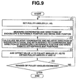
- FIG. 9 is a flowchart of processing procedures for creating a map
- FIG. 10 is an explanatory diagram showing how map data is created
- FIG. 11 is an explanatory diagram showing coordinates and the like of an endoscope's reference position and distal end when a map is created;
- FIG. 12B is a side view of the map expressed in the three-dimensional coordinate system at the distal end of the endoscope, as viewed from right to left in the direction of bending;
- FIG. 13 is a flowchart showing bending control procedures according to the present embodiment.
- FIG. 15 is an explanatory diagram showing how an Up direction of the distal end of the endoscope is made to coincide with a y-axis direction;
- FIG. 16 is an explanatory diagram showing how a quaternion is used
- FIG. 17 is an explanatory diagram showing how to calculate target pulley angles used to bend the distal end of the endoseope from a current setting to a target position;
- FIGS. 1 to 18 relate to a first embodiment of the present invention.
- FIG. 1 shows a configuration of an endoscope system according to the first embodiment of the present invention under exemplary conditions of use
- FIG. 2 shows an exemplary appearance of an endoscope apparatus
- FIG. 3 shows an internal configuration of an endoscope
- FIG. 4 shows an exemplary arrangement of coils on a distal side of an insertion portion
- FIG. 5 shows a detected insertion shape.
- FIG. 15 illustrates how an Up direction of the distal end of the endoscope is made to coincide with a y-axis direction
- FIG. 16 illustrates how a quaternion is used
- FIG. 17 illustrates how to calculate target pulley angles used to bend the distal end of the endoscope from a current setting to a target position
- FIG. 18 shows how a fold is held down by the distal end of the endoscope.
- the endoscope 2 has the elongated insertion portion 9 and inserted into a body cavity (lumen) of a patient 13 , i.e., a subject, lying on a bed 12 , and an operation portion 14 installed at a rear end of the insertion portion 9 .
- a connector at an end of a universal cable 15 extending from the operation portion 14 is connected to the light source device 3 which generates illuminating light as well as to the processor 4 serving as a signal processing unit which performs signal processing.
- the insertion portion 9 includes a distal end portion 10 installed at a distal end of the insertion portion 9 , a bending portion 18 configured to be bendable and installed at a rear end of the distal end portion 10 , and a flexible portion 19 configured to be flexible and extending from a rear end of the bending portion 18 to an operation portion 14 .
- the operation portion 14 contains, for example, a joystick 21 serving as bend command input means used to give a command to bend the bending portion 18 in a direction desired by an operator 20 .
- a joystick 21 serving as bend command input means used to give a command to bend the bending portion 18 in a direction desired by an operator 20 .
- the operator 20 can electrically bend the bending portion 18 via a motor unit 22 installed in the operation portion 14 and serving as electrical bending drive means.
- the PC proper 7 When the operator 20 selects an automatic bending control mode (described later), the PC proper 7 performs motor control for electrical bending control of the bending portion 18 via the motor unit 22 so that the distal side of the insertion portion 9 will turn to a running direction of a lumen through which the insertion portion 9 is passed.
- the endoscope apparatus 6 shown in FIG. 1 has an appearance such as shown in FIG. 2 .
- the PC proper 7 constitutes a component of the endoscope apparatus 6 as a control unit for the motor unit 22 in the endoscope 2 .
- the endoscope system In addition to a regular bending control mode in which the operator 20 inserts the endoscope 2 by manually operating the joystick 21 serving as bend command input means with the distal end portion 10 turned in the running direction of a lumens the endoscope system according to the present embodiment has an automatic bending control mode which involves estimating three-dimensionally a position of a dark part in a lumen (as a target position) from endoscopic images through image processing, estimating an insertion shape on the distal side of the insertion portion 9 , and thereby controlling electrically bending of the bending portion 18 so that the distal end of the insertion portion will turn to the target position.
- the term “distal end of the insertion portion” and the term “distal end of the endoscope” are used interchangeably herein.
- a light guide 31 which transmits illuminating light is passed through the insertion portion 9 .
- a rear end of the light guide 31 is connected to the light source device 3 via the operation portion 14 and universal cable 15 shown in FIG. 1 or FIG. 2 .
- Illuminating light from a lamp (not shown) in the light source device 3 is incident upon a rear end face of the light guide 31 . Then, the illuminating light transmitted by the light guide 31 is emitted forward from a light guide's front end face fixed to an illuminating window in the distal end portion 10 .
- a CCD output signal or image pickup signal photoelectrically converted by the CCD 33 is inputted in the processor 4 .
- the processor 4 performs signal processing of the image pickup signal, and thereby generates, for example, an RGB signal and the like as an endoscopic image signal (video signal) used to display an endoscopic image on the endoscope monitor 5 .
- the endoscopic image signal is inputted in the endoscope monitor 5 , and consequently the endoscopic image is displayed in an endoscopic image display area of the endoscope monitor 5 .
- the endoscopic image signal is also inputted in the PC proper 7 serving as an image processing/motor control apparatus which performs image processing and motor control (or bending control).
- the endoscopic image signal is used there for image processing to detect position information needed to insert the distal end of the insertion portion 9 along the running direction of the body cavity.
- insertion portion 9 of the endoscope 2 to detect insertion shape (also referred to as endoscope shape) of the insertion portion 9 , multiple UPD coils (hereinafter simply referred to as coils) 36 a, 36 b , 36 c , 36 d , . . . serving as position information generating means which generates respective position information are arranged, for example, at predetermined intervals from the distal end portion 10 to an appropriate position in the flexible portion 19 .
- the coils 36 a , 36 b , 36 c , 36 d , . . . are, for example, magnetic field generating coils which generate magnetic fields.
- By detecting coil positions of the coils 36 a, 36 b , 36 c , 36 d , . . . it is possible to calculate the insertion shape of the insertion portion 9 .
- the coil 36 c is placed in the bending portion 18 and the coil 36 d is placed at the rear end of the bending portion 18 .
- coil arrangement is not limited to the example shown in FIG. 3 .
- a map is generated to associate driving positions (specifically, rotational drive angles and pulley angles) of the bending drive means and three-dimensional positions of the distal end of the insertion portion 9 with each other by bending the bending portion 18 in all directions in which the bending portion 18 is bendable-up and down and left-and-right.
- FIG. 4 shows the distal side of the insertion portion 9 in enlarged form.
- the coils 36 a , 36 b , 36 c , 36 d , . . . are arranged on the distal side of the insertion portion 9 .
- a coil 36 a ′ orthogonal, for example, to the coil 36 a placed on the longitudinal axis is placed adjacent to the coil 36 a in the distal end portion 10 with a solenoid axis (axis of an winding) of the coil 36 a ′ turned into an upward bending direction (referred to as the Up bending direction or simply as the Up direction) when the bending portion 18 is bent.
- windings of the coil 36 a and coil 36 a ′ are orthogonal to each other.
- a cable on a rear side of the coils 36 a , 36 b , 36 c , 36 d , . . . is connected to the UPD apparatus 11 .
- the UPD apparatus 11 shown in FIG. 1 includes a UPD drive circuit (not shown) and sense coil unit 11 a , where the UPD drive circuit generates magnetic fields by applying a drive signal of a predetermined frequency to the coils 36 a , 36 b, 36 c , . . . and the sense coil unit 1 a is made up of multiple sense coils arranged in a predetermined positional relationship to detect magnetic fields.
- the UPD apparatus 11 includes a position detecting unit 11 b (see FIG. 2 ) which detects (calculates) positions of the coils 36 a , 36 b , 36 c , . . . based on detection signals from the multiple sense coils, an insertion shape calculation/display processing circuit 11 c which calculates the insertion shape of the insertion portion 9 (endoscope 2 ) based on position information about the coils 36 a , 36 b , 36 c , . . . and performs display processing of the calculated insertion shape, and a shape display monitor 11 d which displays the insertion shape.
- a position detecting unit 11 b see FIG. 2
- the UPD apparatus 11 includes a position detecting unit 11 b (see FIG. 2 ) which detects (calculates) positions of the coils 36 a , 36 b , 36 c , . . . based on detection signals from the multiple sense coils, an insertion shape calculation/display processing circuit
- An amount-of-twist detecting unit 23 which detects the amount of twist of the insertion portion 9 as shown in FIG. 1 is not strictly necessary if a specific bearing (e.g., the Up direction) of the distal end portion 10 can be detected by the coil 36 a ′ shown in FIG. 3 .
- the frame data of each frame serving as insertion state information includes creation time of the insertion shape data, display properties, supplementary information, three-dimensional coordinate data of the coil (coil coordinate data), and the like as shown in FIG. 6B .
- the coil coordinate data represents three-dimensional coordinates of the coils 36 a , 36 b , 36 c , 36 d , . . . arranged in sequence from distal side to proximal side (nearer to the operation portion 14 ) of the insertion portion 9 as shown in FIG. 6C .
- the endoscope 2 is of a direct view type, meaning that an observation direction (image pickup direction) via the image pickup apparatus 34 installed in the distal end portion 10 is parallel to the longitudinal axis of the insertion portion 9 . Also, the observation direction via the image pickup apparatus 34 coincides with the insertion direction.
- the pulleys 42 a and 42 b are coupled, respectively, to rotation axes of an UD motor 43 a for up and down bending (driving) and Rn motor 43 b for left and right bending (which may be referred to simply as motors 43 a and 43 b ) and rotated according to rotational directions of the motors 43 a and 43 b which can rotate in forward and reverse directions.
- the motors 43 a and 43 b serving as up-and-down and left-and-right bending drive means are controlled by the PC proper 7 connected with the motor unit 22 as shown in FIG. 7 .
- This configuration provides electrical bending drive means which rotates the pulleys 42 a and 42 b using the motors 43 a and 43 b to pull and relax (push-pull) the bending wires 41 u , 41 d , 41 l , and 41 r , and thereby electrically drives and bends the bending portion 18 .
- Rotation angles of the motors 43 a and 43 b (also referred to as motor angles) or the pulley angles are detected respectively, for example, by an up/down rotary encoder (UD encoder) 44 a and left/right rotary encoder (RL encoder 44 b ) mounted on the respective rotation axes of the motors 43 a and 43 b and serving as rotation angle detecting means or rotational position detecting means.
- Encoder outputs from the UD encoder 44 a and RL encoder 44 b are inputted in the PC proper 7 as shown in FIG. 7 .
- the motors 43 a and 43 b in the motor unit 22 controls electrically-driven bending using map information (described later) and based on the target position estimated by the UPD apparatus 11 and received from the PC proper 7 and the current position and direction of the distal end portion 10 (of the endoscope).
- the PC proper 7 has a function of bending control means.
- the PC proper 7 calculates the target position through image processing (described later) to determine the target direction of bending.
- the PC proper 7 controls amounts of rotational driving of the motors 43 a and 43 b (which correspond to the pulley angles of the pulleys 42 a and 42 b ) so as to bring the encoder outputs into coincidence with the amount of operation of the joystick 21 and thereby bends the bending portion 18 by the specified amount of bending.
- the joystick 21 is equipped, for example, with an encoder or potentiometer (not shown) to detect amounts of tilting operations in an up-and-down direction and left-and-right direction.
- the encoder or potentiometer finds specified amount of bending and information about a specified direction.
- the PC proper 7 performs bending control so as to simply bring the encoder outputs into coincidence with the specified amount of bending.
- FIG. 7 shows a functional configuration of the PC proper 7 .
- An endoscopic image signal from the processor 4 is stored as endoscopic image data in a memory 52 via an A/D converter circuit 51 in the PC proper 7 .
- Information about coil coordinates and directions supplied from the UPD apparatus 11 is stored in the memory 52 via a coil information acquisition thread 53 as endoscope shape parameters, specifically, as data on coil coordinate positions, coil directions, and the distal end's Up direction.
- the endoscopic image data and endoscope shape parameter data are outputted to a main processing unit (or main thread) 55 formed by a CPU.
- the CPU may be configured to perform not only processes of the main processing unit 55 , but also other processes such as processes of an amount-of-bending control thread 56 described later.
- the main processing unit 55 in FIG. 7 may be configured to perform the processes of the amount-of-bending control thread 56 .
- the encoder outputs from the motor unit 22 of the endoscope 2 are inputted in the amount-of-bending control thread 56 which also accepts input of amount-of-bending parameter data generated by the main processing unit 55 and stored temporarily in the memory 52 .
- the amount-of-bending parameters include additional pulley angles by which the pulley needs to be moved from the current pulley angles in a direction of the target position.
- the additional pulley angles are relative pulley angles given, for example, in the form of differential values (described later).
- the relative amount of twist detected by the amount-of-twist detecting unit 23 is stored, for example, as one of the endoscope shape parameters in the memory 52 via an amount-of-twist acquisition thread 57 .
- the memory 52 also stores information of a data map (lookup table) 58 obtained by measuring and digitizing a relationship between pulley angle positions and three-dimensional positions and directions of the endoscope's distal end, where the pulley angle positions which are handled by the bending drive means correspond to the amount of bending (including bending directions) produced when the bending portion 18 is bent up and down or left and right.
- a data map lookup table
- the memory 52 serves as map information storage means.
- Motor angles which are rotation angles of the motors 43 a and 43 b may be used instead of the pulley angles.
- gear angles which are rotation angles of gears may be used if the pulleys 42 a and 42 b are rotationally driven via gears coupled to the rotation axes of the motors 43 a and 43 b.
- a reference (coordinate) position is established at such a position of the insertion portion 9 that is located near the distal end of the insertion portion 9 and hardly affected when the bending portion 18 is bent. Specifically, the reference position is established at the rear end of the bending portion 18 .
- map information data of the map 58 (the data is also referred to as map information) can be used commonly in any bent condition (condition of the pulley angles), provided that the same endoscope 2 is used.
- the map information accommodates cases in which a bendable range of the bending portion 18 (i.e., maximum pulley angle) varies among different directions, such as between up-and-down direction and left-and-right direction or between up and down directions. Also, the map information accommodates bending not only in four directions of up, down, left, and right, but also in any intermediate direction, such as direction between up and left directions.
- a bendable range of the bending portion 18 i.e., maximum pulley angle
- data of the map information is generated using a predetermined bending direction as a reference direction.
- the map information is generated with bending in the up direction (U or Up) represented by a y axis on the map 58 (described later).
- the coordinate system and target direction of the endoscope's distal end are matched to the coordinate system of the map information.
- the main processing unit 55 calculates the pulley angles to bend the bending portion 18 in the direction of the target position and sends the calculated pulley angles to the amount-of-bending control thread 56 via the memory 52 .
- the amount-of-bending control thread 56 converts the calculated pulley angles into motor voltages (more specifically, a UD motor voltage value and RL motor voltage value) and outputs the motor voltages to the UD motor 43 a and RL motor 43 b in the motor unit 22 .
- FIG. 8 shows a functional configuration of the main processing unit 55 .
- the main processing unit 55 has functions of an intra-image target position detecting section 55 a which detects the target position based on lumen information in an endoscopic image, an endoscope shape processing section 55 b which detects the positions and directions of various parts of the endoscope using coil coordinates, and an amount-of-twist calculating section 55 c which calculates an absolute amount of twist from a relative amount of twist.
- the endoscope shape processing section 55 b has a function of position and direction detecting means which detects the position and direction of the endoscope's distal end.
- the amount-of-twist calculating section 55 c performs its process when a relative amount of twist is inputted.
- the intra-image target position detecting section 55 a detects a center position (or center of gravity position) of a dark part which corresponds to the running direction of the lumen in an endoscopic image, where the center position of the dark part is detected in the endoscopic image as two-dimensional position information.
- the position of the dark part is detected by taking into consideration pixel size, focal length, and other values of the CCD 33 . Then, based on information about the position of the dark part in relation to the current distal end position of the insertion portion 9 , the direction of the position of the dark part is detected as the insertion direction of the insertion portion's distal end (endoscope's distal end).
- a three-dimensional position including a value in a depth dimension of the dark part is calculated, for example, by SFS-based image processing, where SFS stands for Shape From Shading which is a technique for shape recovery from shading.
- SFS stands for Shape From Shading which is a technique for shape recovery from shading.
- the three-dimensional position information is used as a target position to which the distal end of the insertion portion should be introduced (oriented).
- the target position detected by the intra-image target position detecting section 55 a is transformed into a target position in the world coordinate system by a coordinate system transformation unit of the intra-image target position detecting section 55 a .
- the direction of the resulting target position corresponds to the target direction in which the distal end of the insertion portion should be inserted.
- the resulting target position is outputted to an amount-of-bending calculating section (pulley angle calculating portion) 55 d which calculates the amount of bending or pulley angles.
- the absolute amount of twist is inputted in the amount-of-bending calculating section 55 d from the amount-of-twist calculating section 55 c
- the absolute amount of twist is not calculated if the amount-of-twist detecting unit 23 is not installed.
- the rotation angle by which the insertion portion 9 is rotated around its axis is detected based on the amount of twist detected by the amount-of-twist detecting unit 23 .
- the bending direction of the endoscope's distal end can be calculated by detecting the positions of the coils 36 a and 36 a ′ shown in FIG. 4 (without using the amount of twist because the Up direction can be detected).
- the amount-of-bending calculating section 55 d calculates the current bent condition of the endoscope's distal end from information about the position and direction of the endoscope's distal end out of inputted information with reference to the map information.
- the amount-of-bending calculating section 55 d calculates the pulley angles used to bend the distal end of the endoscope from the current bent condition toward the target position, with reference to the map information.
- the amount-of-bending calculating section 55 d serves as calculating means for calculating the current position and direction of the endoscope's distal end and calculating means for calculating the direction of the target position.
- the calculated pulley angles are outputted as additional pulley angles to the amount-of-bending control thread 56 via the memory 52 .
- the amount-of-bending control thread 56 converts the additional pulley angles into motor voltages (UD motor voltage value and RL motor voltage) and applies the motor voltages to the UD motor 43 a and RL motor 43 b in the motor unit 22 .
- the bending portion 18 is bent so as to bring the distal end of the endoscope into coincidence with the direction of the target position.
- the map 58 is created before the endoscope is shipped, for example, from the factory.
- Step S 1 a map creator sets the pulley angles ( ⁇ 1 , ⁇ 2 ) in the up-and-down and left-and-right directions using the pulley angle ⁇ 1 in the up-and-down direction and pulley angle ⁇ 2 in the left-and-right direction.
- FIG. 10 to carry out Step S 1 concretely, representative pulley angle values are specified as positions on the map.
- FIG. 10 shows an example of the map used in Step S 1 .
- the map is made, for example, of a tetragonal lattice (grid).
- the map 58 is completed.
- the pulley angle ⁇ 1 in the up-and-down direction (denoted by Up and D) and pulley angle ⁇ 2 in the left-and-right direction (denoted by L and R) can be specified within a range of bending characteristics of the endoscope 2 used actually.
- actually available pulley angle ranges are from ⁇ Dm to ⁇ Um for the pulley angle ⁇ 1 in the up-and-down direction, and from ⁇ Lm to ⁇ Rm for the pulley angle ⁇ 2 in the left-and-right direction.
- ⁇ Dm and ⁇ Lm are defined as negative values.
- the upward direction (Up direction) is represented by the y axis as a reference direction of the map 58 , as shown in FIG. 10 .
- Step S 1 ( ⁇ 1 i , ⁇ 2 j ), for example, are actually set as the pulley angles ( ⁇ 1 , ⁇ 2 ), where i and j represent the pulley angles on the grid.
- a display example is shown in FIG. 10 .
- a grid offset value ⁇ of the pulley angle values is used in the flowchart (Step S 4 ).
- the map creator By maintaining the pulley angles ( ⁇ 1 i , ⁇ 2 j ) set in Step S 1 , the map creator measures coordinates and directions of the endoscope's reference position and distal end position in Step S 2 .
- FIG. 11 shows an example of the endoscope's reference position coordinates (X 0 , Y 0 , Z 0 ), endoscope's distal end position coordinates (Xij, Yij, Zij), and directions D 0 and Dij at the given positions, measured in Step S 2 with the pulley angles ( ⁇ 1 i, ⁇ 2 j ) maintained.
- the direction D 0 contains information about the axial direction at the endoscope's reference position with reference to a specific direction of bending (specifically, the up direction of bending).
- the relative coordinates (Xii ⁇ X 0 , Yij ⁇ Y 0 , Zij ⁇ Z 0 ) and relative direction (Dij ⁇ D 0 ) of the endoscope's distal end position are written to the position (map position or map data position) at a grid point for the pulley angles ( ⁇ 1 i , ⁇ 2 j ) in FIG. 10 , by being associated with each other.
- the values of the position coordinates and direction of the endoscopers distal end are written to each map data position by being associated with each set of pulley angles ( ⁇ 1 i , ⁇ 2 j ).
- the values of the relative position coordinates and relative direction with respect to the endoscope's reference position are associated with the pulley angles.
- Step S 4 the map creator adds the offset value ⁇ to the pulley angles ⁇ 1 and ⁇ 2 to obtain pulley angles ⁇ 1 and ⁇ 2 at an adjacent grid position.
- Step S 5 the map creator determines whether the pulley angles ⁇ 1 and ⁇ 2 have exceeded the ranges of the pulley angles for the endoscope. If the ranges are not exceeded, the map creator returns to Step S 1 and repeats processes of Steps S 1 to S 5 . Actually, the processes of Steps S 1 to S 5 are repeated within the ranges of the pulley angles in the up-and-down direction and left-and-right direction as long as the bending portion 18 can be bent.
- the map 58 When each data item in the map 58 is expressed in a three-dimensional coordinate system representing the endoscope's distal end, the map 58 presents a curved surface which represents a locus obtained by plotting the endoscope's distal end position in the three-dimensional coordinate system in the case where a bending portion 18 is bent.
- the axial direction of the distal end at the endoscope's distal end position is digitized as direction information together with the position.
- the procedures for creating the map 58 in FIG. 9 may be automated.
- FIGS. 12A and 12B a line segment which represents the direction of the endoscope's distal end is shown three-dimensionally. Part of the map 58 viewed from a direction different from the directions in FIGS. 12A and 12B is schematically shown by way of example in FIG. 17 .
- FIG. 17 a line segment which represents the direction of the endoscope's distal end in FIGS. 12A and 122B is shown vectorially by attaching an arrow to an end of the line segment.
- the map 58 is created before shipment from the factory, this is not restrictive, and a program for creating a map 58 may be stored in the PC proper 7 so that the PC proper 7 will create a map 58 according to the program. Alternatively, a program for creating a map 58 may be transferred to the endoscope system 1 which does not have a map 58 , allowing the endoscope system 1 to create a map 58 . In this way, the endoscope system I may be provided with means of creating a map 58 .
- Step S 11 initialization is performed in Step S 11 .
- Step S 12 the main processing unit 55 acquires coil information about the coils 36 a , 36 b , 36 c . . . arranged in the insertion portion 9 , i.e., information about coil positions.
- Step S 13 the CPU functioning as the main processing unit 55 calculates the position and direction of the endoscope's distal end based on the information about coil positions.
- Step S 14 the CPU acquires image data of an endoscopic image.
- Step S 15 the CPU corrects distortion in image data. Specifically, the CPU corrects distortion in image data obtained by the objective lens 32 , which is prone to distortion aberrations.
- Step S 16 using the endoscopic image, the CPU detects a target position to pass through the distal end of the endoscope. Specifically, the CPU detects the position of a luminal dark part.
- Step S 17 the CPU transforms the target position detected in Step S 16 , which is two-dimensional position information, into three-dimensional coordinates using the SFS technique or the like.
- Step S 18 using the map information, the CPU calculates target pulley angles (described later with reference to FIG. 14 ) which correspond to the bending direction to bring the direction of the endoscope's distal end into coincidence with the direction of the target position (or orient the distal end in the direction of the target position).
- Step S 19 the CPU calculates motor voltages corresponding to the calculated target pulley angles.
- the calculation is performed as a process of the amount-of-bending control thread 56 in the exemplary configuration shown in FIG. 7 .
- the calculated motor voltages are applied to the motors 43 a and 43 b in the motor unit 22 to electrically drive and bend the bending portion 18 through rotation of the motors 43 a and 43 b.
- Step S 21 the CPU functioning as the main processing unit 55 transforms the coordinates of the target position into relative coordinates defined with respect to the endoscope's reference position.
- Step S 22 the CPU performs a transformation such that the Up direction on the distal side of the endoscope will coincide with the y axis and that the axial direction of a coil position B will coincide with the Z axis.
- FIG. 15 illustrates the process of Step S 22 .
- Step S 21 the distal side of the endoscope is generally in a state shown in FIG. 15 .
- the coil position B coincides with a reference position at the rear end of the bending portion as shown in FIG. 15 .
- a position A of the endoseope's distal end (represented concretely by a coil at the distal end) is located on the map 58 (the curved surface of the map), and generally the Up direction of the endoscope in this state does not coincide with the Up direction of the map 58 .
- a rotational transform is performed such that the Up direction of the endoscope will coincide with a reference direction (for example, the y axis) predefined as the Up direction of the map 58 .
- a reference direction for example, the y axis
- the target position also moves as indicated by an arrow in FIG. 15 .
- the rotation can be performed easily using a quaternion.
- a C axis orthogonal to the Up direction of the endoscope's distal end and the y axis of the map 58 in FIG. 15 is defined as shown in FIG. 16 . Then, the Up direction of the endoscope's distal end and the y-axis direction of the map 58 are brought into coincidence with each other by rotating them around the C axis by a rotation angle ⁇ .
- the rotation by the rotation angle ⁇ moves the coil position A at the distal end to a position denoted by reference numeral B′.
- a quaternion generated using a direction vector, which defines the C axis, and the rotation angle ⁇ makes it easy to transform the coil position A at the distal end.
- a similar transformation is performed so as to bring the axial direction of the resulting coil position B′ into coincidence with the Z axis.
- Step S 22 in FIG. 14 the CPU calculates position coordinates (e.g., consecutive coordinates) on the map coordinate system corresponding to the direction of the target position in Step S 23 .
- Step S 23 belongs to the direction-of-the-target-position calculating unit.
- the CPU After calculating a map position which approximates the direction of the target position in Steps S 21 to S 23 , the CPU similarly processes the current distal end of the endoscope in Steps S 24 to S 26 to calculate the corresponding position on the map.
- Step S 24 the CPU transforms the coordinates of the endoscope's distal end into relative coordinates defined with respect to the endoscope's reference position.
- Step S 25 the CPU performs a transformation such that the Up direction of the endoscope will coincide with the y axis and that the axial direction of the coil position B will coincide with the Z axis.
- Step S 26 the CPU calculates position coordinates (e.g., consecutive coordinates) on the map coordinate system corresponding to the position of the endoscope's distal end. Step S 26 makes it possible to calculate the direction in which the current position of the endoscope's distal end should be oriented. Step S 26 belongs to the direction-of-the-distal-end calculating unit.
- Step S 27 the CPU calculates values of the target pulley angles based on the map coordinates.
- FIG. 17 shows how the target pulley angles are calculated in Step S 27 .
- corresponding pulley angles are calculated as current absolute pulley angle values.
- Step S 23 target position pulley angles ( ⁇ c, ⁇ d) corresponding to the target position are calculated as absolute pulley angle values.
- Differential values between the absolute pulley angle values i.e., relative pulley angles ( ⁇ c ⁇ a, ⁇ d ⁇ b), are calculated as target pulley angles.
- the target pulley angles are set as a bending control target (shown in Step S 18 in FIG. 13 ) and used for bending control in moving the distal end of the endoscope from the current position to the target position.
- Step S 27 to bend the distal end of the endoscope from the current state (generally a bent state) toward the target position, the amount of bending (driving) is determined from the differential values (i.e., relative values) between the pulley angles ( ⁇ a, ⁇ b) corresponding to the current bent condition and the pulley angles ( ⁇ c, ⁇ d) corresponding to the target position.
- the differential values i.e., relative values
- the pulley angle values corresponding to the current position and direction of the endoscope's distal end on the map 58 are used instead of the actual pulley angle values on the hand side.
- three-dimensional bending information about the bending portion 18 has been gathered by bending the bending portion 18 and digitized as the map 58 .
- the present embodiment makes it possible to perform bending control using simpler arithmetic operations.
- the present embodiment enables highly responsive bending control.
- the (data) map 58 is generated by digitizing the coordinate values of a large number of pulley angles produced by bending the bending portion 18 finely in the up, down, left, and right directions and three-dimensional position and direction of the endoscope's distal end corresponding to the coordinate values of each pulley angle.
- desired values can be calculated easily from available values close to the desired values using, for example, the Pseudo-Newton method which is an approximation method (approximate estimation method).
- the position and pulley angle values at each grid point are known, amounts of deviation from the direction of the target position are determined at multiple grid points.
- values of a direction which reduces the three-dimensional amounts of deviation to sufficiently small values are calculated as approximate values using the Pseudo-Newton method, making it possible to calculate the target position's pulley angles ( ⁇ c, ⁇ d) corresponding to the calculated direction.
- the present embodiment enables accurate bending control.
- the present embodiment makes it easy to carry out a maneuver such as holding down a fold of the intestinal tract by the distal end of the endoscope.
- the present embodiment makes it easy to carry out a maneuver such as holding down a fold 60 in the direction indicated by an arrow using the distal end of the endoscope (represented schematically by the coil at the distal end) as shown in FIG. 18 .
- target pulley angles and the like can be calculated using data on the grid (at data points of the map) almost without using interpolation or the like.
- the differential values between the pulley angle values at the current position of the endoscope's distal end and the pulley angle values at the position corresponding to the target position can be calculated as target pulley angles.
- pulley angles on the map 58 may be calculated based on position information about the target position instead of using direction information about the target position.
- FIG. 19 shows the endoscope 2 and PC proper 7 according a variation.
- the endoscope 2 may incorporate a map information storage unit 61 (of a non-volatile memory or the like) containing information of the map 58 described above.
- a CPU 62 functioning as the main processing unit 55 and the like of the PC proper 7 may read information out of the map 58 and store the information on a hard disk 63 , the non-volatile memory, or the memory 52 of the PC proper 7 in order to use the information in bending control.
- the information of the map 58 may be stored on the. PC proper 7 by being associated with ID information possessed by the endoscope 2 .
- the endoscope 2 includes an ID information generating unit (abbreviated to ID in FIG. 19 ) 64 which generates ID information unique to the endoscope 2 .
- ID information generating unit abbreviated to ID in FIG. 19
- the information of the map 58 for the endoscope may be stored on the PC proper 7 together with the ID information on the endoscope 2 .
- ID information IDa is stored in pairs with map information MDa while ID information IDb is stored in pairs with map information MDb.
- the CPU 62 can read the ID information on the endoscope 2 and use the information of the map 58 corresponding to the ID information in bending control.
- the present variation enables accurate bending control.
- the present variation provides the same advantages as those of the first embodiment.
Abstract
Description
Claims (20)
Applications Claiming Priority (2)
| Application Number | Priority Date | Filing Date | Title |
|---|---|---|---|
| JP2007-318658 | 2007-12-10 | ||
| JP2007318658A JP5295555B2 (en) | 2007-12-10 | 2007-12-10 | Endoscope system |
Publications (2)
| Publication Number | Publication Date |
|---|---|
| US20090149711A1 US20090149711A1 (en) | 2009-06-11 |
| US8308635B2 true US8308635B2 (en) | 2012-11-13 |
Family
ID=40385501
Family Applications (1)
| Application Number | Title | Priority Date | Filing Date |
|---|---|---|---|
| US12/330,994 Active 2031-09-13 US8308635B2 (en) | 2007-12-10 | 2008-12-09 | Endoscope system |
Country Status (4)
| Country | Link |
|---|---|
| US (1) | US8308635B2 (en) |
| EP (1) | EP2070465B1 (en) |
| JP (1) | JP5295555B2 (en) |
| CN (1) | CN101455554B (en) |
Cited By (4)
| Publication number | Priority date | Publication date | Assignee | Title |
|---|---|---|---|---|
| US20100249506A1 (en) * | 2009-03-26 | 2010-09-30 | Intuitive Surgical, Inc. | Method and system for assisting an operator in endoscopic navigation |
| EP3017759A1 (en) * | 2013-07-02 | 2016-05-11 | Olympus Corporation | Medical instrument |
| US20160192823A1 (en) * | 2014-08-11 | 2016-07-07 | Olympus Corporation | Endoscope system |
| US10856770B2 (en) | 2009-03-26 | 2020-12-08 | Intuitive Surgical Operations, Inc. | Method and system for providing visual guidance to an operator for steering a tip of an endoscopic device towards one or more landmarks in a patient |
Families Citing this family (31)
| Publication number | Priority date | Publication date | Assignee | Title |
|---|---|---|---|---|
| WO2011040111A1 (en) * | 2009-09-30 | 2011-04-07 | オリンパスメディカルシステムズ株式会社 | Endoscope device |
| JP4804594B2 (en) * | 2009-09-30 | 2011-11-02 | オリンパスメディカルシステムズ株式会社 | Endoscope apparatus and bending drive control method |
| ES2374904B1 (en) * | 2010-07-16 | 2013-01-30 | Juan Carlos Rivera García | AUTOMATIC GUIDE DEVICE OF THE DISTAL END OF A FIBROBRONCOSCOPE / VIDEOBRONCOSCOPE. |
| WO2012014532A1 (en) * | 2010-07-28 | 2012-02-02 | オリンパスメディカルシステムズ株式会社 | Endoscope, and method for inserting and bending the endoscope |
| JP5766940B2 (en) * | 2010-12-01 | 2015-08-19 | オリンパス株式会社 | Tubular insertion system |
| EP2649922A4 (en) * | 2011-02-28 | 2018-01-17 | Olympus Corporation | Endoscope and medical apparatus |
| CN103068297B (en) * | 2011-03-30 | 2015-12-02 | 奥林巴斯株式会社 | Endoscopic system |
| US8900131B2 (en) * | 2011-05-13 | 2014-12-02 | Intuitive Surgical Operations, Inc. | Medical system providing dynamic registration of a model of an anatomical structure for image-guided surgery |
| EP2617347B1 (en) * | 2011-07-28 | 2014-12-31 | Olympus Medical Systems Corp. | Endoscope |
| JP5548315B2 (en) * | 2012-05-23 | 2014-07-16 | オリンパスメディカルシステムズ株式会社 | Electronic endoscope system |
| JP6132585B2 (en) * | 2013-02-21 | 2017-05-24 | オリンパス株式会社 | Subject insertion system |
| KR102087595B1 (en) * | 2013-02-28 | 2020-03-12 | 삼성전자주식회사 | Endoscope system and control method thereof |
| JP5802866B2 (en) * | 2013-06-18 | 2015-11-04 | オリンパス株式会社 | Insertion device |
| CN103345055B (en) * | 2013-06-18 | 2015-03-04 | 深圳市亚泰光电技术有限公司 | Power input mechanism of endoscope and endoscope |
| JP6116426B2 (en) | 2013-07-25 | 2017-04-19 | オリンパス株式会社 | Manipulator system |
| JP6027947B2 (en) * | 2013-07-26 | 2016-11-16 | オリンパス株式会社 | Manipulator system |
| CN103479320B (en) * | 2013-09-25 | 2015-08-26 | 深圳先进技术研究院 | Active snakelike endoscope robot system |
| DK177984B9 (en) * | 2013-11-12 | 2015-03-02 | Simonsen & Weel As | Device for endoscopy |
| JP2015154814A (en) * | 2014-02-20 | 2015-08-27 | オリンパス株式会社 | Manipulator system and control method of the same |
| JP2015181643A (en) * | 2014-03-24 | 2015-10-22 | オリンパス株式会社 | Curved shape estimation system, tubular insert system, and method for estimating curved shape of curved member |
| DE112014007268B4 (en) * | 2014-12-19 | 2019-02-07 | Olympus Corporation | Insertion / removal support apparatus and insertion / removal support method |
| DE112014007273T5 (en) * | 2014-12-19 | 2017-11-02 | Olympus Corporation | Insertion / removal support apparatus and insertion / removal support method |
| US11096552B2 (en) | 2015-06-30 | 2021-08-24 | Canon U.S.A., Inc. | Method and apparatus for controlling manipulator |
| JP6543128B2 (en) * | 2015-07-29 | 2019-07-10 | オリンパス株式会社 | Endoscope device |
| WO2017217162A1 (en) * | 2016-06-16 | 2017-12-21 | 富士フイルム株式会社 | Navigation device, navigation method, and endoscope system |
| US20180117731A1 (en) * | 2016-09-09 | 2018-05-03 | Advanced Turbine Support, LLC | Industrial High Speed Micro Drill |
| JP7049220B2 (en) * | 2018-08-30 | 2022-04-06 | オリンパス株式会社 | How to operate the image acquisition device and the image acquisition device |
| CN110720882A (en) * | 2019-10-16 | 2020-01-24 | 深圳开立生物医疗科技股份有限公司 | Endoscope system and endoscope operation control method |
| JP2023113300A (en) * | 2022-02-03 | 2023-08-16 | キヤノン株式会社 | Continuous body robot control system and continuous body robot control method |
| WO2023225209A1 (en) * | 2022-05-20 | 2023-11-23 | Boston Scientific Scimed, Inc. | Trajectory tracking for medical device |
| CN117100197B (en) * | 2023-10-23 | 2024-02-20 | 杭州堃博生物科技有限公司 | Sheath bending adjustment method and device, nonvolatile storage medium and electronic equipment |
Citations (16)
| Publication number | Priority date | Publication date | Assignee | Title |
|---|---|---|---|---|
| JPH07346A (en) | 1993-06-15 | 1995-01-06 | Olympus Optical Co Ltd | Endoscope system |
| US5658238A (en) | 1992-02-25 | 1997-08-19 | Olympus Optical Co., Ltd. | Endoscope apparatus capable of being switched to a mode in which a curvature operating lever is returned and to a mode in which the curvature operating lever is not returned |
| US6295368B1 (en) * | 1998-04-10 | 2001-09-25 | Olympus Optical Co., Ltd. | Endoscopic image processing system capable of estimating absolute shape of object entity |
| JP2006192056A (en) | 2005-01-13 | 2006-07-27 | Olympus Corp | Motor-driven curving type endoscope |
| WO2007023631A1 (en) | 2005-08-25 | 2007-03-01 | Olympus Medical Systems Corp. | Device for analyzing endoscope insertion shape and system for analyzing endoscope insertion shape |
| JP2007054307A (en) | 2005-08-24 | 2007-03-08 | Olympus Corp | Controller for bent part of endoscopic system |
| US20070112255A1 (en) * | 2002-02-07 | 2007-05-17 | Olympus Optical Co., Ltd. | Electric bending endoscope |
| EP1800593A1 (en) | 2004-09-27 | 2007-06-27 | Olympus Corporation | Curve control device |
| US20070149852A1 (en) * | 2004-09-07 | 2007-06-28 | Toshiaki Noguchi | Endoscope |
| EP1818005A1 (en) | 2004-12-03 | 2007-08-15 | Olympus Corporation | Power driven bending endoscope with detachable insertion portion |
| CN101026988A (en) | 2004-09-27 | 2007-08-29 | 奥林巴斯株式会社 | Bending control device |
| EP1884185A1 (en) | 2005-05-24 | 2008-02-06 | Olympus Medical Systems Corp. | Endoscope |
| US20080045794A1 (en) * | 2000-04-03 | 2008-02-21 | Amir Belson | Steerable segmented endoscope and method of insertion |
| US20090299136A1 (en) * | 2007-02-14 | 2009-12-03 | Olympus Medical Systems Corp. | Endoscopic system for surgical instrument position control and position control method thereof |
| US20100298641A1 (en) * | 2009-01-15 | 2010-11-25 | Olympus Medical Systems Corp. | Endoscope system |
| US20110237889A1 (en) * | 2009-09-30 | 2011-09-29 | Olympus Medical Systems Corp. | Endoscope apparatus |
Family Cites Families (2)
| Publication number | Priority date | Publication date | Assignee | Title |
|---|---|---|---|---|
| JP3973504B2 (en) * | 2002-07-15 | 2007-09-12 | 株式会社日立製作所 | Tow positioning device |
| JP4794992B2 (en) * | 2005-11-16 | 2011-10-19 | オリンパスメディカルシステムズ株式会社 | Insertion monitoring device |
-
2007
- 2007-12-10 JP JP2007318658A patent/JP5295555B2/en active Active
-
2008
- 2008-12-04 EP EP08021071A patent/EP2070465B1/en not_active Expired - Fee Related
- 2008-12-09 US US12/330,994 patent/US8308635B2/en active Active
- 2008-12-10 CN CN2008101793734A patent/CN101455554B/en active Active
Patent Citations (18)
| Publication number | Priority date | Publication date | Assignee | Title |
|---|---|---|---|---|
| US5658238A (en) | 1992-02-25 | 1997-08-19 | Olympus Optical Co., Ltd. | Endoscope apparatus capable of being switched to a mode in which a curvature operating lever is returned and to a mode in which the curvature operating lever is not returned |
| JPH07346A (en) | 1993-06-15 | 1995-01-06 | Olympus Optical Co Ltd | Endoscope system |
| US6295368B1 (en) * | 1998-04-10 | 2001-09-25 | Olympus Optical Co., Ltd. | Endoscopic image processing system capable of estimating absolute shape of object entity |
| US20080045794A1 (en) * | 2000-04-03 | 2008-02-21 | Amir Belson | Steerable segmented endoscope and method of insertion |
| US20070112255A1 (en) * | 2002-02-07 | 2007-05-17 | Olympus Optical Co., Ltd. | Electric bending endoscope |
| US20070149852A1 (en) * | 2004-09-07 | 2007-06-28 | Toshiaki Noguchi | Endoscope |
| CN101026988A (en) | 2004-09-27 | 2007-08-29 | 奥林巴斯株式会社 | Bending control device |
| EP1800593A1 (en) | 2004-09-27 | 2007-06-27 | Olympus Corporation | Curve control device |
| US20070173694A1 (en) * | 2004-09-27 | 2007-07-26 | Olympus Corporation | Bending control device |
| EP1818005A1 (en) | 2004-12-03 | 2007-08-15 | Olympus Corporation | Power driven bending endoscope with detachable insertion portion |
| JP2006192056A (en) | 2005-01-13 | 2006-07-27 | Olympus Corp | Motor-driven curving type endoscope |
| EP1884185A1 (en) | 2005-05-24 | 2008-02-06 | Olympus Medical Systems Corp. | Endoscope |
| US20090048488A1 (en) * | 2005-05-24 | 2009-02-19 | Olympus Medical Systems Corp. | Endoscope |
| JP2007054307A (en) | 2005-08-24 | 2007-03-08 | Olympus Corp | Controller for bent part of endoscopic system |
| WO2007023631A1 (en) | 2005-08-25 | 2007-03-01 | Olympus Medical Systems Corp. | Device for analyzing endoscope insertion shape and system for analyzing endoscope insertion shape |
| US20090299136A1 (en) * | 2007-02-14 | 2009-12-03 | Olympus Medical Systems Corp. | Endoscopic system for surgical instrument position control and position control method thereof |
| US20100298641A1 (en) * | 2009-01-15 | 2010-11-25 | Olympus Medical Systems Corp. | Endoscope system |
| US20110237889A1 (en) * | 2009-09-30 | 2011-09-29 | Olympus Medical Systems Corp. | Endoscope apparatus |
Cited By (9)
| Publication number | Priority date | Publication date | Assignee | Title |
|---|---|---|---|---|
| US20100249506A1 (en) * | 2009-03-26 | 2010-09-30 | Intuitive Surgical, Inc. | Method and system for assisting an operator in endoscopic navigation |
| US10004387B2 (en) * | 2009-03-26 | 2018-06-26 | Intuitive Surgical Operations, Inc. | Method and system for assisting an operator in endoscopic navigation |
| US10524641B2 (en) | 2009-03-26 | 2020-01-07 | Intuitive Surgical Operations, Inc. | Method and system for assisting an operator in endoscopic navigation |
| US10856770B2 (en) | 2009-03-26 | 2020-12-08 | Intuitive Surgical Operations, Inc. | Method and system for providing visual guidance to an operator for steering a tip of an endoscopic device towards one or more landmarks in a patient |
| US11744445B2 (en) | 2009-03-26 | 2023-09-05 | Intuitive Surgical Operations, Inc. | Method and system for assisting an operator in endoscopic navigation |
| EP3017759A1 (en) * | 2013-07-02 | 2016-05-11 | Olympus Corporation | Medical instrument |
| EP3017759A4 (en) * | 2013-07-02 | 2017-05-10 | Olympus Corporation | Medical instrument |
| US10433762B2 (en) | 2013-07-02 | 2019-10-08 | Olympus Corporation | Medical instrument |
| US20160192823A1 (en) * | 2014-08-11 | 2016-07-07 | Olympus Corporation | Endoscope system |
Also Published As
| Publication number | Publication date |
|---|---|
| CN101455554A (en) | 2009-06-17 |
| JP2009136618A (en) | 2009-06-25 |
| EP2070465B1 (en) | 2011-08-03 |
| JP5295555B2 (en) | 2013-09-18 |
| CN101455554B (en) | 2013-07-31 |
| US20090149711A1 (en) | 2009-06-11 |
| EP2070465A1 (en) | 2009-06-17 |
Similar Documents
| Publication | Publication Date | Title |
|---|---|---|
| US8308635B2 (en) | Endoscope system | |
| US8454497B2 (en) | Endoscope apparatus and bending drive control method | |
| US8597178B2 (en) | Active drive type medical apparatus and drive control method | |
| US8708892B2 (en) | Endoscope with controlled bending sections | |
| EP2130479B1 (en) | Device for controlling position of treatment instrument for endoscope | |
| JP5153787B2 (en) | Endoscope bending control device and endoscope system | |
| EP1800593B1 (en) | Curve control device | |
| US8308633B2 (en) | Manipulator operation system | |
| JP4551051B2 (en) | Ultrasonic diagnostic equipment | |
| US10932875B2 (en) | Manipulator, medical system, and medical system control method | |
| JP5932172B2 (en) | Endoscope system | |
| JP5137540B2 (en) | Endoscope system | |
| WO2011040111A1 (en) | Endoscope device | |
| JP2007319622A (en) | Endoscope system | |
| JP7385731B2 (en) | Endoscope system, image processing device operating method, and endoscope | |
| WO2014123066A1 (en) | Electrically powered endoscope | |
| JP5841366B2 (en) | Medical equipment | |
| CN117297773A (en) | Surgical instrument control method, surgical robot, and storage medium | |
| JP2969531B2 (en) | Endoscope device | |
| JP4624575B2 (en) | Endoscope system | |
| WO2022219878A1 (en) | Medical observation system, medical image processing method, and information processing device | |
| WO2023149232A1 (en) | Continuum robot control system and continuum robot control method | |
| JP6906342B2 (en) | Endoscope system | |
| JP2008253787A (en) | Ultrasonic diagnostic apparatus |
Legal Events
| Date | Code | Title | Description |
|---|---|---|---|
| AS | Assignment |
Owner name: OLYMPUS MEDICAL SYSTEMS CORP., JAPAN Free format text: ASSIGNMENT OF ASSIGNORS INTEREST;ASSIGNORS:TANAKA, HIDEKI;HASEGAWA, JUN;NAKAMURA, TOSHIO;REEL/FRAME:021948/0975 Effective date: 20081112 |
|
| STCF | Information on status: patent grant |
Free format text: PATENTED CASE |
|
| FEPP | Fee payment procedure |
Free format text: PAYOR NUMBER ASSIGNED (ORIGINAL EVENT CODE: ASPN); ENTITY STATUS OF PATENT OWNER: LARGE ENTITY |
|
| AS | Assignment |
Owner name: OLYMPUS CORPORATION, JAPAN Free format text: ASSIGNMENT OF ASSIGNORS INTEREST;ASSIGNOR:OLYMPUS MEDICAL SYSTEMS CORP.;REEL/FRAME:036276/0543 Effective date: 20150401 |
|
| FPAY | Fee payment |
Year of fee payment: 4 |
|
| AS | Assignment |
Owner name: OLYMPUS CORPORATION, JAPAN Free format text: CHANGE OF ADDRESS;ASSIGNOR:OLYMPUS CORPORATION;REEL/FRAME:039344/0502 Effective date: 20160401 |
|
| MAFP | Maintenance fee payment |
Free format text: PAYMENT OF MAINTENANCE FEE, 8TH YEAR, LARGE ENTITY (ORIGINAL EVENT CODE: M1552); ENTITY STATUS OF PATENT OWNER: LARGE ENTITY Year of fee payment: 8 |