US8310332B2 - High current amorphous powder core inductor - Google Patents
High current amorphous powder core inductor Download PDFInfo
- Publication number
- US8310332B2 US8310332B2 US12/247,821 US24782108A US8310332B2 US 8310332 B2 US8310332 B2 US 8310332B2 US 24782108 A US24782108 A US 24782108A US 8310332 B2 US8310332 B2 US 8310332B2
- Authority
- US
- United States
- Prior art keywords
- core
- shaped
- winding
- powder material
- clip
- Prior art date
- Legal status (The legal status is an assumption and is not a legal conclusion. Google has not performed a legal analysis and makes no representation as to the accuracy of the status listed.)
- Expired - Fee Related
Links
- 239000000843 powder Substances 0.000 title claims abstract description 89
- 238000004804 winding Methods 0.000 claims abstract description 86
- 239000000463 material Substances 0.000 claims abstract description 65
- XEEYBQQBJWHFJM-UHFFFAOYSA-N Iron Chemical compound [Fe] XEEYBQQBJWHFJM-UHFFFAOYSA-N 0.000 claims abstract description 27
- 229910052742 iron Inorganic materials 0.000 claims abstract description 13
- 239000006247 magnetic powder Substances 0.000 claims 1
- 238000000926 separation method Methods 0.000 claims 1
- 238000004519 manufacturing process Methods 0.000 abstract description 30
- 238000000034 method Methods 0.000 abstract description 16
- 238000003825 pressing Methods 0.000 abstract description 9
- 230000008878 coupling Effects 0.000 abstract description 5
- 238000010168 coupling process Methods 0.000 abstract description 5
- 238000005859 coupling reaction Methods 0.000 abstract description 5
- 229910017052 cobalt Inorganic materials 0.000 abstract description 4
- 239000010941 cobalt Substances 0.000 abstract description 4
- GUTLYIVDDKVIGB-UHFFFAOYSA-N cobalt atom Chemical compound [Co] GUTLYIVDDKVIGB-UHFFFAOYSA-N 0.000 abstract description 4
- 239000011162 core material Substances 0.000 description 258
- 239000011324 bead Substances 0.000 description 27
- PXHVJJICTQNCMI-UHFFFAOYSA-N Nickel Chemical compound [Ni] PXHVJJICTQNCMI-UHFFFAOYSA-N 0.000 description 16
- 238000007747 plating Methods 0.000 description 10
- RYGMFSIKBFXOCR-UHFFFAOYSA-N Copper Chemical compound [Cu] RYGMFSIKBFXOCR-UHFFFAOYSA-N 0.000 description 9
- ATJFFYVFTNAWJD-UHFFFAOYSA-N Tin Chemical compound [Sn] ATJFFYVFTNAWJD-UHFFFAOYSA-N 0.000 description 8
- 229910052802 copper Inorganic materials 0.000 description 8
- 239000010949 copper Substances 0.000 description 8
- 229910052759 nickel Inorganic materials 0.000 description 8
- 230000035699 permeability Effects 0.000 description 8
- 238000000465 moulding Methods 0.000 description 5
- 230000008901 benefit Effects 0.000 description 4
- 239000004020 conductor Substances 0.000 description 4
- PCHJSUWPFVWCPO-UHFFFAOYSA-N gold Chemical compound [Au] PCHJSUWPFVWCPO-UHFFFAOYSA-N 0.000 description 4
- 229910052737 gold Inorganic materials 0.000 description 4
- 239000010931 gold Substances 0.000 description 4
- 238000005476 soldering Methods 0.000 description 4
- 238000005336 cracking Methods 0.000 description 3
- 230000004907 flux Effects 0.000 description 3
- 230000004048 modification Effects 0.000 description 3
- 238000012986 modification Methods 0.000 description 3
- 230000008569 process Effects 0.000 description 3
- 238000005452 bending Methods 0.000 description 2
- 238000001746 injection moulding Methods 0.000 description 2
- 238000009413 insulation Methods 0.000 description 2
- 230000009467 reduction Effects 0.000 description 2
- 229910003271 Ni-Fe Inorganic materials 0.000 description 1
- 230000002159 abnormal effect Effects 0.000 description 1
- 239000000853 adhesive Substances 0.000 description 1
- 230000001070 adhesive effect Effects 0.000 description 1
- 239000011230 binding agent Substances 0.000 description 1
- 239000011248 coating agent Substances 0.000 description 1
- 238000000576 coating method Methods 0.000 description 1
- 230000002860 competitive effect Effects 0.000 description 1
- 238000010276 construction Methods 0.000 description 1
- 239000011889 copper foil Substances 0.000 description 1
- 238000009826 distribution Methods 0.000 description 1
- 238000004100 electronic packaging Methods 0.000 description 1
- 238000005516 engineering process Methods 0.000 description 1
- 230000017525 heat dissipation Effects 0.000 description 1
- 238000010438 heat treatment Methods 0.000 description 1
- 239000012212 insulator Substances 0.000 description 1
- 238000005096 rolling process Methods 0.000 description 1
- 229910000702 sendust Inorganic materials 0.000 description 1
- 239000007787 solid Substances 0.000 description 1
- 239000000243 solution Substances 0.000 description 1
- 239000000758 substrate Substances 0.000 description 1
- 229910000859 α-Fe Inorganic materials 0.000 description 1
Images


Classifications
-
- H—ELECTRICITY
- H01—ELECTRIC ELEMENTS
- H01F—MAGNETS; INDUCTANCES; TRANSFORMERS; SELECTION OF MATERIALS FOR THEIR MAGNETIC PROPERTIES
- H01F17/00—Fixed inductances of the signal type
- H01F17/04—Fixed inductances of the signal type with magnetic core
-
- H—ELECTRICITY
- H01—ELECTRIC ELEMENTS
- H01F—MAGNETS; INDUCTANCES; TRANSFORMERS; SELECTION OF MATERIALS FOR THEIR MAGNETIC PROPERTIES
- H01F1/00—Magnets or magnetic bodies characterised by the magnetic materials therefor; Selection of materials for their magnetic properties
- H01F1/01—Magnets or magnetic bodies characterised by the magnetic materials therefor; Selection of materials for their magnetic properties of inorganic materials
- H01F1/03—Magnets or magnetic bodies characterised by the magnetic materials therefor; Selection of materials for their magnetic properties of inorganic materials characterised by their coercivity
- H01F1/12—Magnets or magnetic bodies characterised by the magnetic materials therefor; Selection of materials for their magnetic properties of inorganic materials characterised by their coercivity of soft-magnetic materials
- H01F1/14—Magnets or magnetic bodies characterised by the magnetic materials therefor; Selection of materials for their magnetic properties of inorganic materials characterised by their coercivity of soft-magnetic materials metals or alloys
- H01F1/147—Alloys characterised by their composition
- H01F1/153—Amorphous metallic alloys, e.g. glassy metals
- H01F1/15358—Making agglomerates therefrom, e.g. by pressing
-
- H—ELECTRICITY
- H01—ELECTRIC ELEMENTS
- H01F—MAGNETS; INDUCTANCES; TRANSFORMERS; SELECTION OF MATERIALS FOR THEIR MAGNETIC PROPERTIES
- H01F27/00—Details of transformers or inductances, in general
- H01F27/28—Coils; Windings; Conductive connections
-
- H—ELECTRICITY
- H01—ELECTRIC ELEMENTS
- H01F—MAGNETS; INDUCTANCES; TRANSFORMERS; SELECTION OF MATERIALS FOR THEIR MAGNETIC PROPERTIES
- H01F41/00—Apparatus or processes specially adapted for manufacturing or assembling magnets, inductances or transformers; Apparatus or processes specially adapted for manufacturing materials characterised by their magnetic properties
- H01F41/02—Apparatus or processes specially adapted for manufacturing or assembling magnets, inductances or transformers; Apparatus or processes specially adapted for manufacturing materials characterised by their magnetic properties for manufacturing cores, coils, or magnets
- H01F41/0206—Manufacturing of magnetic cores by mechanical means
- H01F41/0213—Manufacturing of magnetic circuits made from strip(s) or ribbon(s)
- H01F41/0226—Manufacturing of magnetic circuits made from strip(s) or ribbon(s) from amorphous ribbons
-
- H—ELECTRICITY
- H01—ELECTRIC ELEMENTS
- H01F—MAGNETS; INDUCTANCES; TRANSFORMERS; SELECTION OF MATERIALS FOR THEIR MAGNETIC PROPERTIES
- H01F41/00—Apparatus or processes specially adapted for manufacturing or assembling magnets, inductances or transformers; Apparatus or processes specially adapted for manufacturing materials characterised by their magnetic properties
- H01F41/02—Apparatus or processes specially adapted for manufacturing or assembling magnets, inductances or transformers; Apparatus or processes specially adapted for manufacturing materials characterised by their magnetic properties for manufacturing cores, coils, or magnets
- H01F41/0206—Manufacturing of magnetic cores by mechanical means
- H01F41/0246—Manufacturing of magnetic circuits by moulding or by pressing powder
-
- H—ELECTRICITY
- H01—ELECTRIC ELEMENTS
- H01F—MAGNETS; INDUCTANCES; TRANSFORMERS; SELECTION OF MATERIALS FOR THEIR MAGNETIC PROPERTIES
- H01F17/00—Fixed inductances of the signal type
- H01F17/04—Fixed inductances of the signal type with magnetic core
- H01F2017/048—Fixed inductances of the signal type with magnetic core with encapsulating core, e.g. made of resin and magnetic powder
-
- H—ELECTRICITY
- H01—ELECTRIC ELEMENTS
- H01F—MAGNETS; INDUCTANCES; TRANSFORMERS; SELECTION OF MATERIALS FOR THEIR MAGNETIC PROPERTIES
- H01F27/00—Details of transformers or inductances, in general
- H01F27/24—Magnetic cores
- H01F27/255—Magnetic cores made from particles
-
- H—ELECTRICITY
- H01—ELECTRIC ELEMENTS
- H01F—MAGNETS; INDUCTANCES; TRANSFORMERS; SELECTION OF MATERIALS FOR THEIR MAGNETIC PROPERTIES
- H01F27/00—Details of transformers or inductances, in general
- H01F27/28—Coils; Windings; Conductive connections
- H01F27/2847—Sheets; Strips
-
- Y—GENERAL TAGGING OF NEW TECHNOLOGICAL DEVELOPMENTS; GENERAL TAGGING OF CROSS-SECTIONAL TECHNOLOGIES SPANNING OVER SEVERAL SECTIONS OF THE IPC; TECHNICAL SUBJECTS COVERED BY FORMER USPC CROSS-REFERENCE ART COLLECTIONS [XRACs] AND DIGESTS
- Y10—TECHNICAL SUBJECTS COVERED BY FORMER USPC
- Y10T—TECHNICAL SUBJECTS COVERED BY FORMER US CLASSIFICATION
- Y10T29/00—Metal working
- Y10T29/49—Method of mechanical manufacture
- Y10T29/49002—Electrical device making
- Y10T29/4902—Electromagnet, transformer or inductor
- Y10T29/49073—Electromagnet, transformer or inductor by assembling coil and core
Definitions
- the invention relates generally to electronic components and methods of manufacturing these components and, more particularly, to inductors, transformers, and the methods of manufacturing such items.
- Typical inductors may include toroidal cores and shaped-cores, including a shield core and drum core, U core and I core, E core and I core, and other matching shapes.
- the typical core materials for these inductors are ferrite or normal powder core materials, which include iron (Fe), Sendust (Al—Si—Fe), MPP (Mo—Ni—Fe), and HighFlux (Ni—Fe).
- the inductors typically have a conductive winding wrapped around the core, which may include, but is not limited to a magnet wire coil that may be flat or rounded, a stamped copper foil, or a clip. The coil may be wound on the drum core or other bobbin core directly.
- Each end of the winding may be referred to as a lead and is used for coupling the inductor to an electrical circuit.
- the winding may be preformed, semi-preformed, or non-preformed depending upon the application requirements.
- Discrete cores may be bound together through an adhesive.
- toroidal cores have recently been manufactured using an amorphous powder material for the core material.
- Toroidal cores require a coil, or winding, to be wound onto the core directly. During this winding process, the cores may crack very easily, thereby causing the manufacturing process to be difficult and more costly for its use in surface-mount technology. Additionally, due to the uneven coil winding and coil tension variations in toroidal cores, the DCR is not very consistent, which is typically required in DC to DC converters and VRM. Due to the high pressures involved during the pressing process, it has not been possible to manufacture shaped-cores using amorphous powder materials.
- Manufacturing processes for inductors have been scrutinized as a way to reduce costs in the highly competitive electronics manufacturing business. Reduction of manufacturing costs is particularly desirable when the components being manufactured are low cost, high volume components. In a high volume component, any reduction in manufacturing cost is, of course, significant. It may be possible that one material used in manufacturing may have a higher cost than another material. However, the overall manufacturing cost may be less by using the more costly material because the reliability and consistency of the product in the manufacturing process is greater than the reliability and consistency of the same product manufactured with the less costly material. Thus, a greater number of actual manufactured products may be sold, rather than being discarded. Additionally, it also is possible that one material used in manufacturing a component may have a higher cost than another material, but the labor savings more than compensates for the increase in material costs. These examples are just a few of the many ways for reducing manufacturing costs.
- the magnetic component may include, but is not limited to, an inductor or a transformer.
- the method comprises the steps of providing at least one shaped-core fabricated from an amorphous powder material, coupling at least a portion of at least one winding to the at least one shaped-core, and pressing the at least one shaped-core with at least a portion of the at least one winding.
- the magnetic component comprises at least one shaped-core fabricated from an amorphous powder material and at least a portion of at least one winding coupled to the at least one shaped-core, wherein the at least one shaped-core is pressed to at least a portion of the at least one winding.
- the winding may be preformed, semi-preformed, or non-preformed and may include, but is not limited to, a clip or a coil.
- the amorphous powder material may be an iron-based amorphous powder material or a nanoamorphous powder material.
- two shaped-cores are coupled together with a winding positioned therebetween.
- one of the shaped-cores is pressed, and the winding is coupled to the pressed shaped-core.
- the other shaped-core is coupled to the winding and the pressed shaped-core and pressed again to form the magnetic component.
- the shaped-core may be fabricated from an amorphous powder material or a nanoamorphous powder material.
- the amorphous powder material is coupled around at least one winding.
- the amorphous powder material and the at least one winding are pressed together to form the magnetic component, wherein the magnetic component has a shaped-core.
- the magnetic component may have a single shaped-core and a single winding, or it may comprise a plurality of shaped-cores within a single structure, wherein each of the shaped-cores has a corresponding winding.
- the shaped-core may be fabricated from a nanoamorphous powder material.
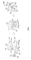
- FIG. 1 illustrates a perspective view of a power inductor having an ER-I shaped-core during multiple stages in the manufacturing process, in accordance with an exemplary embodiment
- FIG. 2 illustrates a perspective view of a power inductor having a U-I shaped-core during multiple stages in the manufacturing process, in accordance with an exemplary embodiment
- FIG. 3A illustrates a perspective view of a symmetrical U core in accordance with an exemplary embodiment
- FIG. 3B illustrates a perspective view of an asymmetrical U core in accordance with an exemplary embodiment
- FIG. 4 illustrates a perspective view of a power inductor having a bead core in accordance with an exemplary embodiment
- FIG. 5 illustrates a perspective view of a power inductor having a plurality of U shaped-cores formed as a single structure in accordance with an exemplary embodiment.
- the device is an inductor, although it is appreciated that the benefits of the invention described below may accrue to other types of devices. While the materials and techniques described below are believed to be particularly advantageous for the manufacture of low profile inductors, it is recognized that the inductor is but one type of electrical component in which the benefits of the invention may be appreciated. Thus, the description set forth is for illustrative purposes only, and it is contemplated that benefits of the invention accrue to other sizes and types of inductors, as well as other electronic components, including but not limited to transformers.
- FIG. 1 illustrates a perspective view of a power inductor having an ER-I shaped-core during multiple stages in the manufacturing process, in accordance with an exemplary embodiment.
- the power inductor 100 comprises an ER core 110 , a preformed coil 130 , and an I core 150 .
- the ER core 110 is generally square or rectangular in shape and has a base 112 , two side walls 114 , 115 , two end walls 120 , 121 , a receptacle 124 , and a centering projection or post 126 .
- the two side walls 114 , 115 extend the entire longitudinal length of the base 112 and have an exterior surface 116 and an interior surface 117 , wherein the interior surface 117 is proximate to the centering projection 126 .
- the exterior surface 116 of the two side walls 114 , 115 are substantially planar, while the interior surface 117 of the two side walls are concave.
- the two end walls 120 , 121 extend a portion of the width of the base 112 from the ends of each side wall 114 , 115 of the base 112 , such that a gap 122 , 123 is formed in each of the two end walls 120 , 121 , respectively.
- This gap 122 , 123 may be formed substantially in the center of each of the two end walls 120 , 121 such that the two side walls 114 , 115 are mirror images of one another.
- the receptacle 124 is defined by the two side walls 114 , 115 and the two end walls 120 , 121 .
- the centering projection 126 may be centrally located in the receptacle 124 of the ER core 110 and may extend upwardly from the base 112 of the ER core 110 .
- the centering projection 126 may extend to a height that is substantially the same as the height of the two side walls 114 , 115 and the two end walls 120 , 121 , or the height may extend less than the height of the two side walls 114 , 115 and the two end walls 120 , 121 .
- the centering projection 126 extends into an inner periphery 132 of the preformed coil 130 to maintain the preformed coil 130 in a fixed, predetermined, and centered position with respect to the ER core 110 .
- the ER core is described as having a symmetrical core structure in this embodiment, the ER core may have an asymmetrical core structure without departing from the scope and spirit of the exemplary embodiment.
- the preformed coil 130 has a coil having one or more turns, and two terminals 134 , 136 , or leads, that extend from the preformed coil 130 at 180° from one another.
- the two terminals 134 , 136 extend in an outwardly direction from the preformed coil 130 , then in an upward direction, and then back in an inward direction towards the preformed coil 130 ; thereby each forming a U-shaped configuration.
- the preformed coil 130 defines the inner periphery 132 of the preformed coil 130 .
- the configuration of the preformed coil 130 is designed to couple the preformed coil 130 to the ER core 110 via the centering projection 126 , such that the centering projection 126 extends into the inner periphery 132 of the preformed coil 130 .
- the preformed coil 130 is fabricated from copper and is plated with nickel and tin. Although the preformed coil 130 is made from copper and has nickel and tin plating, other suitable conductive materials, including but not limited to gold plating and soldering, may be utilized in fabricating the preformed coil 130 and/or the two terminals 134 , 136 without departing from the scope and spirit of the invention. Additionally, although a preformed coil 130 has been depicted as one type of winding that may be used within this embodiment, other types of windings may be utilized without departing from the scope and spirit of the invention. Additionally, although this embodiment utilizes a preformed coil 130 , semi-preformed windings, and non-preformed windings may also be used without departing from the scope and spirit of the invention.
- the terminals 134 , 136 have been described in a particular configuration, alternative configurations may be used for the terminals without departing from the scope and spirit of the invention.
- the geometry of the preformed coil 130 may be circular, square, rectangular, or any other geometric shape without departing from the scope and spirit of the invention.
- the interior surface of the two side walls 114 , 115 and the two end walls 120 , 121 may be reconfigured accordingly to correspond to the geometry of the preformed coil 130 , or winding. In the event the coil 130 has multiple turns, insulation between the turns may be required.
- the insulation may be a coating or other type of insulator that may be placed between the turns.
- the I core 150 is generally square or rectangular in shape and substantially corresponds to the footprint of the ER core 110 .
- the I core 150 has two opposing ends 152 , 154 , wherein each end 152 , 154 has a recessed portion 153 , 155 , respectively, to accommodate an end portion of the terminals 134 , 136 .
- the recessed portions 153 , 155 are substantially the same width, or slightly larger in width, when compared to the width of the end portion of the terminals 134 , 136 .
- the ER core 110 and the I core 150 are both fabricated from an amorphous powder core material.
- the amorphous powder core material can be an iron-based amorphous powder core material.
- One example of the iron-based amorphous powder core material comprises approximately 80% iron and 20% other elements.
- the amorphous powder core material can be a cobalt-based amorphous powder core material.
- One example of the cobalt-based amorphous powder core material comprises approximately 75% cobalt and 25% other elements.
- the amorphous powder core material can be a nanoamorphous powder core material.
- This material provides for a distributed gap structure, wherein the binder material behaves as gaps within the fabricated iron-based amorphous powder material.
- An exemplary material is manufactured by Amosense in Seoul, Korea and sold under product number APHxx (Advanced Powder Core), where xx represents the effective permeability of the material. For example, if the effective permeability for the material is 60, the part number is APH60.
- This material is capable of being used for high current power inductor applications. Additionally, this material may be used with higher operating frequencies, typically in the range of about 1 MHz to about 2 MHz, without producing abnormal heating of the inductor 100 . Although the material may be used in the higher frequency range, the material may be used in lower and higher frequency ranges without departing from the scope and spirit of the invention.
- the amorphous powder core material can provide a higher saturation flux density, a lower hysteresis core loss, a wider operating frequency range, a wider operating temperature range, better heat dissipation and a higher effective permeability. Additionally, this material can provide for a lower loss distributed gap material, which thereby can maximize the power and energy density.
- the effective permeability of shaped-cores is not very high due to pressing density concerns. However, use of this material for the shaped-cores can allow a much higher effective permeability than previously available.
- the nanoamorphous powder material can allow up to three times higher permeability when compared to the permeability of an iron-based amorphous powder material.
- the ER core 110 and the I core 150 are pressed molded from amorphous powder material to form the solid shaped-cores.
- the preformed coil 130 is coupled to the ER core 110 in the manner previously described.
- the terminals 134 , 136 of the preformed coil 130 extend through the gaps 122 , 123 in the two end walls 120 , 121 .
- the I core 150 is then coupled to the ER core 110 and the preformed coil 130 such that the ends of the terminals 134 , 136 are coupled within the recessed portions 153 , 155 , respectively, of the I core 150 .
- the ER core 110 , the preformed coil 130 , and the I core 150 are then pressed molded together to form the ER-I inductor 100 .
- the I core 150 has been illustrated as having recessed portions 153 , 155 formed in the two opposing ends 152 , 154 , the I core 150 may have the recessed portions omitted without departing from the scope and spirit of the invention.
- the I core 150 has been illustrated to be symmetrical, asymmetrical I cores may be used, including I cores having mistake proofing, as described below, without departing from the scope and spirit of the invention.
- FIG. 2 illustrates a perspective view of a power inductor having a U-I shaped-core, during multiple stages in the manufacturing process, in accordance with an exemplary embodiment.
- the power inductor 200 comprises a U core 210 , a preformed clip 230 , and an I core 250 .
- the U core 210 has two sides 212 , 214 and two ends 216 , 218 , wherein the two sides 212 , 214 are parallel with respect to the orientation of the winding, or clip, 230 and the two ends 216 , 218 are perpendicular with respect to the orientation of the winding, or clip 230 .
- the I core 250 has two sides 252 , 254 and two ends 256 , 260 , wherein the two sides 252 , 254 are parallel with respect to the orientation of the winding, or clip, 230 and the two ends 256 , 260 are perpendicular with respect to the orientation of the winding, or clip 230 .
- the I core 250 has been modified to provide for a mistake proof I core 250 .
- the mistake proof I core 250 has removed portions 257 , 261 from two parallel ends 256 , 260 , respectively at one side 252 of the bottom 251 of the mistake proof I core 250 and non-removed portions 258 , 262 from the same two parallel ends 256 , 260 , respectively, at the opposing side 254 of the mistake proof I core 250 .
- the preformed clip 230 has two terminals 234 , 236 , or leads, that may be coupled around the mistake proof I core 250 by positioning the preformed clip 230 at the removed portions 257 , 261 and sliding the preformed clip 230 towards the non-removed portions 258 , 262 until the preformed clip 230 may not be moved further.
- the preformed clip 230 can allow better DCR control, when compared to a non-preformed clip, because bending and cracking of platings is greatly reduced in the manufacturing process.
- the mistake proof I core 250 enables the preformed clip 230 to be properly positioned so that the U core 210 may be quickly, easily, and correctly coupled to the mistake proof I core 250 . As shown in FIG.
- the mistake proof I core 250 provides the mistake proofing.
- alternative sides may provide the mistake proofing without departing from the scope and spirit of the exemplary embodiment.
- the mistake proofing may be located only at the opposing ends 256 , 260 or at the opposing ends 256 , 260 and the bottom 251 of the I core, instead of only at the bottom 251 of the I core 250 as depicted in FIG. 2 .
- the I core 250 may be formed without any mistake proofing according some alternative embodiments.
- the preformed clip 230 is fabricated from copper and is plated with nickel and tin. Although the preformed clip 230 is made from copper and has nickel and tin plating, other suitable conductive materials, including but not limited to gold plating and soldering, may be utilized in fabricating the preformed clip 230 and/or the two terminals 234 , 236 without departing from the scope and spirit of the invention. Additionally, although a preformed clip 230 is used in this embodiment, the clip 230 may be partially preformed or not preformed without departing from the scope and spirit of the invention. Furthermore, although a preformed clip 230 is depicted in this embodiment, any form of winding may be used without departing from the scope and spirit of the invention.
- the removed portions 257 , 261 from the mistake proof I core 250 may be dimensioned such that a symmetrical U core or an asymmetrical U core, which are described with respect to FIG. 3A and FIG. 3B respectively, may be utilized without departing from the scope and spirit of the invention.
- the U core 210 is dimensioned to have a width substantially the same as the width of the mistake proof I core 250 and a length substantially the same as the length of the mistake proof I core 250 . Although the dimensions of the U core 210 have been illustrated above, the dimensions may be altered without departing from the scope and spirit of the invention.
- FIG. 3A illustrates a perspective view of a symmetrical U core in accordance with an exemplary embodiment.
- the symmetrical U core 300 has one surface 310 and an opposing surface 320 , wherein the one surface 310 is substantially planar, and the opposing surface 320 has a first leg 322 , a second leg 324 , and a clip channel 326 defined between the first leg 322 and the second leg 324 .
- the width of the first leg 322 is substantially equal to the width of the second leg 324 .
- This symmetrical U core 300 is coupled to the I core 250 , and a portion of the preformed clip 230 is positioned within the clip channel 326 .
- the terminals 234 , 236 of the preformed clip 230 are coupled to the bottom surface 251 of the I core 250 .
- the terminals 234 , 236 of the preformed clip 230 may be coupled to the one surface 310 of the U core 300 .
- FIG. 3B illustrates a perspective view of an asymmetrical U core in accordance with an exemplary embodiment.
- the asymmetrical U core 350 has one surface 360 and an opposing surface 370 , wherein the one surface 360 is substantially planar, and the opposing surface 370 has a first leg 372 , a second leg 374 , and a clip channel 376 defined between the first leg 372 and the second leg 374 .
- the width of the first leg 372 is not substantially equal to the width of the second leg 374 .
- This asymmetrical U core 350 is coupled to the I core 250 , and a portion of the preformed clip 230 is positioned within the clip channel 376 .
- the terminals 234 , 236 of the preformed clip 230 are coupled to the bottom surface 251 of the I core 250 .
- the terminals 234 , 236 of the preformed clip 230 may be coupled to the one surface 360 of the U core 350 .
- One reason for using an asymmetrical U core 350 is to provide a more even flux density distribution throughout the entire magnetic path.
- the U core 210 and the I core 250 are both fabricated from an amorphous powder core material, which is the same material as described above in reference to the ER core 110 and the I core 150 .
- the amorphous powder core material can be an iron-based amorphous powder core material. Additionally, a nanoamorphous powder material may also be used for these core materials.
- the preformed clip 230 is coupled to the I core 250
- the U core 210 is coupled to the I core 250 and the preformed clip 230 such that the preformed clip 230 is positioned within the clip channel of the U core 210 .
- the U core 210 can be symmetrical as shown with U core 310 or asymmetrical as shown with U core 350 .
- the U core 210 , the preformed clip 230 , and the I core 250 are then pressed molded together to form the UI inductor 200 .
- the press molding removes the physical gap that is generally located between the preformed clip 230 and the core 210 , 250 by having the cores 210 , 250 form molded around the preformed clip 230 .
- FIG. 4 illustrates a perspective view of a power inductor having a bead core in accordance with an exemplary embodiment.
- the power inductor 400 comprises a bead core 410 and a semi-preformed clip 430 .
- the bead core 410 has two sides 412 , 414 and two ends 416 , 418 , wherein the two sides 412 , 414 are parallel with respect to the winding, or clip, 430 and the two ends 416 , 418 are perpendicular with respect to the winding, or clip 430 .
- the bead core 410 is fabricated from an amorphous powder core material, which is the same material as described above in reference to the ER core 110 and the I core 150 .
- the amorphous powder core material can be an iron-based amorphous powder core material. Additionally, a nanoamorphous powder material may also be used for these core materials.
- the semi-preformed clip 430 comprises two terminals, or leads, 434 , 436 at opposing two ends 416 , 418 and may be coupled to the bead core 410 by having a portion of the semi-preformed clip 430 pass centrally within the bead core 410 and having the two terminals 434 , 436 wrap around the two ends 416 , 418 of the bead core 410 .
- the semi-preformed clip 430 can allow better DCR control, when compared to a non-preformed clip, because bending and cracking of platings is greatly reduced in the manufacturing process.
- the semi-preformed clip 430 is fabricated from copper and is plated with nickel and tin. Although the semi-preformed clip 430 is made from copper and has nickel and tin plating, other suitable conductive materials, including but not limited to gold plating and soldering, may be utilized in fabricating the semi-preformed clip 430 without departing from the scope and spirit of the invention. Additionally, although a semi-preformed clip 430 is used in this embodiment, the clip 430 may be not preformed without departing from the scope and spirit of the invention. Furthermore, although a semi-preformed clip 430 is depicted in this embodiment, any form of winding may be used without departing from the scope and spirit of the invention.
- the semi-preformed clip 430 is coupled to the bead core 410 by having a portion of the semi-preformed clip 430 pass within the bead core 410 and having the two terminals 434 , 436 wrap around the two ends 416 , 418 of the bead core 410 .
- the bead core 410 can be modified to have a removed portion 440 from one side 412 of the bottom 450 of the bead core 410 and a non-removed portion 442 from the opposing side 414 of the bead core 410 .
- the two terminals 434 , 436 of the semi-preformed clip 430 can be positioned at the bottom 450 of the bead core 410 such that the terminals 434 , 436 are located within the removed portion 442 .
- the bead core has been illustrated having a removed portion and a non-removed portion, the bead core may be formed to omit the removed portion without departing from the scope and spirit of the invention.
- the amorphous powder core material may be initially formed into a sheet and then wrapped or rolled around the semi-preformed clip 430 .
- the amorphous powder core material and the semi-preformed clip 430 can then be pressed at high pressures, thereby forming the power inductor 400 .
- the press molding removes the physical gap that is generally located between the semi-preformed clip 430 and the bead core 410 by having the bead core 410 form molded around the semi-preformed clip 430 .
- the amorphous powder core material and the semi-preformed clip 430 may be positioned within a mold (not shown), such that the amorphous powder core material surrounds at least a portion of the semi-preformed clip 430 .
- the amorphous powder core material and the semi-preformed clip 430 can then be pressed at high pressures, thereby forming the power inductor 400 .
- the press molding removes the physical gap that is generally located between the semi-preformed clip 430 and the bead core 410 by having the bead core 410 form molded around the semi-preformed clip 430 .
- a bead core may be formed by pressing the amorphous powder core material at high pressures, followed by coupling the winding to the bead core, and then followed by adding additional amorphous powder core material to the bead core so that the winding is disposed between the bead core and at least a portion of the additional amorphous powder core material.
- the bead core, the winding and the additional amorphous powder core material are then pressed together at high pressures to form the power inductor described in this embodiment.
- two discrete shaped cores may be formed by pressing the amorphous powder core material at high pressures, followed by positioning the winding between the two discrete shaped cores, and then followed by adding additional amorphous powder core material.
- the two discrete shaped cores, the winding, and the additional amorphous powder core material are then pressed together at high pressures to form the power inductor described in this embodiment.
- injection molding can be used to mold the amorphous powder core material and the winding together.
- FIG. 5 illustrates a perspective view of a power inductor having a plurality of U shaped-cores formed as a single structure in accordance with an exemplary embodiment.
- the power inductor 500 comprises four U shaped-cores 510 , 515 , 520 , 525 formed as a single structure 505 and four clips 530 , 532 , 534 , 536 , wherein each clip 530 , 532 , 534 , 536 is coupled to a respective one of the U shaped-core 510 , 515 , 520 , 525 and wherein each clip 530 , 532 , 534 , 536 is not preformed.
- the inductor 500 has two sides 502 , 504 and two ends 506 , 508 , wherein the two sides 502 , 504 are parallel with respect to the windings, or clips, 530 , 532 , 534 , 536 , and the two ends 506 , 508 are perpendicular with respect to the windings, or clips, 530 , 532 , 534 , 536 .
- U cores 510 , 515 , 520 , 525 and four clips 530 , 532 , 534 , 536 are shown to form a single structure 505 , greater or fewer U cores, with a corresponding number of clips, may be used to form the single structure without departing from the scope and spirit of the invention.
- the core material is fabricated from an iron-based amorphous powder core material, which is the same material as described above in reference to the ER core 110 and the I core 150 . Additionally, a nanoamorphous powder material may also be used for these core materials.
- Each clip 530 , 532 , 534 , 536 has two terminals, or leads, 540 (not shown), 542 at opposing ends and may be coupled to each of the U shaped-cores 510 , 515 , 520 , 525 by having a portion of the clip 530 , 532 , 534 , 536 pass centrally within each of the U shaped-cores 510 , 515 , 520 , 525 and having the two terminals 540 (not shown), 542 of each clip 530 , 532 , 534 , 536 wrap around the two ends 506 , 508 of the inductor 500 .
- the clips 530 , 532 , 534 , 536 are fabricated from copper and are plated with nickel and tin. Although the clips 530 , 532 , 534 , 536 are made from copper and has nickel and tin plating, other suitable conductive materials, including but not limited to gold plating and soldering, may be utilized in fabricating the clips without departing from the scope and spirit of the invention. Additionally, although the clips 530 , 532 , 534 , 536 are depicted in this embodiment, any form of windings may be used without departing from the scope and spirit of the invention.
- the clips 530 , 532 , 534 , 536 are coupled to the U shaped-cores 510 , 515 , 520 , 525 by having a portion of each of the clips 530 , 532 , 534 , 536 pass within each of the U shaped-cores 510 , 515 , 520 , 525 and having the two terminals 540 (not shown), 542 of each preformed clip 530 , 532 , 534 , 536 wrap around the two ends 506 , 508 of the inductor 500 .
- the amorphous powder core material may be initially formed into a sheet and then wrapped around the clips 530 , 532 , 534 , 536 .
- the amorphous powder core material and the clips 530 , 532 , 534 , 536 can then be pressed at high pressures, thereby forming the U-shaped inductor 500 having a plurality of U shaped-cores 510 , 515 , 520 , 525 formed as a single structure 505 .
- the press molding removes the physical gap that is generally located between the clips 530 , 532 , 534 , 536 and the cores 510 , 515 , 520 , 525 by having the cores 510 , 515 , 520 , 525 form molded around the clips 530 , 532 , 534 , 536 .
- the amorphous powder core material and the clips 530 , 532 , 534 , 536 may be positioned within a mold (not shown), such that the amorphous powder core material surrounds at least a portion of the clips 530 , 532 , 534 , 536 .
- the amorphous powder core material and the clips 530 , 532 , 534 , 536 can then be pressed at high pressures, thereby forming the U-shaped inductor 500 having a plurality of U shaped-cores 510 , 515 , 520 , 525 formed as a single structure 505 .
- the press molding removes the physical gap that is generally located between the clips 530 , 532 , 534 , 536 and the cores 510 , 515 , 520 , 525 by having the cores 510 , 515 , 520 , 525 form molded around the clips 530 , 532 , 534 , 536 .
- a plurality of U-shaped cores may be formed together by pressing the amorphous powder core material at high pressures, followed by coupling the plurality of windings to each of the plurality of U-shaped cores, and then followed by adding additional amorphous powder core material to the plurality of U-shaped cores so that the plurality of windings are disposed between the plurality of U-shaped cores and at least a portion of the additional amorphous powder core material.
- the plurality of U-shaped cores, the plurality of windings, and the additional amorphous powder core material are then pressed together at high pressures to form the inductor described in this embodiment.
- two discrete shaped cores wherein each discrete shaped core has a plurality of shaped cores coupled together, may be formed by pressing the amorphous powder core material at high pressures, followed by positioning the plurality of windings between the two discrete shaped cores, and then followed by adding additional amorphous powder core material.
- the two discrete shaped cores, the plurality of windings, and the additional amorphous powder core material are then pressed together at high pressures to form the inductor described in this embodiment.
- injection molding can be used to mold the amorphous powder core material and the plurality of windings together.
- the plurality of clips 530 , 532 , 534 , 536 may be connected in parallel to each other or in series based upon circuit connections on a substrate (not shown) and depending upon application requirements. Furthermore, these clips 530 , 532 , 534 , 536 may be designed to accommodate multi-phase current, for example, three-phase and four-phase.
Abstract
Description
Claims (14)
Priority Applications (13)
| Application Number | Priority Date | Filing Date | Title |
|---|---|---|---|
| US12/247,821 US8310332B2 (en) | 2008-10-08 | 2008-10-08 | High current amorphous powder core inductor |
| US12/535,981 US8400245B2 (en) | 2008-07-11 | 2009-08-05 | High current magnetic component and methods of manufacture |
| JP2011531055A JP5985825B2 (en) | 2008-10-08 | 2009-09-18 | High current amorphous powder core inductor |
| MX2010013934A MX2010013934A (en) | 2008-10-08 | 2009-09-18 | High current amorphous powder core inductor. |
| PCT/US2009/057471 WO2010042308A1 (en) | 2008-10-08 | 2009-09-18 | High current amorphous powder core inductor |
| EP09792712A EP2345046A1 (en) | 2008-10-08 | 2009-09-18 | High current amorphous powder core inductor |
| KR1020107029174A KR101536376B1 (en) | 2008-10-08 | 2009-09-18 | High current amorphous powder core inductor |
| CN200980129985.5A CN102105953B (en) | 2008-10-08 | 2009-09-18 | High current amorphous powder core inductor |
| CA2726727A CA2726727A1 (en) | 2008-10-08 | 2009-09-18 | High current amorphous powder core inductor |
| TW098133874A TW201019351A (en) | 2008-10-08 | 2009-10-06 | High current amorphous powder core inductor |
| US12/765,115 US9859043B2 (en) | 2008-07-11 | 2010-04-22 | Magnetic components and methods of manufacturing the same |
| US13/709,793 US9275787B2 (en) | 2006-09-12 | 2012-12-10 | High current magnetic component and methods of manufacture |
| US14/217,705 US9558881B2 (en) | 2008-07-11 | 2014-03-18 | High current power inductor |
Applications Claiming Priority (1)
| Application Number | Priority Date | Filing Date | Title |
|---|---|---|---|
| US12/247,821 US8310332B2 (en) | 2008-10-08 | 2008-10-08 | High current amorphous powder core inductor |
Related Child Applications (2)
| Application Number | Title | Priority Date | Filing Date |
|---|---|---|---|
| US12/535,981 Continuation-In-Part US8400245B2 (en) | 2006-09-12 | 2009-08-05 | High current magnetic component and methods of manufacture |
| US12/765,115 Continuation-In-Part US9859043B2 (en) | 2008-07-11 | 2010-04-22 | Magnetic components and methods of manufacturing the same |
Publications (2)
| Publication Number | Publication Date |
|---|---|
| US20100085139A1 US20100085139A1 (en) | 2010-04-08 |
| US8310332B2 true US8310332B2 (en) | 2012-11-13 |
Family
ID=41314615
Family Applications (1)
| Application Number | Title | Priority Date | Filing Date |
|---|---|---|---|
| US12/247,821 Expired - Fee Related US8310332B2 (en) | 2006-09-12 | 2008-10-08 | High current amorphous powder core inductor |
Country Status (9)
| Country | Link |
|---|---|
| US (1) | US8310332B2 (en) |
| EP (1) | EP2345046A1 (en) |
| JP (1) | JP5985825B2 (en) |
| KR (1) | KR101536376B1 (en) |
| CN (1) | CN102105953B (en) |
| CA (1) | CA2726727A1 (en) |
| MX (1) | MX2010013934A (en) |
| TW (1) | TW201019351A (en) |
| WO (1) | WO2010042308A1 (en) |
Cited By (14)
| Publication number | Priority date | Publication date | Assignee | Title |
|---|---|---|---|---|
| US20120081204A1 (en) * | 2011-11-03 | 2012-04-05 | Paul Garrity | Transformer construction |
| US20140266555A1 (en) * | 2013-03-15 | 2014-09-18 | Cooper Technologies Company | Magnetic component assembly with filled gap |
| US20150145911A1 (en) * | 2013-11-27 | 2015-05-28 | Seiko Epson Corporation | Liquid ejecting apparatus |
| US20150187487A1 (en) * | 2014-01-02 | 2015-07-02 | Samsung Electro-Mechanics Co., Ltd. | Ceramic electronic component |
| USD741261S1 (en) | 2011-12-28 | 2015-10-20 | Toko, Inc. | Inductor |
| US9202617B2 (en) | 2013-07-03 | 2015-12-01 | Cooper Technologies Company | Low profile, surface mount electromagnetic component assembly and methods of manufacture |
| US9558881B2 (en) | 2008-07-11 | 2017-01-31 | Cooper Technologies Company | High current power inductor |
| US10325715B2 (en) | 2016-10-06 | 2019-06-18 | Eaton Intelligent Power Limited | Low profile electromagnetic component |
| US10840005B2 (en) | 2013-01-25 | 2020-11-17 | Vishay Dale Electronics, Llc | Low profile high current composite transformer |
| US10854367B2 (en) | 2016-08-31 | 2020-12-01 | Vishay Dale Electronics, Llc | Inductor having high current coil with low direct current resistance |
| US10998124B2 (en) | 2016-05-06 | 2021-05-04 | Vishay Dale Electronics, Llc | Nested flat wound coils forming windings for transformers and inductors |
| US11476040B2 (en) | 2019-10-28 | 2022-10-18 | Eaton Intelligent Power Limited | Ultra-narrow high current power inductor for circuit board applications |
| US11823828B2 (en) | 2021-08-26 | 2023-11-21 | Chilisin Electronics Corp. | Inductive device and method of manufacturing the same |
| US11948724B2 (en) | 2021-06-18 | 2024-04-02 | Vishay Dale Electronics, Llc | Method for making a multi-thickness electro-magnetic device |
Families Citing this family (31)
| Publication number | Priority date | Publication date | Assignee | Title |
|---|---|---|---|---|
| US8941457B2 (en) | 2006-09-12 | 2015-01-27 | Cooper Technologies Company | Miniature power inductor and methods of manufacture |
| US7791445B2 (en) | 2006-09-12 | 2010-09-07 | Cooper Technologies Company | Low profile layered coil and cores for magnetic components |
| US8466764B2 (en) * | 2006-09-12 | 2013-06-18 | Cooper Technologies Company | Low profile layered coil and cores for magnetic components |
| US9589716B2 (en) | 2006-09-12 | 2017-03-07 | Cooper Technologies Company | Laminated magnetic component and manufacture with soft magnetic powder polymer composite sheets |
| US8378777B2 (en) | 2008-07-29 | 2013-02-19 | Cooper Technologies Company | Magnetic electrical device |
| US8076617B2 (en) * | 2007-04-06 | 2011-12-13 | Norwood Robert A | Nanoamorphous carbon-based photonic crystal infrared emitters |
| US8659379B2 (en) | 2008-07-11 | 2014-02-25 | Cooper Technologies Company | Magnetic components and methods of manufacturing the same |
| US9859043B2 (en) | 2008-07-11 | 2018-01-02 | Cooper Technologies Company | Magnetic components and methods of manufacturing the same |
| WO2010060837A1 (en) * | 2008-11-28 | 2010-06-03 | Osram Gesellschaft mit beschränkter Haftung | Integrated gas discharge lamp and ignition transformer for an integrated gas discharge lamp |
| US20100277267A1 (en) * | 2009-05-04 | 2010-11-04 | Robert James Bogert | Magnetic components and methods of manufacturing the same |
| TWI581384B (en) * | 2009-12-07 | 2017-05-01 | 英特希爾美國公司 | Stacked inductor-electronic package assembly and technique for manufacturing same |
| JP4800451B1 (en) * | 2011-06-10 | 2011-10-26 | 株式会社精電製作所 | High frequency transformer |
| GB201120955D0 (en) * | 2011-12-06 | 2012-01-18 | Isotera Ltd | A coupler for use in a power distribution system |
| CN103187144A (en) * | 2011-12-31 | 2013-07-03 | 台达电子企业管理(上海)有限公司 | Magnetic element and manufacturing method thereof |
| JP6097962B2 (en) * | 2012-04-12 | 2017-03-22 | パナソニックIpマネジメント株式会社 | Power conversion transformer, vehicle headlamp having the power conversion transformer, and vehicle having the vehicle headlamp |
| CN104995698A (en) * | 2013-02-13 | 2015-10-21 | 株式会社村田制作所 | Electronic component |
| CN104051128B (en) * | 2013-03-15 | 2018-03-30 | 库柏技术公司 | High-performance high current power inductor |
| JP6245263B2 (en) | 2013-07-08 | 2017-12-13 | 株式会社村田製作所 | Coil parts |
| US9711279B2 (en) | 2013-10-28 | 2017-07-18 | Infineon Technologies Austria Ag | DC-DC converter assembly with an output inductor accommodating a power stage attached to a circuit board |
| US9653205B2 (en) * | 2014-04-30 | 2017-05-16 | Cyntec Co., Ltd. | Electrode structure and the corresponding electrical component using the same and the fabrication method thereof |
| US9831023B2 (en) * | 2014-07-10 | 2017-11-28 | Cyntec Co., Ltd. | Electrode structure and the corresponding electrical component using the same and the fabrication method thereof |
| US10546684B2 (en) * | 2014-08-21 | 2020-01-28 | Cyntec Co., Ltd | Integrally-formed inductor |
| US9387295B1 (en) * | 2015-01-30 | 2016-07-12 | SurgiQues, Inc. | Filter cartridge with internal gaseous seal for multimodal surgical gas delivery system having a smoke evacuation mode |
| US10763028B2 (en) | 2015-04-10 | 2020-09-01 | Delta Electronics, Inc. | Magnetic component and magnetic core of the same |
| TWI557759B (en) * | 2015-04-10 | 2016-11-11 | 台達電子工業股份有限公司 | Integrated inductor and integrated inductor magnetic core of the same |
| US10333407B2 (en) | 2015-05-06 | 2019-06-25 | Infineon Technologies Austria Ag | Power stage packages of a multi-phase DC-DC converter under a coupled inductor |
| US10855178B2 (en) | 2015-05-29 | 2020-12-01 | Infineon Technologies Austria Ag | Discrete power stage transistor dies of a DC-DC converter under an inductor |
| CN106601419B (en) * | 2016-11-18 | 2019-04-16 | 日照亿鑫电子材料有限公司 | A kind of magnetic material and preparation method with interstitial structure |
| KR20180064186A (en) | 2016-12-05 | 2018-06-14 | 삼성전기주식회사 | Coil component |
| JP6819632B2 (en) * | 2018-03-01 | 2021-01-27 | 株式会社村田製作所 | Surface mount inductor |
| US20230371165A1 (en) * | 2022-05-12 | 2023-11-16 | Infineon Technologies Austria Ag | Voltage regulator module with inductor-cooled power stage |
Citations (120)
| Publication number | Priority date | Publication date | Assignee | Title |
|---|---|---|---|---|
| US2391563A (en) | 1943-05-18 | 1945-12-25 | Super Electric Products Corp | High frequency coil |
| US3255512A (en) | 1962-08-17 | 1966-06-14 | Trident Engineering Associates | Molding a ferromagnetic casing upon an electrical component |
| US4072780A (en) | 1976-10-28 | 1978-02-07 | Varadyne Industries, Inc. | Process for making electrical components having dielectric layers comprising particles of a lead oxide-germanium dioxide-silicon dioxide glass and a resin binder therefore |
| US4313152A (en) | 1979-01-12 | 1982-01-26 | U.S. Philips Corporation | Flat electric coil |
| US4543553A (en) | 1983-05-18 | 1985-09-24 | Murata Manufacturing Co., Ltd. | Chip-type inductor |
| US4689594A (en) | 1985-09-11 | 1987-08-25 | Murata Manufacturing Co., Ltd. | Multi-layer chip coil |
| US4750077A (en) | 1983-03-01 | 1988-06-07 | Mitsubishi Denki Kabushiki Kaisha | Coil device |
| US4758808A (en) | 1983-08-16 | 1988-07-19 | Tdk Corporation | Impedance element mounted on a pc board |
| US4803425A (en) | 1987-10-05 | 1989-02-07 | Xerox Corporation | Multi-phase printed circuit board tachometer |
| US4873757A (en) | 1987-07-08 | 1989-10-17 | The Foxboro Company | Method of making a multilayer electrical coil |
| US5032815A (en) | 1988-12-23 | 1991-07-16 | Murata Manufacturing Co., Ltd. | Lamination type inductor |
| US5045380A (en) | 1988-08-24 | 1991-09-03 | Murata Manufacturing Co., Ltd. | Lamination type inductor |
| US5250923A (en) | 1992-01-10 | 1993-10-05 | Murata Manufacturing Co., Ltd. | Laminated chip common mode choke coil |
| US5257000A (en) | 1992-02-14 | 1993-10-26 | At&T Bell Laboratories | Circuit elements dependent on core inductance and fabrication thereof |
| US5300911A (en) | 1991-07-10 | 1994-04-05 | International Business Machines Corporation | Monolithic magnetic device with printed circuit interconnections |
| EP0655754A1 (en) | 1993-11-25 | 1995-05-31 | Mitsui Petrochemical Industries, Ltd. | Inductance element |
| US5463717A (en) | 1989-07-10 | 1995-10-31 | Yozan Inc. | Inductively coupled neural network |
| US5500629A (en) | 1993-09-10 | 1996-03-19 | Meyer Dennis R | Noise suppressor |
| US5515022A (en) | 1991-05-13 | 1996-05-07 | Tdk Corporation | Multilayered inductor |
| US5532667A (en) | 1992-07-31 | 1996-07-02 | Hughes Aircraft Company | Low-temperature-cofired-ceramic (LTCC) tape structures including cofired ferromagnetic elements, drop-in components and multi-layer transformer |
| US5572180A (en) | 1995-11-16 | 1996-11-05 | Motorola, Inc. | Surface mountable inductor |
| JP2700713B2 (en) | 1990-09-05 | 1998-01-21 | 株式会社トーキン | Inductor |
| US5761791A (en) | 1993-12-24 | 1998-06-09 | Murata Manufacturing Co., Ltd. | Method of manufacturing a chip transformer |
| US5821638A (en) | 1993-10-21 | 1998-10-13 | Auckland Uniservices Limited | Flux concentrator for an inductive power transfer system |
| US5849355A (en) | 1996-09-18 | 1998-12-15 | Alliedsignal Inc. | Electroless copper plating |
| US5875541A (en) | 1992-10-12 | 1999-03-02 | Matsushita Electric Industrial Co., Ltd. | Method of manufacturing an electronic component |
| US5945902A (en) | 1997-09-22 | 1999-08-31 | Zefv Lipkes | Core and coil structure and method of making the same |
| US6038134A (en) | 1996-08-26 | 2000-03-14 | Johanson Dielectrics, Inc. | Modular capacitor/inductor structure |
| US6054914A (en) | 1998-07-06 | 2000-04-25 | Midcom, Inc. | Multi-layer transformer having electrical connection in a magnetic core |
| US6114939A (en) | 1999-06-07 | 2000-09-05 | Technical Witts, Inc. | Planar stacked layer inductors and transformers |
| JP3108931B2 (en) | 1991-03-15 | 2000-11-13 | 株式会社トーキン | Inductor and manufacturing method thereof |
| US6169801B1 (en) | 1998-03-16 | 2001-01-02 | Midcom, Inc. | Digital isolation apparatus and method |
| KR20010014533A (en) | 1999-03-09 | 2001-02-26 | 사토 히로시 | Method for the Preparation of Soft Magnetic Ferrite Powder and Method for the Production of Laminated Chip Inductor |
| US6198374B1 (en) | 1999-04-01 | 2001-03-06 | Midcom, Inc. | Multi-layer transformer apparatus and method |
| US6198375B1 (en) | 1999-03-16 | 2001-03-06 | Vishay Dale Electronics, Inc. | Inductor coil structure |
| US6204744B1 (en) | 1995-07-18 | 2001-03-20 | Vishay Dale Electronics, Inc. | High current, low profile inductor |
| JP3160685B2 (en) | 1992-04-14 | 2001-04-25 | 株式会社トーキン | Inductor |
| US20010016977A1 (en) | 2000-01-12 | 2001-08-30 | Tdk Corporation | Coil-embedded dust core production process, and coil-embedded dust core |
| US6287931B1 (en) | 1998-12-04 | 2001-09-11 | Winbond Electronics Corp. | Method of fabricating on-chip inductor |
| US6293001B1 (en) | 1994-09-12 | 2001-09-25 | Matsushita Electric Industrial Co., Ltd. | Method for producing an inductor |
| EP1150312A2 (en) | 2000-04-28 | 2001-10-31 | Matsushita Electric Industrial Co., Ltd. | Composite magnetic body, and magnetic element and method of manufacturing the same |
| US20010043135A1 (en) | 2000-05-16 | 2001-11-22 | Katsuo Yamada | Inductor |
| US6366192B2 (en) | 1997-09-17 | 2002-04-02 | Vishay Dale Electronics, Inc. | Structure of making a thick film low value high frequency inductor |
| US6392525B1 (en) | 1998-12-28 | 2002-05-21 | Matsushita Electric Industrial Co., Ltd. | Magnetic element and method of manufacturing the same |
| US6420953B1 (en) | 2000-05-19 | 2002-07-16 | Pulse Engineering. Inc. | Multi-layer, multi-functioning printed circuit board |
| KR20020071285A (en) | 2001-03-06 | 2002-09-12 | (주)창성 | Composite metal powder for power factor correction having good dc biased characteristics and method of processing soft magnetic core by thereof using |
| US20030029830A1 (en) | 2000-12-28 | 2003-02-13 | Tdk Corp. | Method for producing multilayer substrate and electronic part, and multilayer electronic part |
| US6566731B2 (en) | 1999-02-26 | 2003-05-20 | Micron Technology, Inc. | Open pattern inductor |
| US6628531B2 (en) | 2000-12-11 | 2003-09-30 | Pulse Engineering, Inc. | Multi-layer and user-configurable micro-printed circuit board |
| US20030184423A1 (en) | 2002-03-27 | 2003-10-02 | Holdahl Jimmy D. | Low profile high current multiple gap inductor assembly |
| KR20030081738A (en) | 2002-04-12 | 2003-10-22 | 휴먼일렉스(주) | Method of manufacturing soft magnetic powder and inductor using the same |
| US6658724B2 (en) | 1999-12-16 | 2003-12-09 | Tdk Corporation | Powder for magnetic ferrite, magnetic ferrite, multilayer ferrite components and production method thereof |
| US20040017276A1 (en) | 2002-07-25 | 2004-01-29 | Meng-Feng Chen | Inductor module including plural inductor winding sections connected to a common contact and wound on a common inductor core |
| US6713162B2 (en) | 2000-05-31 | 2004-03-30 | Tdk Corporation | Electronic parts |
| US6720074B2 (en) | 2000-10-26 | 2004-04-13 | Inframat Corporation | Insulator coated magnetic nanoparticulate composites with reduced core loss and method of manufacture thereof |
| US6749827B2 (en) | 1997-03-07 | 2004-06-15 | William Marsh Rice University | Method for growing continuous fiber |
| US6750723B2 (en) | 2000-03-21 | 2004-06-15 | Alps Electric Co., Ltd. | Low-loss magnetic powder core, and switching power supply, active filter, filter, and amplifying device using the same |
| US20040174239A1 (en) | 2001-02-21 | 2004-09-09 | Tdk Corporation | Coil-embedded dust core and method for manufacturing the same |
| US6794052B2 (en) | 1994-10-18 | 2004-09-21 | The Regents Of The University Of California | Polymer arrays from the combinatorial synthesis of novel materials |
| US6797336B2 (en) | 2001-03-22 | 2004-09-28 | Ambp Tech Corporation | Multi-component substances and processes for preparation thereof |
| US20040210289A1 (en) | 2002-03-04 | 2004-10-21 | Xingwu Wang | Novel nanomagnetic particles |
| US6817085B2 (en) | 1999-07-07 | 2004-11-16 | Tdk Corporation | Method of manufacturing a multi-layer ferrite chip inductor array |
| EP1486991A1 (en) | 2003-06-12 | 2004-12-15 | Nec Tokin Corporation | Magnetic core and coil component using the same |
| US6835889B2 (en) | 2001-09-21 | 2004-12-28 | Kabushiki Kaisha Toshiba | Passive element component and substrate with built-in passive element |
| WO2005008692A2 (en) | 2003-07-08 | 2005-01-27 | Pulse Engineering, Inc. | Form-less electronic device and methods of manufacturing |
| US6879238B2 (en) | 2003-05-28 | 2005-04-12 | Cyntec Company | Configuration and method for manufacturing compact high current inductor coil |
| US6882261B2 (en) | 2002-01-31 | 2005-04-19 | Tdk Corporation | Coil-embedded dust core and method for manufacturing the same, and coil and method for manufacturing the same |
| US6885276B2 (en) | 2000-03-15 | 2005-04-26 | Murata Manufacturing Co., Ltd. | Photosensitive thick film composition and electronic device using the same |
| EP1526556A1 (en) | 2003-10-21 | 2005-04-27 | Yun-Kuang Fan | Ferrite cored coil structure for SMD and fabrication method of the same |
| US6908960B2 (en) | 1999-12-28 | 2005-06-21 | Tdk Corporation | Composite dielectric material, composite dielectric substrate, prepreg, coated metal foil, molded sheet, composite magnetic substrate, substrate, double side metal foil-clad substrate, flame retardant substrate, polyvinylbenzyl ether resin composition, thermosettin |
| US20050151614A1 (en) | 2003-11-17 | 2005-07-14 | Majid Dadafshar | Inductive devices and methods |
| US6927738B2 (en) | 2001-01-11 | 2005-08-09 | Hanex Co., Ltd. | Apparatus and method for a communication device |
| US20050174207A1 (en) | 2002-03-27 | 2005-08-11 | Commergy Technologies Limited | Magnetic structure assembly |
| EP1564761A1 (en) | 2003-09-01 | 2005-08-17 | Murata Manufacturing Co., Ltd. | Laminated coil component and method of producing the same |
| US6952355B2 (en) | 2002-07-22 | 2005-10-04 | Ops Power Llc | Two-stage converter using low permeability magnetics |
| US6971391B1 (en) | 2002-12-18 | 2005-12-06 | Nanoset, Llc | Protective assembly |
| US20060038651A1 (en) | 2004-08-20 | 2006-02-23 | Alps Electric Co., Ltd. | Coil-embedded dust core |
| US20060049906A1 (en) | 2004-09-08 | 2006-03-09 | Cyntec Company | Configuration and method to manufacture compact inductor coil with low production cost |
| US7019391B2 (en) | 2004-04-06 | 2006-03-28 | Bao Tran | NANO IC packaging |
| US7034645B2 (en) | 1999-03-16 | 2006-04-25 | Vishay Dale Electronics, Inc. | Inductor coil and method for making same |
| WO2006063081A2 (en) | 2004-12-07 | 2006-06-15 | M-Flex Multi-Fineline Electronix, Inc. | Miniature circuitry and inductive components and methods for manufacturing same |
| US7069639B2 (en) | 2002-11-30 | 2006-07-04 | Ceratech Corporation | Method of making chip type power inductor |
| US20060145800A1 (en) | 2004-08-31 | 2006-07-06 | Majid Dadafshar | Precision inductive devices and methods |
| US7078999B2 (en) | 1994-09-12 | 2006-07-18 | Matsushita Electric Industrial Co., Ltd. | Inductor and method for producing the same |
| US20060158299A1 (en) * | 2003-07-16 | 2006-07-20 | Marvell World Trade Ltd. | Power inductor with reduced DC current saturation |
| US7081803B2 (en) | 2003-01-31 | 2006-07-25 | Tdk Corporation | Inductance element, laminated electronic component, laminated electronic component module and method for producing these element, component and module |
| US7091412B2 (en) | 2002-03-04 | 2006-08-15 | Nanoset, Llc | Magnetically shielded assembly |
| US20060186983A1 (en) * | 2003-06-30 | 2006-08-24 | International Business Machines Corporation | On-chip inductor with magnetic core |
| US20060197644A1 (en) * | 2005-03-04 | 2006-09-07 | Rex Lin | Flat inductor and the method for forming the same |
| US7127294B1 (en) | 2002-12-18 | 2006-10-24 | Nanoset Llc | Magnetically shielded assembly |
| US7142066B1 (en) | 2005-12-30 | 2006-11-28 | Intel Corporation | Atomic clock |
| US20060279395A1 (en) * | 2005-06-10 | 2006-12-14 | Delta Electronics, Inc. | Inductor and magnetic body thereof |
| US7162302B2 (en) | 2002-03-04 | 2007-01-09 | Nanoset Llc | Magnetically shielded assembly |
| US7213915B2 (en) | 2002-12-11 | 2007-05-08 | Konica Minolta Holdings, Inc. | Ink jet printer and image recording method |
| US20070132533A1 (en) * | 2005-12-08 | 2007-06-14 | Delta Electronics, Inc. | Embedded inductor and manufacturing method thereof |
| US20070175545A1 (en) * | 2006-02-02 | 2007-08-02 | Nec Tokin Corporation | Amorphous soft magnetic alloy and inductance component using the same |
| US7263761B1 (en) | 1995-07-18 | 2007-09-04 | Vishay Dale Electronics, Inc. | Method for making a high current low profile inductor |
| US20070252669A1 (en) * | 2006-04-26 | 2007-11-01 | Vishay Dale Electronics, Inc. | Flux channeled, high current inductor |
| US7294366B2 (en) | 1998-09-30 | 2007-11-13 | Optomec Design Company | Laser processing for heat-sensitive mesoscale deposition |
| US20080001702A1 (en) | 2000-05-19 | 2008-01-03 | Markus Brunner | Inductive component and method for the production thereof |
| US7319599B2 (en) | 2003-10-01 | 2008-01-15 | Matsushita Electric Industrial Co., Ltd. | Module incorporating a capacitor, method for manufacturing the same, and capacitor used therefor |
| US20080012674A1 (en) * | 2004-12-27 | 2008-01-17 | Kan Sano | Magnetic device |
| WO2008008538A2 (en) | 2006-07-14 | 2008-01-17 | Pulse Engineering, Inc. | Self-leaded surface mount inductors and methods |
| US7330369B2 (en) | 2004-04-06 | 2008-02-12 | Bao Tran | NANO-electronic memory array |
| US20080061917A1 (en) | 2006-09-12 | 2008-03-13 | Cooper Technologies Company | Low profile layered coil and cores for magnetic components |
| US20080110014A1 (en) | 1995-07-18 | 2008-05-15 | Vishay Dale Electronics, Inc. | Method for making a high current low profile inductor |
| US7393699B2 (en) | 2006-06-12 | 2008-07-01 | Tran Bao Q | NANO-electronics |
| US20080231401A1 (en) * | 2007-03-23 | 2008-09-25 | Cheng-Hong Lee | Embedded inductor and manufacturing method thereof |
| US7445852B2 (en) | 2002-01-16 | 2008-11-04 | Mitsui Chemicals, Inc. | Magnetic substrate, laminate of magnetic substrate and method for producing thereof |
| US7449984B2 (en) * | 2003-12-10 | 2008-11-11 | Sumida Corporation | Magnetic element and method of manufacturing magnetic element |
| US20080310051A1 (en) | 2007-06-15 | 2008-12-18 | Yipeng Yan | Miniature Shielded Magnetic Component |
| US7485366B2 (en) | 2000-10-26 | 2009-02-03 | Inframat Corporation | Thick film magnetic nanoparticulate composites and method of manufacture thereof |
| US20090058588A1 (en) | 2007-09-05 | 2009-03-05 | Taiyo Yuden Co., Ltd. | Wire wound electronic part |
| US20090066454A1 (en) * | 2007-09-07 | 2009-03-12 | Vishay Dale Electronics, Inc. | High powered inductors using a magnetic basis |
| US20090096565A1 (en) * | 2007-10-16 | 2009-04-16 | Comarco Wireless Technologies, Inc. | Parallel gapped ferrite core |
| US7525406B1 (en) * | 2008-01-17 | 2009-04-28 | Well-Mag Electronic Ltd. | Multiple coupling and non-coupling inductor |
| US20090179723A1 (en) | 2002-12-13 | 2009-07-16 | Volterra Semiconductor Corporation | Method For Making Magnetic Components With M-Phase Coupling, And Related Inductor Structures |
| WO2009113775A2 (en) | 2008-03-11 | 2009-09-17 | (주)창성 | Multilayer power inductor using sheets charged with soft magnetic metal powder |
| US20100007453A1 (en) | 2008-07-11 | 2010-01-14 | Yipeng Yan | Surface mount magnetic components and methods of manufacturing the same |
| US20100026443A1 (en) | 2008-07-29 | 2010-02-04 | Yipeng Yan | Magnetic Electrical Device |
Family Cites Families (14)
| Publication number | Priority date | Publication date | Assignee | Title |
|---|---|---|---|---|
| JPH0513057Y2 (en) * | 1987-07-31 | 1993-04-06 | ||
| JPH0352204A (en) * | 1989-07-20 | 1991-03-06 | Matsushita Electric Ind Co Ltd | Inductance element and manufacture thereof |
| JP2001257124A (en) * | 2000-03-13 | 2001-09-21 | Tokin Corp | Choke coil and manufacturing method thereof |
| JP3821355B2 (en) * | 2000-08-09 | 2006-09-13 | Necトーキン株式会社 | Choke coil and manufacturing method thereof |
| JP3769183B2 (en) * | 2000-10-30 | 2006-04-19 | 松下電器産業株式会社 | Coil parts |
| JP2003217941A (en) * | 2002-01-22 | 2003-07-31 | Toko Inc | Inductance element |
| JP2004197218A (en) * | 2002-11-22 | 2004-07-15 | Toko Inc | Composite magnetic material, core using the same, and magnetic element |
| JP2004241678A (en) * | 2003-02-07 | 2004-08-26 | Nec Tokin Corp | Surface-mounting coil and its manufacturing method |
| JP2005310865A (en) * | 2004-04-19 | 2005-11-04 | Matsushita Electric Ind Co Ltd | Coil component |
| JP2005310866A (en) * | 2004-04-19 | 2005-11-04 | Matsushita Electric Ind Co Ltd | Coil component |
| JP4370226B2 (en) * | 2004-08-20 | 2009-11-25 | アルプス電気株式会社 | Mold for molding coil-filled dust core and method for producing coil-filled dust core |
| JP2007049073A (en) * | 2005-08-12 | 2007-02-22 | Nec Tokin Corp | Inductor and its manufacturing method |
| KR100764555B1 (en) * | 2005-11-23 | 2007-10-09 | 송만호 | Inductor and pressing method for inductor |
| CN101071673B (en) * | 2006-02-15 | 2012-04-18 | 库帕技术公司 | Gapped core structure for magnetic components |
-
2008
- 2008-10-08 US US12/247,821 patent/US8310332B2/en not_active Expired - Fee Related
-
2009
- 2009-09-18 CA CA2726727A patent/CA2726727A1/en not_active Abandoned
- 2009-09-18 KR KR1020107029174A patent/KR101536376B1/en active IP Right Grant
- 2009-09-18 WO PCT/US2009/057471 patent/WO2010042308A1/en active Application Filing
- 2009-09-18 EP EP09792712A patent/EP2345046A1/en not_active Withdrawn
- 2009-09-18 MX MX2010013934A patent/MX2010013934A/en active IP Right Grant
- 2009-09-18 JP JP2011531055A patent/JP5985825B2/en not_active Expired - Fee Related
- 2009-09-18 CN CN200980129985.5A patent/CN102105953B/en not_active Expired - Fee Related
- 2009-10-06 TW TW098133874A patent/TW201019351A/en unknown
Patent Citations (161)
| Publication number | Priority date | Publication date | Assignee | Title |
|---|---|---|---|---|
| US2391563A (en) | 1943-05-18 | 1945-12-25 | Super Electric Products Corp | High frequency coil |
| US3255512A (en) | 1962-08-17 | 1966-06-14 | Trident Engineering Associates | Molding a ferromagnetic casing upon an electrical component |
| US4072780A (en) | 1976-10-28 | 1978-02-07 | Varadyne Industries, Inc. | Process for making electrical components having dielectric layers comprising particles of a lead oxide-germanium dioxide-silicon dioxide glass and a resin binder therefore |
| US4313152A (en) | 1979-01-12 | 1982-01-26 | U.S. Philips Corporation | Flat electric coil |
| US4750077A (en) | 1983-03-01 | 1988-06-07 | Mitsubishi Denki Kabushiki Kaisha | Coil device |
| US4543553A (en) | 1983-05-18 | 1985-09-24 | Murata Manufacturing Co., Ltd. | Chip-type inductor |
| US4758808A (en) | 1983-08-16 | 1988-07-19 | Tdk Corporation | Impedance element mounted on a pc board |
| US4689594A (en) | 1985-09-11 | 1987-08-25 | Murata Manufacturing Co., Ltd. | Multi-layer chip coil |
| US4873757A (en) | 1987-07-08 | 1989-10-17 | The Foxboro Company | Method of making a multilayer electrical coil |
| US4803425A (en) | 1987-10-05 | 1989-02-07 | Xerox Corporation | Multi-phase printed circuit board tachometer |
| US5045380A (en) | 1988-08-24 | 1991-09-03 | Murata Manufacturing Co., Ltd. | Lamination type inductor |
| US5032815A (en) | 1988-12-23 | 1991-07-16 | Murata Manufacturing Co., Ltd. | Lamination type inductor |
| US5463717A (en) | 1989-07-10 | 1995-10-31 | Yozan Inc. | Inductively coupled neural network |
| US5664069A (en) | 1989-07-10 | 1997-09-02 | Yozan, Inc. | Data processing system |
| JP2700713B2 (en) | 1990-09-05 | 1998-01-21 | 株式会社トーキン | Inductor |
| JP3108931B2 (en) | 1991-03-15 | 2000-11-13 | 株式会社トーキン | Inductor and manufacturing method thereof |
| US5515022A (en) | 1991-05-13 | 1996-05-07 | Tdk Corporation | Multilayered inductor |
| US5300911A (en) | 1991-07-10 | 1994-04-05 | International Business Machines Corporation | Monolithic magnetic device with printed circuit interconnections |
| US5250923A (en) | 1992-01-10 | 1993-10-05 | Murata Manufacturing Co., Ltd. | Laminated chip common mode choke coil |
| US5257000A (en) | 1992-02-14 | 1993-10-26 | At&T Bell Laboratories | Circuit elements dependent on core inductance and fabrication thereof |
| JP3160685B2 (en) | 1992-04-14 | 2001-04-25 | 株式会社トーキン | Inductor |
| US5532667A (en) | 1992-07-31 | 1996-07-02 | Hughes Aircraft Company | Low-temperature-cofired-ceramic (LTCC) tape structures including cofired ferromagnetic elements, drop-in components and multi-layer transformer |
| US5875541A (en) | 1992-10-12 | 1999-03-02 | Matsushita Electric Industrial Co., Ltd. | Method of manufacturing an electronic component |
| US5500629A (en) | 1993-09-10 | 1996-03-19 | Meyer Dennis R | Noise suppressor |
| US5821638A (en) | 1993-10-21 | 1998-10-13 | Auckland Uniservices Limited | Flux concentrator for an inductive power transfer system |
| EP0655754A1 (en) | 1993-11-25 | 1995-05-31 | Mitsui Petrochemical Industries, Ltd. | Inductance element |
| US5761791A (en) | 1993-12-24 | 1998-06-09 | Murata Manufacturing Co., Ltd. | Method of manufacturing a chip transformer |
| US7078999B2 (en) | 1994-09-12 | 2006-07-18 | Matsushita Electric Industrial Co., Ltd. | Inductor and method for producing the same |
| US6631545B1 (en) | 1994-09-12 | 2003-10-14 | Matsushita Electric Industrial Co., Ltd. | Method for producing a lamination ceramic chi |
| US6293001B1 (en) | 1994-09-12 | 2001-09-25 | Matsushita Electric Industrial Co., Ltd. | Method for producing an inductor |
| US6864201B2 (en) | 1994-10-18 | 2005-03-08 | The Regents Of The University Of California | Preparation and screening of crystalline zeolite and hydrothermally-synthesized materials |
| US6794052B2 (en) | 1994-10-18 | 2004-09-21 | The Regents Of The University Of California | Polymer arrays from the combinatorial synthesis of novel materials |
| US7442665B2 (en) | 1994-10-18 | 2008-10-28 | The Regents Of The University Of California | Preparation and screening of crystalline inorganic materials |
| US7034091B2 (en) | 1994-10-18 | 2006-04-25 | The Regents Of The University Of California | Combinatorial synthesis and screening of non-biological polymers |
| US7345562B2 (en) | 1995-07-18 | 2008-03-18 | Vishay Dale Electronics, Inc. | Method for making a high current low profile inductor |
| US6460244B1 (en) | 1995-07-18 | 2002-10-08 | Vishay Dale Electronics, Inc. | Method for making a high current, low profile inductor |
| US6204744B1 (en) | 1995-07-18 | 2001-03-20 | Vishay Dale Electronics, Inc. | High current, low profile inductor |
| US7263761B1 (en) | 1995-07-18 | 2007-09-04 | Vishay Dale Electronics, Inc. | Method for making a high current low profile inductor |
| US7221249B2 (en) | 1995-07-18 | 2007-05-22 | Vishay Dale Electronics, Inc. | Inductor coil |
| US6946944B2 (en) | 1995-07-18 | 2005-09-20 | Vishay Dale Electronics, Inc. | Inductor coil and method for making same |
| US20080110014A1 (en) | 1995-07-18 | 2008-05-15 | Vishay Dale Electronics, Inc. | Method for making a high current low profile inductor |
| US5572180A (en) | 1995-11-16 | 1996-11-05 | Motorola, Inc. | Surface mountable inductor |
| US6038134A (en) | 1996-08-26 | 2000-03-14 | Johanson Dielectrics, Inc. | Modular capacitor/inductor structure |
| US5849355A (en) | 1996-09-18 | 1998-12-15 | Alliedsignal Inc. | Electroless copper plating |
| US7087207B2 (en) | 1997-03-07 | 2006-08-08 | William Marsh Rice University | Method for forming an array of single-wall carbon nanotubes in an electric field and compositions thereof |
| US7481989B2 (en) | 1997-03-07 | 2009-01-27 | William Marsh Rice University | Method for cutting fullerene nanotubes |
| US6986876B2 (en) | 1997-03-07 | 2006-01-17 | William Marsh Rice University | Method for forming composites of sub-arrays of single-wall carbon nanotubes |
| US6979709B2 (en) | 1997-03-07 | 2005-12-27 | William Marsh Rice University | Continuous fiber of single-wall carbon nanotubes |
| US7105596B2 (en) | 1997-03-07 | 2006-09-12 | William Marsh Rice University | Methods for producing composites of single-wall carbon nanotubes and compositions thereof |
| US7008604B2 (en) | 1997-03-07 | 2006-03-07 | William Marsh Rice University | Method for cutting nanotubes |
| US7108841B2 (en) | 1997-03-07 | 2006-09-19 | William Marsh Rice University | Method for forming a patterned array of single-wall carbon nanotubes |
| US6949237B2 (en) | 1997-03-07 | 2005-09-27 | William Marsh Rice University | Method for growing single-wall carbon nanotubes utlizing seed molecules |
| US7419651B2 (en) | 1997-03-07 | 2008-09-02 | William Marsh Rice University | Method for producing self-assembled objects comprising fullerene nanotubes and compositions thereof |
| US7071406B2 (en) | 1997-03-07 | 2006-07-04 | William Marsh Rice University | Array of single-wall carbon nanotubes |
| US7354563B2 (en) | 1997-03-07 | 2008-04-08 | William Marsh Rice University | Method for purification of as-produced fullerene nanotubes |
| US6936233B2 (en) | 1997-03-07 | 2005-08-30 | William Marsh Rice University | Method for purification of as-produced single-wall carbon nanotubes |
| US7205069B2 (en) | 1997-03-07 | 2007-04-17 | William Marsh Rice Univeristy | Membrane comprising an array of single-wall carbon nanotubes |
| US7041620B2 (en) | 1997-03-07 | 2006-05-09 | William Marsh Rice University | Method for producing a catalyst support and compositions thereof |
| US7419624B1 (en) | 1997-03-07 | 2008-09-02 | William Marsh Rice University | Methods for producing composites of fullerene nanotubes and compositions thereof |
| US7390767B2 (en) | 1997-03-07 | 2008-06-24 | William Marsh Rice University | Method for producing a catalyst support and compositions thereof |
| US7048999B2 (en) | 1997-03-07 | 2006-05-23 | Wiiliam Marsh Rice University | Method for producing self-assembled objects comprising single-wall carbon nanotubes and compositions thereof |
| US6749827B2 (en) | 1997-03-07 | 2004-06-15 | William Marsh Rice University | Method for growing continuous fiber |
| US7390477B2 (en) | 1997-03-07 | 2008-06-24 | William Marsh Rice University | Fullerene nanotube compositions |
| US6366192B2 (en) | 1997-09-17 | 2002-04-02 | Vishay Dale Electronics, Inc. | Structure of making a thick film low value high frequency inductor |
| US5945902A (en) | 1997-09-22 | 1999-08-31 | Zefv Lipkes | Core and coil structure and method of making the same |
| US6169801B1 (en) | 1998-03-16 | 2001-01-02 | Midcom, Inc. | Digital isolation apparatus and method |
| US6054914A (en) | 1998-07-06 | 2000-04-25 | Midcom, Inc. | Multi-layer transformer having electrical connection in a magnetic core |
| US7294366B2 (en) | 1998-09-30 | 2007-11-13 | Optomec Design Company | Laser processing for heat-sensitive mesoscale deposition |
| US6287931B1 (en) | 1998-12-04 | 2001-09-11 | Winbond Electronics Corp. | Method of fabricating on-chip inductor |
| US6392525B1 (en) | 1998-12-28 | 2002-05-21 | Matsushita Electric Industrial Co., Ltd. | Magnetic element and method of manufacturing the same |
| US7380328B2 (en) | 1999-02-26 | 2008-06-03 | Micron Technology, Inc. | Method of forming an inductor |
| US7262482B2 (en) | 1999-02-26 | 2007-08-28 | Micron Technology, Inc. | Open pattern inductor |
| US6566731B2 (en) | 1999-02-26 | 2003-05-20 | Micron Technology, Inc. | Open pattern inductor |
| US7091575B2 (en) | 1999-02-26 | 2006-08-15 | Micron Technology, Inc. | Open pattern inductor |
| US6653196B2 (en) | 1999-02-26 | 2003-11-25 | Micron Technology, Inc. | Open pattern inductor |
| KR20010014533A (en) | 1999-03-09 | 2001-02-26 | 사토 히로시 | Method for the Preparation of Soft Magnetic Ferrite Powder and Method for the Production of Laminated Chip Inductor |
| US6379579B1 (en) | 1999-03-09 | 2002-04-30 | Tdk Corporation | Method for the preparation of soft magnetic ferrite powder and method for the production of laminated chip inductor |
| US7034645B2 (en) | 1999-03-16 | 2006-04-25 | Vishay Dale Electronics, Inc. | Inductor coil and method for making same |
| US6449829B1 (en) | 1999-03-16 | 2002-09-17 | Vishay Dale Electronics, Inc. | Method for making inductor coil structure |
| US6198375B1 (en) | 1999-03-16 | 2001-03-06 | Vishay Dale Electronics, Inc. | Inductor coil structure |
| US6198374B1 (en) | 1999-04-01 | 2001-03-06 | Midcom, Inc. | Multi-layer transformer apparatus and method |
| US6114939A (en) | 1999-06-07 | 2000-09-05 | Technical Witts, Inc. | Planar stacked layer inductors and transformers |
| US6817085B2 (en) | 1999-07-07 | 2004-11-16 | Tdk Corporation | Method of manufacturing a multi-layer ferrite chip inductor array |
| US6658724B2 (en) | 1999-12-16 | 2003-12-09 | Tdk Corporation | Powder for magnetic ferrite, magnetic ferrite, multilayer ferrite components and production method thereof |
| US6908960B2 (en) | 1999-12-28 | 2005-06-21 | Tdk Corporation | Composite dielectric material, composite dielectric substrate, prepreg, coated metal foil, molded sheet, composite magnetic substrate, substrate, double side metal foil-clad substrate, flame retardant substrate, polyvinylbenzyl ether resin composition, thermosettin |
| US20010016977A1 (en) | 2000-01-12 | 2001-08-30 | Tdk Corporation | Coil-embedded dust core production process, and coil-embedded dust core |
| US6885276B2 (en) | 2000-03-15 | 2005-04-26 | Murata Manufacturing Co., Ltd. | Photosensitive thick film composition and electronic device using the same |
| US6897718B2 (en) | 2000-03-21 | 2005-05-24 | Alps Electric Co., Ltd. | Low-loss magnetic powder core, and switching power supply, active filter, filter, and amplifying device using the same |
| US6750723B2 (en) | 2000-03-21 | 2004-06-15 | Alps Electric Co., Ltd. | Low-loss magnetic powder core, and switching power supply, active filter, filter, and amplifying device using the same |
| EP1150312A2 (en) | 2000-04-28 | 2001-10-31 | Matsushita Electric Industrial Co., Ltd. | Composite magnetic body, and magnetic element and method of manufacturing the same |
| US20010043135A1 (en) | 2000-05-16 | 2001-11-22 | Katsuo Yamada | Inductor |
| US6420953B1 (en) | 2000-05-19 | 2002-07-16 | Pulse Engineering. Inc. | Multi-layer, multi-functioning printed circuit board |
| US20080001702A1 (en) | 2000-05-19 | 2008-01-03 | Markus Brunner | Inductive component and method for the production thereof |
| US6713162B2 (en) | 2000-05-31 | 2004-03-30 | Tdk Corporation | Electronic parts |
| US7485366B2 (en) | 2000-10-26 | 2009-02-03 | Inframat Corporation | Thick film magnetic nanoparticulate composites and method of manufacture thereof |
| US6720074B2 (en) | 2000-10-26 | 2004-04-13 | Inframat Corporation | Insulator coated magnetic nanoparticulate composites with reduced core loss and method of manufacture thereof |
| US6628531B2 (en) | 2000-12-11 | 2003-09-30 | Pulse Engineering, Inc. | Multi-layer and user-configurable micro-printed circuit board |
| US20030029830A1 (en) | 2000-12-28 | 2003-02-13 | Tdk Corp. | Method for producing multilayer substrate and electronic part, and multilayer electronic part |
| US6808642B2 (en) | 2000-12-28 | 2004-10-26 | Tdk Corporation | Method for producing multilayer substrate and electronic part, and multilayer electronic part |
| US6927738B2 (en) | 2001-01-11 | 2005-08-09 | Hanex Co., Ltd. | Apparatus and method for a communication device |
| US20040174239A1 (en) | 2001-02-21 | 2004-09-09 | Tdk Corporation | Coil-embedded dust core and method for manufacturing the same |
| US6791445B2 (en) | 2001-02-21 | 2004-09-14 | Tdk Corporation | Coil-embedded dust core and method for manufacturing the same |
| KR20020071285A (en) | 2001-03-06 | 2002-09-12 | (주)창성 | Composite metal powder for power factor correction having good dc biased characteristics and method of processing soft magnetic core by thereof using |
| US6797336B2 (en) | 2001-03-22 | 2004-09-28 | Ambp Tech Corporation | Multi-component substances and processes for preparation thereof |
| US6835889B2 (en) | 2001-09-21 | 2004-12-28 | Kabushiki Kaisha Toshiba | Passive element component and substrate with built-in passive element |
| US7445852B2 (en) | 2002-01-16 | 2008-11-04 | Mitsui Chemicals, Inc. | Magnetic substrate, laminate of magnetic substrate and method for producing thereof |
| US6882261B2 (en) | 2002-01-31 | 2005-04-19 | Tdk Corporation | Coil-embedded dust core and method for manufacturing the same, and coil and method for manufacturing the same |
| US20040210289A1 (en) | 2002-03-04 | 2004-10-21 | Xingwu Wang | Novel nanomagnetic particles |
| US7162302B2 (en) | 2002-03-04 | 2007-01-09 | Nanoset Llc | Magnetically shielded assembly |
| US7091412B2 (en) | 2002-03-04 | 2006-08-15 | Nanoset, Llc | Magnetically shielded assembly |
| US20030184423A1 (en) | 2002-03-27 | 2003-10-02 | Holdahl Jimmy D. | Low profile high current multiple gap inductor assembly |
| US20050174207A1 (en) | 2002-03-27 | 2005-08-11 | Commergy Technologies Limited | Magnetic structure assembly |
| KR20030081738A (en) | 2002-04-12 | 2003-10-22 | 휴먼일렉스(주) | Method of manufacturing soft magnetic powder and inductor using the same |
| US6952355B2 (en) | 2002-07-22 | 2005-10-04 | Ops Power Llc | Two-stage converter using low permeability magnetics |
| US20040017276A1 (en) | 2002-07-25 | 2004-01-29 | Meng-Feng Chen | Inductor module including plural inductor winding sections connected to a common contact and wound on a common inductor core |
| US7069639B2 (en) | 2002-11-30 | 2006-07-04 | Ceratech Corporation | Method of making chip type power inductor |
| US7213915B2 (en) | 2002-12-11 | 2007-05-08 | Konica Minolta Holdings, Inc. | Ink jet printer and image recording method |
| US20090179723A1 (en) | 2002-12-13 | 2009-07-16 | Volterra Semiconductor Corporation | Method For Making Magnetic Components With M-Phase Coupling, And Related Inductor Structures |
| US6971391B1 (en) | 2002-12-18 | 2005-12-06 | Nanoset, Llc | Protective assembly |
| US7127294B1 (en) | 2002-12-18 | 2006-10-24 | Nanoset Llc | Magnetically shielded assembly |
| US7081803B2 (en) | 2003-01-31 | 2006-07-25 | Tdk Corporation | Inductance element, laminated electronic component, laminated electronic component module and method for producing these element, component and module |
| US6879238B2 (en) | 2003-05-28 | 2005-04-12 | Cyntec Company | Configuration and method for manufacturing compact high current inductor coil |
| EP1486991A1 (en) | 2003-06-12 | 2004-12-15 | Nec Tokin Corporation | Magnetic core and coil component using the same |
| US20060186983A1 (en) * | 2003-06-30 | 2006-08-24 | International Business Machines Corporation | On-chip inductor with magnetic core |
| WO2005008692A2 (en) | 2003-07-08 | 2005-01-27 | Pulse Engineering, Inc. | Form-less electronic device and methods of manufacturing |
| US20060158299A1 (en) * | 2003-07-16 | 2006-07-20 | Marvell World Trade Ltd. | Power inductor with reduced DC current saturation |
| EP1564761A1 (en) | 2003-09-01 | 2005-08-17 | Murata Manufacturing Co., Ltd. | Laminated coil component and method of producing the same |
| US7319599B2 (en) | 2003-10-01 | 2008-01-15 | Matsushita Electric Industrial Co., Ltd. | Module incorporating a capacitor, method for manufacturing the same, and capacitor used therefor |
| US7400512B2 (en) | 2003-10-01 | 2008-07-15 | Matsushita Electric Industrial Co., Ltd. | Module incorporating a capacitor, method for manufacturing the same, and capacitor used therefor |
| EP1526556A1 (en) | 2003-10-21 | 2005-04-27 | Yun-Kuang Fan | Ferrite cored coil structure for SMD and fabrication method of the same |
| US20050151614A1 (en) | 2003-11-17 | 2005-07-14 | Majid Dadafshar | Inductive devices and methods |
| US7449984B2 (en) * | 2003-12-10 | 2008-11-11 | Sumida Corporation | Magnetic element and method of manufacturing magnetic element |
| US7489537B2 (en) | 2004-04-06 | 2009-02-10 | Bao Tran | Nano-electronic memory array |
| US7330369B2 (en) | 2004-04-06 | 2008-02-12 | Bao Tran | NANO-electronic memory array |
| US7019391B2 (en) | 2004-04-06 | 2006-03-28 | Bao Tran | NANO IC packaging |
| US7375417B2 (en) | 2004-04-06 | 2008-05-20 | Bao Tran | NANO IC packaging |
| US20060038651A1 (en) | 2004-08-20 | 2006-02-23 | Alps Electric Co., Ltd. | Coil-embedded dust core |
| US20060145800A1 (en) | 2004-08-31 | 2006-07-06 | Majid Dadafshar | Precision inductive devices and methods |
| US7567163B2 (en) | 2004-08-31 | 2009-07-28 | Pulse Engineering, Inc. | Precision inductive devices and methods |
| US7339451B2 (en) * | 2004-09-08 | 2008-03-04 | Cyntec Co., Ltd. | Inductor |
| US20060049906A1 (en) | 2004-09-08 | 2006-03-09 | Cyntec Company | Configuration and method to manufacture compact inductor coil with low production cost |
| WO2006063081A2 (en) | 2004-12-07 | 2006-06-15 | M-Flex Multi-Fineline Electronix, Inc. | Miniature circuitry and inductive components and methods for manufacturing same |
| US20080012674A1 (en) * | 2004-12-27 | 2008-01-17 | Kan Sano | Magnetic device |
| US20060197644A1 (en) * | 2005-03-04 | 2006-09-07 | Rex Lin | Flat inductor and the method for forming the same |
| US20060279395A1 (en) * | 2005-06-10 | 2006-12-14 | Delta Electronics, Inc. | Inductor and magnetic body thereof |
| US20070132533A1 (en) * | 2005-12-08 | 2007-06-14 | Delta Electronics, Inc. | Embedded inductor and manufacturing method thereof |
| US7142066B1 (en) | 2005-12-30 | 2006-11-28 | Intel Corporation | Atomic clock |
| US20070175545A1 (en) * | 2006-02-02 | 2007-08-02 | Nec Tokin Corporation | Amorphous soft magnetic alloy and inductance component using the same |
| US20070252669A1 (en) * | 2006-04-26 | 2007-11-01 | Vishay Dale Electronics, Inc. | Flux channeled, high current inductor |
| US7393699B2 (en) | 2006-06-12 | 2008-07-01 | Tran Bao Q | NANO-electronics |
| WO2008008538A2 (en) | 2006-07-14 | 2008-01-17 | Pulse Engineering, Inc. | Self-leaded surface mount inductors and methods |
| US20080061917A1 (en) | 2006-09-12 | 2008-03-13 | Cooper Technologies Company | Low profile layered coil and cores for magnetic components |
| US20080231401A1 (en) * | 2007-03-23 | 2008-09-25 | Cheng-Hong Lee | Embedded inductor and manufacturing method thereof |
| US20080310051A1 (en) | 2007-06-15 | 2008-12-18 | Yipeng Yan | Miniature Shielded Magnetic Component |
| US20090058588A1 (en) | 2007-09-05 | 2009-03-05 | Taiyo Yuden Co., Ltd. | Wire wound electronic part |
| US20090066454A1 (en) * | 2007-09-07 | 2009-03-12 | Vishay Dale Electronics, Inc. | High powered inductors using a magnetic basis |
| US20090096565A1 (en) * | 2007-10-16 | 2009-04-16 | Comarco Wireless Technologies, Inc. | Parallel gapped ferrite core |
| US7525406B1 (en) * | 2008-01-17 | 2009-04-28 | Well-Mag Electronic Ltd. | Multiple coupling and non-coupling inductor |
| WO2009113775A2 (en) | 2008-03-11 | 2009-09-17 | (주)창성 | Multilayer power inductor using sheets charged with soft magnetic metal powder |
| US20100007453A1 (en) | 2008-07-11 | 2010-01-14 | Yipeng Yan | Surface mount magnetic components and methods of manufacturing the same |
| US20100026443A1 (en) | 2008-07-29 | 2010-02-04 | Yipeng Yan | Magnetic Electrical Device |
Non-Patent Citations (6)
| Title |
|---|
| International Preliminary Report on Patentability and Written Opinion of PCT1US2009/057471; Apr. 21, 2011; 6 pages. |
| International Search Report and Written Opinion of PCT/US2009/051005; Sep. 23, 2009; 15 pages. |
| International Search Report and Written Opinion of PCT/US2009/057471; Dec .14, 2009; 14 pages. |
| International Search Report and Written Opinion of PCT/US2010/032803; Aug. 23, 2010; 16 pages. |
| International Search Report and Written Opinion of PCT/US2010/032992; Jul. 28, 2010; 15 pages. |
| International Search Report and Written Opinion of PCT/US20111024714; Apr. 21, 2011; 14 pages. |
Cited By (20)
| Publication number | Priority date | Publication date | Assignee | Title |
|---|---|---|---|---|
| US9558881B2 (en) | 2008-07-11 | 2017-01-31 | Cooper Technologies Company | High current power inductor |
| US9728324B2 (en) | 2011-11-03 | 2017-08-08 | Solarcity Corporation | Transformer construction |
| US8917156B2 (en) | 2011-11-03 | 2014-12-23 | Enecsys Limited | Transformer construction |
| US8410889B2 (en) * | 2011-11-03 | 2013-04-02 | Enecsys Limited | Transformer construction |
| US20120081204A1 (en) * | 2011-11-03 | 2012-04-05 | Paul Garrity | Transformer construction |
| USD741261S1 (en) | 2011-12-28 | 2015-10-20 | Toko, Inc. | Inductor |
| US10840005B2 (en) | 2013-01-25 | 2020-11-17 | Vishay Dale Electronics, Llc | Low profile high current composite transformer |
| US20140266555A1 (en) * | 2013-03-15 | 2014-09-18 | Cooper Technologies Company | Magnetic component assembly with filled gap |
| US11017939B2 (en) * | 2013-03-15 | 2021-05-25 | Eaton Intelligent Power Limited | Magnetic component assembly with filled gap |
| US9202617B2 (en) | 2013-07-03 | 2015-12-01 | Cooper Technologies Company | Low profile, surface mount electromagnetic component assembly and methods of manufacture |
| US20150145911A1 (en) * | 2013-11-27 | 2015-05-28 | Seiko Epson Corporation | Liquid ejecting apparatus |
| US20150187487A1 (en) * | 2014-01-02 | 2015-07-02 | Samsung Electro-Mechanics Co., Ltd. | Ceramic electronic component |
| US10998124B2 (en) | 2016-05-06 | 2021-05-04 | Vishay Dale Electronics, Llc | Nested flat wound coils forming windings for transformers and inductors |
| US11049638B2 (en) | 2016-08-31 | 2021-06-29 | Vishay Dale Electronics, Llc | Inductor having high current coil with low direct current resistance |
| US10854367B2 (en) | 2016-08-31 | 2020-12-01 | Vishay Dale Electronics, Llc | Inductor having high current coil with low direct current resistance |
| US11875926B2 (en) | 2016-08-31 | 2024-01-16 | Vishay Dale Electronics, Llc | Inductor having high current coil with low direct current resistance |
| US10325715B2 (en) | 2016-10-06 | 2019-06-18 | Eaton Intelligent Power Limited | Low profile electromagnetic component |
| US11476040B2 (en) | 2019-10-28 | 2022-10-18 | Eaton Intelligent Power Limited | Ultra-narrow high current power inductor for circuit board applications |
| US11948724B2 (en) | 2021-06-18 | 2024-04-02 | Vishay Dale Electronics, Llc | Method for making a multi-thickness electro-magnetic device |
| US11823828B2 (en) | 2021-08-26 | 2023-11-21 | Chilisin Electronics Corp. | Inductive device and method of manufacturing the same |
Also Published As
| Publication number | Publication date |
|---|---|
| JP5985825B2 (en) | 2016-09-06 |
| MX2010013934A (en) | 2011-02-15 |
| CN102105953A (en) | 2011-06-22 |
| KR101536376B1 (en) | 2015-07-13 |
| CA2726727A1 (en) | 2010-04-15 |
| JP2012505545A (en) | 2012-03-01 |
| CN102105953B (en) | 2017-05-31 |
| EP2345046A1 (en) | 2011-07-20 |
| US20100085139A1 (en) | 2010-04-08 |
| TW201019351A (en) | 2010-05-16 |
| WO2010042308A1 (en) | 2010-04-15 |
| KR20110063620A (en) | 2011-06-13 |
Similar Documents
| Publication | Publication Date | Title |
|---|---|---|
| US8310332B2 (en) | High current amorphous powder core inductor | |
| US9275787B2 (en) | High current magnetic component and methods of manufacture | |
| JP6002035B2 (en) | Magnetic component and method of manufacturing the magnetic component | |
| US9558881B2 (en) | High current power inductor | |
| US8183967B2 (en) | Surface mount magnetic components and methods of manufacturing the same | |
| US8188824B2 (en) | Surface mount magnetic components and methods of manufacturing the same | |
| US20130113592A1 (en) | Magnetic electrical device |
Legal Events
| Date | Code | Title | Description |
|---|---|---|---|
| AS | Assignment |
Owner name: COOPER TECHNOLOGIES COMPANY,TEXAS Free format text: ASSIGNMENT OF ASSIGNORS INTEREST;ASSIGNORS:YAN, YIPENG;BOGERT, ROBERT JAMES;SIGNING DATES FROM 20081125 TO 20081219;REEL/FRAME:022015/0248 Owner name: COOPER TECHNOLOGIES COMPANY, TEXAS Free format text: ASSIGNMENT OF ASSIGNORS INTEREST;ASSIGNORS:YAN, YIPENG;BOGERT, ROBERT JAMES;SIGNING DATES FROM 20081125 TO 20081219;REEL/FRAME:022015/0248 |
|
| REMI | Maintenance fee reminder mailed | ||
| LAPS | Lapse for failure to pay maintenance fees | ||
| STCH | Information on status: patent discontinuation |
Free format text: PATENT EXPIRED DUE TO NONPAYMENT OF MAINTENANCE FEES UNDER 37 CFR 1.362 |
|
| FP | Expired due to failure to pay maintenance fee |
Effective date: 20161113 |